

Page 1
NV780MX
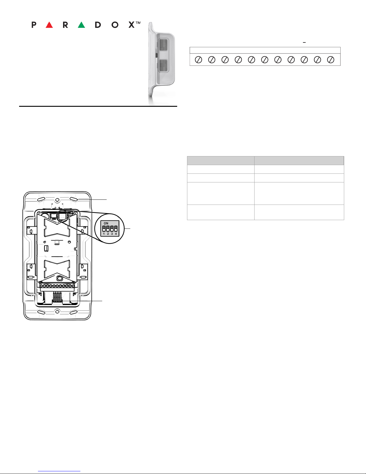
Screw Holes x6
Dip Switch
Wire Entry
TAMPER
N.C.
Z1*
EVO
N.C.L COM N.C.R RED BLK GRN YEL
+
Z2*
N.C.
AM
*In Single mode, both outputs activate from any side.
Installation Manual V1.0
Dual Side-View
Anti-Mask Outdoor
Detector
General Description
The NV780MX is a dual, independent, side-by-side view Passive
Infrared (PIR) motion detector with dual anti-mask in a single
housing, providing boundary protection. Covering approximately
24m / 78 ft. (12m / 39 ft. on each side) and configurable to report
either as a single unit with two sides reporting as a single zone
output or as a dual unit with each side reporting as a separate
zone input.
Installing the NV780MX
Wiring
• Digiplex mode is enabled if bus communication with the control
panel exists. In Digiplex mode, the detector’s relay output
remains active and can be used to activate other devices.
• Upon a loss of communication in Digiplex mode, the left LED
flashes rapidly until communication is restored.
• To return to Relay mode, disconnect both the power and the
Digiplex bus connection, and then power-up the module.
Dip Switch
Dip Switch Functionality
1 LED: ON / OFF
2 Buzzer: ON / OFF
3 Sensitivity
ON: (High)
OFF: (Low)
4 Single Mode: ON
Dual Mode: OFF
Figure 1 : Front View - Open Cover
Minimum Recommended Installation Distance: At least 40 cm /
15.7 in. from the protected area (door, window, etc.)
Anti-Mask Calibration
The anti-mask will only calibrate after the tamper is closed. The
NV780MX performs anti-mask calibration for up to 40 seconds,
indicated by flashing red / green LEDs until completed. On
completion, the LEDs shut off. If the buzzer is set to ON, three
beeps signal that calibration is complete.
IMPORTANT: During calibration, no objects should be within 2m /
6 ft. of the anti-mask field of view (on both sides of the detector).
Power-Up Sequence Indication
• LED: Both left and right LEDs blink red for five seconds.
• Buzzer Switch ON:
• Single Mode: One tone beeping for five seconds.
• Dual mode: Alternate tone beeping for five seconds.
• Anti-mask calibration can take up to 40 seconds, red / green
flashing if Buzzer is ON; three beeps indicates completion.
Alarm
• LED: Red LED indication on the relevant side(s) for three
seconds.
• Buzzer Switch ON:
• Single Mode: Same tone for either side detection.
• Dual mode: Each side has its own tone.
Anti-Mask Detection
• LED: Flashes orange rapidly (pre-alarm state) and then
flashes when in alarm.
• If Buzzer is ON: buzzer beeps for 3 seconds.
NOTE: The anti-mask relay is open during anti-mask detection.
Page 2
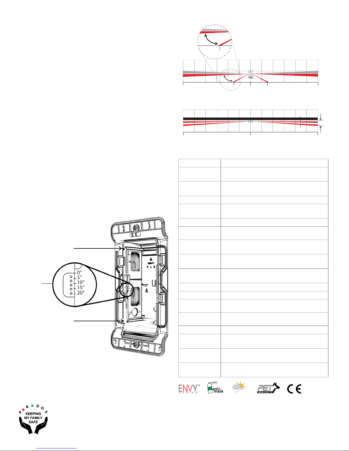
Adjusting the Beam Range
Slide Up
or Down
for Range
Adjustment
Pull Out for 0°
(Parallel Beam to Wall)
Push in for 3°
(Beam 3° from Wall)
0
0°
20°
12m
40 ft
3m
10 ft
3m
10 ft
12m
40 ft
0°
20°
3m
0°
3°
60 cm
012m
40 ft
12m
40 ft
Adjust the beam range by shifting the lower lens up and down:.
Hold the cover in the UP position and slide the plastic tab in the
lower lens up or down on the side you wish to adjust, until the
module is aligned in the desired position. Align the top of the tab
with the required angle of the beam (Figure 2):
0° = 12m
5°= 10.5m
10° = 7.5m
15° = 5.25m
20° = 3m
Once adjusted, lock into place by pushing the tab into the slot.
Adjusting the Horizontal Beam
Beams (on either side of the module) are projected parallel to the
wall (default). The beams can be adjusted to project 3
from the wall, distancing the beam 60 cm / 24 in. from the wall in
order to avoid detection of unwanted objects next to the module
(Figure 2).
To adjust the beams in relation to the wall, identify the side
needing adjustment, and slide the lens tray in or out of the detector
to the required position:
0° - Slide the lens tray until it is flush with the top edge of the lens
holder.
3° - Slide the lens tray until it is flush with the bottom edge of the
lens holder.
Figure 2 : Beam Adjustment
0
horizontally
Beam Range Adjustment
Horizontal Beam Adjustment
Technical Specifications
Sensor 4x dual low noise rectangular elements
Lens
Processing
Startup Time 25 seconds
Detection Speed
Power Input 9 Vdc to 15 Vdc
Current
Consumption
Coverage
PET Immunity
Anti- Mask Active IR detection for blocking 10 cm up to
Alarm Indicator 2x red LED for 3 seconds + buzzer
Alarm Output 2x Solid State, N.C, 150 mA.
Anti-Tamper
Switch
Operating
Temperature
Humidity 95% max.
Dimensions
RF Immunity
Standards
2nd gen., flat, 2x dual beam, 1.7” focal point,
narrow beam long-range Fresnel lens
Digital APSP / Digital temperature
compensation
0.2m / sec. – 4m / sec. (0.6 ft / sec. – 13.1 ft /
sec.)
Typical/Standby: 37mA, Max: 80mA
Bi-directional, independent, 2 x 3m to 12m
(10 ft. to 39 ft.) at 1.5m / 4.9 ft. height
Up to 40 kg (90 lb) - minimum 1.5m / 4.9 ft
installation height
30 cm and sprayed liquid
N.C. 28 Vdc, 0.15A
-35°C to +50°C / -31°F to +122°F
L 8.2 in. x W 4.3 in. x D 2.7 in.
(21 cm x 11 cm x 7 cm)
Complies with EN 50130-4: 10V / m 80 MHz
to 2.7 GHz
EN 50131-2-2, Security Grade 2,
EN 50130-5 Environmental Class IVA
Warra nty : For complete warranty information on this product please refer to the
Limited Warranty Statement found on the website: www.paradox.com/terms or
contact your local distributor. © 2016 Paradox Security Systems (Bahamas) Ltd. All
rights reserved. Specifications may change without prior notice.
Patents: One or more of the following US patents may apply: 7046142, 6215399,
6111256, 6104319, 5920259, 5886632, 5721542, 5287111, and RE39406 and other
pending patents may apply. Canadian and international patents may also apply.
NV780MX-EI00 01/2016
 Loading...