

ParaBody Serious Steel 893103 Assembly Manual
Serious Ste~
-893103 PRO SYSTEM
II Illl
Illl
ASSEMBLY INSTRUCTIONS
Part # 6753901
1
l~evision:10F27/97
I I ,M2ORTANT NOTESJ
WELCOME TO THE WORLD OF
Please note:
* Thank you for purchasing the Parabody 893103 PRO SYSTEM. Please :read these instructions
thoroughly and keep them for future reference. This product must be assembled on a flat, leve
surface to assure its proper function.
* We recommend cleaning your product (,pads and frame) on a regular ba~sis, using warm soapy
water. T~uch-up paint can be purchased from your Parabody customer service representative
at (800) 328-9714.
There is a risk assumed by individuals who use this type of equipment. To minimize risk, please
follow these rules:
1.
Inspect equipment daily. Tighten all loose connections and replace worn parts immediately.
Failure to do so may result in serous injury.
2. Do not allow minors or children to play on or around this equipment..
3.
Exercise with care to avoid injury.
4. If unsure of proper use of equipment, call your local Parabody distributor or call the
Parabody customer service department at (800) 328-9714.
5. Consult a physician before beginning any exercise program.
[ Tools Required forAssembly
*
3/4" wrench
* 9/16" wrench
* l~tchet with 3/4" and 9/16" sockets
* Adjustable wrench
* Tape measure
[ Bolt Length Ruler
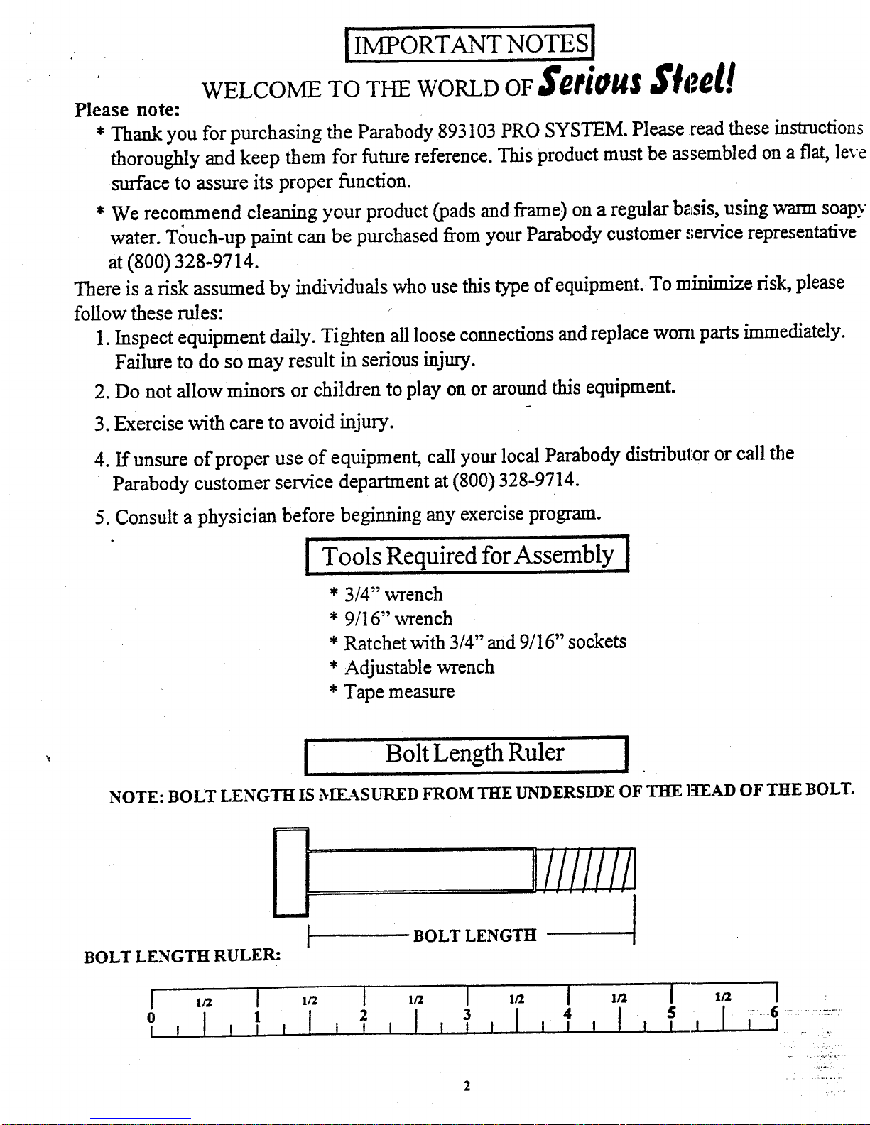
NOTE: BOLT LENGTH IS MY_ASURED FROM "HIE IYNI)ERS[DE OF TI~ lq’l~Al) OF THE BOLT.
E
IIIIIII
I
BOLT LENGTH [
BOLT LENGTH RULER:
4 I ! l_l
2
3
I I I !
I
2
1
2
4
6
7
9
10
11
12
13
15
16
17
18
19
20
21
22
23
24
25
26
27
28
PART #
656603
6566702
6546302
6566903
6567002
6581102
6569802
6567302
6567502
6567803
6516502
6568102
6568303
6568603
6568703
6370403
6342402
6274402
6597402
6194601
6176201
6189501
3116201
6576201
6492201
3102918
3102910
3102922
TOP BOOM
CARRIAGE
BENTTUBE
UPRIGHT
LAT BAR
BOOM SUPPORT LEFr
BOOM SUPPORT RIGI--I’F
SAFETY RAIL
sWIVEL KNEE SUPPORT
PULLEY BRACKET
LOW ROW ATTACI-IMENT
BEARING HOUSING
PEC ARM RIGHT
PEC ARM LEFT
CENTER PULLEY BRACKET
1-3/4 X 5-1/4" PLATE
LOW ROW B.~R
BACK PAD
4 X 7" ROLLER PAD
4 X 12" ROLLER PAD
’ U’~RIGHT LABELS
3-1/2" PULLEY
PEC CABLE
LAT & LOW ROW CABLE
1/2 X 3-1/4"" BOLT
1/2 X 3" BOLT
3/8 X 2-3/4"" BOLT
PARTS LIST
QTY
~ PART #
DESCRIPTION
1
29 3102933
3/ Z2"’ BOLT
1 30
3102502
I/2" WASHER
1 31
3102501
3t WASHER
1
32 3102602
1/2"I. XIK WASHER
2
33
3102601
3/$" I KIK WASHER
1
34
3102801
112
1
35 3102804
1/2" L(~W HT LOCK NUT
1 36
3102802
3/8" LOCK NLrr
2
37
3103801 -~ 4/d
~ LI]qK
1
38
3108102
QUICK L~NK
1
3 9
6075906
CHAIN
1
40 6412001
3/8" SPI~,IG PIN ASSEMBLY
1
41
3104901
3/4" FL ~N GE BEARING
1 42
6480301
3/8"F[ ~GE SPACER
1
43 6145801
Tl-i ~[BSCP, EW
1
44
-6692601
3 X 2" END CAP
2 45
3119301
2-1/2" ROLFND END CAP
1
46
6236701
1-3/4’ SQ. END CAP
I
47
6405201
2:’ ~Q. END CAP
2
48 6467001
C :~IH~, CAP
2
49
6484101
STAR ,OCK COLLAR
2
50
3103102
1 X :g" GRIP
11 51
3116001
1-1/4" SQ. RU’BBER BUM~ER
1
52 3120702
3/. CAP NUT
2
53
6140701
I’ SQ. GLIDE
7
54 6416601
1-1/2 X 3/4"" GLIDE
6
~3
6177001
NOII,~-S KID STRIP
12
56
6533501
CABLE RETA.h-N’~’G
7
3
6
3
’2
9
1
17
3
2
1
3
4
8
2
1
2 ’
I
8
2 ’
2
4
1
2
10
2
4
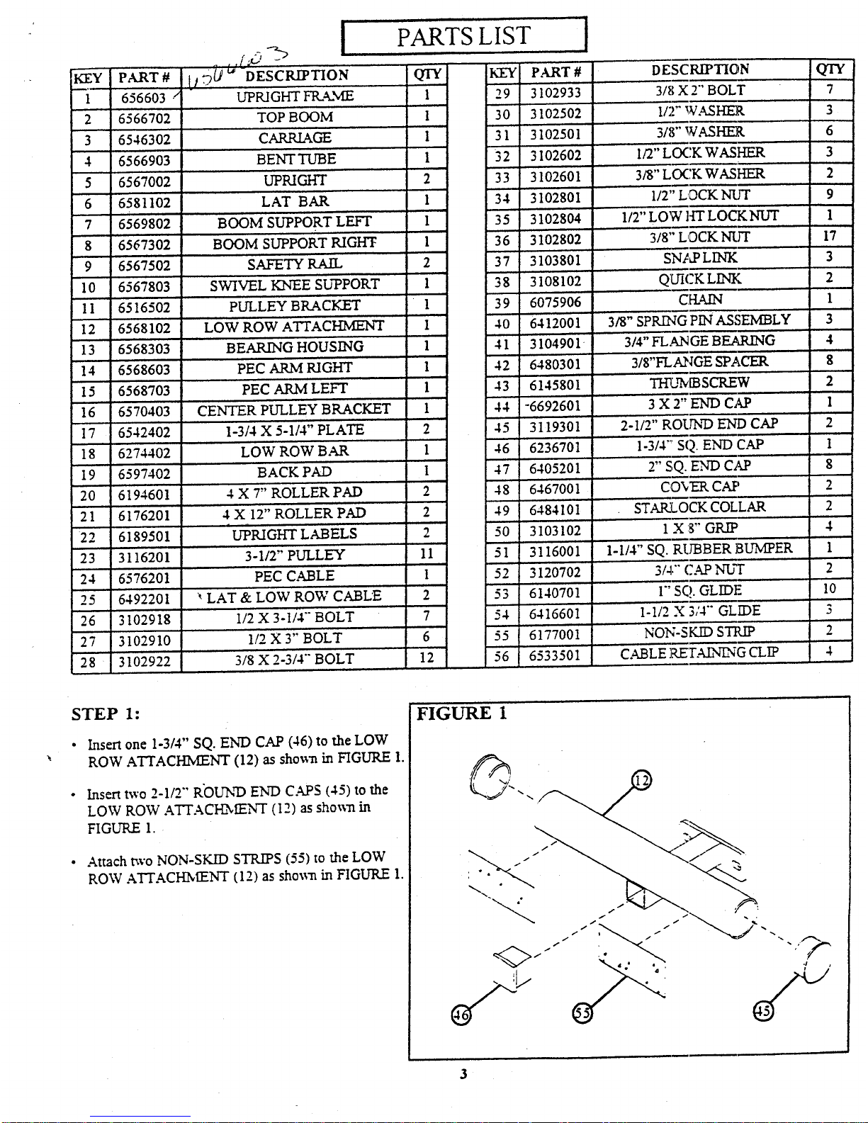
STEP 1:
¯
Insert one 1-3/4’" SQ. END CAP (46) to the LOW
ROW ATTACHMENT (12) as shoma in FIGURE
Insert two 2-1/2"" R’OUND END CAPS (45) to the
LOW ROW ATTACI-hMENT (12) as sho~m
FIGURE 1.
¯
Attach two NON-SKID STRIPS (55) to the LOW
ROW A’F’I’ACH2~IENT (12) as shown in FIGURE
FIGURE 1
, FIGURE 2
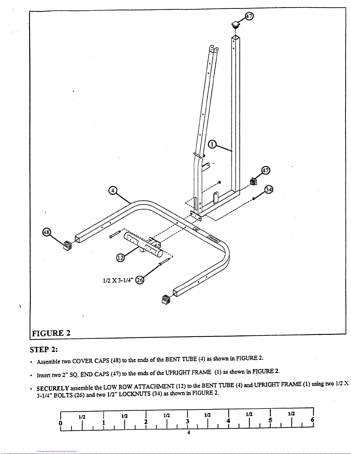
STEP 2:
¯ Assemble two COVER CAPS (48) to the ends of the BENT TUBE (4) as shown in HGURE
¯ Insert two 2" SQ. END CAPS (47) to the ends of the LrpRIGHT FRAME (1) as shown in FIGLTRE
¯
SECURELY assemble the LOW ROW ATTACHmeNT (12) to the BENT TLTBE (4) and UPRIGHT FRAME (1) using two
3-1/4" ~OLTS (26) and two 1/2" LOCKNt~S (34) as sho~’a in HGLrRE
5
[ I
1
I I I I
0 ! I I
I
I 1
4
3~8 X 2-3/4"
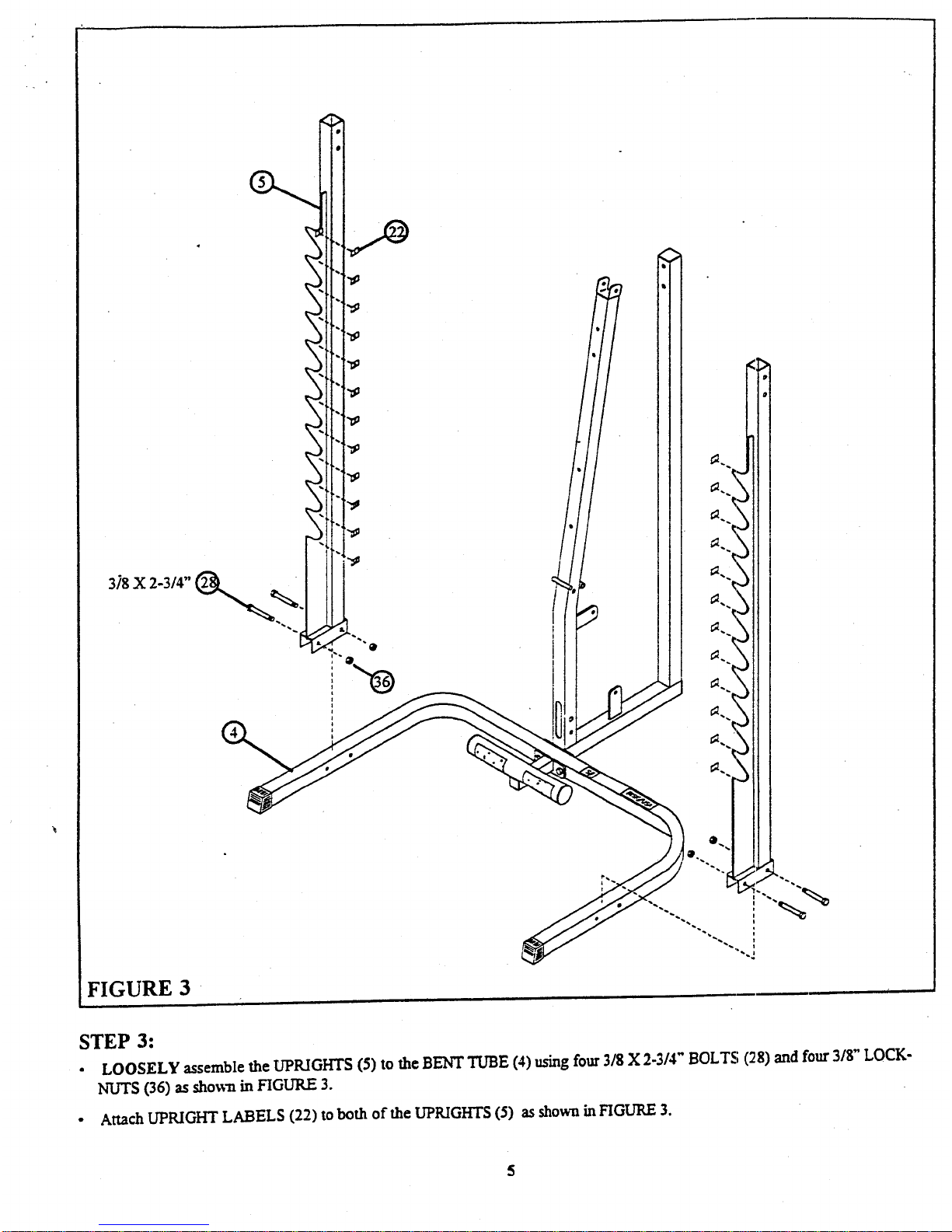
FIGURE 3
STEP 3:
¯ LOOSELY assemble the UPRIGHTS (5) to the BENT TUBE (4) using four 3/8 X 2-3/4" BOLTS (28) and four 3/$"
N’U~S (36) as shown in FIGURE 3.
¯
Attach UPRIGHT LABELS (22) to both of the UPRIGHTS (5) as shown in HGURE
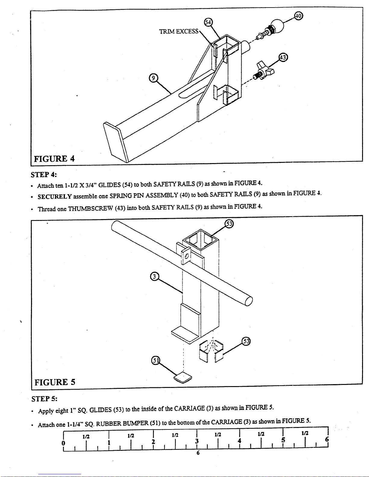
FIGURE 4
STEP 4:
¯ Attach ten 1-1/2 X 3/4" GLIDES (54) to both SAFETY RAILS (9) as shown in FIGURE
¯ SECURELY assemble one SPRING PIN ASSEMBLY (40) to both SAFETY RAILS (9) as shown in FIGURE
¯ Thread one TH’UMBSC1LEW (43) into both SAFETY RAILS (9) as shown in FIGURE
FIGURE 5
STEP 5:
¯ Apply eight 1" SQ. GLIDES (53) to the irtside of the CARRIAGE (3) as showrt in FIGURE 5.
¯ Attach one I-1/4", SQ. RUBBER BUMPER (51) to the bottom ofthe CAR.1UAGE (3) as shown in FIGtJR.E
[ 1/2 I 1/2
I
1/2 I I~2 I 1/2 [-- 1/2
2
[ I I I
 Loading...