

ParaBody Serious Steel 877102 Assembly Manual
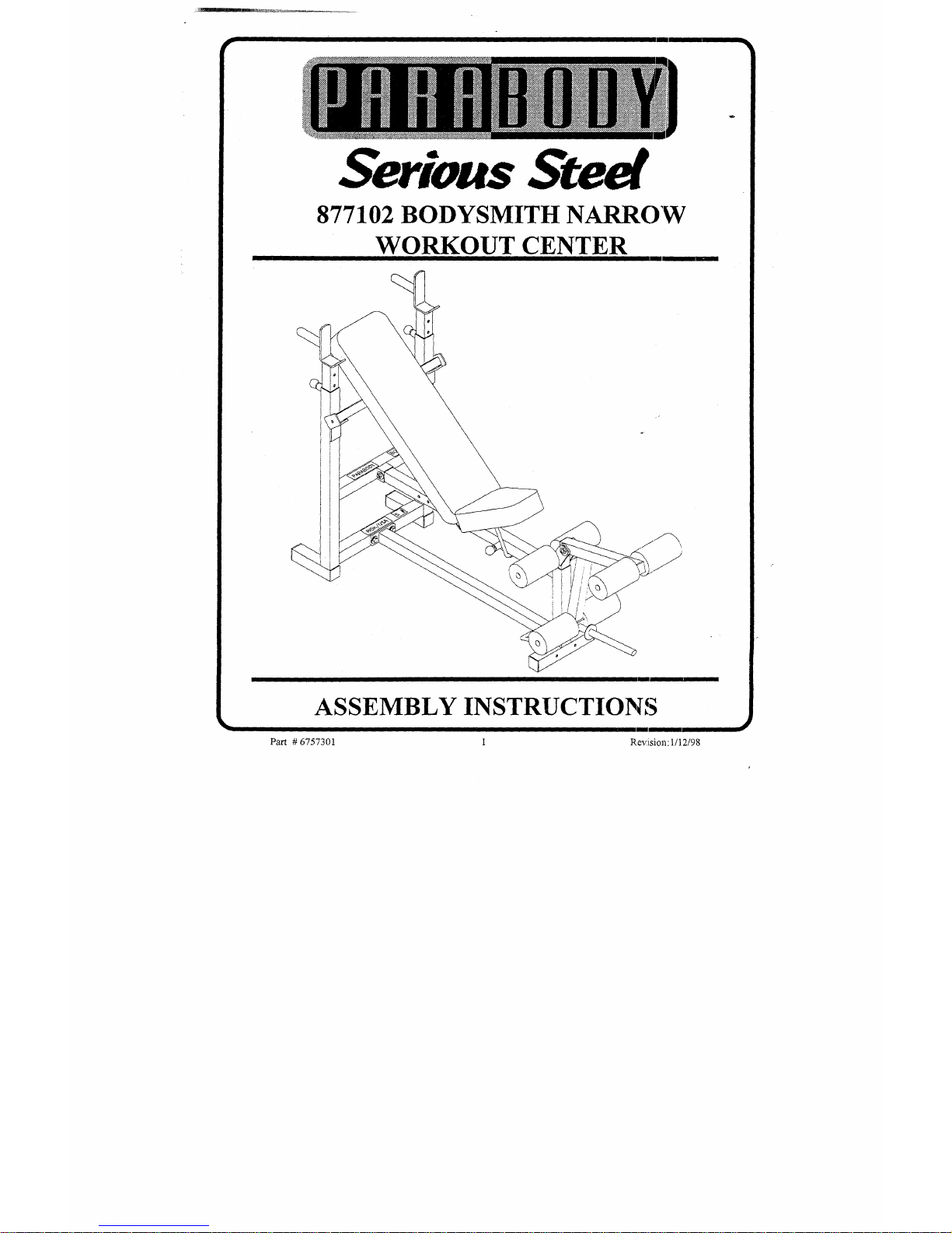
Serious Steel
877102 BODYSMITH NARROW
WORKOUT CENTER
I
ASSEMBLY INSTRUCTIONS
Part # 6757301
t~.evlision: 1/12/98
[ IMPORTANT NOTES’]
WELCOME TO THE WORLD OF
Please note:
* Thank you for purchasing the Parabody 877102 BODYS1VHTH NARROW WORKOUT
CENTER. Please read these instructions thoroughly and keep them for future reference.This
product must be assembled on a flat, level surface to assure its proper function.
*
We recommend cleaning your product (pads and flame) on a regular basis, using warm soapy
water. Touch-up paint can be purchased from your Parabody customer serv~ice representative
at (800) 328-9714.
There is a risk assumed by individuals who use this type of equipment. To miniraize risk, please
follow these rules:
1. Inspect equipmem daily. Tighten all loose connections and replace worn pa:~ts immediately.
Failure to do so may result in serious injury.
2. Do not allow minors or children to play on or around this equipment.
3. Exercise with care to avoid injury.
4.
If unsure of proper use of equipment, call your local Parabody distributor or call the
Parabody customer service department at (800) 328-9714.
5. Consult a physician before beginning any exercise program.
[ Tools Required for Assembly
* 3/4" wrench
* 9/16" wrench
*
Ratchet with 3/4" and 9/16" sockets
* Adjustable wrench
* Tape measure
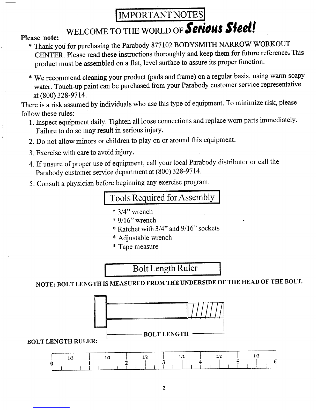
Bolt Length Ruler
NOTE: BOLT LENGTH IS MEASURED FROM THE UNDERSIDE OF TH-E HEAD OF THE BOLT.
BOLT LENGTH RULER:
~llll!iiil
BOLT LENGTH
1/2 ]
1/2
I
1/2 [ 1/2 [ 1/2
I 1/2
6
I ..........
p,,ARTS LIST
KEY
1
2
3
4
PART #
6407103
6407503
6100402
DESCRIPTION
UPRIGHT FRAME
BENCH FRAME
HEIGHT ADJUSTMENT BAR
QTY
1
1
1
1
6406602
5 6407802
6 6407302
WOLFF SLEEVE
BASE LEG
L
SADDLE
2
7
11
12
13
14
15
16
17
18
19
6024702
6407202 LEG EXTENSION NECK
1
1
6406401
6406501
6125101
61’94601
6654502
6654102
3102909
3102922
3102904
3102910
3102501
20 3102601
21 3102804
22
23
24
25
26
27
28
29
30
31
32
33
3102502
6236701
3102804
6412001
6020601
LEG EXTENSION
HINGE TAB
’"U’PIN
ROLLER PAD SHAFT
" ’ ROLLER PAD
SEAT PAD
BAcK PAD
3/8 X 1" BOLT
3/8 X 2-3/4" BoLT
3/8 X 3" BOLT
1/2 X 3" BOLT
3/8" WASHER
3/8" LOCK WASHER
3/8" LOCK NUT
1/2" WASHER
1-3/4" SQ. END cAP
1/2" LOW HEIGHT LOCK NUT
3/8" SPRING PIN ASSEMBLY
1/2" FLANGE BEARING
3105401 3/4" STARLOCK COLLAR
3109602 PAL NUT
6145801 THUMBSCREW
3103101
6416601
3104301
6405201
1-1/4 X 5" GRIP
PARAGLIDE STRIP (8 ct.)
3/4" sO. RUBBER,BUMPER
2" SO. END CAP
4
2
2
1
10
4
3
2
4
1
3
2
6
2
4
2
3
6
4
2
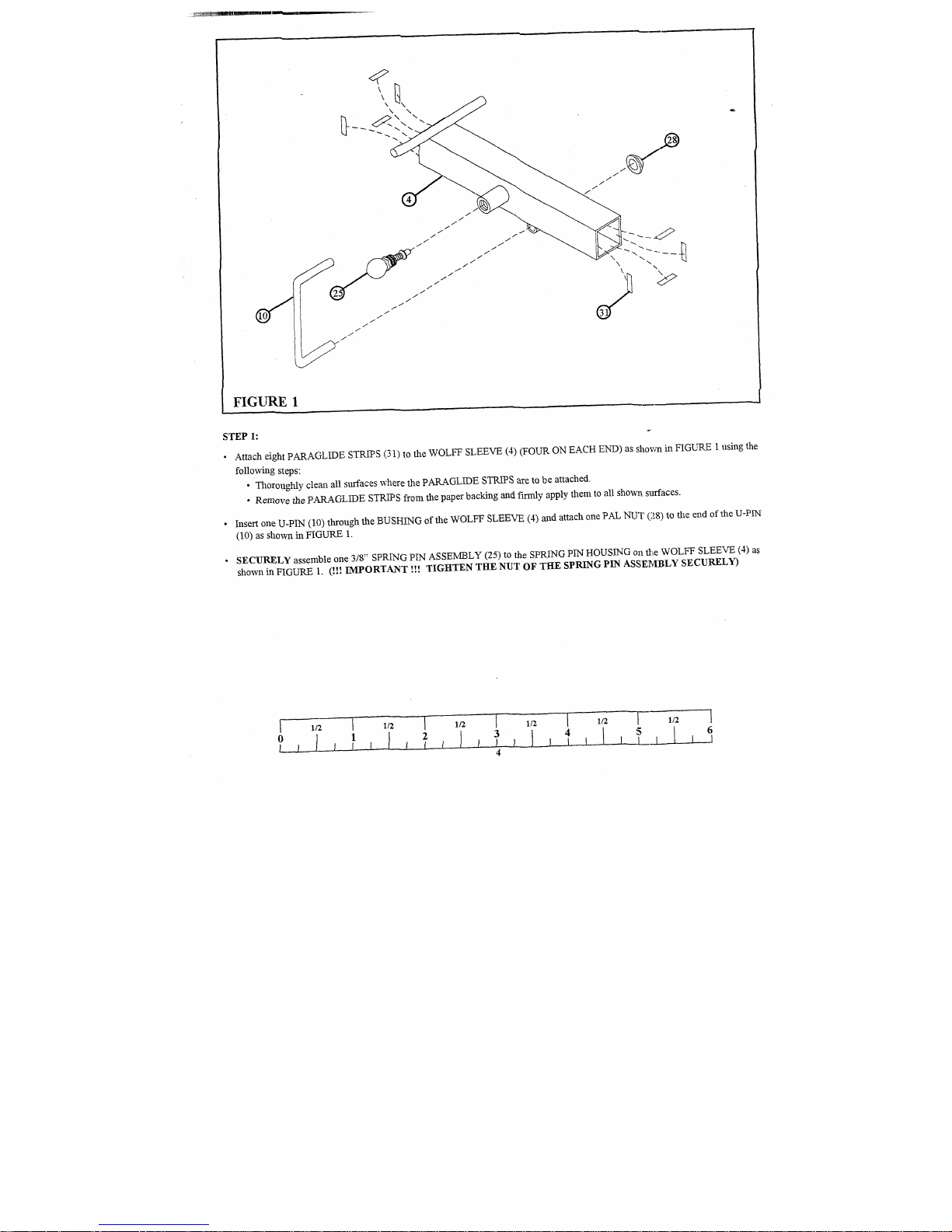
FIGURE 1
STEP 1:
¯
Attach eight PARAGLIDE STRIPS (31) to the WOLFF SLEEVE (4) (FOUR ON EACH END) as shown in FIGURE 1 using
following steps:
¯ Thoroughly clean all surfaces where the PARAGLIDE STRIPS are to be attached.
¯ Remove the PARAGLIDE STRIPS from the paper backing and fLrmly apply them to all shown surfaces.
¯
Insert one U-PIN (10) through the BUSHING of the WOLFF SLEEVE (4) and attach one PAL NUT (28) to the end of the
(10) as shown in FIGURE
¯
SECURELY assemble one 3/8" SPRING PIN ASSEMBLY (25) to the SPRING PIN HOUSING on file WOLFF SLEEVE (4)
shown in FIGURE 1. (!!! IMPORTANT !!! TIGHTEN THE NUT OF THE SPRING PIN ASSE~cIBLY SECURELY)
1/2 I 1/2 I 1/2 I 1/2 I 1/2 I 1/2
6
 Loading...