

ParaBody Serious Steel 445103 Assembly Manual
Serious Ste~
445103 425 SECOND STACK OPTION
ASSEMBLY INSTRUCTIONS
Part # 6747401
I
l~evision: 09/25/97
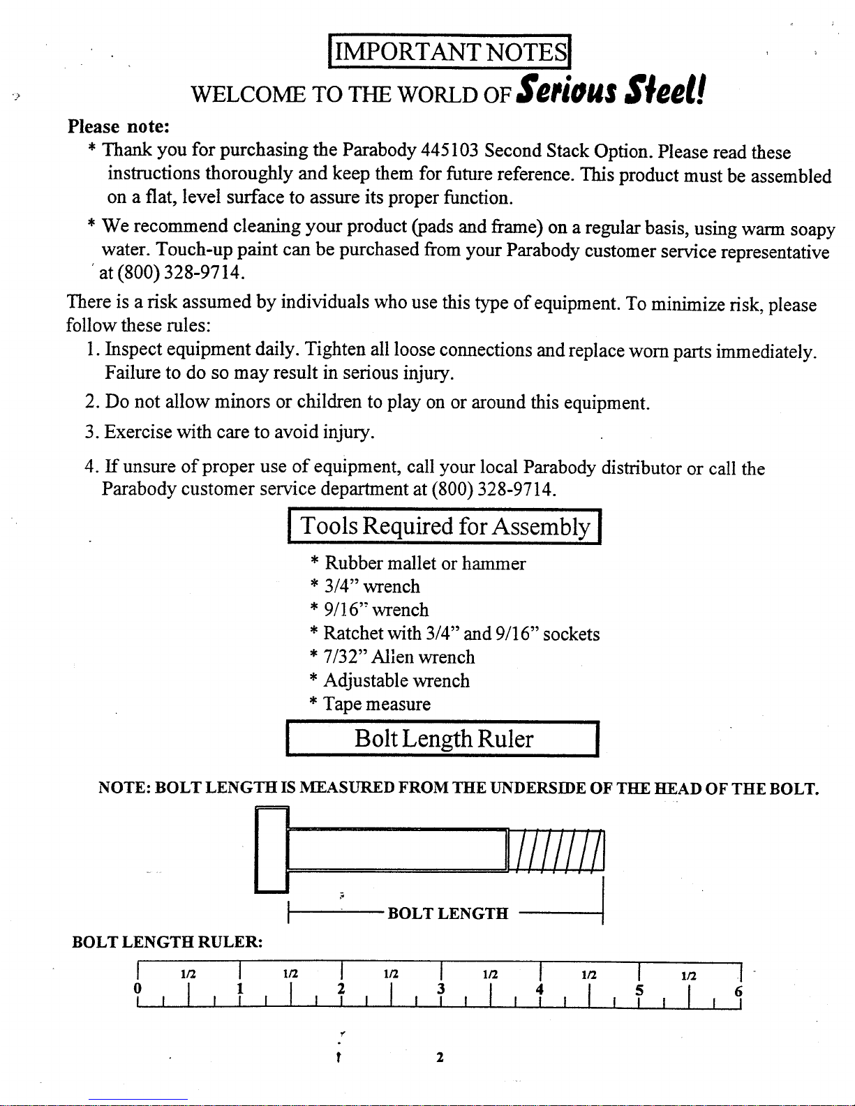
NOTE: BOLT LENGTH IS MEASURED FROM THE UNDERSIDE OF THI~ HEAD OF THE BOLT.
Iliiiii!!1
BOLT LENGTH
BOLT LENGTH RULER:
2
4 5
6
[IMPORTANT NOTES[
WELCOME TO THE WORLD OF Seeiou~
Please note:
* Thank you for purchasing the Parabody 445103 Second Stack Option. Please read these
instructions thoroughly and keep them for future reference. This product must be assembled
on a flat, level surface to assure its proper function.
* We recommend cleaning your product (pads and flame) on a regular basis, using warm soapy
water. Touch-up paint can be purchased from your Parabody customer service representative
’at (800) 328-9714.
There is a risk assumed by individuals who use this type of equipment. To minimize risk, please
follow these rules:
1.
Inspect equipment daily. Tighten all loose connections and replace worn parts immediately.
Failure to do so may result in serious injury.
2. Do not allow minors or children to play on or around this equipment.
3. Exercise with care to avoid injury.
4. If unsure of proper use of equipment, call your local Parabody distributor or call the
Parabody customer service department at (800) 328-9714.
~ Tools Required for Assembly
* Rubber mallet or hammer
* 3/4" wrench
* 9/16" wrench
* Ratchet with 3/4" and 9/16" sockets
* 7/32" Allen wrench
* Adjustable wrench
*
Tape measure
[ Bolt Length Ruler [
I
2
3
4
5
6
8
9
PART# DESCRrPT~Or~
6523401 GUIDE ROD
6266001 WEIGHT STACK SHAFT ’"
6375902 1-i/4 SQ. X 4-7/8 ~E
671~601 ~ PLA~BLA~
6747501 P~SS-S~ACK ~LE
3’116101 4~’i/~" P~LEY
*h~4o~ SVA~e~
3108002 ~IG~ STA~ COSmON
3117401 C~ PLUG
PARTS LIST
2 10
2
12
1 16
2 17
4 18
PART#
DESCRIP ~N
3102501 3/8" WASHF, R
3102802 3/8" LOCKNUT
6480301 3/8" FLANGE SF’ACER
3102922 3/8X2-3~" DLT
3102901 3/8X 1-1~" DLT
3102503
3~"WASHER
6214501
WEIGHTF~ATE
6382301 WEIGHTPLATEBUSHING 10CT.
6189501
WEIGHTSTAC BF_.L
1
2
15
3
i
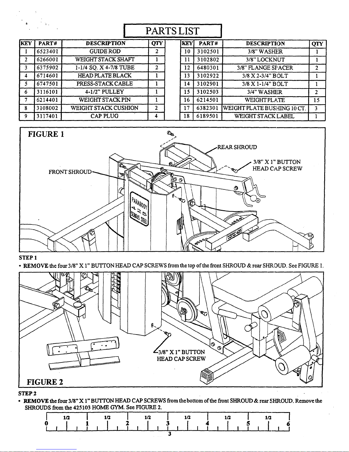
FIGURE 1
~
REAR SHROUD
FRONT S
CAP SCREW
STEP 1
¯ RIgMOVE the four 3/8" X 1" BUTTON HEAD CAP SCREWS from the top of the front SHROUD & rear SHROUD. See FIGURE 1.
HEAD CAP SCRE~ ~ ~~
FIGURE 2
STEP 2
¯ REMOVE the four 3/8" X 1" BU’I~ON HEAD CAP SCREWS from thebottom of the front SHROUD & re;~r S;HROUD. Remove the
SHROUDS from the 425103 HOME GYM. See FIGURE 2.
0
I
2
I I
4
!
5
6
I I I I, ! I I, I I
1 ] , I I
I
ill
, I I II 1
PLATE
CABLE
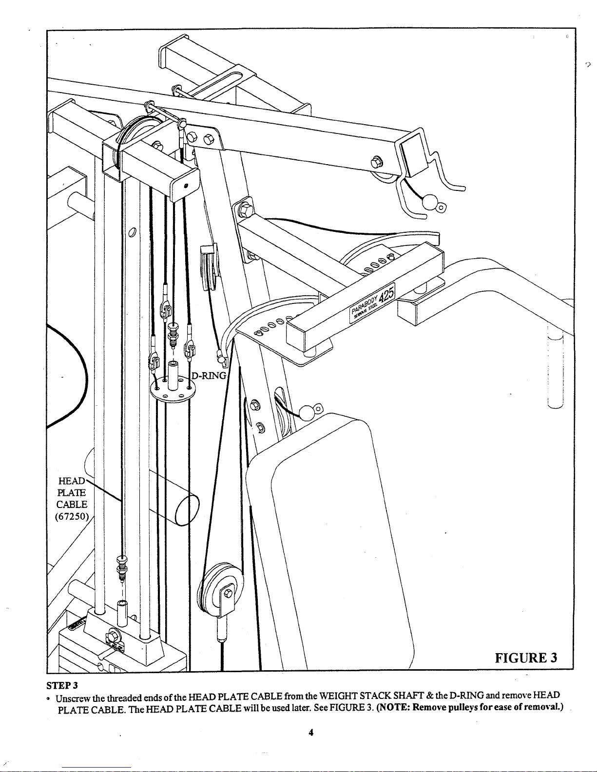
FIGURE 3
STEP 3
¯ Unscrew the threaded ends of the HEAD PLATE CABLE from the WEIGHT STACK SHAFT & the D-RING and remove HEAD
PLATE CABLE. The HEAD PLATE CABLE will be used later. See FIGURE 3. (NOTE: Remove pulleys for ease of removal.)
PRESS TENSION CORD
i
t COTTERPIN~
KEYI-IOLE CLEVIS,,~~
PRESS C
(67249)
LAT CABLE
(667248)
LEG CURL/EXTENSION CABLE
(67247)
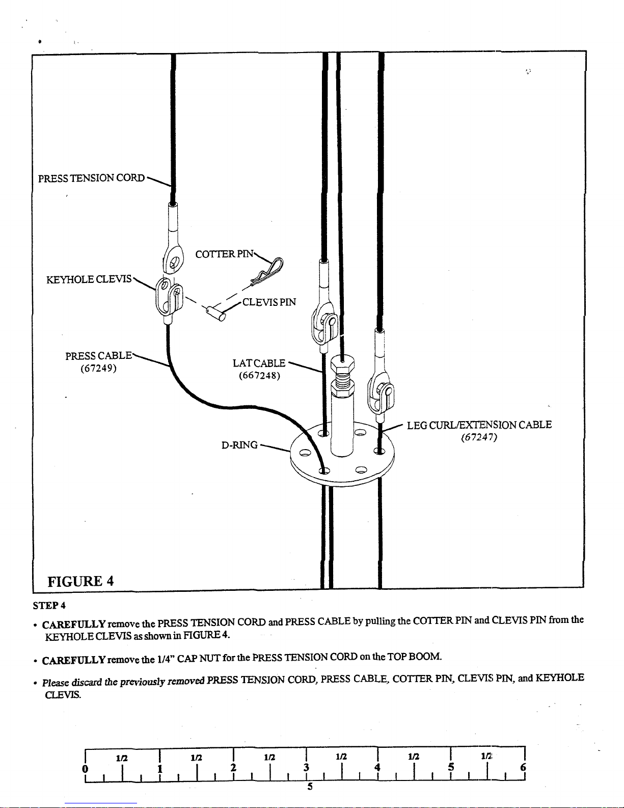
FIGURE 4
STEP 4
¯ CAREFULLY remove the PRESS TENSION CORD and PRESS CABLE by pulling the COTTER PIN and CLEVIS PIN from the
KEYHOLE CLEVIS as shown in FIGURE 4.
¯ CAREFULLY remove the 1/4" CAP NUT for the PRESS TENSION CORD on the TOP BOOM.
¯ P/ease d/scm’d the previously removed PRESS TENSION CORD, PRESS CABLE, COTTER PIN, CLEVIS PIN, and KEYHOLE
CLEVIS.
[ lt2
I
1~2 [
lt~ [
1/2
[
1~
[
1/~: [
2 3
! !
4
[ l l l
6
0l l I i
11
l l l i
I I
l i i , l
 Loading...