

ParaBody Serious Steel 435103 Assembly Manual
I
Serious Steel
435103 LEG PRESS ADAPTER. KIT
I
ASSEMBLY INSTRUCTIONS
Part # 6747801 1
Revision: 09/25/97
]IMPORTANT NOTES]
WELCOME TO THE WORLD OF $~eiOU$ $~l~i!t
Please note:
* Thank you for purchasing the 435103 Leg Press Adapter Kit. Please read these
instructions thoroughly and keep them for future reference. This product must be assembled
on a flat, level surface to assure its proper function.
* We recommend cleaning your product (pads and frame) on a regular basis, using warm soapy
water. Touch-up paint can be purchased from your Parabody customer service representative
at (800) 328-9714.
There is a risk assumed by individuals who use this type of equipment. To minimize risk, please
follow these roles:
1.
Inspect equipment daily. Tighten all loose connections and replace worn parts immediately.
Failure to do so may result in serious injury.
2. Do not allow minors or children to play on or around this equipment.
3. Exercise with care to avoid injury.
4. If unsure of proper use of equipment, call your local Parabody distributor or call the
Parabody customer service department at (800) 328-9714.
I Tools Required for Assembly i
* Rubber mallet or hammer
* 3/4" wrench
*
9/16" wrench
* Ratchet with 3/4" and 9/16" sockets
* 7/32" Allen wrench
* Adjustable wrench
* Tape measure
Bolt Length Ruler I "
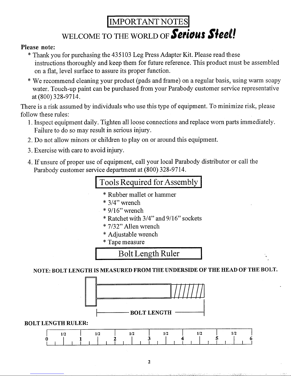
NOTE: BOLT LENGTH IS MEASURED FROM THE UNDERSIDE OF Tl=l-E H~EAD OF THE BOLT.
BOLT LENGTH RULER:
[ 112 [
0
I
1
BOLT LENGTH
1/2
~
1/2
I
1/2 I 1/2 I 1/2
6
4
I ’ ’
2
KEY
1
2
3
4
5
6
7
8
PART# DESCRIPTION
6747603 FRONT LEG
3116202 3-1/2" PULLEY
3108102 QUICK DISCONNECT LINK
6427101 KEYHOLE CLEVIS
3117305
CLEVIS PIN
3112901
COTTER PIN
6732901 TENSION CORD
6747901
LEGPRESS CABLE
PARTS LIST
QTY KEY PART#
1
9 6535301
2 10 3102501
1 11 3102802
1
12 3102502
1 13 3102801
1
14 3102933
1 15 3102910
1
DESCRIP’.rlON QTY
1/4" CAP NUT 1
3/8" W, HER
4
3/8" LOCKNUT
2 .
1/2" W, HER 4
1/2" LOCKNUT
4
3/8X2 BOLT
2
1/2X3 BOLT
4
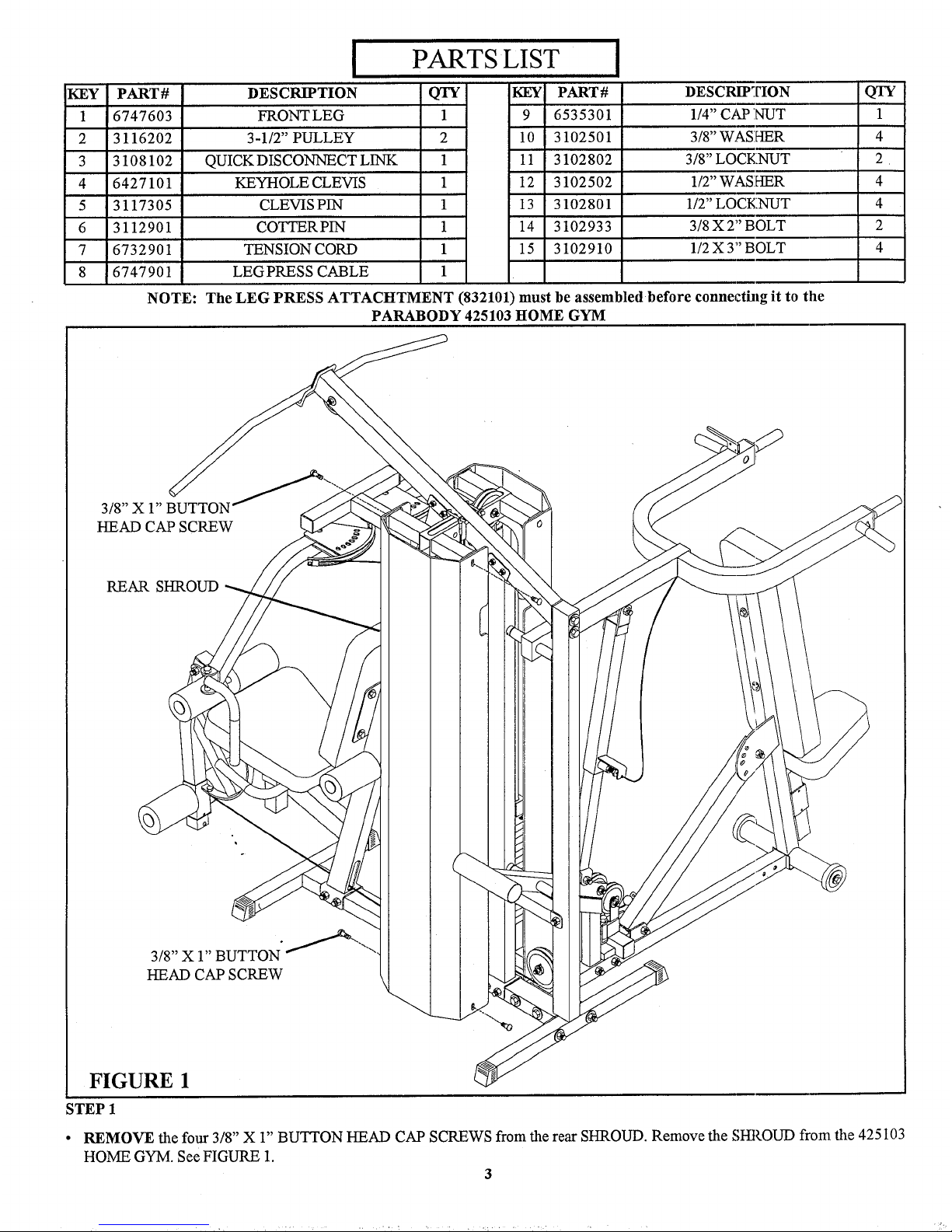
NOTE: The LEG PRESS ATTAClqTMENT (832101) must be assembled before connecthlg it to the
PARABODY 425103 t~OME GYM
3/8" X 1"
HEAD CAP SCREW
3/8" X 1" BUTTON
HEAD CAP SCREW
FIGURE 1
STEP 1
¯
REMOVE the four 3/8" X 1" BUTTON HEAD CAP SCREWS from the rear SHROUD. Remove the SHROUD from the 425103
HOME GYM. See FIGURE 1.
3
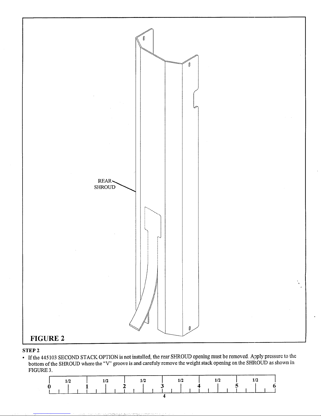
FIGURE 2
STEP 2
¯
If the 445103 SECOND STACK OPTION is not installed, the rear SHROUD opening must be removed. AI?ply pressure to the
bottom of the SHROUD where the "V" groove is and carefuly remove the weight stack opening on the SHROUD as shown in
FIGURE 3.
1/2 [ 1/2 [ 1/2 I 1/2 [ 1/2
6
 Loading...