

ParaBody Serious Steel 426103 User Manual
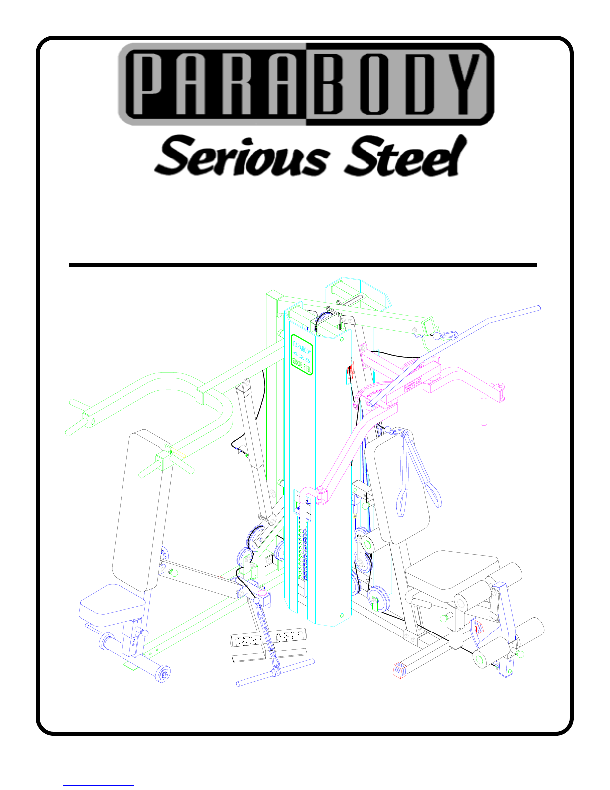
426103 ELASTIC CORD
CONVERSION KIT
1Part # 6860801 Revision: 10/12/99
P AR TS LIST
KEY
PART #
3102903
1
6122702
2
3201501
3
6271801
4
3118701
5
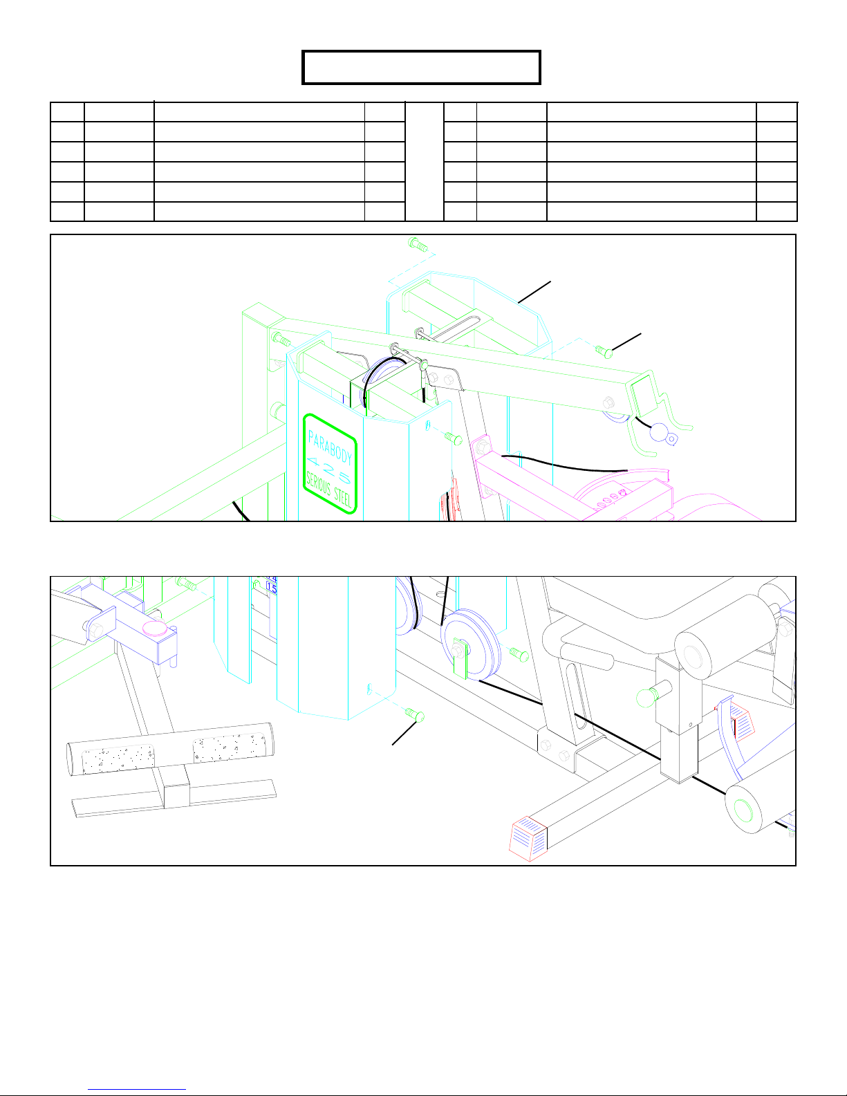
FIGURE 1
DESCRIPTION
3/8 X 2-1/2” BOL T
3/8 X 1/2” SP ACER
SWIVEL SNAP
22” ELASTIC CORD
2” PULLEY
QTY
2
4
4
4
4
KEY
6
7
8
9
10
PART #
3102501
3102802
3102701
6535001
3102909
DESCRIPTION
3/8” W ASHER
3/8” LOCK NUT
3/8” HEX NUT
3/8” THREADED SHAFT
3/8” X 1” BOL T
SHROUD
3/8” X 1” BUTTON
HEAD CAP SCREW
QTY
4
7
8
3
1
STEP 1
• Remove the top of the front SHROUD & rear SHROUD by removing the four 3/8” X 1” BUTTON HEAD CAP SCREWS. See FIGURE 1.
3/8” X 1” BUTTON
HEAD CAP SCREW
FIGURE 2
STEP 2
• Remove the bottom of the front SHROUD & rear SHROUD by removing the four 3/8” X 1” BUTTON HEAD CAP SCREWS. See
FIGURE 2
!IMPORTANT!
• IF THE 832 LEG PRESS OPTION IS INST ALLED PROCEED TO PAGE 14.
• IF THE 445 WEIGHT STACK OPTION IS INSTALLED PROCEED T O PAGE 27.
• IF THE 832 LEG PRESS OPTION & 445 WEIGHT ST ACK OPTION ARE INSTALLED PROCEED T O
P AGE 35.
• IF NO OPTIONS ARE INSTALLED CONTINUE T O PAGE 3.
2
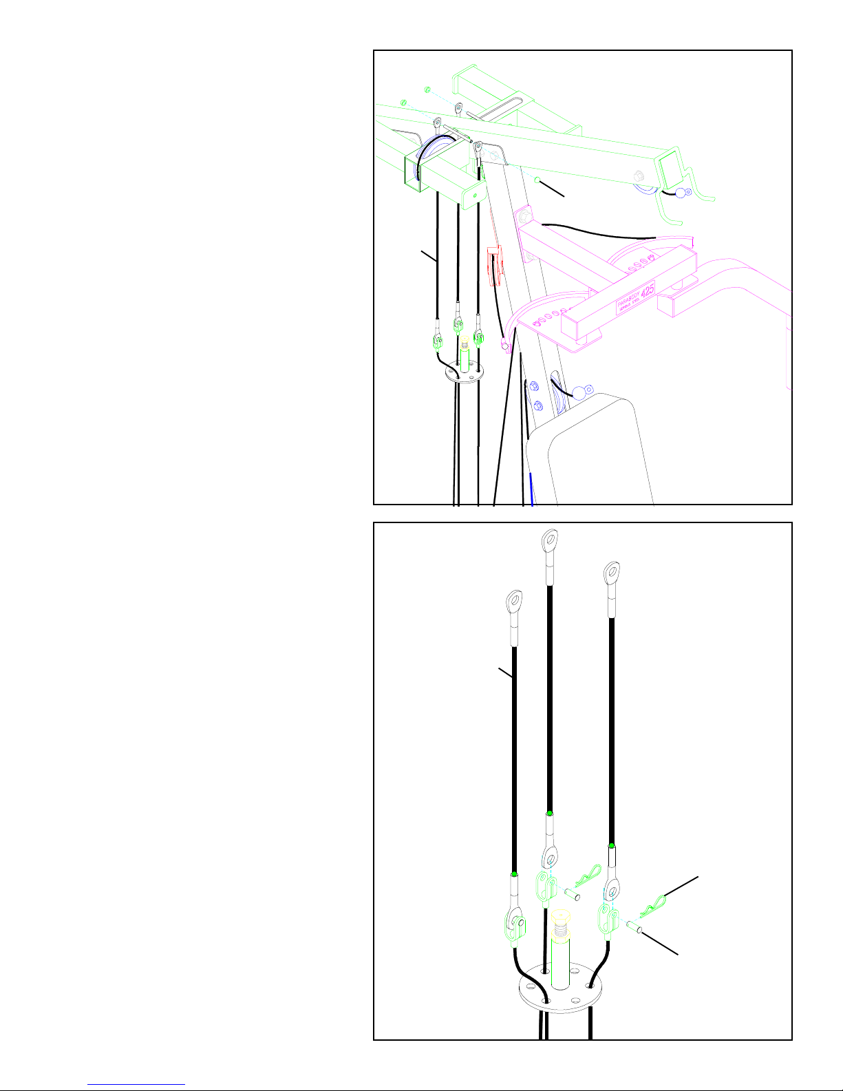
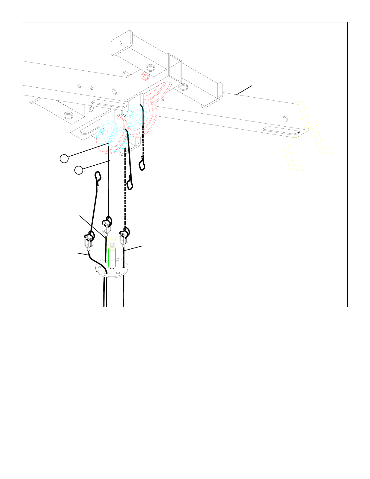
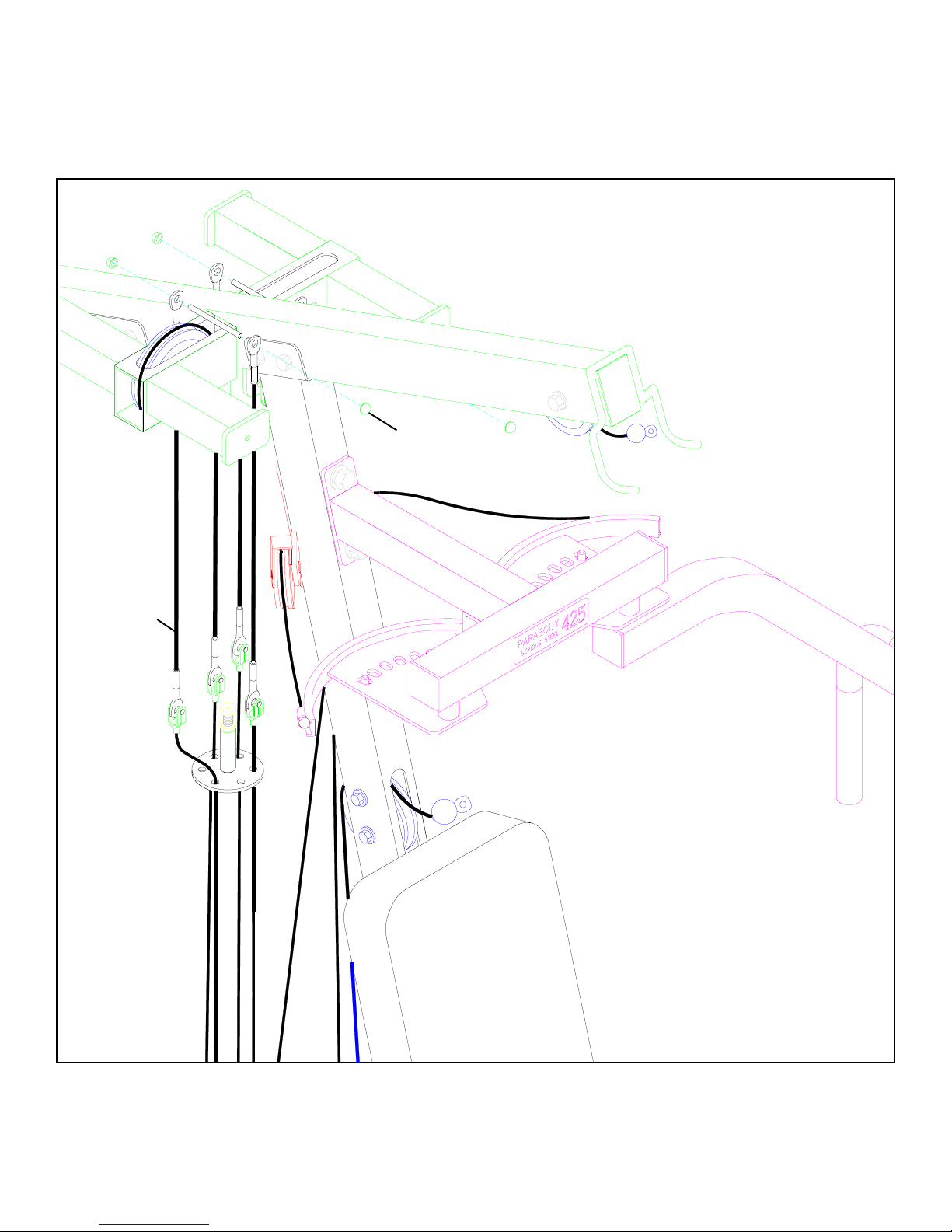
STEP 3
• Remove the three 1/4” CAP NUTS and each TENSION
CORD from the TOP BOOM as shown in FIGURE 3.
FIGURE 3
CAP NUT
CORD
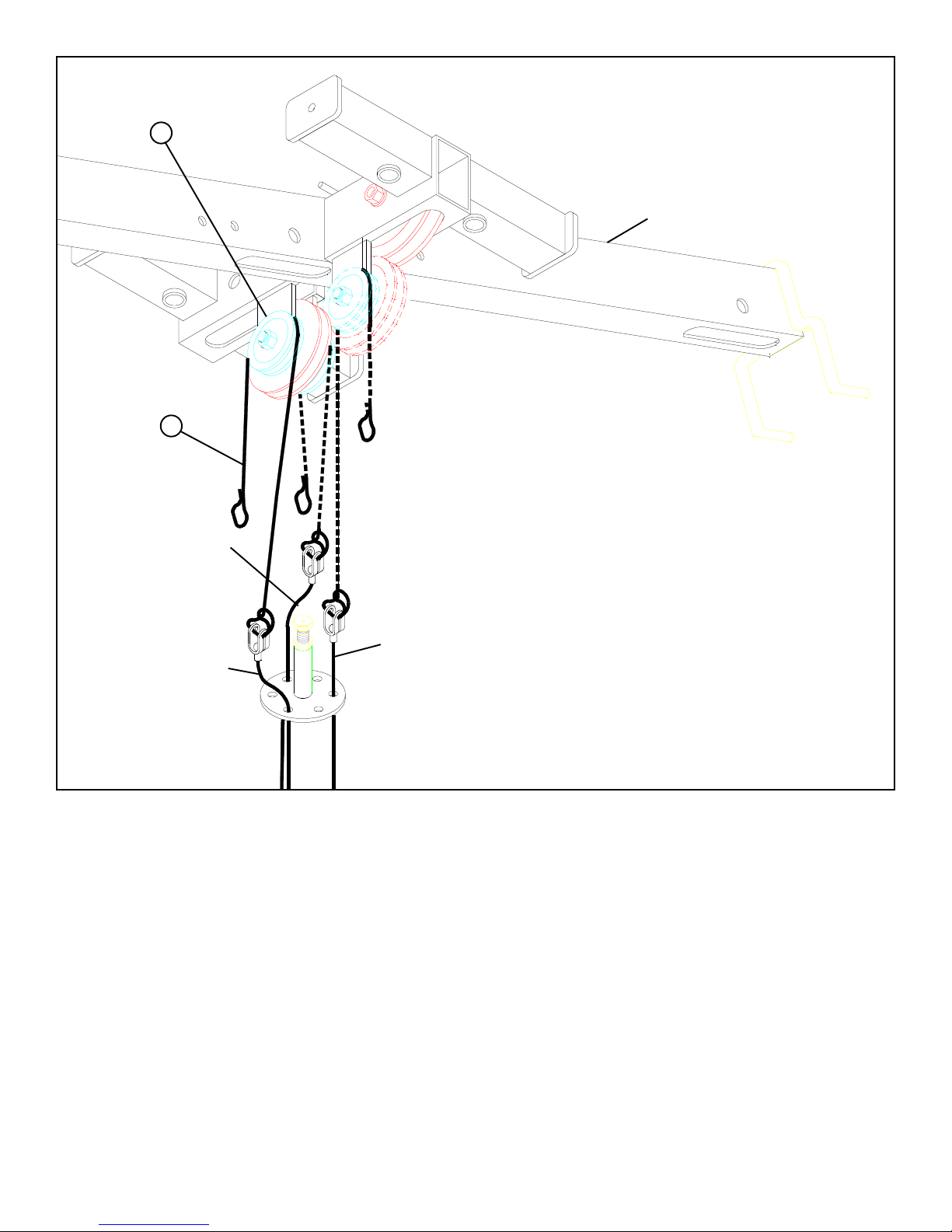
STEP 4
• Remove the three TENSION CORDS from the D-RING by
removing the three KEYHOLE CLEVIS, CLEVIS PINS,
and COTTER PINS as shown in 4.
FIGURE 4
CORD
CLEVIS PIN
COTTER PIN
3
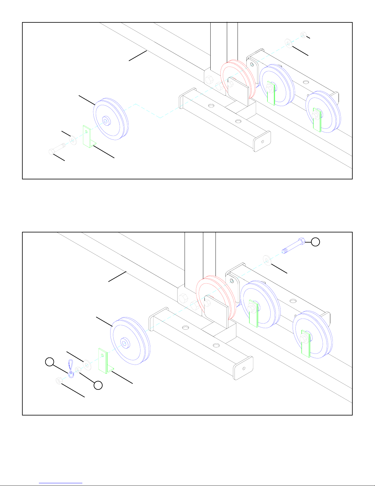
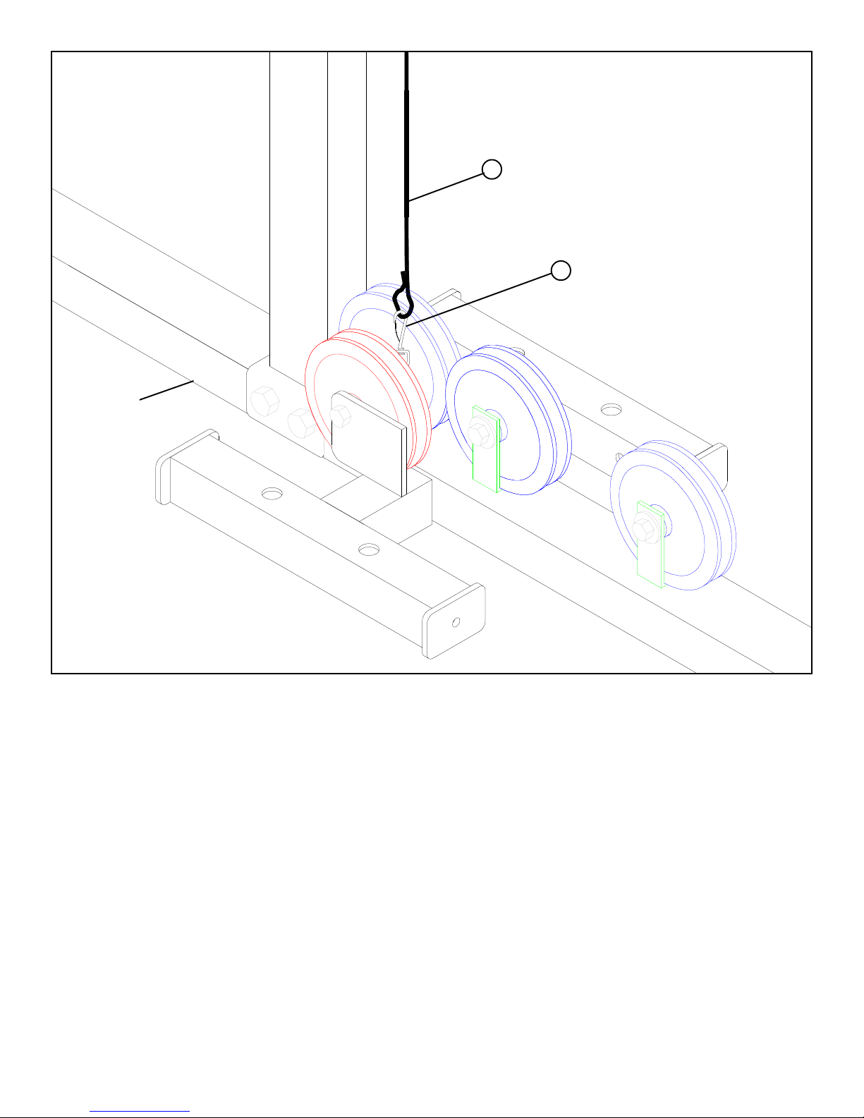
4-1/2” PULLEY
3/8” W ASHER
3/8” LOCK NUT
3/8” W ASHER
BASE
3/8” X 2” BOL T
2-7/8” L-BRACKET
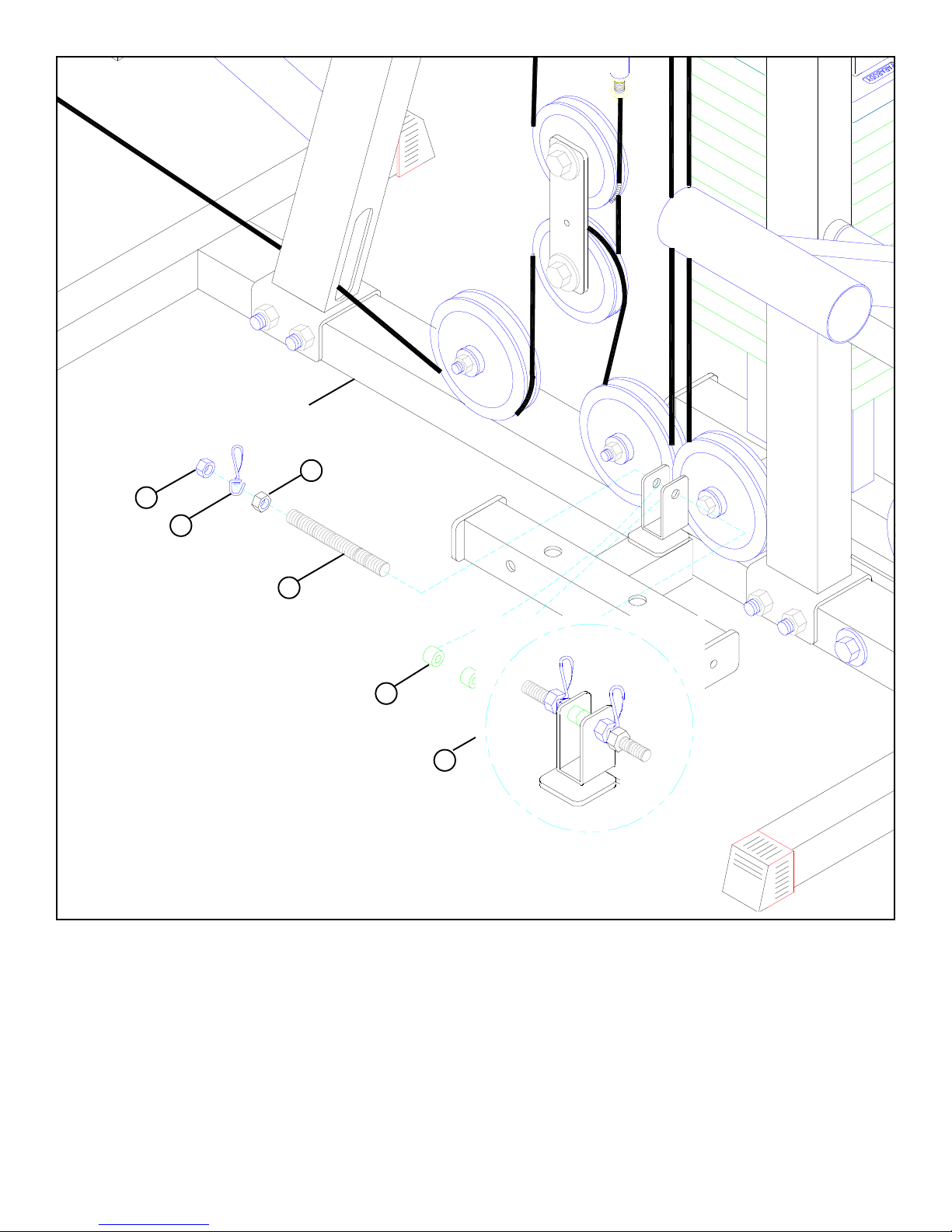
FIGURE 5
STEP 5
• Remove the 3/8 X 2” BOL T , two 3/8” WASHERS, one 2-7/8” L-BRACKETS, one 4-1/2” PULLEY, and one 3/8” LOCK NUT from the
upper flat on the BASE as shown in FIGURE 5.
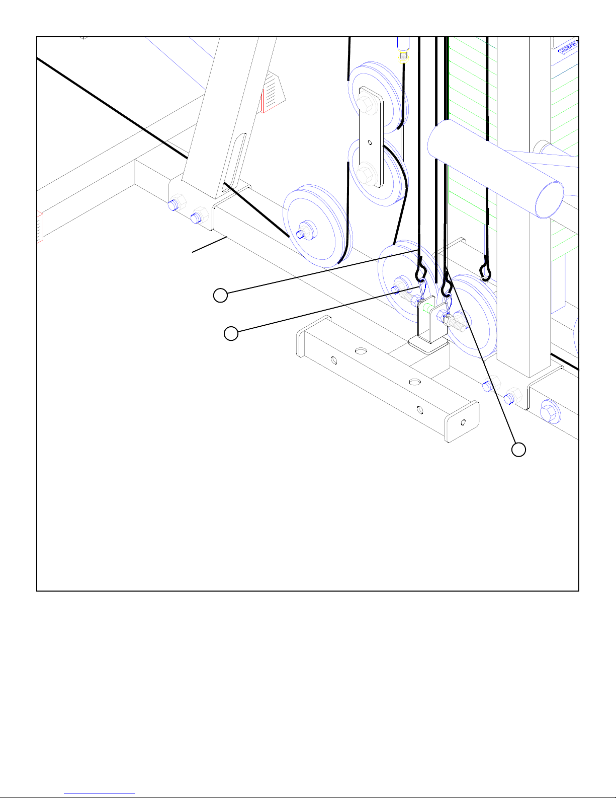
1 3/8 X 2-1/2”
3/8” W ASHER
BASE
4-1/2” PULLEY
3/8” W ASHER
3
8 HEX NUT
3/8” LOCK NUT
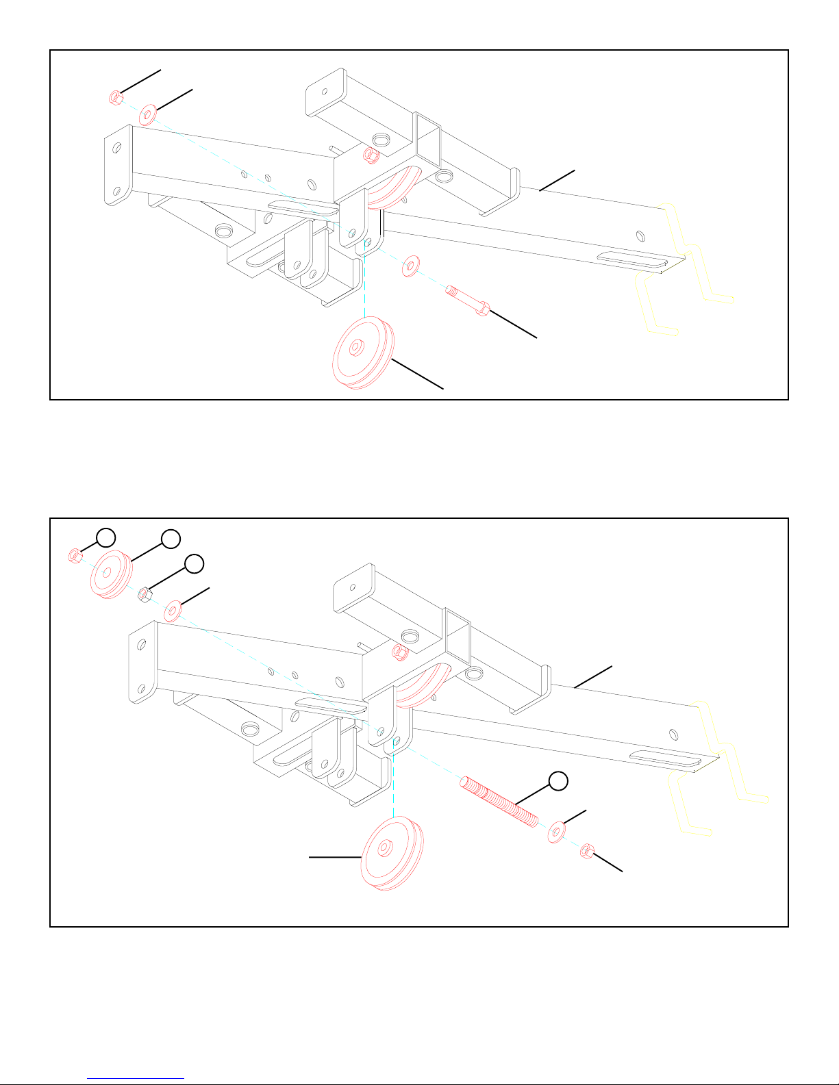
FIGURE 6
STEP 6
• SECURELY assemble the previously removed 4-1/2” PULLEY to the BASE using one 3/8 X 2-1/2” BOL T (1), two previously removed
3/8” WASHERS, one previously removed 2-7/8” L-BRACKET, one SWIVEL SNAP (3), one 3/8” HEX NUT (8), and one previously
removed 3/8” LOCK NUT . See FIGURE 6.
2-7/8” L-BRACKET
4
BASE
8 HEX NUT
7
3
9
10
3
8 HEX NUT
7
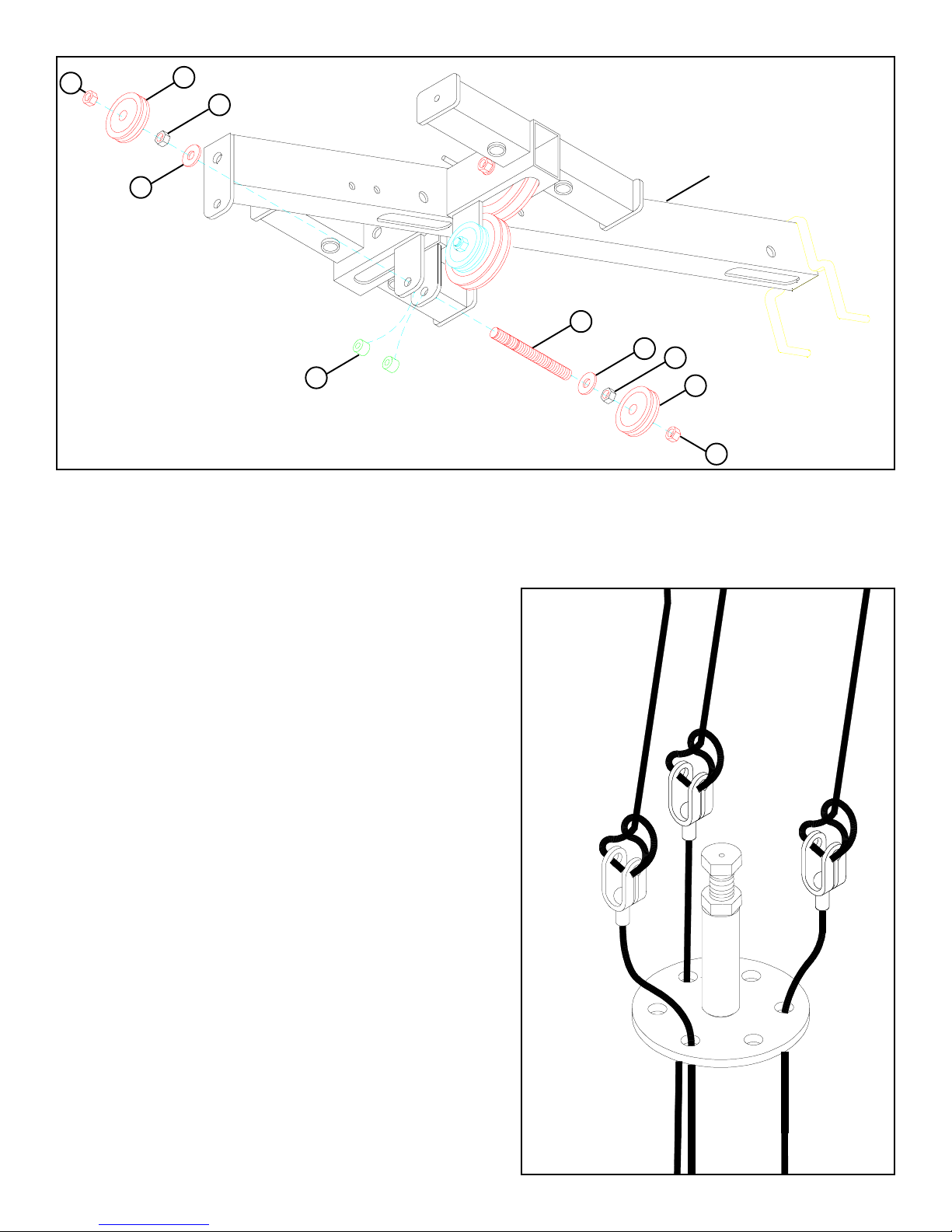
FIGURE 7
STEP 7
• Position two 3/8 X 1/2” SP ACERS (2) inside the bracket on the BASE and slide one 3/8” THREADED SHAFT (9) through the
bracket. See FIGURE 7.
• Assemble two 3/8” HEX NUTS (8), two SWIVEL SNAP (3), and two 3/8” LOCK NUTS (7) to the 3/8” THREADED SHAFT (9) as
shown in FIGURE 7.
5
3/8” LOCK NUT
3/8” W ASHER
TOP BOOM
3/8” X 2-1/4”
FIGURE 8
STEP 8
• Remove the 3/8 X 2-1/4” BOL T , two 3/8” WASHERS, one 3/8” LOCK NUT, and 3-1/2” PULLEY from the bracket on the TOP BOOM
as shown in FIGURE 8.
7
5
8 3/8” HEX NUT
3/8” W ASHER
3-1/2” PULLEY
TOP BOOM
9
3-1/2” PULLEY
FIGURE 9
STEP 9
• SECURELY assemble the previously removed 3-1/2” PULLEY to the bracket on the T OP BOOM using one 3/8” THREADED SHAFT
(9) , two previously removed 3/8” W ASHERS, one 2” PULLEY (5), one 3/8” HEX NUT (8), one previously removed 3/8” LOCK NUT ,
and one 3/8” LOCK NUT (7). See FIGURE 9.
3/8” W ASHER
3/8” LOCK NUT
6
7
5
8 3/8” HEX NUT
6
9
6
2
FIGURE 10
STEP 10
• Position two 3/8 X 1/2” SP ACERS (2) inside the rear bracket of the TOP BOOM and slide one 3/8” THREAD SHAFT (9) through the
bracket. See FIGURE 10.
• SECUREL Y assemble two 2” PULLEYS (5) to the rear bracket on the TOP BOOM using one 3/8” THREADED SHAFT (9), two 3/8”
W ASHERS, two 3/8” HEX NUTS (8), and two 3/8” LOCK NUTS (7) as shown in FIGURE 10.
TOP BOOM
8 3/8” HEX NUT
5
7
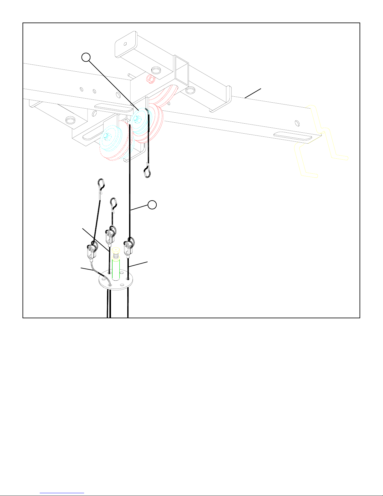
FIGURE 11
STEP 1 1
• Assemble three 72” ELASTIC CORDS to the KEYHOLE CLEVIS as
shown in FIGURE 11.
7
LEG EXT
CABLE
5
TOP BOOM
4
PRESS
LA T CABLE
CABLE
FIGURE 12
STEP 12
• Assemble the 22” ELASTIC CORD (4) from the PRESS CABLE around the 2” PULLEY (5) in the TOP BOOM as shown in FIGURE 12.
8
5
LEG EXT
CABLE
LA T CABLE
TOP BOOM
4
PRESS
CABLE
FIGURE 13
STEP 13
• Assemble the 22” ELASTIC CORD (4) from the LEG CABLE around the 2” PULLEY (5) in the TOP BOOM as shown in FIGURE 13.
9
5
4
LEG EXT
CABLE
TOP BOOM
PRESS
CABLE
LA T CABLE
FIGURE 14
STEP 14
• Assemble the 22” ELASTIC CORD (4) from the LAT CABLE around the 2” PULLEY (5) in the T OP BOOM as shown in FIGURE 14.
10
BASE
4 PRESS CABLE
3
FIGURE 15
STEP 15
• Assemble the ELASTIC CORD (4) from the PRESS CABLE to the SWIVEL SNAP (3) on the BASE as shown in FIGURE 15.
11
BASE
LEG CABLE 4
3
LA T CABLE 4
FIGURE 16
STEP 16
• Assemble the ELASTIC CORDS (4) from the LAT & LEG CABLES to the corresponding SWIVEL SNAPS (3) on the BASE as shown
in FIGURE 16.
12
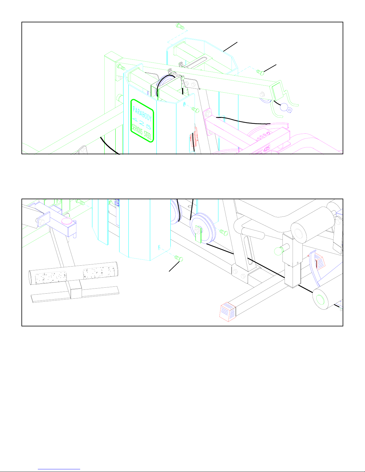
FIGURE 17
SHROUD
3/8” X 1” BUTTON
HEAD CAP SCREW
STEP 17
• SECUREL Y attach the top of the front SHROUD (with label) & rear SHROUD to the T OP BOOM using the four previously removed
3/8” X 1” BUTTON HEAD CAP SCREWS. See FIGURE 17.
3/8” X 1” BUTTON
HEAD CAP SCREW
FIGURE 18
STEP 18
• SECUREL Y attach the bottom of the front SHROUD (with label) & rear SHROUD to the T OP BOOM using the four previously removed
3/8” X 1” BUTTON HEAD CAP SCREWS. See FIGURE 18.
The installation of the 426103 Elastic Cord Conversion Kit is complete. If unsure of proper use of
equipment, call your local Parabody distributor or call the Parabody customer service department at
(800) 328-9714.
13
425103 with 832 LEG PRESS OPTION INSTALLED
• If the 445 WEIGHT STACK OPTION IS INSTALLED PROCEED T O P AGE 27.
• If the 832 LEG PRESS OPTION & 445 WEIGHT ST ACK OPTION ARE INST ALLED PROCEED T O P AGE 35.
FIGURE 3
CAP NUT
CORD
STEP 3
• Remove the 1/4” CAP NUTS and each TENSION CORD from the TOP BOOM as shown in FIGURE 3.
14
 Loading...