

ParaBody Serious Steel 400102 Assembly Manual
400102 HOME GYM
ASSEMBLY INSTRUCTIONS
1Part # 6873301 Revision: 8/30/00
IMPORTANT NOTES
WELCOME TO THE WORLD OF Serious steel!
Please note:
* Thank you for purchasing the Parabody 400102 Home Gym. Please read these
instructions thoroughly and keep them for future reference. This product must be assembled
on a flat, level surface to assure its proper function.
* We recommend cleaning your product (pads and frame) on a regular basis, using warm soapy
water. Touch-up paint can be purchased from your Parabody customer service representative
at (800) 328-9714.
There is a risk assumed by individuals who use this type of equipment. To minimize risk, please
follow these rules:
1. Inspect equipment daily . Tighten all loose connections and replace worn parts immediately.
Failure to do so may result in serious injury.
2. Do not allow minors or children to play on or around this equipment.
3. Exercise with care to avoid injury .
4. If unsure of proper use of equipment, call your local Parabody distributor or call the
Parabody customer service department at (800) 328-9714.
5. Consult your physician before beginning any exercise program.
T ools Required for Assembly
* Rubber mallet or hammer
* 3/4” wrench
* 9/16” wrench
* Ratchet with 3/4” and 9/16” sockets
* 5/32” Allen wrench
* Adjustable wrench
* T ape measure
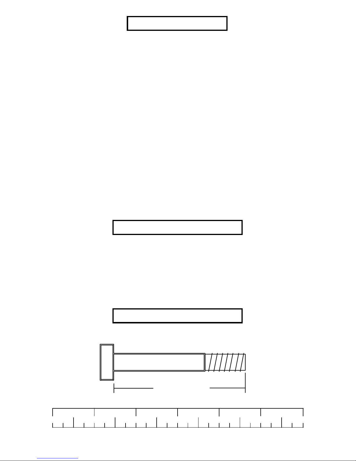
Bolt Length Ruler
NOTE: BOL T LENGTH IS MEASURED FROM THE UNDERSIDE OF THE HEAD OF THE BOLT.
BOL T LENGTH RULER:
1/2 1/2 1/2 1/2 1/2 1/2
0
1
BOLT LENGTH
2
345
2
6

PARTS LIST
KEY
PART #
6874903
1
6683302
2
6682803
3
6832203
4
6686802
5
6679503
6
6678603
7
6683103
8
6680402
9
6682103
10
6682503
11
6681303
12
6680202
13
6874502
14
6874603
15
6680903
16
6680803
17
6681902
18
6532903
19
6532803
20
6530203
21
6594702
22
6624402
23
6529702
24
6275302
25
6654302
26
6597402
27
6681502
28
6690901
29
6125102
30
6194601
31
6176201
32
6523401
33
6375902
34
3102909
35
3102924
36
3102933
37
3102922
38
3102904
39
3102905
40
3102906
41
3102910
42
3102943
43
3102917
44
3102937
45
3102901
46
3102949
47
3102802
48
3102801
49
3102804
50
3102501
51
33-1/2 X 9-1/2” BACK SEA T PAD
15-1/2 X 10-1/2” PEC SEA T PAD
15-3/4 X 15-1/2” LEG SEA T P AD
DESCRIPTION
FRAME SUPPOR T
WOLFF SLEEVE
WEIGHT ST ACK BASE
LEG CURL/EXTENSION
PULLEY BRACKET
ADJUSTMENT SLIDE
TOP BOOM
PRESS ARM
PRESS ARM LEVER
BASE
FRONT UPRIGHT
LEVER STOP
RECEIVING TUBE
BACK P AD SUPPORT
LEG SUPPORT
REAR UPRIGHT
BEARING HOUSING
PLA TE, 1/4 X 2 X 16-1/2”
PEC ARM RIGHT
PEC ARM LEFT
CENTER PULLEY BRACKET
FLOA TING PULLEY
SWIVEL PULLEY BRACKET
PEC CAM
LA T BAR
3/4 DIA X 11” SHAFT
3/4 OD X 16” TUBE
4 X 7” ROLLER P AD
PEC DEC ROLLER P AD
3/4 X 72-3/8” GUIDE ROD
WEIGHT ST ACK SP ACER
3/8 X 1” BOL T
3/8 X 1-3/4” BOL T
3/8 X 2” BOL T
3/8 X 2-3/4” BOL T
3/8 X 3” BOL T
3/8 X 3-3/4" BOL T
3/8 X 4" BOL T
1/2 X 3" BOL T
1/2 X 3-1/2" BOL T
1/2 X 4" BOL T
1/2 X 4-1/2" BOL T
3/8 X 1-1/4” BOL T
1/2 X 5-1/2” BOL T
3/8” LOCK NUT
1/2” LOCK NUT
1/2” LOW HT . NYLOCK NUT
3/8” W ASHER
QTY
1
1
1
1
1
1
1
1
1
1
1
1
1
1
1
1
1
2
1
1
1
2
1
2
1
1
1
1
2
3
8
2
2
2
4
8
4
10
6
2
4
10
3
2
2
1
2
29
10
8
30
KEY
3
52
53
54
55
56
57
58
59
60
61
62
63
64
65
66
67
68
69
70
71
72
73
74
75
76
77
78
79
80
81
82
83
84
85
86
87
88
89
90
91
92
93
94
95
96
97
98
99
100
PART #
3102502
3102503
3109602
6686301
6075906
6214401
6533501
6321201
3119201
3226301
3117901
3114407
3118401
3106803
6480301
6020601
6019701
3104901
6416601
6412001
3103801
3105401
6214501
6692601
6405201
6236701
6406401
3116201
6266001
6714601
6375801
6389701
6409101
3116001
6270501
6140701
3108002
3117401
6873801
6687201
6687001
6535601
6189501
6145801
6382301
6866601
6866801
6122702
6427101
DESCRIPTION
1/2” W ASHER
3/4” W ASHER
P AL NUT
1/2” DIA U-PIN
CHAIN
WEIGHT ST ACK PIN
CABLE RET AINING CLIP
CONTROL LEVER
8-32 X 3/16” SCREW
3/8” JOINT CONNECTOR CAP
E-RING
#10 FLA T WASHER
4” VINYL CAP
5/16” SET SCREW
3/8” FLANGE SP ACER
1/2” FLANGE BEARING
3/4” THRUST BEARING
3/4” FLANGE BEARING
1-3/4 X 3/4” PARAGLIDE
SPRING PIN ASSEMBLY
5/16” DIA SNAP LINK
ST ARLOCK COLLAR
WEIGHT PLA TE
3 X 2” END CAP
2” SQ. END CAP
1-3/4” SQ END CAP
HINGE T AB
3-1/2” PULLEY
WEIGHT ST ACK SHAFT
HEAD PLA TE
STRAP AB CRUNCH
LOW ROW BAR
STRAP ANKLE
1-1/4” BUMPER RUBBER
4 X 14” NON-SKID
1 X 1” GLIDE
WEIGHT ST ACK CUSHION
CAP PLUG
227-5/8” LEG EXT. CABLE
72-1/4” AB CABLE
103-1/2” LAT CABLE
77-5/8” PEC DEC CABLE
WEIGHT ST ACK LABELS
THUMBSCREW
WEIGHT PLA TE BUSHING 10CT
BOL T COVER CAP
BOL T COVER WASHER
3/8” X 1/2” SPACER
KEYHOLE CLEVIS
QTY
14
2
1
1
1
1
5
1
2
2
1
2
1
4
14
6
2
8
1
3
4
10
15
2
2
1
2
19
1
1
1
1
1
1
1
4
2
2
1
1
1
1
1
1
3
2
2
2
1
49
16
69
52
1/2 X 3” 42
66
3/8 X 2-3/4” 38
79
48
66
10
90
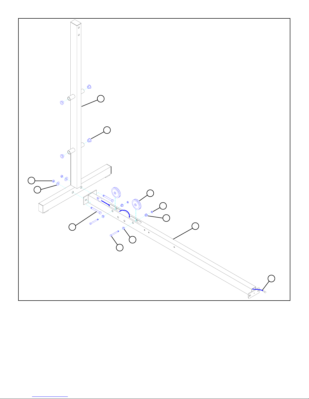
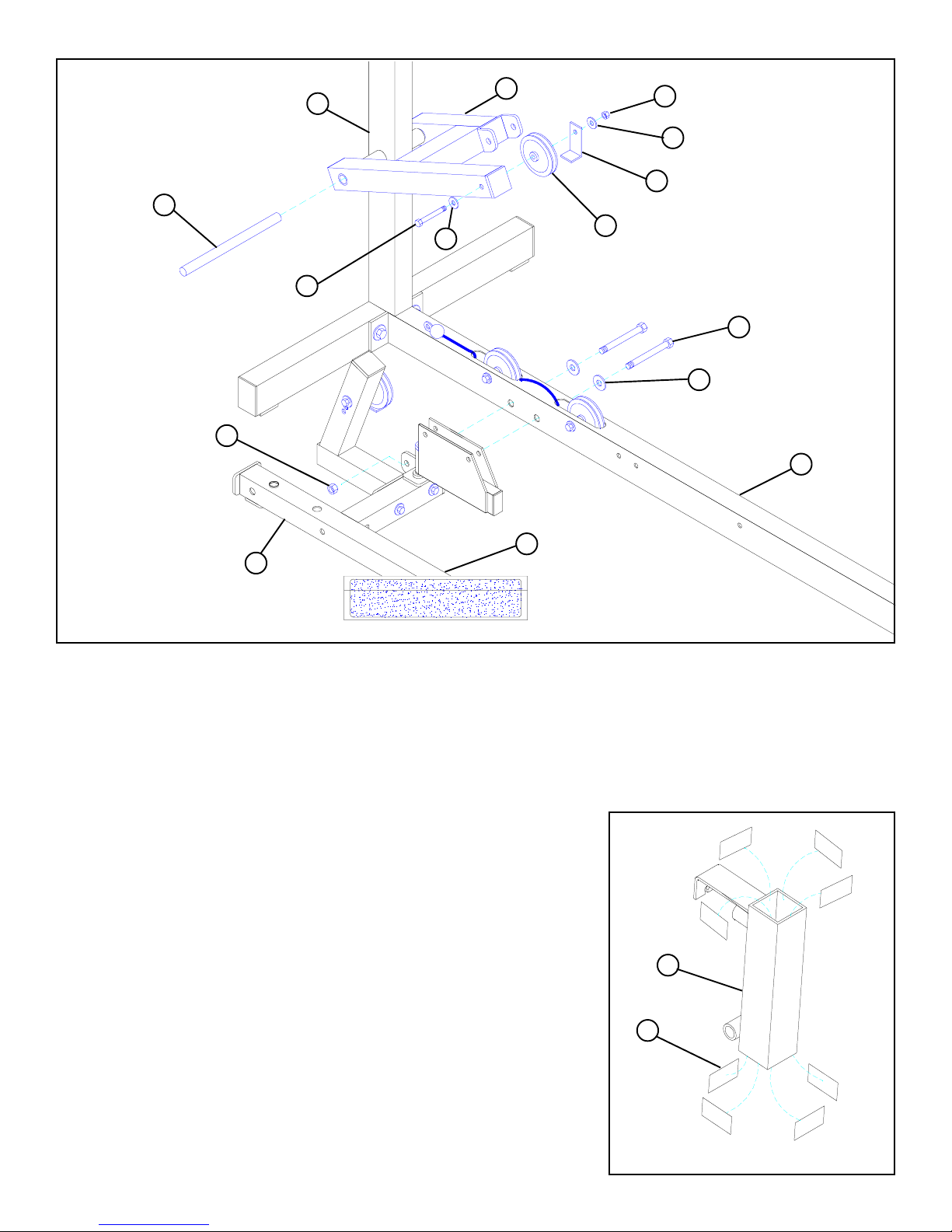
FIGURE 1
STEP 1
• Securely assemble REAR UPRIGHT (16 ) to BASE (10) using two 1/2 X 3" BOLTS (42), two 1/2" WASHERS (52), and two
1/2" LOCKNUTS (49).
• Slide LEG EXT . CABLE ASSEMBLY (90) through openings in BASE (10) as shown in FIGURE 1.
• Securely assembe two 3-1/2" PULLEYS (79) into BASE (10) using two 3/8 X 2-3/4" BOL TS (38), four 3/8" FLANGE SP ACERS (66),
and two 3/8" LOCKNUTS (48). (NOTE: Make sure LEG EXT . CABLE ASSEMBL Y (90) is r outed under PULLEYS and BOL TS.)
• Slide LEG EXT . CABLE ASSEMBLY (90) through the opening in the end of the BASE (10) as shown in FIGURE 1.
• Insert four 3/4" FLANGE BEARINGS (69) into tubes on REAR UPRIGHT (16) as shown in FIGURE 1
4
3/8 X 3-3/4” 40
51
12
79
58
48
51
50 1/2” LOW HEIGHT
49
3
1/2 1/2 1/2 1/2
0
52
23
42 1/2 X 3”
1
86
2
34
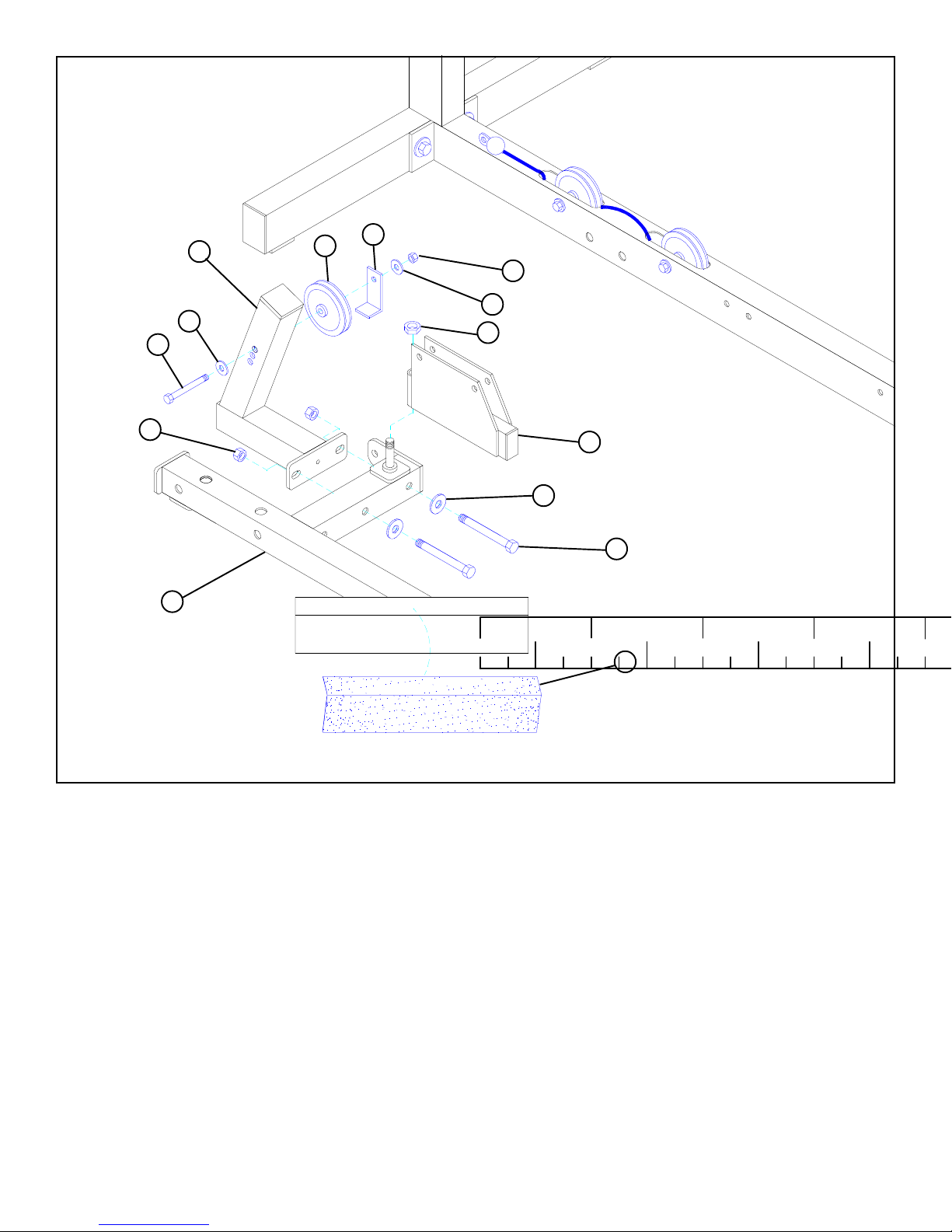
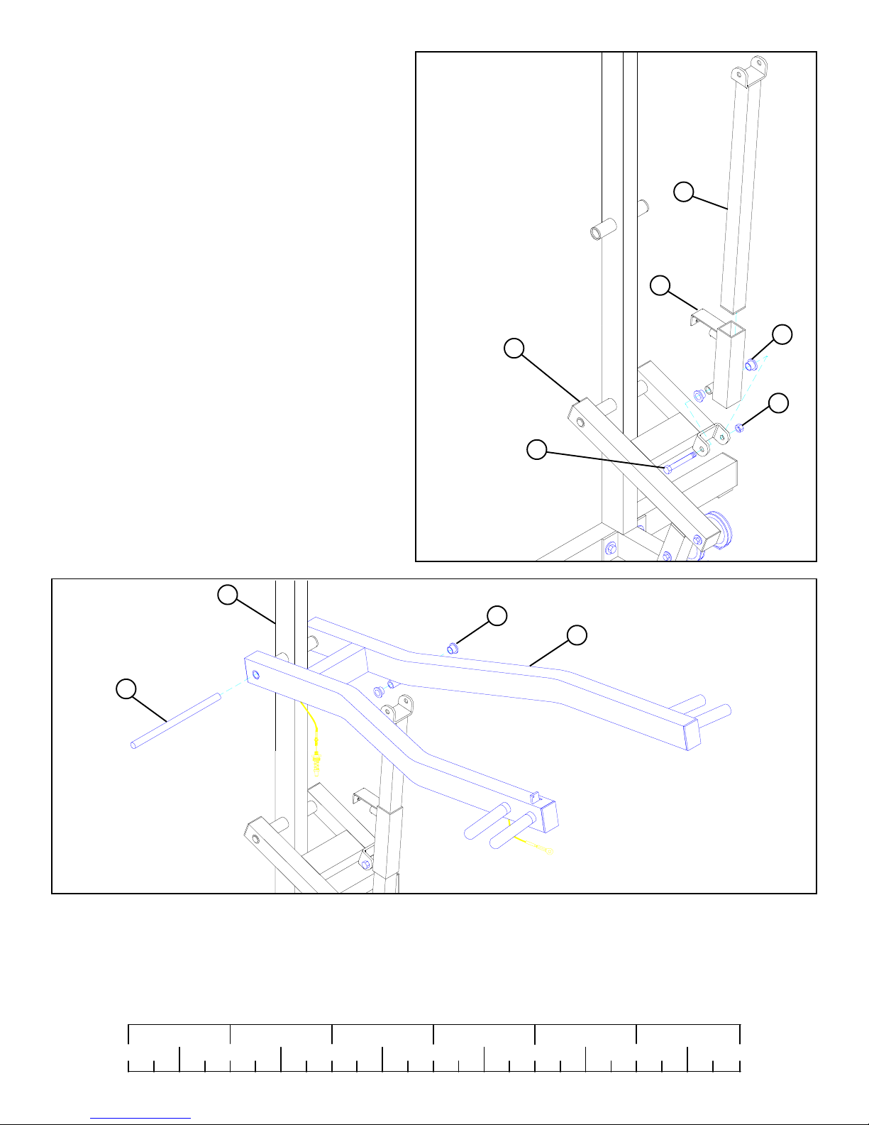
FIGURE 2
STEP 2
• Securely assemble one 3-1/2" PULLEY (79) to the top hole of the LEVER STOP (12) using one 3/8 X 3-3/4" BOLT (40), two 3/8"
WASHERS (51), one 2-3/8" RETAINING CLIP (58), and one 3/8" LOCKNUT (48). The extra holes in the LEVER STOP (12) are
to be used for cable adjustment.
• Securely attach LEVER STOP (12) to WEIGHT STACK BASE (3) using two 1/2 X 3" BOLTS (42), two 1/2" WASHERS (52),
and two 1/2" LOCKNUTS (49).
• Attach SWIVEL PULLEY BRACKET (23) to the WEIGHT STACK BASE (3) using one 1/2" LOW HEIGHT LOCKNUT
(50). (NOTE: Securely tighten, then back nut off 1/4 turn to allow the SWIVEL PULLEY BRACKET (23) to rotate freely.)
• Center 4 X 14" NON SKID STRIP (86) on WEIGHT STACK BASE (3) as shown in FIGURE 2.
5
29
3/8 X 3-3/4” 40
49
16
51
9
79
48
51
58
42 1/2 X 3”
52
10
86
3
FIGURE 3
STEP 3
• Securely attach WEIGHT STACK BASE (3) to BASE (10) using two 1/2 X 3" BOLTS (42), two 1/2" WASHERS (52), and
one 1/2" LOCKNUT (49).
• Slide one 3/4 DIA X 11" SHAFT (29) through PRESS ARM LEVER (9) & tube on REAR UPRIGHT (16). See FIGURE 3.
• Securely assembe one 3-1/2" PULLEY (79) to PRESS ARM LEVER (9) using one 3/8 X 3-3/4" BOLT (40), two 3/8"
WASHERS (51), one 2-3/8" RETAINING CLIP (58), and one 3/8" LOCKNUT (48).
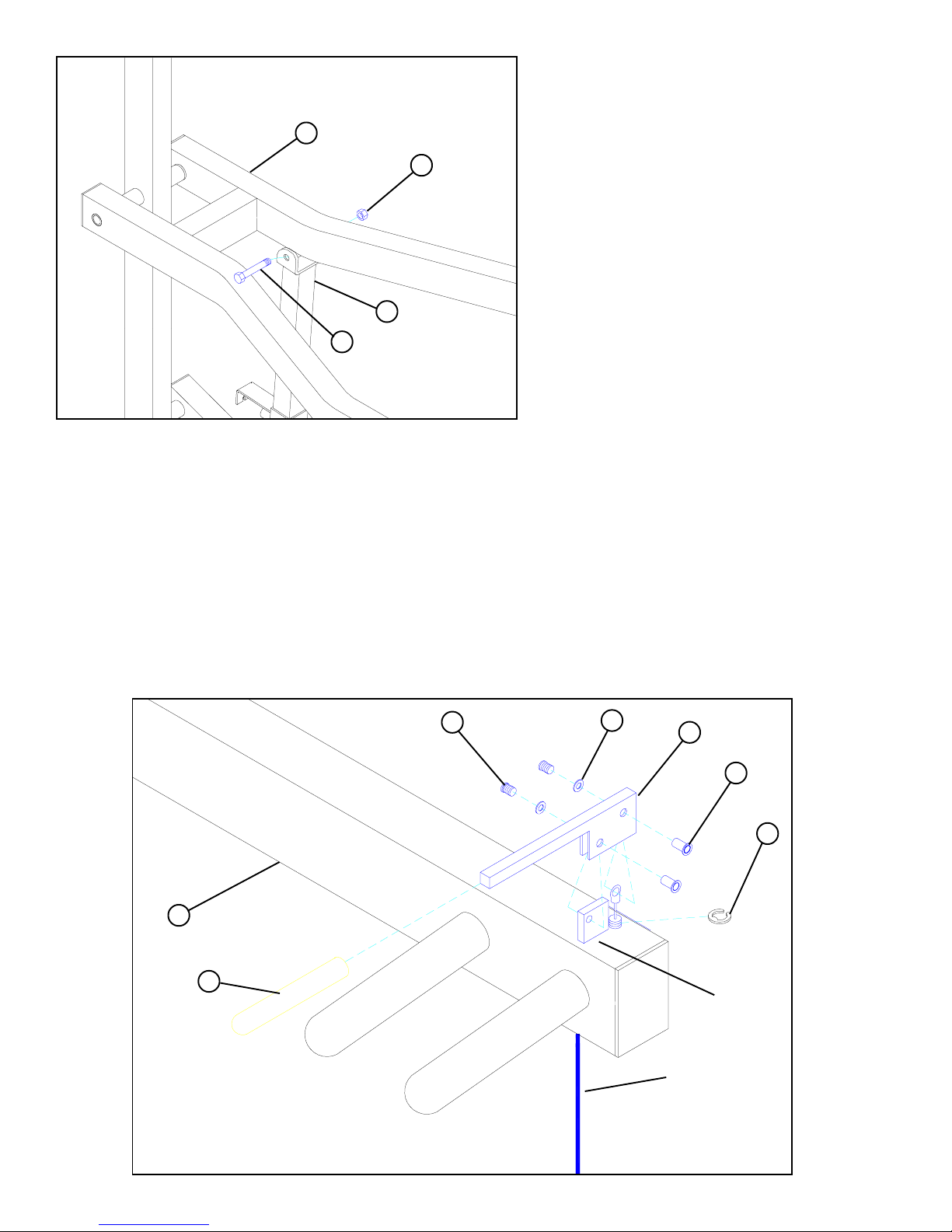
STEP 4
• Apply eight 1-3/4 x 3/4" PARAGLIDES (70) to the INSIDE of RECEIVING
TUBE (13) as shown in FIGURE 4. (NOTE: Throughly clean the inside
surface before attaching PARAGLIDES.)
13
70
FIGURE 4
6
STEP 5
• Insert two 1/2" FLANGE BEARINGS (67) into
RECEIVING TUBE (13).
• Attach RECEIVING TUBE (13) to PRESS ARM LEVER
(9) using one 1/2 X 3-1/2" BOLT (43), and 1/2" LOW
HEIGHT LOCKNUT (50). (NOTE: Securely tighten,
then back nut off 1/4 turn to allow the RECEIVING
TUBE (13) to rotate freely.)
6
• Insert the ADJUSTMENT TUBE (6) into the
RECEIVING TUBE (13) as shown in FIGURE 5.
16
29
9
1/2 X 3-1/2” 43
FIGURE 5
67
13
67
50
1/2”
LOW
HEIGHT
8
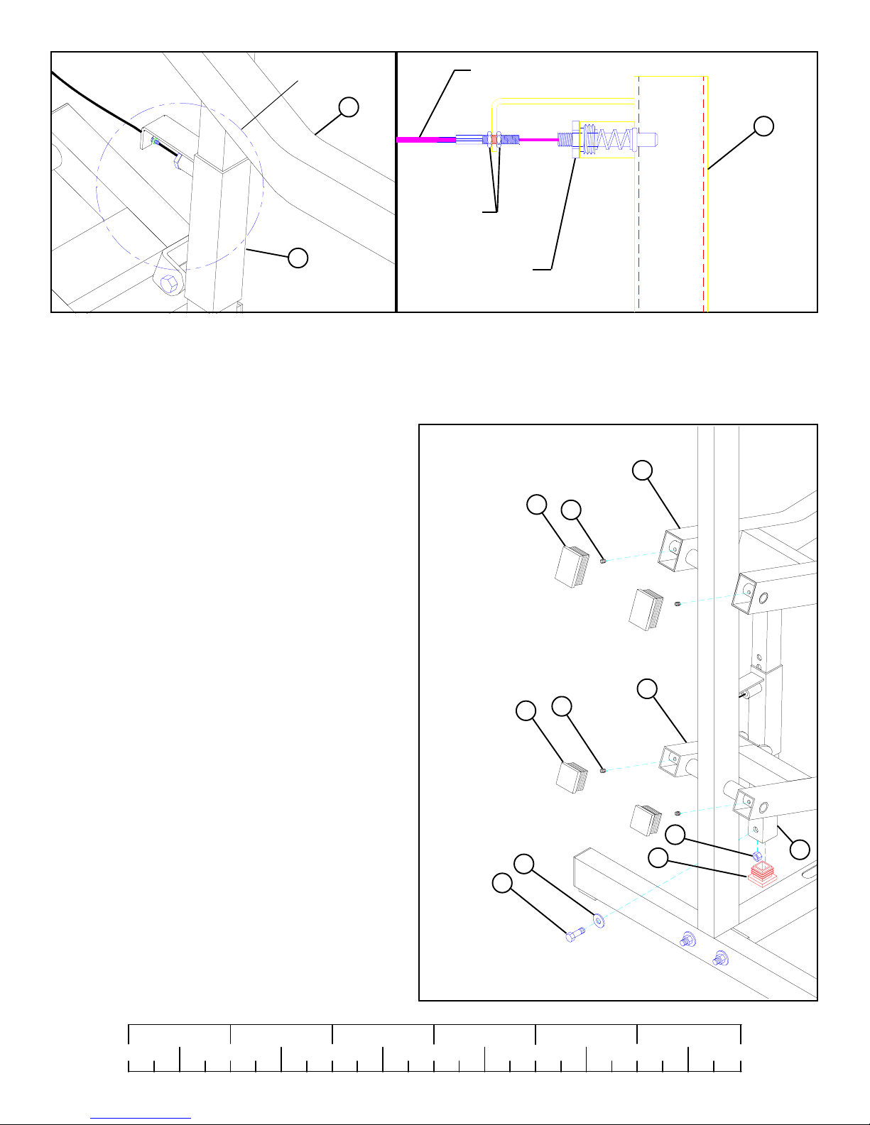
FIGURE 6
STEP 6
• Slide one 3/4 DIA X 11" SHAFT (29) through PRESS ARM (8) & tube on REAR UPRIGHT (16). See FIGURE 6.
• Insert two 1/2" FLANGE BEARINGS (67) into PRESS ARM (8).
1/2 1/2 1/2 1/2 1/2 1/2
0
1
2
345
7
6
8
43 1/2 X 3-1/2”
6
50
1/2” LOW
HEIGHT
STEP 7
• Attach ADJUSTMENT SLIDE (6) to PRESS ARM
(8) using one 1/2 X 3-1/2" BOLT (43), and 1/2" LOW
HEIGHT LOCKNUT (50). (NOTE: Securely
tighten, then back nut off 1/4 turn to allow the
PRESS ARM (8) to rotate freely.)
FIGURE 7
STEP 8
• Insert the PUSH/PULL CABLE through the bottom of the PRESS ARM (8) up to the CONTROL LEVER (59) and hold in place
with one E-RING (62) as shown in FIGURE 8.
• Securely assemble the PUSH/PULL CABLE to the CONTROL LEVER (59) using one 3/8 IN. JOINT CONNECTOR CAP (61),
one #10 FLAT WASHER (63), and one 8-32 X 3/16 IN. SCREW (60) as shown in FIGURE 8.
• Slide one 4” VINYL SLEEVE (64) over the CONTROL LEVER (59). Then SECURELY assemble the CONTROL LEVER (59) to
the TAB on the PRESS ARM (8) using one 3/8” JOINT CONNECTOR CAP (61), one #10 FLAT WASHER (63), and one 8-32 X
3/16 IN. SCREW (60) as shown in FIGURE 8.
60
8
64
63
59
61
62
TAB
FIGURE 8
PUSH/PULL
CABLE
8
DETAIL 9
8
PUSH/PULL
CABLE
13
1/4” NUTS
DO NOT OVERTIGHTEN!
13
FIGURE 9
STEP 9
Assemble the PUSH/PULL CABLE from the PRESS ARM (8) to the SPRING PIN HOUSING and to the L-BRACKET on the
RECEIVING TUBE (13) as shown on FIGURE 9 and DETAIL 9 using the following steps:
· Thread the first 1/4-28 IN. NUT to the bottom of the threaded end of the CABLE. Allow the other 1/4-28 IN. NUT to hang loose
on the exposed CABLE until the SPRING PIN ASSEMBLY is attached.
· Securely assemble the SPRING PIN ASSEMBLY to the
SPRING PIN BARREL. (!!! IMPORTANT !!! TIGHTEN
THE NUT OF THE SPRING PIN ASSEMBLY SECURELY)
· Swing the PRESS ARM (8) up until the SPRING PIN of the
PUSH/PULL CABLE engages in one of the adjustment
holes.
· Thread the second 1/4-28 IN. NUT onto the threaded end of
the CABLE, and cinch the two 1/4-28 IN. NUTS around the
flat.
· Use the extra thread on the end of the CABLE to adjust out
slack. ( !!! DO NOT ADJUST OUT TO FAR !!! AL-
WAYS ALLOW SPRING PIN ASSEMBLY TO FULLY
ENGAGE)
STEP 10
SPRING PIN
ASSEMBLY
76
75
DETAIL 9
8
65
9
65
• Securely tighten two 5/32” SET SCREWS (65) and insert
two 3 X 2” END CAPS (75) into the open ends of PRESS
ARM (8) as shown in FIGURE 10.
• Securely tighten two 5/32" SET SCREWS (65) and insert
two 2” SQ. END CAPS (76) into the open ends of PRESS
ARM LEVER (9) as shown in FIGURE 10.
• Securely tighten one 3/8 X 1” BOLT (35), one 3/8” WASHER
(51), and one 3/8” LOCKNUT (48) to the bottom of ADJUSTMENT SLIDE (6) as shown in FIGURE 10.
• Insert one 1-3/4” SQ. END CAP (77) into the end of ADJUSTMENT SLIDE (6) as shown in FIGURE 10.
1/2 1/2 1/2 1/2 1/2 1/2
0
1
48
6
3/8 X 1” 35
51
77
FIGURE 10
2
345
9
6
 Loading...