

Page 1
893104 PRO SYSTEM
ASSEMBLY INSTRUCTIONS
Part # 6817401 Revision:6/8/991
Page 2
IMPORTANT NOTES
WELCOME TO THE WORLD OF Serious steel!
Please note:
* Thank you for purchasing the Parabody 893104 PRO SYSTEM. Please read these instructions
thoroughly and keep them for future reference. This product must be assembled on a flat, level
surface to assure its proper function.
* We recommend cleaning your product (pads and frame) on a regular basis, using warm soapy
water. Touch-up paint can be purchased from your Parabody customer service representative
at (800) 328-9714.
There is a risk assumed by individuals who use this type of equipment. To minimize risk, please
follow these rules:
1. Inspect equipment daily . T ighten all loose connections and replace worn parts immediately.
Failure to do so may result in serious injury.
2. Do not allow minors or children to play on or around this equipment.
3. Exercise with care to avoid injury .
4. If unsure of proper use of equipment, call your local Parabody distributor or call the
Parabody customer service department at (800) 328-9714.
5. Consult a physician before beginning any exercise program.
T ools Required for Assembly
* 3/4” wrench
* 9/16” wrench
* Ratchet with 3/4” and 9/16” sockets
* Adjustable wrench
* T ape measure
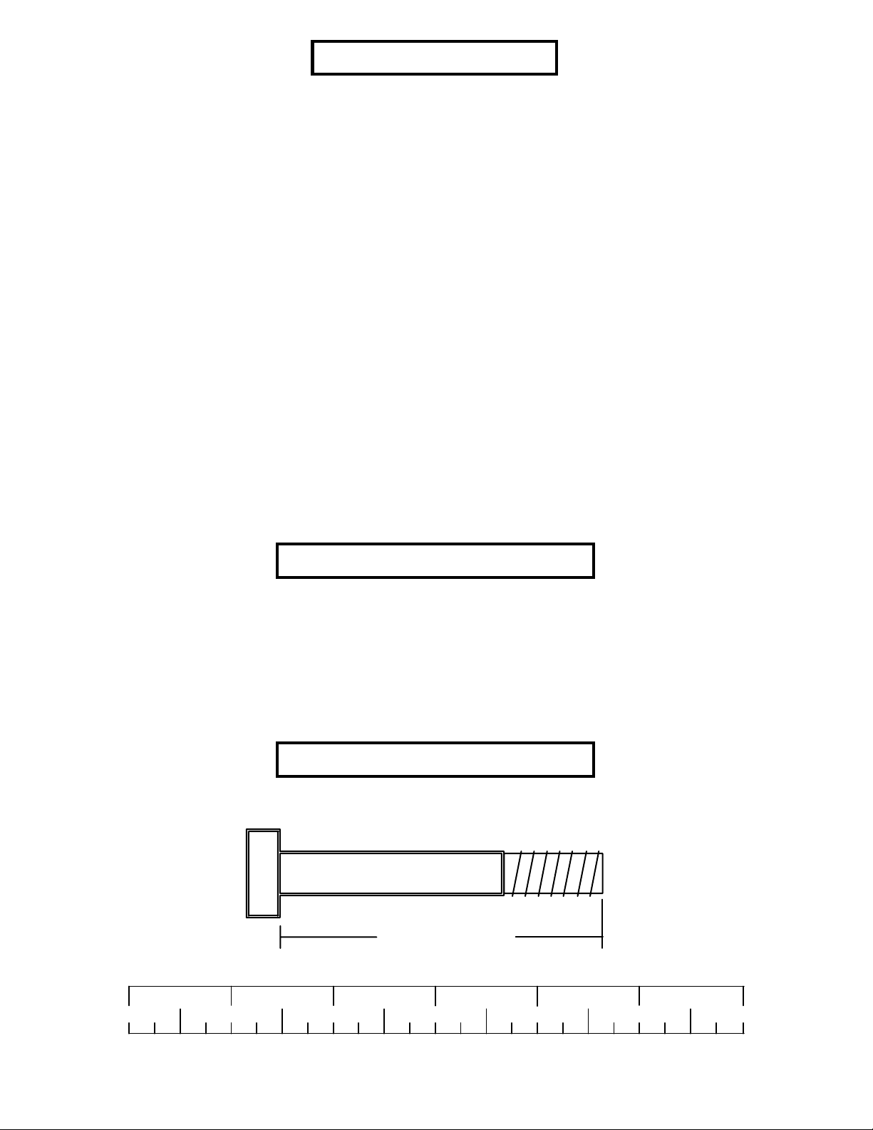
Bolt Length Ruler
NOTE: BOL T LENGTH IS MEASURED FROM THE UNDERSIDE OF THE HEAD OF THE BOLT.
BOL T LENGTH RULER:
1/2 1/2 1/2 1/2 1/2 1/2
0
1
BOLT LENGTH
2
345
2
6
Page 3
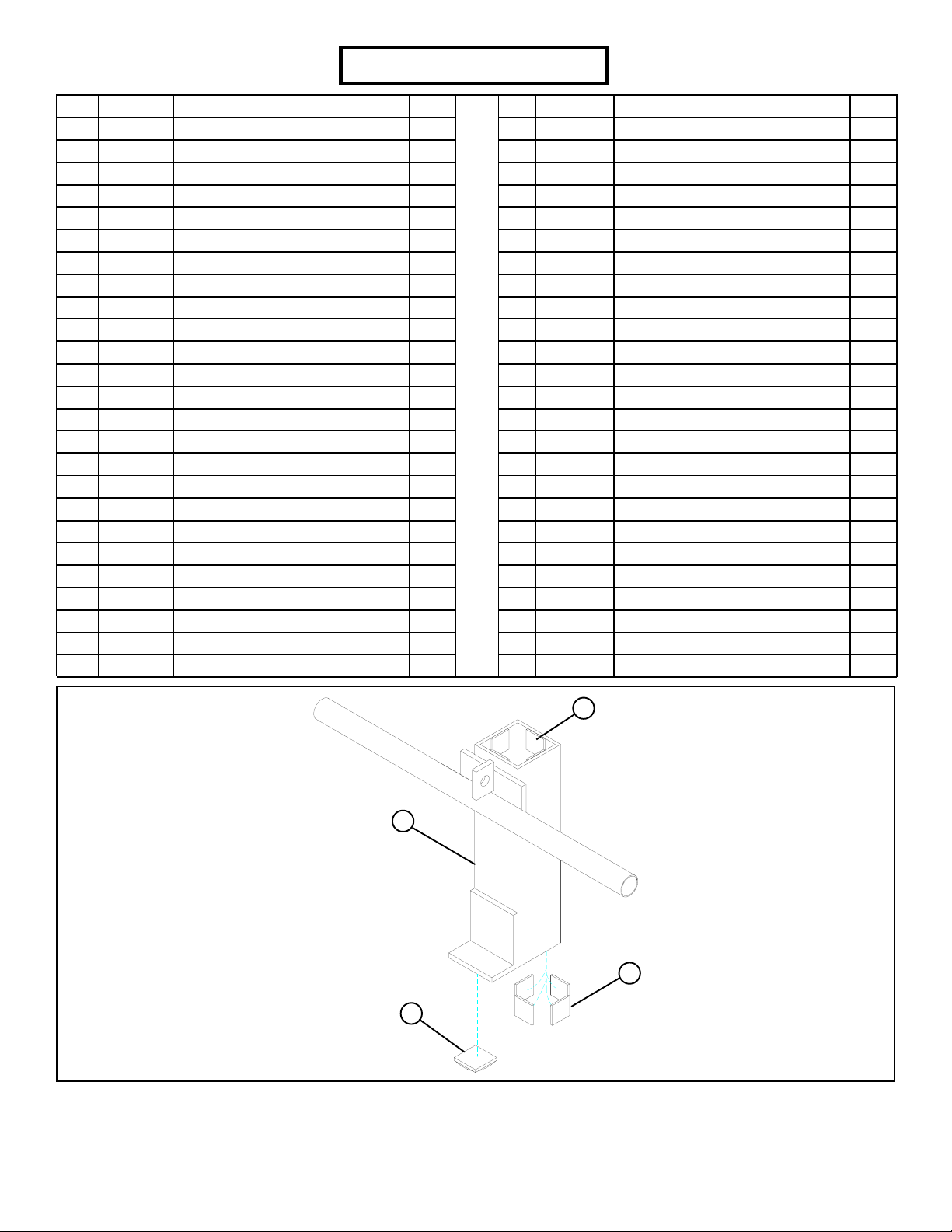
PARTS LIST
KEY
1
2
3
4
5
6
7
8
9
10
11
12
13
14
15
16
17
18
19
20
21
22
23
24
25
PART #
6816103
6815703
6815203
6814803
6815003
6816302
6798103
6801102
6275302
6274402
6807602
6807702
6546302
6812402
6194601
3116201
3116101
6816401
6692601
3103102
6140701
6405201
3116001
6817101
6811701
DESCRIPTION
TOP BOOM
UPRIGHT FRAME
KNEE SUPPORT
UPRIGHT SUPPOR T
FRONT UPRIGHT
FOOT PLA TE
UPPER CROSS SUPPORT
LA T BAR SUPPOR T
LA T BAR
LOW ROW BAR
LEFT SAFETY RAIL
RIGHT SAFETY RAIL
CARRIAGE
SMART RACK
4 X 7” ROLLER P AD
3-1/2” PULLEY
4-1/2” PULLEY
121-1/2” CABLE
3 X 2” END CAP
1 X 8” GRIP
1” SQ. GLIDE
2” SQ. END CAP
1-1/4” SQ. RUBBER BUMPER
1-5/8 X 5-1/2” NON-SKID STRIP
13-1/2 X 1-5/8” RUBBER STRIP
QTY
1
1
1
1
2
1
1
1
1
1
1
1
1
2
2
5
1
2
3
4
9
5
1
2
4
KEY
26
27
28
29
30
31
32
33
34
35
36
37
38
39
40
41
42
43
44
45
46
47
48
49
PART #
6824601
6542402
3105303
3105303
3102901
3102933
3102922
3102906
3102928
3102910
3102918
3102917
3102949
6480301
3102501
3102807
3102801
3102502
3102801
6606801
3105401
3103801
3108102
6075906
DESCRIPTION
3-1/4 X 1-3/4” GLIDE
1/2 X 3” VINYL CAP
3/16 X 1-3/4 X 5-1/4” PLA TE
9/16” CAP PLUG
3/8 X 1-1/4” BOL T
3/8 X 2” BOL T
3/8 X 2-3/4” BOL T
3/8 X 4” BOL T
1/2 X 2-1/2” BOL T
1/2 X 3” BOL T
1/2 X 3-1/4” BOL T
1/2 X 4” BOL T
1/2 X 5-1/2” BOL T
3/8” FLANGE SP ACER
3/8” W ASHER
3/8” LOW HEIGHT LOCK NUT
3/8” LOCK NUT
1/2” W ASHER
1/2” LOCK NUT
1/2” SPRING PIN ASSEMBLY
3/4” ST ARLOCK COLLAR
5/16” SNAP HOOK
1/4” QUICK LINK
12 LINK CHAIN
QTY
6
2
2
8
1
2
7
2
1
9
2
4
1
8
12
1
11
12
16
1
2
3
1
1
21
13
21
23
FIGURE 1
STEP 1:
• Apply eight 1” SQ. GLIDES (21) to the inside of the CARRIAGE (13) as shown in FIGURE 1.
• Attach one 1-1/4” SQ. RUBBER BUMPER (23) to the bottom of the CARRIAGE (13) as shown in FIGURE 1.
3
3
Page 4
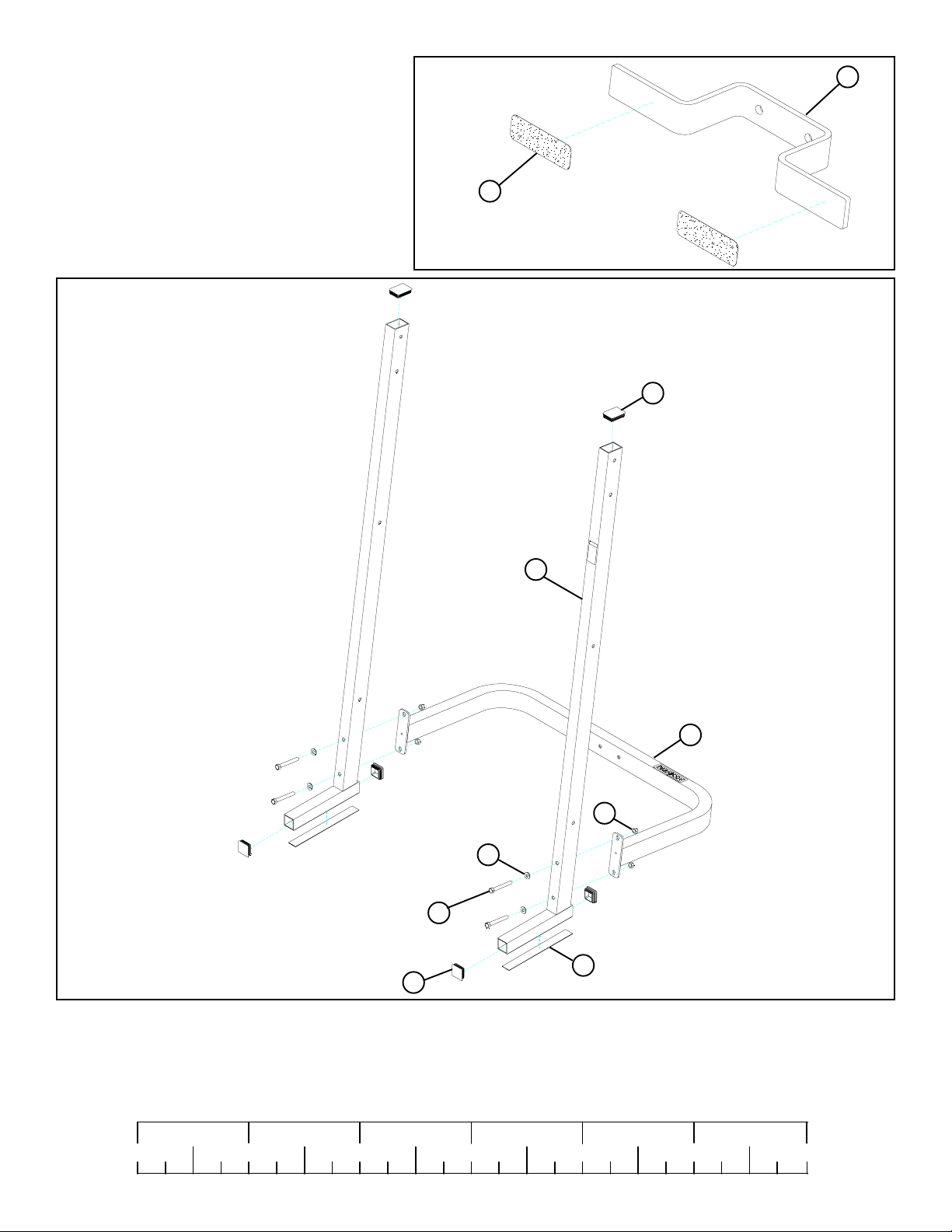
STEP 2:
• Attach two NON-SKID STRIPS (24) to the FOOT
PLA TE (6) as shown in FIGURE 2.
6
24
FIGURE 2
19
5
4
44
43
1/2 X 4” 37
25
FIGURE 3
22
STEP 3:
• Insert four 2” SQ. END CAPS (22) & two 3 X 2” END CAPS (19) to the ends of the FRONT UPRIGHTS (5) as shown in FIGURE 3.
• Assemble two 13-1/2 X 1-5/8” RUBBER STRIPS (25) to the bottom of the FRONT UPRIGHTS (5) as shown in FIGURE 3.
• LOOSEL Y assemble the FRONT UPRIGHTS (5) to the UPRIGHT SUPPOR T (4) using four 1/2 X 4” BOL TS (37), four 1/2” W ASHERS (43),
and four 1/2” LOCKNUTS (44) as shown in FIGURE 3.
1/2 1/2 1/2 1/2 1/2 1/2
0
1
2
345
4
6
Page 5

22
13
FIGURE 4
2
5
4
44
6
1/2 X 3-1/4” 36
STEP 4:
• LOOSEL Y assemble the FOOT PLA TE (6) and the UPRIGHT FRAME (2) to the UPRIGHT SUPPOR T (4) using two 1/2” X 3-1/4” BOL TS
(36) and two 1/2” LOCK NUTS (44) as shown in FIGURE 4.
• Slide the CARRIAGE (13) over the UPRIGHT FRAME (2) as shown in FIGURE 4.
• Insert one 2” SQ. END CAPS (22) to the end of the UPRIGHT FRAME (2) as shown in FIGURE 4.
5
Page 6

7
44
2
5
43
35 1/2 X 3”
14
44
43
FIGURE 5
1/2 X 3” 35
STEP 5:
• LOOSEL Y assemble the UPPER CROSS SUPPOR T (7) to the top set of holes of the FRONT UPRIGHTS (5) as shown in FIGURE 5 using
two 1/2 X 3” BOL TS (35), two 1/2” WASHERS (43), and two 1/2” LOCK NUTS (44).
• LOOSEL Y assemble the two SMAR T RACKS (14) to the outside of the FRONT UPRIGHTS (5) as shown in FIGURE 5 using six 1/2 X
3” BOL TS (35), four 1/2” W ASHERS (43), and six 1/2” LOCK NUTS (44).
1/2 1/2 1/2 1/2 1/2 1/2
0
1
2
345
6
6
Page 7

FIGURE 6
12
11
25
26
STEP 6:
• Attach six 3-1/4 X 1-3/4” GLIDES (26) to the LEFT & RIGHT SAFETY RAILS (11 & 12) as shown in FIGURE 6, using the
following steps:
• Thoroughly clean all surfaces where the 3-1/4 X 1-3/4” GLIDES (26) are to be attached.
• Remove the 3-1/4 X 1-3/4”” GLIDES (26) from the paper backing and firmly apply them flush with all shown surfaces.
• Attach two 13-1/2 X 1-5/8” RUBBER STRIPS (25) to the LEFT & RIGHT SAFETY RAILS (11 & 12) as shown in FIGURE 6.
12
5
12
11
FIGURE 7
STEP 7:
• Assemble the LEFT & RIGHT SAFETY RAILS (11 & 12) to the FRONT UPRIGHTS (5) as shown in FIGURE 7.
7
Page 8

FIGURE 8
1/2 X 2-1/2” 34
5
19
42
42
40
33 3/8 X 4”
1
35 1/2 X 3”
7
32 3/8 X 2-3/4”
2
44
43
STEP 8:
• LOOSEL Y assemble the T OP BOOM (1) to the UPRIGHT FRAME (2) using one 1/2 X 2-1/2” BOL TS (34), one 1/2 X 3” BOL T (35),
two 1/2” WASHERS (43), and one 1/2” LOCK NUT (44) as shown in FIGURE 8.
• LOOSEL Y assemble the TOP BOOM (1) to the UPRIGHT FRAME (2) using one 3/8 X 2-3/4” BOL TS (32) and one 3/8” LOCK NUT
(42) as shown in FIGURE 8.
• LOOSEL Y assemble the T OP BOOM (1) to the UPPER CROSS SUPPOR T (7) using two 3/8 X 4” BOLTS (33), four 3/8” W ASHERS
(40) and two 3/8” LOCK NUTS (42). See FIGURE 8.
• Insert one 3 X 2” END CAP (19) into the end of the TOP BOOM (1). See FIGURE 8.
* SECUREL Y TIGHTEN ALL LOOSE CONNECTIONS MADE UP TO THIS POINT!
FIGURE 9
1
3/8” LOW HEIGHT 41
8
27
32 3/8 X 2-3/4”
STEP 9:
• Slide two VINYL CAPS (27) over the LAT BAR SUPPOR T (8) as shown in FIGURE 9.
• SECURELY assemble the LA T BAR SUPPOR T (8) to the TOP BOOM (1) using one 3/8 X 2-3/4” (32) and one 3/8” LOW HEIGHT LOCK
NUT (41). See FIGURE 9.
1/2 1/2 1/2 1/2 1/2 1/2
0
1
2
345
8
6
Page 9

FIGURE 10
1
Make sure CABLE
is routed over bolt!
42
39
3/8 X 2-3/4” 32
16
18
STEP 10:
• Route one CABLE (18) through the TOP BOOM (1) as shown in FIGURE 10. (NOTE: Make sure CABLE is routed over bolt!)
• SECURELY assemble three 3-1/2” PULLEYS (16) into the slots of the TOP BOOM (1) using three 3/8 X 2-3/4” BOL TS (32), six 3/8”
FLANGE SP ACERS (39), and three 3/8” LOCK NUTS (42) as shown in FIGURE 10. (NOTE: Make sure the cable is routed over all the
pulleys.)
9
Page 10

FIGURE 11
1
42
40
16
28
31 3/8 X 2”
18
!IMPORTANT!
SECUREL Y
TIGHTEN
48
13
STEP 1 1:
• Attach the CABLE (18) from the TOP BOOM (1) to the CARRIAGE (13) using one 1/4” QUICK LINK (48) as shown in FIGURE 11.
(IMPORT ANT! Securely tighten QUICK LINK.)
• Place one 3-1/2” PULLEY (16) into the loop of the CABLE (18) below the second and third PULLEY of the TOP BOOM (1) as shown
in FIGURE 11.
• LOOSEL Y assemble two 3/16 X 1-3/4 X 5-1/4” PLA TES (28) to each side of the 3-1/2” PULLEY (16) using one 3/8 X 2” BOL T (31),
two 3/8” W ASHERS (40), and one 3/8” LOCK NUT (42). See FIGURE 11.
1/2 1/2 1/2 1/2 1/2 1/2
0
1
2
345
10
6
Page 11

FIGURE 12
2
42
39
40
17
18
32 3/8 X 2-3/4”
STEP 12:
• Route the end of the second CABLE (18) through the slot of the UPRIGHT FRAME (2) then SECURELY assemble one 4-1/2”
PULLEY (17) to the UPRIGHT FRAME (2) using two 3/8 X 2-3/4” BOLTS (32), two 3/8” FLANGE SP ACERS (39), two 3/8” W ASHERS (40), and two 3/8” LOCK NUTS (42). (NOTE: The CABLE (18) should be routed between the pulley and the retaining bolt as
shown in FIGURE 12.)
FIGURE 13
28
42
40
16
18
31 3/8 X 2”
STEP 13:
• W rap the CABLE (18) around one 3-1/2” PULLEY (16) and LOOSELY assemble it to the 3/16 X 1-3/4 X 5-1/4” PLATES (28) using one
3/8 X 2” BOL T (31), two 3/8” WASHERS (40), and one 3/8” LOCK NUT (42). See FIGURE 13.
11
Page 12

18
2
40
42
30 3/8 X 1-1/4”
FIGURE 14
STEP 14:
• SECUREL Y assemble the CABLE (18) to the plate on the UPRIGHT FRAME (2) using one 3/8 X 1-1/4” BOL T (30), two 3/8” WASHERS
(40), and one 3/8” LOCK NUT (42). See FIGURE 14.
• SECURELY tighten the bolts of the PULLEY BLOCK
44
46
15
3
ROUND
2
21
45
38 1/2 X 5-1/2”
FIGURE 15
STEP 15:
• Assemble two 4 X 7” ROLLER PADS (15) to the KNEE SUPPORT (3) using two ST ARLOCK COLLARS (46) as shown in FIGURE 15.
• SECURELY assemble the KNEE SUPPOR T (3) to the UPRIGHT FRAME (2) using one 1/2 X 5-1/2” BOL T (38) and one 1/2” LOCK
NUT (44). (NOTE: Do not overtighten this connection, the KNEE SUPPOR T should rotate freely .) See FIGURE 15.
• SECURELY assemble the SPRING PIN ASSEMBL Y (45) to the KNEE SUPPOR T (3) as shown in FIGURE 15.
• Attach one 1” SQ. GLIDE (21) to the UPRIGHT FRAME (2) where the round of the KNEE SUPPORT (3) makes contact.
1/2 1/2 1/2 1/2 1/2 1/2
0
1
2
345
12
6
Page 13

20
18
47
9
29
2
18
47
20
47
49
10
FIGURE 16
STEP 16:
• Slide two 1 X 8” GRIPS (20) on the LOW ROW BAR (10) and two 1 X 8” GRIPS (20) on the LAT BAR (9) as shown in FIGURE 16.
• Attach the LAT BAR (9) to the ball end of the upper CABLE (18) using one 5/16” SNAP HOOK (47) as shown in FIGURE 16.
• Attach the LOW ROW BAR (10) to the ball end of the lower CABLE (18) using one 12-LINK CHAIN (49) and two 5/16” SNAP
HOOKS (47) as shown in FIGURE 16.
• If the PEC DEC ATTACHMENT will not be assemble at this time, eight 9/16” CAP PLUGS (29) have been supplied to plug exposed
holes on the UPRIGHT FRAME (2) as shown in FIGURE 16.
Thank you for purchasing the Parabody 893104 PRO SYSTEM. If unsure of proper use of equipment, call
your local Parabody distributor or call the Parabody customer service department at (800) 328-9714.
13
 Loading...