

Panasonic of North America 96NKX TGA405 User Manual
Range Extender
Model No.
KX-TGA405
KX-TGA405C
Installation Guide for Range Extender
By installing this unit, you can extend the range of your phone system, to include
areas where reception was previously not available.
The unit extends the range in all directions, allowing several floors to be covered.
Important:
LThis unit is an accessory unit for use with the following series of Panasonic Digital
Cordless phones: KX-TG4051/KX-TG4071/KX-TG4051C
KX-TG4011/KX-TG4021/KX-TG4031/KX-TG4051/KX-TG4071/KX-TG6511/
LThis unit is pre-registered to the base unit.
KX-TG6521/KX-TG6531/KX-TG6541/KX-TG7531
LThis leaflet only describes the steps needed to install and use the unit. Refer to the
You must register this unit with your base unit before it can be used.
L
base unit’s operating instructions for the accessory information, important
This lea et only describes the steps needed to install and use the unit. Please read
L
information for safety, FCC information (for U.S.A. users only), and Industry
the base unit’s operating instructions for further details.
Canada Notices and other information (for Canada users only).
For best performance
Placement
LWe recommend installing the unit to a raised position (such as on a wall), which is
well within range of the base unit.
LAvoid positioning the unit close to objects that will interfere with reception, such as
thick walls, radiators, metal shelving, etc.
LFor maximum distance noise-free operation, place the unit away from electrical
appliances such as TV, radio, personal computer or other telephone equipment.
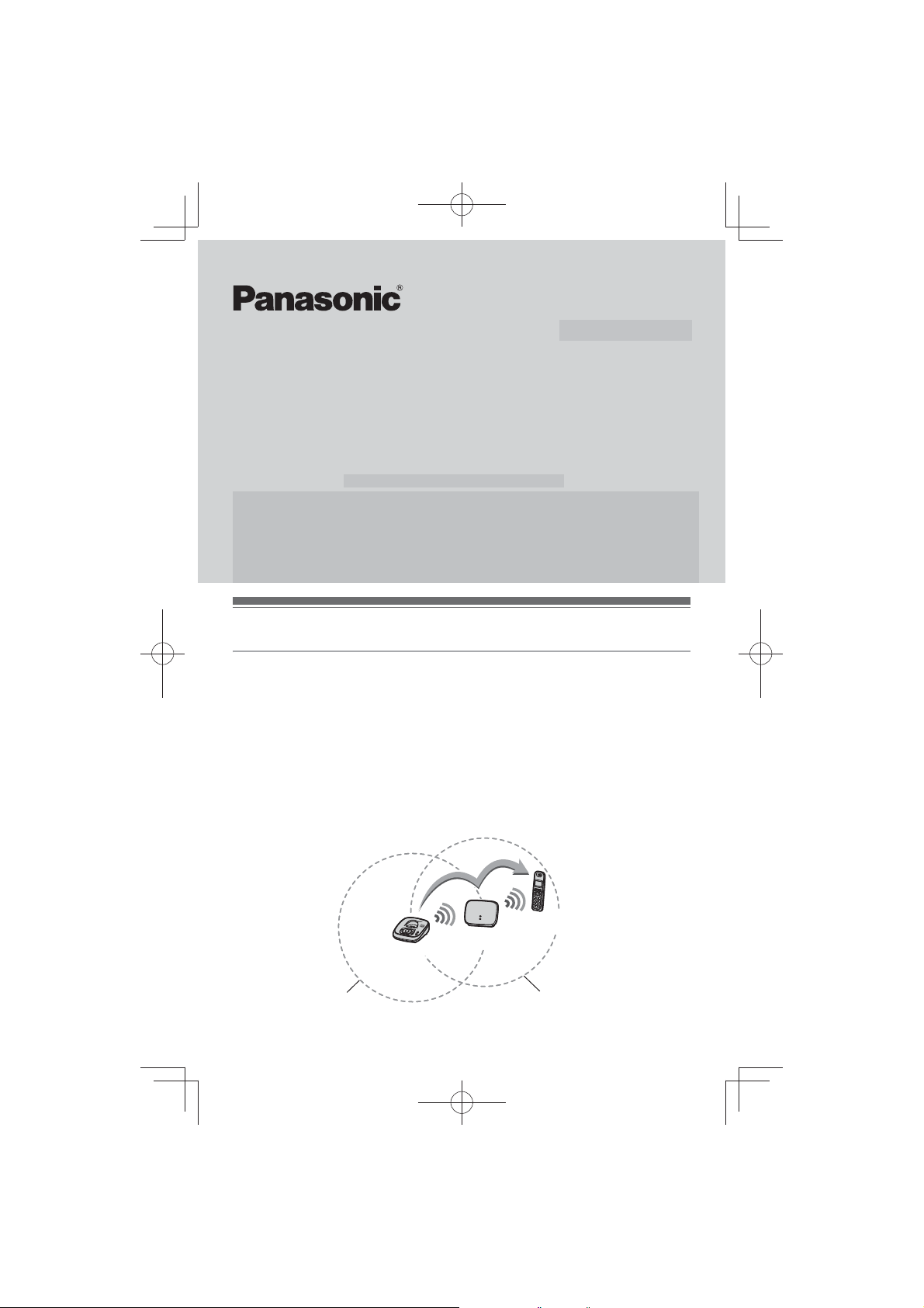
LKeep a minimum distance of 5 m between this unit and the base unit.
(The minimum distance may vary depending on the location.) If the unit is installed
near the base unit, the handset directly communicates with the base unit.
Base unit
Range extender
Handset
Range extender rangeBase unit range
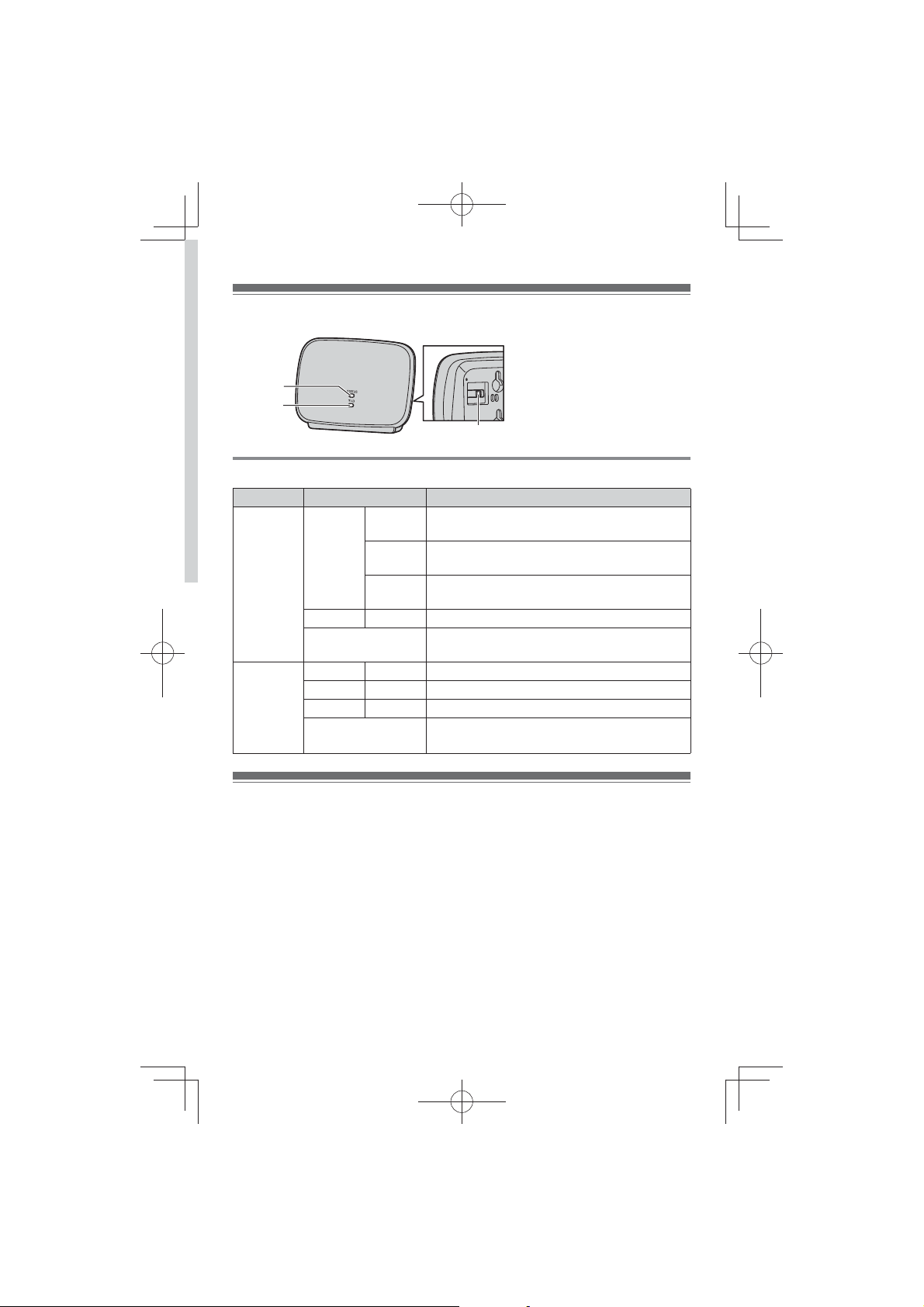
Controls
A STATUS indicator
B q indicator
A
B
C
Understanding the STATUS indicator and q indicator
Indicator Light status Meaning
STATUS
indicator
q
indicator
Green On LWithin base unit range. The unit is ready for
Flashing L1 handset is communicating with the base
Flashing
rapidly
Red On LOut of base unit range.
Off LThe power is off. (AC adaptor is not
Green On LSignal strength of the base unit is strong.
Amber On L Signal strength of the base unit is weak.
Red On LOut of base unit range.
Off LThe unit is not being used.
use.
unit through this unit.
L2 handsets are communicating with the base
unit through this unit.
connected properly.)
LThe power is off.
ID indicator
C PROGRAM
Installation
Base unit:
1
Press and hold [LOCATOR] for about 5 seconds until the registration tone
sounds.
The next step must be completed within 90 seconds.
L
_2_
2
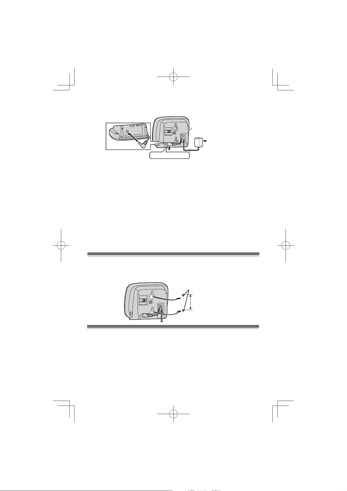
1 Connect the unit.
LUse only the supplied Panasonic AC adaptor PQLV219.
Hook
(120 V AC, 60 Hz)
Press plug firmly.
LWhen the unit is turned on, the STATUS indicator and q indicator light amber
for about 2 seconds.
2 Confirm that the STATUS indicator and q indicator light green. (The unit is
3
ready for use.)
LIf the indicators do not light green, re-position the unit in a place where the
indicators light green.
To stop the registration tone, press [LOCATOR] on the base unit.
L
Note:
LThe AC adaptor must remain connected at all times. (It is normal for the adaptor to
feel warm during use.)
LThe unit can support a maximum of 2 handsets at a time.
Wall Mounting
Drive the screws (not supplied) into the wall. Mount the unit, then slide it down.
Screws
37.0 mm
15
/32 inches)
(1
Specifications
N Standard: DECT 6.0 (Digital Enhanced Cordless Telecommunications 6.0)
N Frequency range: 1.92 GHz to 1.93 GHz
N RF transmission power: 115 mW (max.)
N Power source: 120 V AC, 60 Hz
N Power consumption: Standby: Approx. 0.0 W, Maximum: Approx. 0.0 W
_3_
1.0 W,
1.8 W
 Loading...