

Panasonic of North America 96NKX T0158, 96NKX T0155 User Manual
DECT 6.0 Cell Station Unit
Quick Installation Guide
Model No. KX-T0155/KX-T0158
Thank you for purchasing a Panasonic DECT 6.0 Cell Station Unit.
Please read this manual carefully before using this product and save this manual for future use.
Document Version: 2008-01

F.C.C. REQUIREMENTS AND RELEVANT INFORMATION
Privacy of communications may not be ensured when using the wireless systems.
CAUTION
Any changes or modifications not expressly approved by the party responsible for compliance could void the user's authority to operate this device.
Note
This equipment has been tested and found to comply with the limits for a Class B digital device, pursuant to Part 15 of the FCC Rules. These limits are designed to provide reasonable protection against harmful interference in a residential installation. This equipment generates, uses, and can radiate radio frequency energy and, if not installed and used in accordance with the instructions, may cause harmful interference to radio communications. However, there is no guarantee that interference will not occur in a particular installation. If this equipment does cause harmful interference to radio or television reception, which can be determined by turning the equipment off and on, the user is encouraged to try to correct the interference by one or more of the following measures:
•Reorient or relocate the receiving antenna.
•Increase the distance between the equipment and receiver.
•Connect the equipment to an outlet on a circuit different from that to which the receiver is connected.
•Consult the dealer or an experienced radio/TV technician for help.
Some wireless telephones operate at frequencies that may cause interference to nearby TVs and VCRs. To minimize or prevent such interference, the base of the wireless telephone should not be placed near or on top of a TV or VCR. If interference is experienced, move the wireless telephone further away from the TV or VCR. This will often reduce, or eliminate, interference.
CAUTION
To comply with FCC RF exposure requirements in an uncontrolled environment:
•This equipment must be installed and operated in accordance with provided instructions and a minimum 20 cm (8 in) spacing must be provided between antenna and all person's body (excluding extremities of hands, wrist and feet) during wireless modes of operation.
•This transmitter must not be co-located or operated in conjunction with any other antenna or transmitter.
Medical—consult the manufacturer of any personal medical devices, such as pacemakers, to determine if they are adequately shielded from external RF (radio frequency) energy. (The unit operates in the frequency range of 1920 MHz to 1930 MHz, and the output peak power level is less than 0.12 W.) Do not use the unit in health care facilities if any regulations posted in the area instruct you not to do so. Hospitals or health care facilities may be using equipment that could be sensitive to external RF (radio frequency) energy.
2 Quick Installation Guide

Table of Contents |
|
|
1 |
Overview.................................................................................................. |
4 |
2 |
Procedure Overview ............................................................................... |
7 |
3 |
Site Planning........................................................................................... |
9 |
4 |
Before Site Survey................................................................................ |
13 |
5 |
Site Survey ............................................................................................ |
18 |
6 |
After Site Survey................................................................................... |
22 |
7 |
Connecting a Cell Station to the PBX ................................................. |
23 |
8 |
Wall Mounting ....................................................................................... |
30 |
9 |
Troubleshooting.................................................................................... |
33 |
Quick Installation Guide |
3 |
|
|

1 Overview
1 Overview
Names and Locations
 Antennas
|
|
CS ID Number |
|
|
(ID: xxxxxxxxxx) |
LED |
|
|
LED Indications |
|
|
Indication |
Color |
Description |
STATUS |
Green/Red |
CS status indication |
|
|
• OFF: Power Off |
|
|
• Green ON: Stand-by (no active calls) |
|
|
• Slow Green Flashing (60 times per minute): Talk (active calls) |
|
|
• Moderate Green Flashing (120 times per minute): Busy |
|
|
• Red ON: Fault (includes Initialization) |
|
|
• Red Flashing (60 times per minute): Out of Service/Starting up |
|
|
CS status indication during the site survey |
|
|
• Red ON: The CS is connected to an AC adaptor/battery box. |
|
|
• Red Flashing (60 times per minute): The CS is connected to the |
|
|
PBX. |
Maximum Number of Calls
Cell Stations (CSs) determine the area covered by the wireless system. The number of calls that can be made simultaneously through each CS varies depending on the model, as follows:
Cell Station |
|
Maximum Calls |
|
Compatible Portable Station |
|
|
|
|
|
KX-T0155 |
2 |
|
• |
KX-TD7685 |
|
|
|
• |
KX-TD7695 |
KX-T0158 |
8 |
|
||
|
|
|
||
|
|
|
|
|
Note
For more details about the Portable Station (PS), refer to the Operating Instructions of the PS.
4 Quick Installation Guide

1 Overview
Maximum Number of CSs Supported by PBX
The following number of CSs can be supported by each PBX.
PBX |
|
Connected via |
Maximum Number |
||
|
|
|
|||
|
KX-T0155 |
KX-T0158 |
|||
|
|
|
|||
|
|
|
|
|
|
KX-TAW848 |
• |
Hybrid Ports |
4 |
- |
|
• |
HLC card |
||||
|
|
|
|||
|
|
|
|
|
|
KX-TDA50 |
• |
Super Hybrid Ports |
|
|
|
• |
HLC card |
8 |
- |
||
(with Additional AC Adaptor) |
|||||
• |
DLC card |
|
|
||
|
|
|
|||
|
|
|
|
|
|
KX-TDA100/KX-TDA200 |
• |
DHLC card |
32 |
- |
|
• |
DLC card |
||||
|
|
|
|||
|
|
|
|
|
|
KX-TDA600 |
• |
DHLC card |
128 |
- |
|
• |
DLC card |
||||
|
|
|
|||
|
|
|
|
|
|
KX-TDE100/KX-TDE200 |
• |
DHLC card |
32 |
16 |
|
• |
DLC card |
||||
|
|
|
|||
|
|
|
|
|
|
Required Distances between Equipment
Maintain the distances listed below between equipment in order to prevent noise, interference or the disconnection of a conversation. (The distance may vary depending on the environment.)
Equipment |
Distance |
|
|
CS and office equipment such as a computer, telex, fax |
More than 2 m (6 ft 7 in) |
machine, etc. |
|
|
|
CS and PS |
More than 1 m (3 ft 3 in) |
|
|
Each CS |
More than 3 m (10 ft) |
|
|
Each PS |
More than 0.5 m (1 ft 8 in) |
|
|
PBX and CS |
More than 2 m (6 ft 7 in) |
|
|
If multiple CSs cover the same area, the phone connection may become noisy or the number of possible simultaneous calls with PSs may decrease due to interference between the CSs. For details, refer to "5 Site Survey—Testing the Radio Signal Strength".
The required distance between CSs may vary depending on the environment of the installation site and conditions in which the wireless system is used. Conduct a site survey to determine the appropriate distance.
RF Specification
Item |
Description |
|
|
Radio Access Method |
MultiCarrier TDMA-TDD |
|
|
Frequency Band |
1920 MHz to 1930 MHz |
|
|
Number of Carriers |
5 |
|
|
Quick Installation Guide |
5 |
|
|

1 Overview
Item |
Description |
|
|
Carrier Spacing |
1728 kHz |
|
|
Bit Rate |
1152 kbps |
|
|
Carrier Multiplex |
TDMA, 24 (Tx12, Rx12) slots per frame |
|
|
Frame Length |
10 ms |
|
|
Modulation Scheme |
GFSK |
|
|
|
Roll-off factor=0.5 50 % roll-off in the transmitter |
|
|
Data Coding for Modulator |
Differential Coding |
|
|
Voice CODEC |
32 kbps ADPCM (CCITT G.726) |
|
|
Transmission Output |
Peak 125 mW |
|
|
CAUTION
•The CS should be kept free of dust, moisture, high temperature (more than 40 °C [104 °F]), low temperature (less than 0 °C [32 °F]), and vibration, and should not be exposed to direct sunlight.
•The CS should not be placed outdoors (use indoors).
•The CS should not be placed near high-voltage equipment.
•The CS should not be placed on a metal object.
6 Quick Installation Guide
2 Procedure Overview
2 Procedure Overview
When connecting the wireless system, use extreme care in conducting the site survey. An incorrectly performed site survey can result in poor service area, frequent noise, and disconnection of calls.
IMPORTANT
•When installing the DECT 6.0 wireless system in an area where another wireless system (2.4 GHz) is already installed, it is necessary to reconduct the site survey to find the optimum position for the CS. If you install the new CS in the same position as the old CS, it may result in a poor service area, frequent noise, and disconnection of calls.
•In this case, it is necessary to perform system initialization. For details about the system initialization procedure, refer to "Starting the PBX" in the Installation Manual for your PBX.
1.Investigate the installation site
Refer to "3 Site Planning".
a.Obtain a map of the CS installation site.
b.Identify the service area required by the user on the map.
c.Plan the location of each CS, taking account of distance, building materials, etc.
2.Prepare for site survey
Refer to "4 Before Site Survey".
a.Check and assign the CS ID number to the PS.
b.Assign a channel number to each CS by setting the DIP switches on the back of the CS.
c.Supply electricity to each CS using an AC adaptor/battery box or by connecting them to the PBX.
d.Install each CS temporarily as planned.
Notes
•Install at least 2 m (6 ft 7 in) above the floor.
•Place the antennas so that they are pointing in directions that are 90 degrees apart (for antenna diversity).
3.Conduct the site survey
Refer to "5 Site Survey".
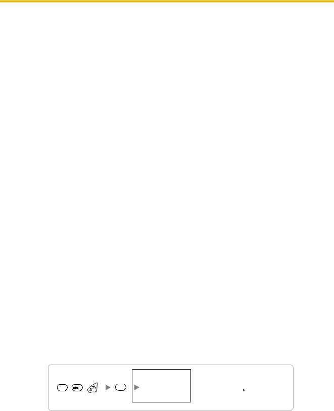
a.Test the radio signal strength using the PS.
Confirm that the radio signal strength level is "12" near the CS.
Using the KX-TD7685/KX-TD7695
1 |
9 |
Press 1, 9, and POWER for more than 2 seconds.
0
To survey |
|
Display example: |
|
||
specific channel |
|
RADIO STRENGTH |
|
RADIO STRENGTH |
|
Channel No. |
|
|
|
||
|
|
<<< MEASURING >>> |
|
L:12 0000/0100 |
|
|
|
|
|
CH0 SLOT:06 SYNC |
|
|
|
|
|
|
CS-ID:9005301234 |
0 to 4 |
|
|
|
||
|
|
|
|
||
|
|
|
|
|
|
|
|
|
|
|
|
b.By walking away from the CS with the PS, check the radio signal strength. The radio signal strength weakens as you walk away from the CS.
c.Map the CS coverage area at radio signal strength levels "3" and "8".
d.Make sure that adjacent CS coverage areas meet where the radio signal strength level is "7" to "9".
Quick Installation Guide |
7 |
|
|

2 Procedure Overview
e.Make sure that the radio signal strength level is greater than "3" at any location within the service area required by the user.
4.Finish the site survey
Refer to "6 After Site Survey".
a.Turn off the PS.
b.Stop supplying power, and return all DIP switches of each CS to the OFF position.
5. Connect the CS and PS to the PBX and test the operation
Refer to "7 Connecting a Cell Station to the PBX".
a.Connect the CSs to the PBX.
b.Register the PSs to the PBX.
c.Walk around the service area while having a conversation using a registered PS. If noise is frequent or conversations disconnect, relocate the CSs or install an additional CS.
6. Mount the CS on the wall
Refer to "8 Wall Mounting".
a.If there are no problems in testing, mount the CS on the wall.
8 Quick Installation Guide

3 Site Planning
3 Site Planning
Choosing the best site for the CS requires careful planning and testing of essential areas. The best location may not always be convenient for installation. Read the following information before installing the unit.
Understanding Radio Waves
Characteristics of Radio Waves
The transmission of radio waves and the CS coverage area depend on the structure and materials of the building.
Office equipment, such as computers and fax machines, can interfere with radio waves. Such equipment may create noise or interfere with the performance of the PS.
The illustration below shows the special transmitting patterns of radio waves.
1.Radio waves are reflected by objects made of materials such as metal.
2.Radio waves are diffracted by objects such as metallic columns.
3.Radio waves penetrate objects made of materials such as glass.
1. Reflection
CS
 Column
2. Diffraction |
3. Penetration |
Relationships between Radio Waves and Building Structure and Materials
•The CS coverage area is affected more by the building materials and their thickness than the number of obstacles.
•Radio waves tend to be reflected or diffracted by conductive objects and rarely penetrate them.
•Radio waves tend to penetrate insulated objects and are rarely reflected by them.
•Radio waves penetrate thin objects more than thick objects.
•The table below shows the transmission tendency of radio waves when they reach objects made from various materials.
Quick Installation Guide |
9 |
|
|

3 Site Planning
Object |
Material |
Transmission Tendency |
|
|
|
|
|
Wall |
Concrete |
The thicker they are, the less radio waves |
|
|
|
|
penetrate them. |
|
|
|
|
|
|
Ferroconcrete |
Radio waves can penetrate them, but the more iron |
|
|
|
there is, the more radio waves are reflected. |
|
|
|
|
Window |
Glass |
Radio waves usually penetrate them. |
|
|
|
|
|
|
|
Glass with wire net |
Radio waves can penetrate them, but tend to be |
|
|
|
reflected. |
|
|
|
|
|
|
Glass covered with heat- |
Radio waves are weakened considerably when |
|
|
resistant film |
they penetrate windows. |
|
|
|
|
Floor |
Ferroconcrete |
Radio waves can penetrate them, but the more iron |
|
|
|
|
there is, the more radio waves are reflected. |
|
|
|
|
Partition |
Steel |
Radio waves are reflected and rarely penetrate |
|
|
|
|
them. |
|
|
|
|
|
|
Plywood, Glass |
Radio waves usually penetrate them. |
|
|
|
|
Column |
Ferroconcrete |
Radio waves can penetrate them, but the more iron |
|
|
|
|
there is, the more radio waves tend to be reflected |
|
|
|
or diffracted. |
|
|
|
|
|
|
Metal |
Radio waves tend to be reflected or diffracted. |
|
|
|
|
Cabinet |
Steel |
Radio waves are usually reflected or diffracted, |
|
|
|
|
and rarely penetrate them. |
|
|
|
|
|
|
Wood |
Radio waves can penetrate them, but they are |
|
|
|
weakened. |
|
|
|
|
10 Quick Installation Guide
3 Site Planning
CS Coverage Area
The example below shows the size of the coverage area of 1 CS if it is installed in an area with no obstacles.
Note
Radio signal strength levels are measured during the site survey (refer to "5 Site Survey").
A
B
Gray Zone: Conversation will be intermittent
ACoverage Area
Radio signal strength level is greater than "3".
(About 35 m to 50 m [115 ft to 164 ft])
BGood Coverage Area Radio signal strength level is greater than "8". (About 20 m to 30 m [65 ft to 98 ft])
Good sound quality can be maintained.
COut of Service:
Cannot make/receive calls
Radio Signal Strength Levels
Level: 11 to 12 |
Better |
Level: 08 to 10 |
Good |
Level: 03 to 07 |
May receive noise |
Level: 01 to 02 |
Receives noise easily or disconnects |
Level: 00 |
Out of range |
|
|
Site Survey Preparation
1.Obtain a map and investigate the installation site.
a.Check the obstacles (e.g., shelves, columns, and partitions).
b.Check the materials of the structures (e.g., metal, concrete, and plywood).
c.Check the layout and dimensions of the room, corridor, etc.
d.Write down the above information on the map.
2.Examine the service area required by the user on the map, referring to the following example.
a.Draw the coverage area around a CS. Extend the coverage area 20 m to 50 m (65 ft to 164 ft) in each direction, depending on the materials of the building structures and obstacles in the installation site. Note that a CS cannot be installed outside a building.
b.If 1 CS cannot cover the entire service area, install additional CSs as required. Overlap the coverage areas of adjacent CSs.
Where CS coverage areas overlap, the PS will start call handover to the next CS if the signal from
Quick Installation Guide |
11 |
|
|
 Loading...