

Panasonic KX MC6020 - Color Laser - All-in-One, KX-MC6020HX KX-FAP317E, X-FAP317X, KX-FAB318E, X-FAP318X Service Manual

© Panasonic Communications Co., Ltd. 2008. Unauthorized copying and distribution is a violation of law.
ORDER NO. KMF0811207CE
Colour Laser Multi-Function Printer
Model No. KX-MC6020HX
KX-FAP317E/X
(Optional lower input tray)
KX-FAB318E/X
(Optional Automatic duplex
unit)
(for Eastern Europe)

2
KX-MC6020HX
TABLE OF CONTENTS
PAG E PAG E
1 Safety Precautions -----------------------------------------------3
1.1. For Service Technicians ---------------------------------3
1.2. AC Caution---------------------------------------------------3
1.3. Personal Safety Precautions ----------------------------4
1.4. Service Precautions ---------------------------------------5
2Warning--------------------------------------------------------------5
2.1. About Lead Free Solder (PbF: Pb free) --------------5
2.2. Discarding of P. C. Board --------------------------------6
2.3. Insulation Resistance Test ------------------------------6
2.4. Battery Caution ---------------------------------------------6
2.5. Laser Beam and Fuser Unit Section ------------------7
3 Specifications ------------------------------------------------------8
4 General/Introduction---------------------------------------------9
4.1. Optional Accessories--------------------------------------9
4.2. Translation Lists --------------------------------------------9
4.3. Precautions for Shipping -------------------------------17
5Features------------------------------------------------------------ 30
5.1. General Features----------------------------------------- 30
5.2. Hardware Requirements for Multi-Function
Software ---------------------------------------------------- 30
6 Technical Descriptions---------------------------------------- 31
6.1. Connection Diagram------------------------------------- 31
6.2. General Block Diagram --------------------------------- 32
6.3. Main Board Section-------------------------------------- 35
6.4. NCU Section----------------------------------------------- 53
6.5. ITS (Integrated Telephone System) and
Monitor Section ------------------------------------------- 54
6.6. CIS Control Section-------------------------------------- 55
6.7. Motor Drive Section-------------------------------------- 56
6.8. Timing Chart and Waveform of Scanner
Motors------------------------------------------------------- 65
6.9. Timing Chart and Waveform of Optional Unit
Motors------------------------------------------------------- 69
6.10. Fan Section ------------------------------------------------ 70
6.11. Solenoid Driver Section -------------------------------- 72
6.12. LSU (Laser Scanning Unit) Section ----------------- 73
6.13. Sensors and Switches Section ----------------------- 78
6.14. Operation Board Section ----------------------------- 101
6.15. LCD Section --------------------------------------------- 102
6.16. Heat Lamp Control Circuit --------------------------- 103
6.17. HVU (High Voltage Power Supply Board)
Section ---------------------------------------------------- 107
6.18. Main Board Section-------------------------------------112
6.19. PSU (Low Voltage Power Supply Board)
Section -----------------------------------------------------116
6.20. Mechanical Operation----------------------------------117
7 Location of Controls and Components---------------- 134
7.1. Overview ------------------------------------------------- 134
7.2. Control Panel-------------------------------------------- 135
8 Installation Instructions------------------------------------- 136
8.1. Installation------------------------------------------------ 136
8.2. Connections --------------------------------------------- 150
9 Operating Instructions -------------------------------------- 152
9.1. YOUR LOGO ------------------------------------------- 152
10 Test Mode-------------------------------------------------------- 154
10.1. Test Functions------------------------------------------- 154
11 Serv ice Mode --------------------------------------------------- 157
11.1. Programming and Lists ------------------------------- 157
11.2. User Mode (The list below is an example of
the SYSTEM SETUP LIST the unit prints out.) -163
11.3. Service Mode Settings (Example of a printed
out list)----------------------------------------------------- 165
11.4. History ----------------------------------------------------- 166
12 Troubleshooting Guide --------------------------------------168
12.1. User Recoverable Errors -----------------------------168
12.2. User Recoverable Network Errors ----------------- 171
12.3. Remote Programming --------------------------------- 174
12.4. Troubleshooting Details -------------------------------180
12.5. Recording Paper Jam --------------------------------- 300
12.6. Document Jams (Automatic Document
Feeder)---------------------------------------------------- 306
13 Service Fixture & Tools--------------------------------------309
14 Disassembly and Assembly Instructions -------------310
14.1. First of All -------------------------------------------------310
14.2. Flow Chart for Disassembly--------------------------314
14.3. Disassembly for Main Parts --------------------------316
14.4. Disassembly for Main Drive Unit-------------------- 333
14.5. How to Remove STR ----------------------------------345
14.6. Note for Assembling -----------------------------------347
14.7. Installation Position of the Lead---------------------352
15 Measurements and Adjustments -------------------------361
15.1. Color Registration Skew Adjustment -------------- 361
16 Maintenance -----------------------------------------------------364
16.1. Maintenance Items and Component Locations -364
16.2. Maintenance ---------------------------------------------366
16.3. Terminal Guide of the ICs, Transistors and
Diodes -----------------------------------------------------370
16.4. How to Replace the Flat Package IC -------------- 373
16.5. Main Board Section ------------------------------------375
16.6. Test Chart-------------------------------------------------377
17 Schematic Diagram ------------------------------------------- 379
17.1. For Schematic Diagram -------------------------------379
17.2. Main Board -----------------------------------------------380
17.3. Sensor Board -------------------------------------------- 406
17.4. Scanner Board ------------------------------------------ 407
17.5. Operation Board ---------------------------------------- 408
17.6. High Voltage Power Supply Board ----------------- 410
17.7. Low Voltage Power Supply Board------------------413
17.8. Optional ADU Board -----------------------------------414
17.9. Optional OPF Board ----------------------------------- 415
17.10. Optional Hook Switch Board------------------------- 416
18 Printed Circuit Board----------------------------------------- 417
18.1. Main Board -----------------------------------------------417
18.2. Sensor Board -------------------------------------------- 419
18.3. Scanner Board ------------------------------------------ 423
18.4. Operation Board ---------------------------------------- 425
18.5. High Voltage Power Supply Board ----------------- 427
18.6. Low Voltage Power Supply Board------------------429
18.7. Optional ADU Board -----------------------------------431
18.8. Optional OPF Board ----------------------------------- 431
18.9. Optional Hook Switch Board------------------------- 433
19 Exploded View and Replacement Parts List---------- 434
19.1. Cabinet, Mechanical and Electrical Parts
Location ---------------------------------------------------434
19.2. Replacement Parts List ------------------------------- 463

3
KX-MC6020HX
1 Safety Precautions
1. Before servicing, unplug the AC power cord to prevent an electric shock.
2. When replacing parts, use only the manufacturer's recommended components.
3. Check the condition of the power cord. Replace if wear or damage is evident.
4. After servicing, be sure to restore the lead dress, insulation barriers, insulation papers, shields, etc.
5. Before returning the serviced equipment to the customer, be sure to perform the following insulation resistance test to prevent
the customer from being exposed to shock hazards.
1.1. For Service Technicians
• Repair service shall be provided in accordance with repair technology information such as service manual so as to pre-
vent fires, injury or electric shock, which can be caused by improper repair work.
1. When repair services are provided, neither the products nor their parts or members shall be remodeled.
2. If a lead wire assembly is supplied as a repair part, the lead wire assembly shall be replaced.
3. FASTON terminals shall be plugged straight in and unplugged straight out.
• ICs and LSIs are vulnerable to static electricity.
When repairing, the following precautions will help prevent recurring malfunctions.
1. Cover the plastic part's boxes with aluminum foil.
2. Ground the soldering irons.
3. Use a conductive mat on the worktable.
4. Do not touch the IC or LSI pins with bare fingers.
1.2. AC Caution
For safety, before closing the lower cabinet, please make sure of the following precautions.
1. The earth lead is fixed with the screw.
2. The AC connector is connected properly.

4
KX-MC6020HX
1.3. Personal Safety Precautions
1.3.1. Moving Sections of The Unit
Be careful not to let your hair, clothes, fingers, accessories, etc., become caught in any moving sections of the unit.
The moving sections of the unit are the rollers and a gear. There is a separation roller and a document feed roller which are rotated
by the document feed motor. A gear rotates the two rollers. Be careful not to touch them with your hands, especially when the unit
is operating.
1.3.2. Live Electrical Sections
All the electrical sections of the unit supplied with AC power by the AC power cord are live.
Never disassemble the unit for service with the AC power supply plugged in.
CAUTION:
AC voltage is supplied to the primary side of the power supply board. Therefore, always unplug the AC power cord before disassembling for service.

5
KX-MC6020HX
1.4. Service Precautions
1.4.1. Precautions to Prevent Damage From Static Electricity
Electrical charges accumulate on a person. For instance, clothes rubbing together can damage electric elements or change their
electrical characteristics. In order to prevent static electricity, touch a metallic part that is grounded to release the static electricity.
Never touch the electrical sections such as the power supply unit, etc.
2Warning
2.1. About Lead Free Solder (PbF: Pb free)
Note:
In the information below, Pb, the symbol for lead in the periodic table of elements, will refer to standard solder or solder that contains lead.
We will use PbF solder when discussing the lead free solder used in our manufacturing process which is made from Tin, (Sn),
Silver, (Ag), and Copper, (Cu).
This model, and others like it, manufactured using lead free solder will have PbF stamped on the PCB. For service and repair
work we suggest using the same type of solder although, with some precautions, standard Pb solder can also be used.
Caution
• PbF solder has a melting point that is 50° ~ 70° F, (30 ° ~ 40°C) higher than Pb solder. Please use a soldering iron with temperature control and adjust it to 700° ± 20° F, (370° ± 10°C). In case of using high temperature soldering iron, please be careful not to
heat too long.
• PbF solder will tend to splash if it is heated much higher than its melting point, approximately 1100°F, (6 0 0°C).
• If you must use Pb solder on a PCB manufactured using PbF solder, remove as much of the original PbF solder as possible and
be sure that any remaining is melted prior to applying the Pb solder.
• When applying PbF solder to double layered boards, please check the component side for excess which may flow onto the
opposite side (See figure, below).
2.1.1. Suggested PBF Solder
There are several types of PbF solder available commercially. While this product is manufactured using Tin, Silver, and Copper,
(Sn+Ag+Cu), you can also use Tin and Copper, (Sn+Cu), or Tin, Zinc, and Bismuth, (Sn+Zn+Bi). Please check the manufacturer’s specific instructions for the melting points of their products and any precautions for using their product with other
materials.
The following lead free (PbF) solder wire sizes are recommended for service of this product: 0.3mm, 0.6mm and 1.0mm.

6
KX-MC6020HX
2.2. Discarding of P. C. Board
When discarding P. C. Board, delete all personal information such as telephone directory and caller list or scrap P. C. Board.
2.3. Insulation Resistance Test
1. Unplug the power cord and short the two prongs of the plug with a jumper wire.
2. Turn on the power switch.
3. Measure the resistance value with an ohmmeter between the jumpered AC plug and each exposed metal cabinet part
(screw heads, control shafts, bottom frame, etc.).
Note: Some exposed parts may be isolated from the chassis by design. These will read infinity.
4. If the measurement is outside the specified limits, there is a possibility of a shock hazard.
2.4. Battery Caution
CAUTION
Danger of explosion if the battery is incorrectly replaced. Replace only with the same or equivalent type recommended by the
manufacturer. Dispose used batteries according to the manufacturer’s instructions:
The lithium battery is a critical component (type No. CR2354(B300)). Please observe for the proper polarity and exact location
when replacing it and soldering the replacement lithium battery in.
2.4.1. Information for Users on Collection and Disposal of Old Equipment
and used Batteries

7
KX-MC6020HX
2.5. Laser Beam and Fuser Unit Section
• The printer of this unit utilizes a laser. Use of controls or adjustments or performance of procedures other than those specified
herein may result in hazardous radiation exposure.
• The fuser unit is inside of the unit and gets hot. Do not touch it when removing the jammed paper.

8
KX-MC6020HX
3 Specifications
* Transmission speed depends on the contents of the pages, resolution, telephone line conditions and capability of the other party’s
machine.
** Transmission speed is based on the ITU-T No. 1 Test Chart. (Refer to ITU-T No.1 Test Chart (P.377).) If the capability of the
other party's machine is inferior to your unit, the transmission time may be longer.
Note:
• Design and specifications are subject to change without notice.
• The pictures and illustrations in these instructions may vary slightly from the actual product.
• The accuracy of the clock is approximately
±60 seconds a month.
Applicable Lines: Public Switched Telephone Network
Document Size: Max. 216 mm in width
Max. 600 mm in length
Effective Scanning Width: 208 mm
Effective Printing Width: A4: 202 mm
Letter/ Legal: 208 mm
Transmission Time*: Approx. 4 s/page (ECM-MMR Memory transmission)**
Scanning Density: Scanning resolution:
Up to 600 × 1200 dpi (Optical)
Up to 9600 × 9600 dpi (Interpolated)
Copy resolution:
Up to 600 × 600 dpi
FAX res olution:
Horizontal:
8 pels/mm
Vertical:
3.85 lines/mm-STANDARD
7.7 lines/mm-FINE/PHOTO
15.4 lines/mm-SUPER FINE
Photo resolution: 64-level
Scanner Type: Colour Contact Image Sensor
Printer Type: Laser printer
Data Compression System: Modified Huffman (MH), Modified READ (MR), Modified Modified READ (MMR)
Modem Speed: 33,600 / 31,200 / 28,800 / 26,400 / 24,000 / 21,600 / 19,200 / 16,800 / 14,400 / 12,000 /
9,600 / 7,200 / 4,800 / 2,400 bps; Automatic Fallback
Operating Environment: 10°C—32.5°C, 20—80% RH (Relative Humidity)
Dimensions (W×D×H): Approx. width 520 mm × depth 438 mm × height 546 mm
Mass (Weight): Approx. 30kg
Power Consumption: Standby: Approx. 16 W
Preheat: Approx. 35 W
Copy: Approx. 550 W
Maximum: Approx. 1100 W (When the fuser lamp turns on)
Power Supply: 220-240 V AC, 50/60 Hz
Memory Capacity (for operation and
storing memory):
192 MB
Fax Memory Capacity: 10 MB in total
Approx. 630 pages of memory reception
(max. 255 pages per one reception)
Approx. 150 pages of memory transmission
(Based on the ITU-T No.1 Test Chart (P.377) in standard resolution, without using the Error
Correction Mode.)
Scan to e-mail server memory
capacity:
5 MB in total (including the e-mail message)
Scan to FTP server memory capacity:
20 MB in total
Laser diode properties: Laser output: Max. 6.5 mW
Wave length: 770 nm—800 nm
Emission duration: Continuous
Print Speed: Colour:
A4: Approx. 20 ppm (page per minute)
Letter: Approx. 21ppm (page per minite)
B/W:
A4: Approx. 20 ppm (page per minute)
Letter: Approx. 21ppm (page per minite)
Printing Resolution: Up to 1200 × 1200 dpi
Product Life: One hundred-thousand (except drum unit, toner cartridge)

9
KX-MC6020HX
4 General/Introduction
4.1. Optional Accessories
Replacement toner cartridge*
1
Replacement toner cartridge (high capacity)*
2
*1Prints about 2,000 sheets of A4-size pages with a 5 % coverage using KX-FATC501E / KX-FATC501X / KX-FATM502E / KX-
FATM502X / KX-FATY503E / KX-FATY503X and about 2,500 sheets using KX-FATK504E / KX-FATK504X.
*
2
Prints about 4,000 sheets of A4-size pages with a 5 % coverage using KX-FATC506E / KX-FATC506X / KX-FATM507E / KX-
FATM507X / KX-FATY508E / KX-FATY508X / KX-FATK509E / KX-FATK509X.
Other accessories
4.2. Translation Lists
4.2.1. Help Function
Color Model No.
Cyan KX-FATC501E/KX-FATC501X
Magenta KX-FATM502E/KX-FATM502X
Yellow KX-FATY503E/KX-FATY503X
Black KX-FATK504E/KX-FATK504X
Color Model No.
Cyan KX-FATC506E/KX-FATC506X
Magenta KX-FATM507E/KX-FATM507X
Yellow KX-FATY508E/KX-FATY508X
Black KX-FATK509E/KX-FATK509X
Model No. Description Specifications
KX-FADC510E/KXFADC510X
Replacement color drum cartridge 1 drum cartridge
KX-FADK511E/KXFADK511X
Replacement monochrome drum cartridge 1 drum cartridge
KX-FAW505E/KXFAW5 05X
Waste toner cartridge 1 toner cartridge
KX-FAP317E/KXFAP317X
Optional lower input tray 1 tray
KX-FAB318E/KXFAB318X
Optional automatic duplex unit 1 unit

10
KX-MC6020HX
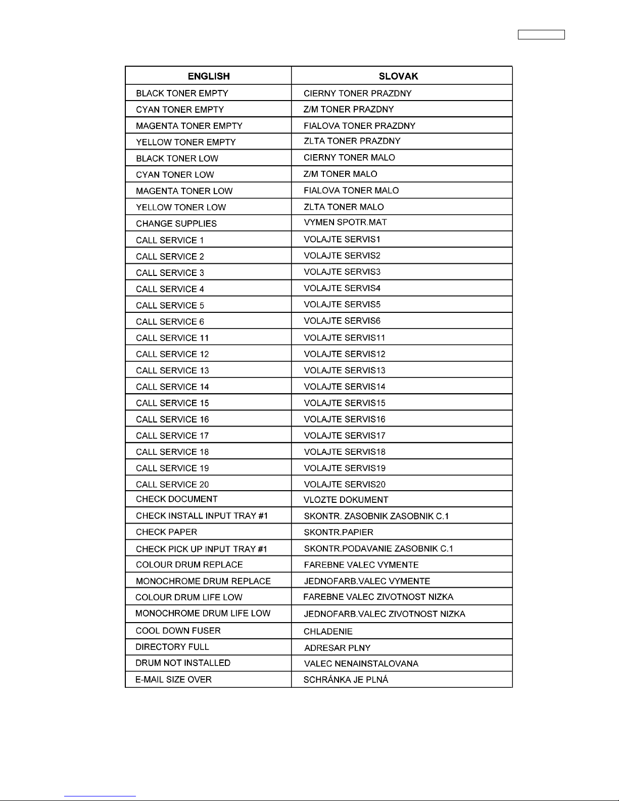
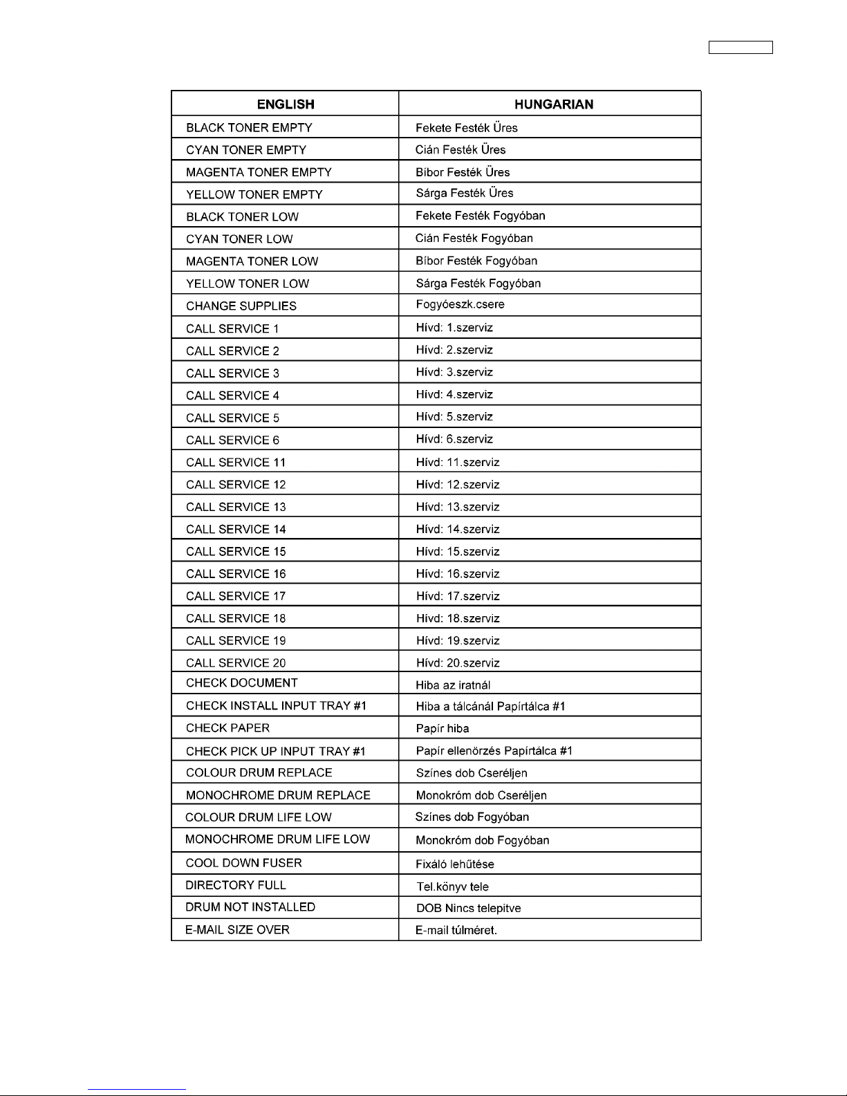
4.2.2. Error Message (Report)
4.2.2.1. CZECH
4.2.2.2. SLOVAK
4.2.2.3. HUNGARIAN

11
KX-MC6020HX
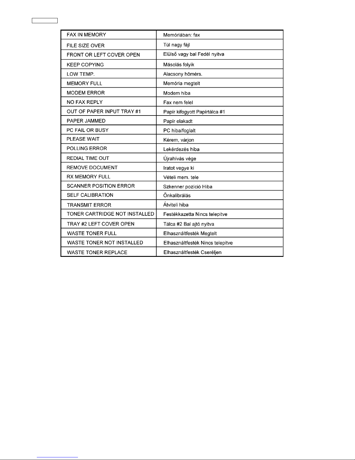
4.2.3. Error Message (Display)
4.2.3.1. CZECH

12
KX-MC6020HX
13
KX-MC6020HX
4.2.3.2. SLOVAK

14
KX-MC6020HX
15
KX-MC6020HX
4.2.3.3. HUNGARIAN
16
KX-MC6020HX

17
KX-MC6020HX
4.3. Precautions for Shipping
KX-MC6000 series have structural possibility that the waste toner may leak due to the vibration or the condition of the shipping.
Therefore, appropriate preventive measures for toner leaking should be taken for each service type. Precautions for each service
type are mentioned below.
4.3.1. Necessary Items and Procedures for Each Service Type

18
KX-MC6020HX
Case 1) Exchange Service
This service sends the replacement unit to customers first. Then the broken unit is sent to the service center.
1. Install dummy cartridges, which are used for toner leak prevention, before shipping the replacement units.
• This prevents leaking of the waste toner from the accumulator unit.
2. Request customers that install dummy cartridges, preliminarily installed in the replacement unit, to the broken unit and send it
to the service center.
3. Request customers to reinstall currently used toners and drums to the replacement unit.
Caution:
If the broken unit is shipped without dummy cartridges, the waste toner leaks into the inside of the units as shown below so that
it becomes unrepairable.
*Dummy cartridges are provided as Service parts. (P/N: PNZE2MC6020M) (Refer to FIXTURES AND TOOLS (P.485).)

19
KX-MC6020HX
Case 2) Regular Service
1. Request customers that send the broken unit with consumable supplies.
2. Response of service center after completing repairs
• Remove all toners and drums and repack the repaired
unit to ship. (Refer to Repack Procedure (P.20))
• Shipping Kit is provided as service parts (P/N:
PNZE1MC6020M). (Refer to FIXTURES AND TOOLS
(P.485).)
Case 3) On site Service
The unit is not shipped to anywhere so that no need to take toner leaking precautions.
20
KX-MC6020HX
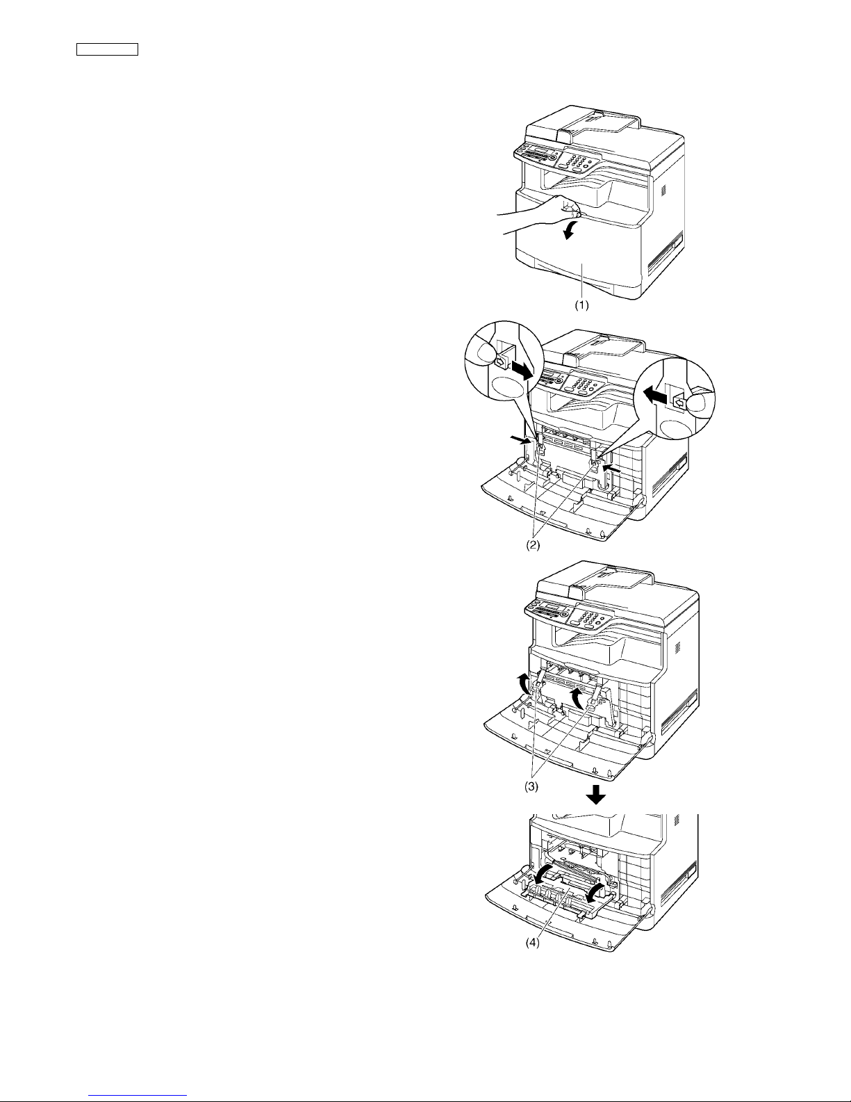
4.3.2. Repack Procedure
1.
Open the front cover (1) by holding the center part.
2.
Unlock the drum cartridge cover by pushing the tabs (2) in the direction
of the arrows.
3.
Lift up the levers (3) and open the drum cartridge cover (4).
21
KX-MC6020HX
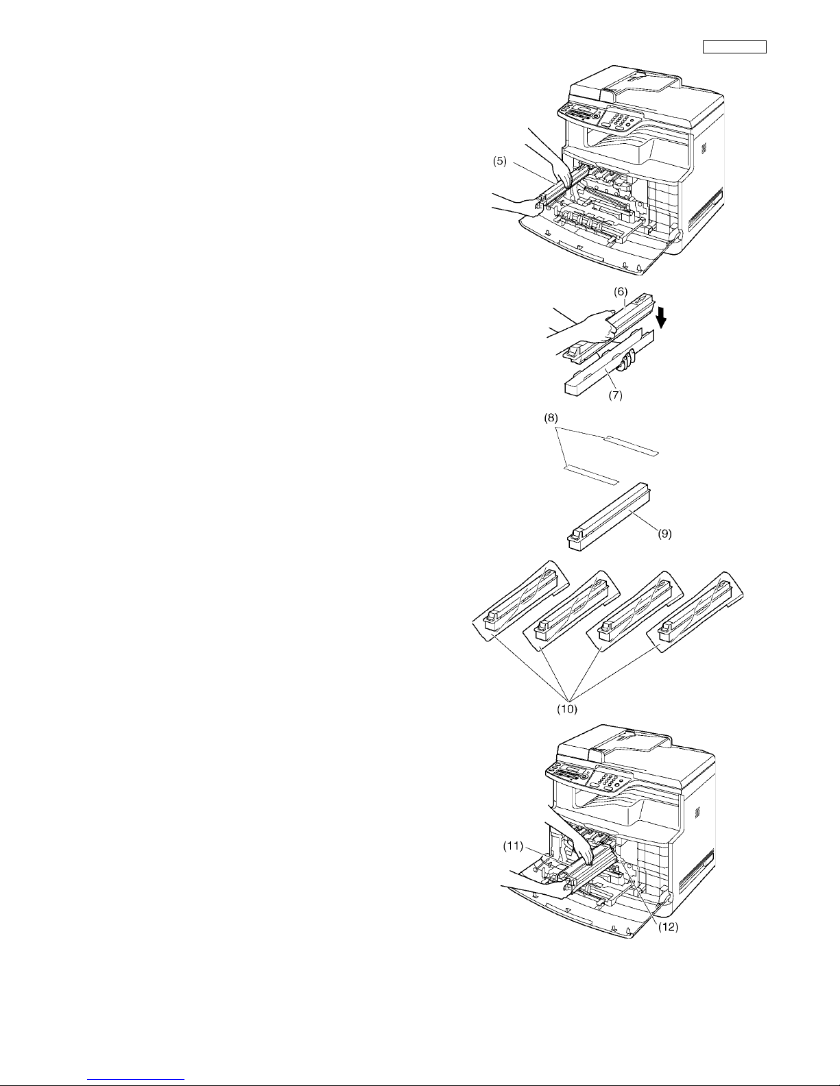
4.
Remove each toner cartridge (5) from the main unit. From left to right,
yellow, magenta, cyan, black.
• Do not touch the toner cartridge shutter at the bottom of the toner
cartridge. The toner may spill out of the toner cartridge.
5.
Put each toner cartridge (6) into protective tray (7).
6.
Apply shipping tapes (8) to each toner cartridge (9).
7.
Put the 4 toner cartridges into the protection bags (10).
8.
Remove the monochrome drum cartridge (11) from the main unit.
• Do not touch or scratch the accumulator unit (12).

22
KX-MC6020HX
9.
Firmly grip the monochrome drum cartridge (13) and insert the protective tray (14) by sliding it toward you.
• Do not touch or scratch the green drum surface (15) at the bottom
of the drum cartridge.
10.
Put the protective cover (16).
11.
Apply shipping tapes (17) to the monochrome drum cartridge (18).
12.
Put the monochrome drum cartridge into the protection bag (19).
13.
Hold and pull the front part of the color drum cartridge (20) using your
right hand to remove it from the main unit, then hold the green lever
(21) of the color drum cartridge using your left hand to support removing.
• Do not touch or scratch the accumulator unit (22).

23
KX-MC6020HX
14.
Firmly grip the color drum cartridge (23) and insert protective tray (24)
by sliding it toward you.
• Do not touch or scratch the green drum surface (25) at the bottom
of the drum cartridge.
15.
Put the protective cover (26).
16.
Apply shipping tapes (27) to color drum cartridge (28).
17.
Put the color drum cartridge into the protection bag (29).

24
KX-MC6020HX
Caution;
18.
Put the orange protector (30) to the main unit.

25
KX-MC6020HX
Installing Orange protector
26
KX-MC6020HX
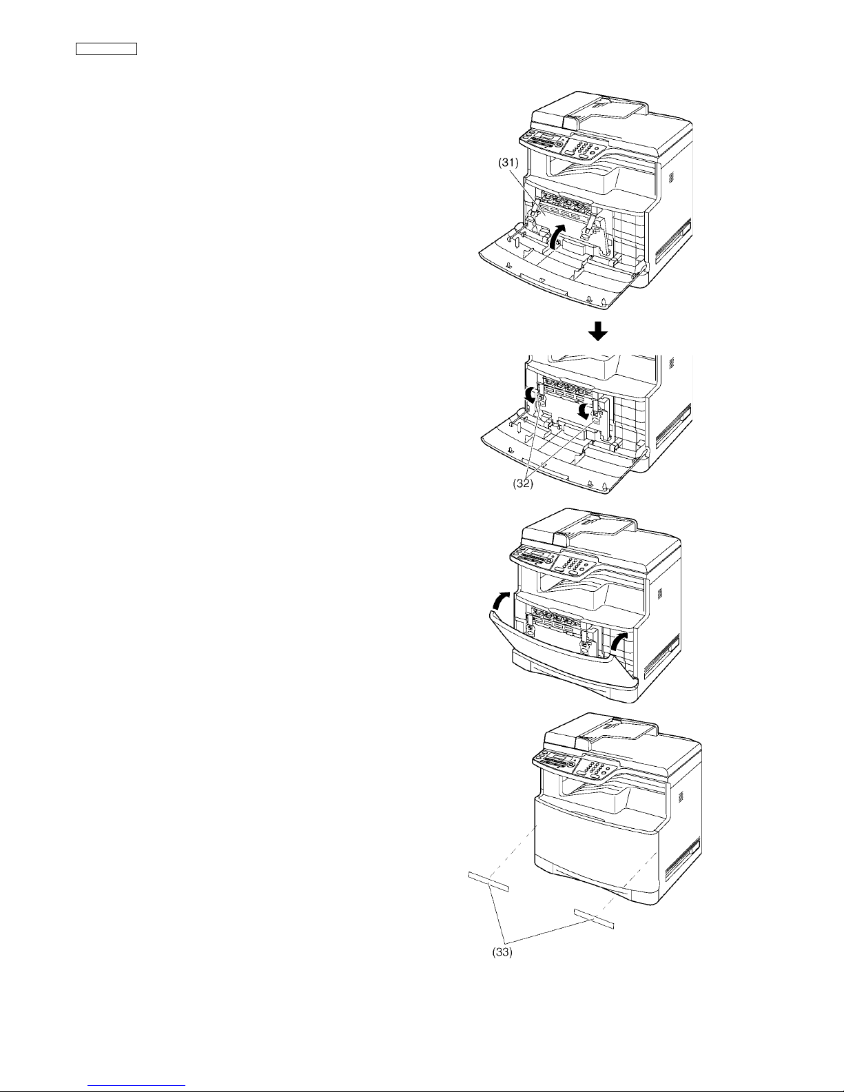
19.
Lift the drum cartridge cover (31) and push down on the levers (32) to
close.
• Push the levers down until you hear a click to ensure that the cover
is locked.
20.
Close the front cover.
21.
Apply shipping tapes (33) to the main unit.
27
KX-MC6020HX
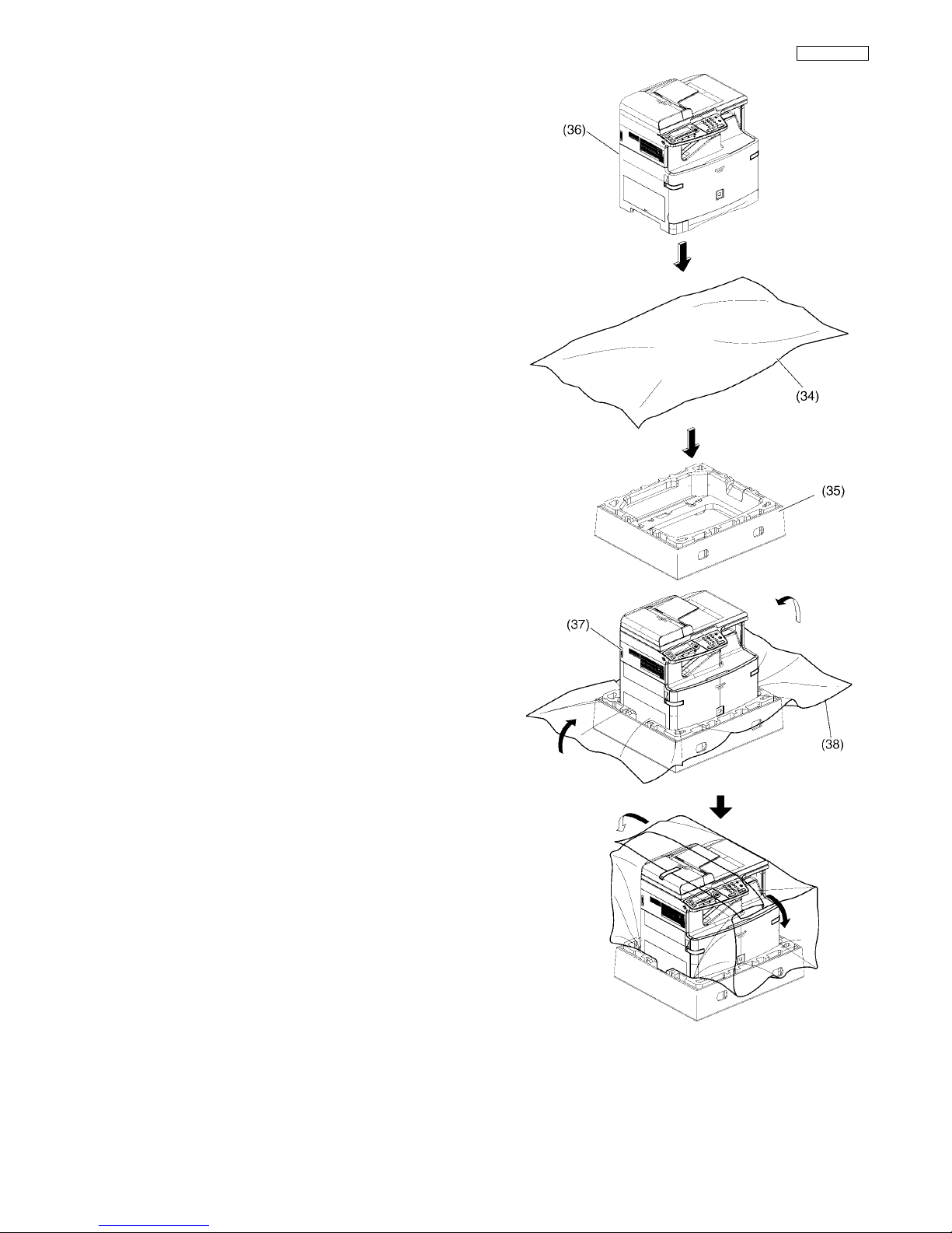
22.
Put the packing sheet (34) on the lower packing case (35). Then put
the main unit (36) on them.
23.
Wrap the main unit (37) by the packing sheet (38).
28
KX-MC6020HX
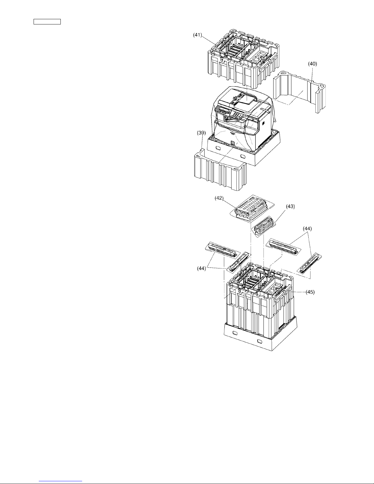
24.
Put the protection cover (39), (40) and (41).
25.
Pack the color drum cartridge (42), the monochrome drum cartridge
(43) and 4 toner cartridges (44) into the upper protection cover (45).

29
KX-MC6020HX
26.
Pack the pad (46) and the accessory box (47) into the upper protection
cover (48). Then put the upper packing cover (49).
27.
Put 4 joints (50) into the packing case (51).

30
KX-MC6020HX
5Features
5.1. General Features
General
• Help function
Display:
1. FEATURE LIST
2. DIRECTORY
3. FAX RECEIVING
4. CALLER ID
• LCD (Liquid Crystal Display) readout
Plain Paper Facsimile Machine
Recording paper exit (approx. 100 sheets)
Letter/A4/Legal, G3 compatible
Automatic document feeder (Up to 50 sheets)
Quick scan
Resolution: Standard/Fine/Super fine/Photo (64 level).
STANDARD: For normal-sized characters.
FINE: For small-sized characters.
SUPER FINE: For very small-sized characters.
PHOTO: For photographs, shaded drawings, etc.
Broadcast
• 250-sheet paper capacity (75 g/m
2
)
Distinctive ring detection.
Large Memory... Performed by DRAM
Approx. 150 pages of memory transmission
Approx. 630 pages of memory reception (max. 255 pages per
one reception.)
Enhanced Copier Function
Multi-copy function (up to 99 copies)
Enlargement and reduction
64-Level halftone
5.2. Hardware Requirements for Multi-Function Software
To use Multi-Function Station on your computer, the following are required:
Operating System:
Windows 98 / Windows Me / Windows 2000 / Windows XP / Windows Vista
CPU:
Windows 98/Windows Me/Windows 2000: Pentium
®
or higher processor
Windows XP: Pentium or higher processor
Windows Vista: Pentium 4 or higher processor
RAM:
Windows 98/Windows Me: 64 MB (128 MB or more recommended)
Windows 2000/Windows XP: 128 MB (256 MB or more recommended)
Windows Vista: 512 MB (1024 MB or more recommended)
Other Hardware:
CD-ROM drive
Hard disk drive with at least 150 MB of available space
USB interface
LAN interface (10Base-T / 100Base-TX)
Other:
Internet Explorer
®
5.0 or later
Warning;
• To assure continued emission limit compliance;
- use only shielded USB cable (Example: Hi-Speed USB 2.0 certified cable).
- use only shielded LAN cable (category 5 straight cable).
• To protect the unit, use only shielded USB cable in areas where thunderstorms occur.
 Loading...