

Page 1
Before attempting to connect or operate this product,
please read these instructions carefully and save this manual for future use.
The model number is abbreviated in some descriptions in this manual.
Operating Instructions
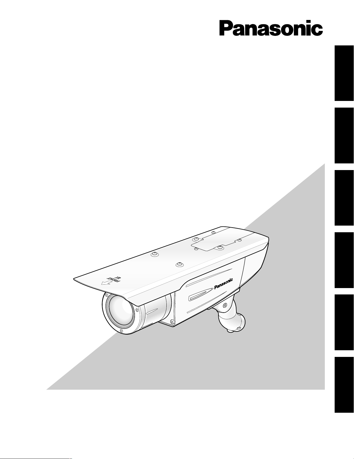
Color CCTV Cameras
Model Nos. WV-CW384E
WV-CW380/G
WV-CW384 is shown above.
FRANÇAIS DEUTSCH ENGLISHESPAÑOLITALIANOкмллдав
384
-CW
V
W
Page 2
2
ENGLISH VERSION
CAUTION:
An ALL-POLE MAINS SWITCH with a contact separation of at
least 3 mm in each pole shall be incorporated in the electrical
installation of the building.
The lightning flash with arrowhead symbol,
within an equilateral triangle, is intended to
alert the user to the presence of uninsulated
"dangerous voltage" within the product's
enclosure that may be of sufficient magnitude to constitute a risk of electric shock to
persons.
CAUTION: TO REDUCE THE RISK OF ELECTRIC SHOCK,
DO NOT REMOVE COVER (OR BACK).
NO USER-SERVICEABLE PARTS INSIDE.
REFER SERVICING TO QUALIFIED SERVICE PERSONNEL.
CAUTION
RISK OF ELECTRIC SHOCK
DO NOT OPEN
CAUTION:
Before attempting to connect or operate this product, please
read the label on the bottom.
The exclamation point within an equilateral
triangle is intended to alert the user to the
presence of important operating and maintenance (servicing) instructions in the literature accompanying the appliance.
WARNING:
• This apparatus must be earthed.
• All work related to the installation of this product should be made
by qualified service personnel or system installers.
• The connections should comply with local electrical code.
We declare under our sole responsibility that the product to which this
declaration relates is in conformity with the standards or other normative
documents following the provisions of Directives 2006/95/EC and
2004/108/EC.
Wij verklaren als enige aansprakelijke, dat het product waarop deze
verklaring betrekking heeft, voldoet aan de volgende normen of andere
normatieve documenten, overeenkomstig de bepalingen van Richtlijnen
2006/95/EC en 2004/108/EC.
Vi erklærer os eneansvarlige for, at dette produkt, som denne
deklaration omhandler, er i overensstemmelse med standarder eller
andre normative dokumenter i følge bestemmelserne i direktivene
2006/95/EC og 2004/108/EC.
Vi deklarerar härmed värt fulla ansvar för att den produkt till vilken
denna deklaration hänvisar är i överensstämmelse med
standarddokument, eller andra normativa dokument som framställs i
direktiv nr. 2006/95/EC och 2004/108/EC.
Ilmoitamme yksinomaisella vastuullamme, että tuote, jota tämä ilmoitus
koskee, noudattaa seuraavia standardeja tai muita ohjeellisia asiakirjoja,
jotka noudattavat direktiivien 2006/95/EC ja 2004/108/EC säädöksiä.
Vi erklærer oss alene ansvarlige for at produktet som denne erklæringen
gjelder for, er i overensstemmelse med følgende normer eller andre
normgivende dokumenter som følger bestemmelsene i direktivene
2006/95/EC og 2004/108/EC.
FOR YOUR SAFETY PLEASE READ THE FOLLOWING TEXT CAREFULLY.
WARNING: This apparatus must be earthed.
IMPORTANT
The wires in this mains lead are coloured in accordance with the following code.
Green-and-yellow: Earth
Blue: Neutral
Brown: Live
As the colours of the wire in the mains lead of this appliance may
not correspond with the coloured markings identifying the terminals in
your plug, proceed as follows.
The wire which is coloured green-and-yellow must be connected to
the terminal in the plug which is marked with the letter E or by the earth
symbol
I or coloured green or green-and-yellow.
The wire which is coloured blue must be connected to the terminal
in the plug which is marked with the letter N or coloured black.
The wire which is coloured brown must be connected to the terminal in the plug which is marked with the letter L or coloured red.
For U.K.
Turn the power off at the mains to disconnect the main power
for all unit.
Page 3

3
Important Safety Instructions ...........................................................................................................................................................4
Limitation of Liability ........................................................................................................................................................................5
Disclaimer of Warranty ....................................................................................................................................................................5
Preface ............................................................................................................................................................................................6
Features ..........................................................................................................................................................................................6
Precautions ......................................................................................................................................................................................7
Major Operating Controls and Their Functions ................................................................................................................................8
Precautions for Installation ..............................................................................................................................................................9
Installations/Connections ...............................................................................................................................................................10
■ Preparations .........................................................................................................................................................................10
■ Camera installation ...............................................................................................................................................................10
About Setup Menus .......................................................................................................................................................................21
■ Basic operation .....................................................................................................................................................................22
Setting Procedures ........................................................................................................................................................................23
Language Setup (LANGUAGE SETUP) ....................................................................................................................................23
1. Camera Identification Setting (CAMERA ID) .......................................................................................................................23
2. Light Control Mode Setting (ALC) ........................................................................................................................................24
3. Shutter Speed Setting (SHUTTER) ......................................................................................................................................25
4. Gain Control Setting (AGC) ..................................................................................................................................................26
5. Electronic Sensitivity Enhancement (SENS UP) ..................................................................................................................26
6. Synchronization Setting (SYNC) ..........................................................................................................................................26
7. White Balance Setting (WHITE BAL) ...................................................................................................................................27
8. Motion Detection Setting (MOTION DET) ............................................................................................................................27
9. Digital Noise Reduction Setting (DNR) .................................................................................................................................29
10. Resolution Setting (RESOLUTION) .....................................................................................................................................29
11. Black and White Mode Setting (BW MODE) ........................................................................................................................29
12. Privacy Zone Setting (PRIVACY ZONE) ..............................................................................................................................30
13. Electronic Zoom (EL-ZOOM) ................................................................................................................................................30
14. Auto Image Stabilizer (STABILIZER) ...................................................................................................................................31
15. LED Setting (LED) ................................................................................................................................................................31
16. Back-focus Setting (BACK-FOCUS SETUP) .......................................................................................................................31
17. Special Menu (SPECIAL SETUP) ........................................................................................................................................32
Troubleshooting .............................................................................................................................................................................34
Specifications ................................................................................................................................................................................35
Standard Accessories ....................................................................................................................................................................36
CONTENTS
ENGLISH
Page 4

4
Important Safety Instructions
1) Read these instructions.
2) Keep these instructions.
3) Heed all warnings.
4) Follow all instructions.
5) Clean only with dry cloth.
6) Do not block any ventilation openings. Install in accordance with the manufacturer's instructions.
7) Do not install near any heat sources such as radiators, heat registers, stoves, or other apparatus (including amplifiers) that
produce heat.
8) Do not defeat the safety purpose of the polarized or grounding-type plug. A polarized plug has two blades with one wider
than the other. A grounding type plug has two blades and a third grounding prong. The wide blade or the third prong are
provided for your safety. If the provided plug does not fit into your outlet, consult an electrician for replacement of the
obsolete outlet.
9) Protect the power cord from being walked on or pinched particularly at plugs, convenience receptacles, and the point
where they exit from the apparatus.
10) Only use attachments/accessories specified by the manufacturer.
11) Use only with the cart, stand, tripod, bracket, or table specified by the manufacturer, or sold with the apparatus. When a
cart is used, use caution when moving the cart/apparatus combination to avoid injury from tip-over.
12) Unplug this apparatus during lightning storms or when unused for long periods of time.
S3125A
Page 5

5
Limitation of Liability
THIS PUBLICATION IS PROVIDED "AS IS" WITHOUT WARRANTY OF ANY KIND, EITHER EXPRESS OR IMPLIED,
INCLUDING BUT NOT LIMITED TO, THE IMPLIED WARRANTIES OF MERCHANTABILITY, FITNESS FOR ANY PARTICULAR PURPOSE, OR NON-INFRINGEMENT OF THE
THIRD PARTY'S RIGHT.
THIS PUBLICATION COULD INCLUDE TECHNICAL INACCURACIES OR TYPOGRAPHICAL ERRORS.
CHANGES ARE ADDED TO THE INFORMATION HEREIN,
AT ANY TIME, FOR THE IMPROVEMENTS OF THIS PUBLICATION AND/OR THE CORRESPONDING PRODUCT (S).
Disclaimer of Warranty
IN NO EVENT SHALL Panasonic Corporation BE LIABLE
TO ANY PARTY OR ANY PERSON, EXCEPT FOR
REPLACEMENT OR REASONABLE MAINTENANCE OF
THE PRODUCT, FOR THE CASES, INCLUDING BUT NOT
LIMITED TO BELOW:
(1) ANY DAMAGE AND LOSS, INCLUDING WITHOUT LIM-
ITATION, DIRECT OR INDIRECT, SPECIAL, CONSEQUENTIAL OR EXEMPLARY, ARISING OUT OF OR
RELATING TO THE PRODUCT;
(2) PERSONAL INJURY OR ANY DAMAGE CAUSED BY
INAPPROPRIATE USE OR NEGLIGENT OPERATION
OF THE USER;
(3) UNAUTHORIZED DISASSEMBLE, REPAIR OR MODIFI-
CATION OF THE PRODUCT BY THE USER;
(4) INCONVENIENCE OR ANY LOSS ARISING WHEN
IMAGES ARE NOT DISPLAYED, DUE TO ANY REASON
OR CAUSE INCLUDING ANY FAILURE OR PROBLEM
OF THE PRODUCT;
(5) ANY PROBLEM, CONSEQUENTIAL INCONVENIENCE,
OR LOSS OR DAMAGE, ARISING OUT OF THE SYSTEM COMBINED BY THE DEVICES OF THIRD PARTY;
(6) ANY CLAIM OR ACTION FOR DAMAGES, BROUGHT
BY ANY PERSON OR ORGANIZATION BEING A PHOTOGENIC SUBJECT, DUE TO VIOLATION OF PRIVACY
WITH THE RESULT OF THAT SURVEILLANCE-CAMERA'S PICTURE, INCLUDING SAVED DATA, FOR SOME
REASON, BECOMES PUBLIC OR IS USED FOR THE
PURPOSE OTHER THAN SURVEILLANCE.
Page 6

6
Preface
Panasonic's WV-CW384 and WV-CW380 cameras introduce high picture quality by use of Super-Dynamic 1/3-inch type {1/3"}
CCD and digital signal processing LSIs. These cameras are designed for installation on the wall or the ceilling, using the supplied camera mount bracket.
Features
Introduction of SUPER-D3 (super dynamic function)
Integration of SUPER-D3 into the CCD and signal processing circuit has achieved approximately 160 times higher dynamic
range as compared with conventional camera. Therefore, a photographic subject on which much illuminance difference exists
resulting from bright and dark areas can be naturally displayed in an image.
Auto back focus function (ABF) equipped
The back focus adjustment can be performed through the operation buttons on this unit and the setup menu.
The back focus can be remotely adjusted through the system controller (option) even after installation of this unit. The auto
back focus function also allows users to correct out of focus when changing between color and black-and-white images.
High sensitivity achieved thanks to noise reduction function
The introduction of low noise circuit design has achieved excellently high sensitivity resulting in the minimum illuminance of
0.65 lx in the color mode and 0.09 lx in the black-and-white mode.
Night monochrome image activation function equipped
No operation is required at night because the image automatically changes from the color mode to the black-and-white mode
at low illuminance.
Motion detector function equipped
If motion is observed in the monitor, the camera is covered with a cloth, a cap, or the like, or the camera direction is changed
during monitoring, an alarm signal is provided.
Page 7
7
This product has no power switch.
Power is supplied from an external 12 V DC/24 V AC (WVCW384) or 220 V to 240 V AC (WV-CW380) power-supply
device. Refer to service personnel for how to turn on/off the
power.
To keep on using with stable performance
• Parts of this product may deteriorate and it may shorten
lifetime of the product when using in locations subject
to high temperatures and high humidity.
Do not expose the product to direct heat such from a
heater.
• Use this product at temperature within –30 °C to
+50 °C* and humidity below 90 %.
* –10 °C to +50 °C at 12 V DC
Do not drop metallic parts through slots.
This could permanently damage this product. Turn the
power off immediately and contact qualified service personnel for service.
Do not rub the edges of metal parts with your hand.
Failure to observe this may cause injury.
Do not attempt to disassemble this product.
To prevent electric shock, do not remove screws or covers.
There are no user-serviceable parts inside.
Ask qualified service personnel for servicing.
Handle this product with care.
Do not abuse this product. Avoid striking, shaking, etc.
The product could be damaged by improper handling or
storage.
Cleaning this product body
Turn the power off when cleaning the product. Use a dry
cloth to clean the product. Do not use strong abrasive
detergent when cleaning the product body. When the dirt is
hard to remove, use a mild detergent and wipe gently.
Then, wipe off the remaining detergent with a dry cloth.
Otherwise, it may cause discoloration. When using a chemical cloth for cleaning, read the caution provided with the
chemical cloth product.
Clean the lens with care.
Do not clean the lens with strong or abrasive detergents.
Use lens tissue or a cotton tipped applicator and ethanol.
Discoloration on the CCD color filter
When continuously shooting a bright light source such as a
spotlight, the color filter of the CCD may have deteriorated
and it may cause discoloration.
Even when changing the fixed shooting direction after continuously shooting a spotlight for a certain period, the discoloration may remain.
Precautions
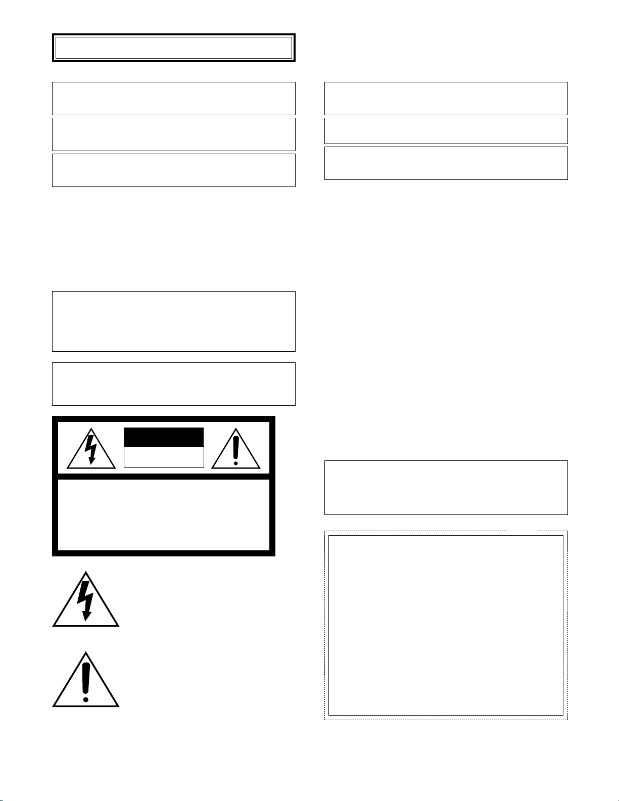
Do not aim this product at strong light sources.
A light source such as a spot light causes a blooming (light
bleeding) or a smear (vertical lines).
About the dehumidifying device
• This product has dehumidifying device to keep the
inside at low moisture level, preventing condensation
and quickly dissipating dew if produced.
• Dew may be produced depending on the conditions of
temperature, humidity, winds, and rain, and it may take
time to dehumidify.
• Never seal the surfaces of the dehumidifying device.
Turn the circuit breaker off which supplies this product
with the power when abnormal conditions are encountered.
Do not operate this product beyond the specified temperature, humidity or power source ratings.
Use this product at temperature within –30 °C to +50 °C*
and humidity below 90 %. The input power source is 12 V
DC/24 V AC (WV-CW384) or 220 V to 240 V AC (WVCW380).
* –10 °C to +50 °C at 12 V DC
Use at low temperatures
• To operate the camera at temperatures of –10 °C or
lower, it will take 30 minutes or more after turning on the
power to warm up the camera.
• Images may be disturbed because the built-in heater is
automatically toggled between ON and OFF resulting
from a change in usage environment.
What to do if OVER HEAT appears on the display.
This message indicates that the inside of this product has
become extremely hot. Immediately turn off the product
and contact your dealer.
Smear
Blooming
Dehumidifying device
Bright subject
Page 8
8
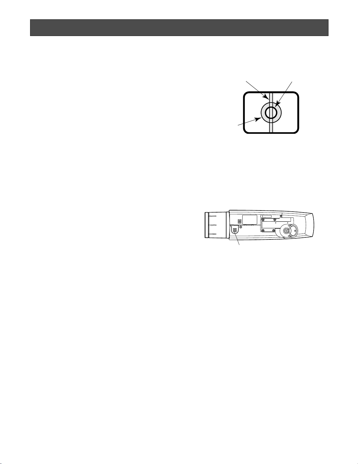
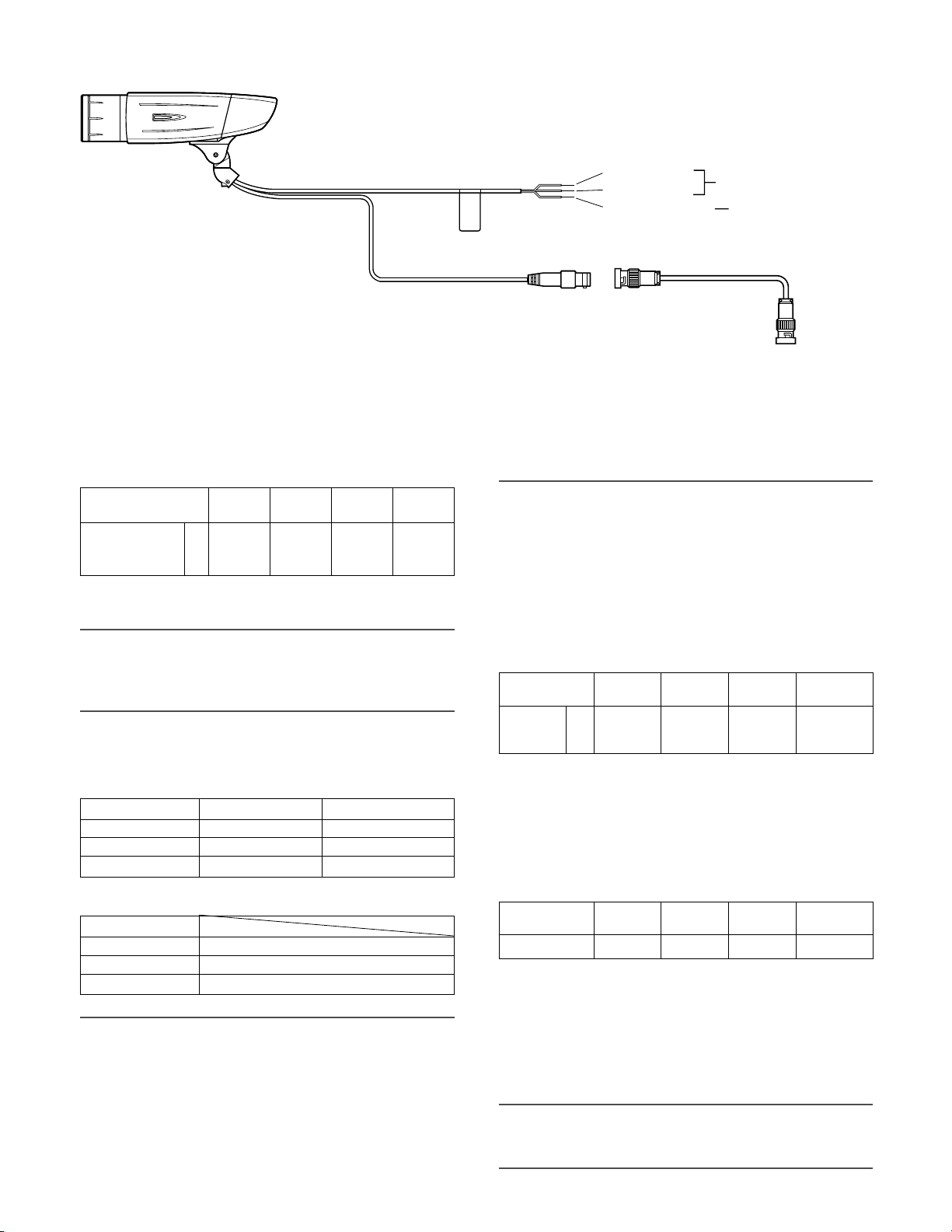
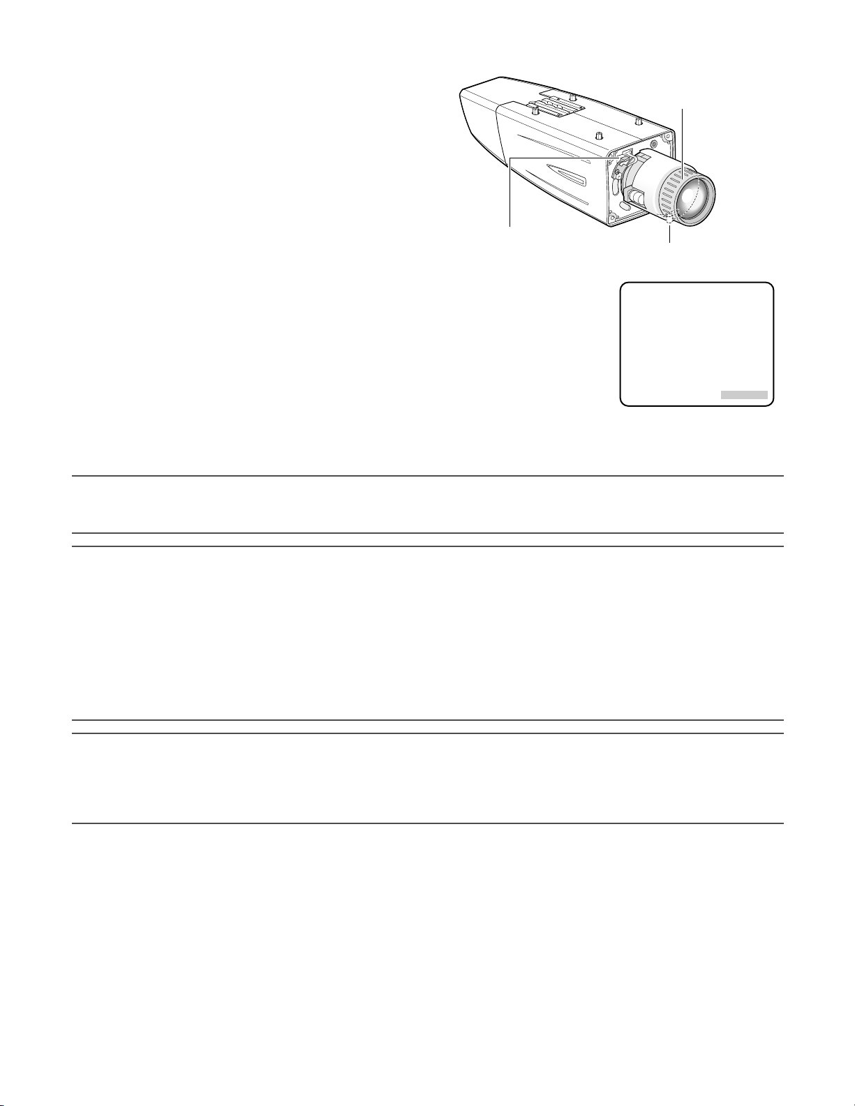
q Monitor output jack
(ø3.5 mm mini jack (monaural))
Connects to a monitor for adjustment to adjust the view
angle and focus.
w Zoom adjustment ring
Adjusts the zoom position. (☞ page 16)
e Auto back focus button
Activates the auto back focus function.
r Focus lock knob
Locks the focal point. (☞ page 16)
t Sunshield (accessory)
y Front glass
u Lens cover
Protects the lens. The lens cover is removed at lens
adjustment. After lens adjustment, the fixing screws
shall be securely tightened. (☞ page 15)
i LED
Lights, blinks, or goes off depending on settings. (☞
page 31)
o Tilting lock screw
Locks the tilt position. (☞ page 15)
!0 Panning lock screw
Locks the panning position. (☞ page 15)
!1 Power cord
Caution:
• This cord supplies 12 V DC/24 V AC (WV-CW384) or
220 V to 240 V AC (WV-CW380) from an external power
source.
!2 Video output cable
!3 Safety wire
!4 Rear cover
!5 Switch cover
This cover is removed at operating the operation buttons. After the button operation, the fixing screws shall
be securely tightened. (☞ page 17)
!6 - @0 Operation buttons
!6 Up button (UP)
!7 Right button (RIGHT)
!8 Down button (DOWN)
!9 Left button (LEFT)
@0 Set button (SET)
@1 Camera mount bracket (accessory)
@2 Adapter box (accessory)
Major Operating Controls and Their Functions
e
wq
!6
@0
!8
!9
!7
!5
t
y
u
i
o!0
!2
!3
!4
r
@2
@1
!1
Page 9

9
Installing place
Contact your dealer for assistance if you are unsure of an
appropriate place in your particular environment.
Make sure that the installation area is strong enough to hold
this product, such as a concrete ceiling. When the installation area is not strong enough, reinforce and strengthen it.
Avoid installing this product in the following locations.
• Locations where a chemical agent is used such as a
swimming pool
• Locations subject to steam and oil smoke such as a
kitchen
• Locations near flammable gas or vapor
• Locations where radiation or x-ray emissions are produced
• Locations subject to strong magnetic field or radio
waves
• Locations where corrosive gas is produced
• Locations where it may be damaged by briny air such
as seashores
• Locations where the temperature is not within –30 °C to
+50 °C*.
* –10 °C to +50 °C at 12 V DC
• Locations subject to vibrations (This product is not
designed for on-vehicle use.)
Be sure to remove this product if it is not in use.
White balance
White balance may be not adjusted appropriately in the following cases.
• When a subject is extremely less white or nearly single
colored
• When a subject is in the outdoors in the morning or
evening or in the low illuminance state
• When a subject is in the atmosphere of extremely different color temperature (e.g. under color illumination)
Keep the video output cable away from the lighting
cable.
Failure to observe this may cause noise.
Radio interference
When this product is used near TV/radio antenna, strong
electric field or magnetic field (near a motor or a transformer), images may be distorted and noise sound may be
produced. In such a case, run the camera cable through
specialized conduit tubes.
Mounting screws
Only the fixing screws are provided to fix this product with
the provided mount bracket. It is necessary to procure
screws or bolts to mount the product. Prepare them
according to the material and strength of the area where
the product is to be installed.
The screws and bolts must be tightened with an appropriate tightening torque according to the material and strength
of the installation area. After tightening the screws or bolts,
perform visual check to ensure tightening is enough and
there is no backlash.
Piping for cables
If this product is operated outdoors, be sure to install connecting tubes and run the cables through the tubes to protect the cables from being frozen or direct sunlight.
Precautions for Installation
Page 10
10
■ Preparations
The camera can be mounted either of the following ways.
• To mount the camera directly on the wall
• To mount the camera on the wall using a adapter box
Note:
• The screws that secure the camera mount bracket on a wall are not supplied. Prepare the screws according to the material, structure, strength
and other factors of the mounting area and the total weight of objects to
be mounted.
Important:
• Prepare the mounting screws according to the material of the area where the camera mount bracket is to be installed. In
this case, wood screws and nails should not be used. Recommended tightening torque M4: 1.6 N·m
• Required pull-out capacity of a single screw/bolt is 196 N or more.
• If a ceiling board such as plaster board is too weak to support the total weight, the area shall be sufficiently reinforced.
• When using the provided adapter box, make sure that the drain slits do not face upward.
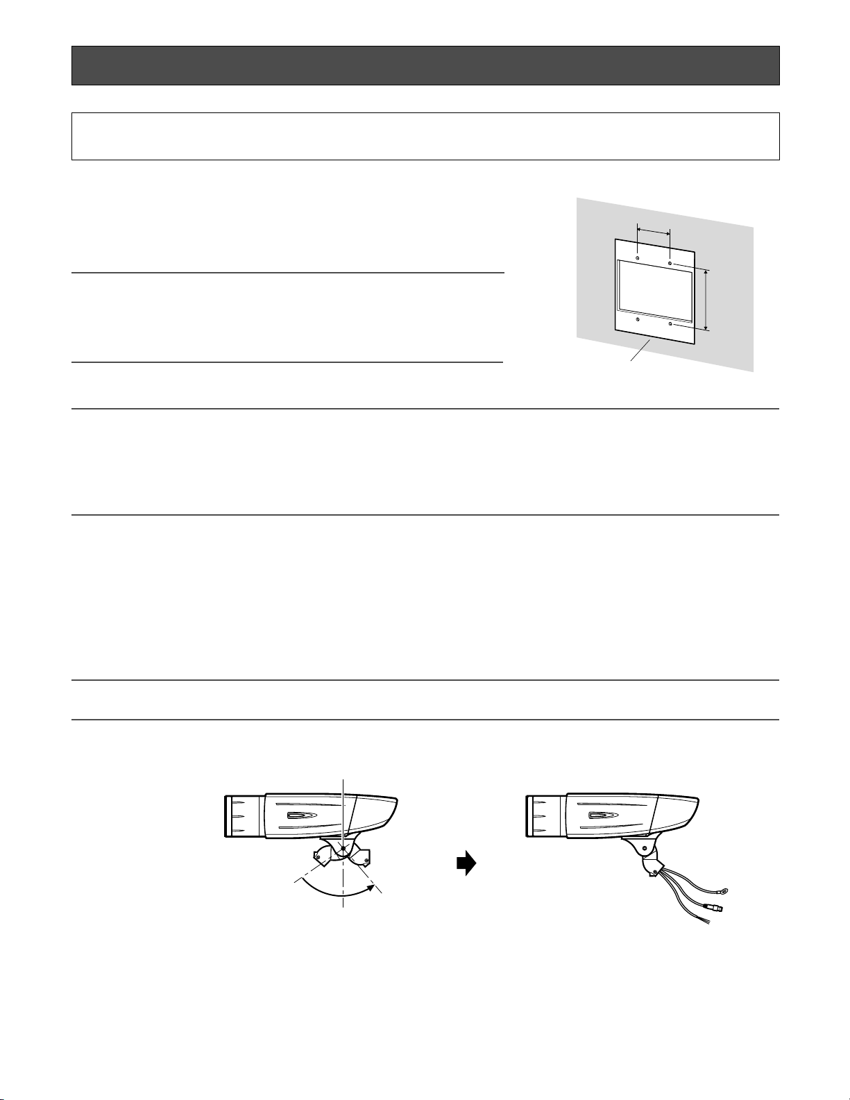
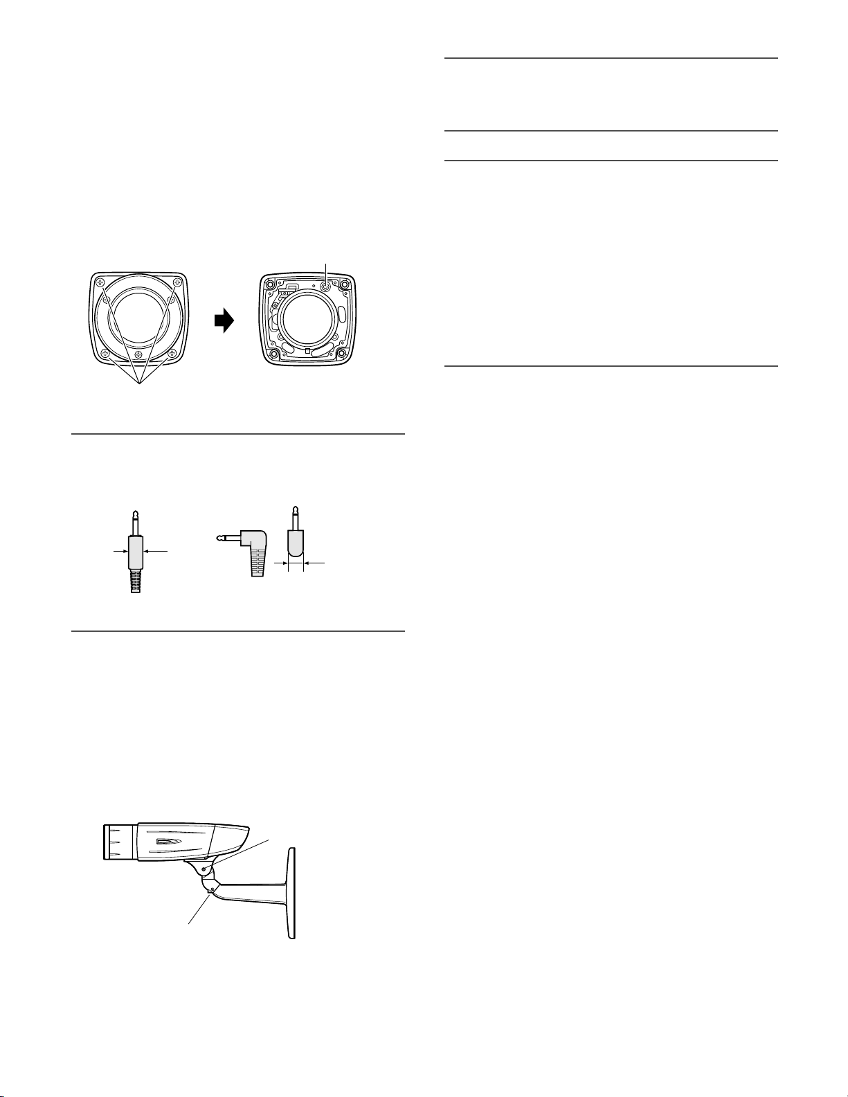
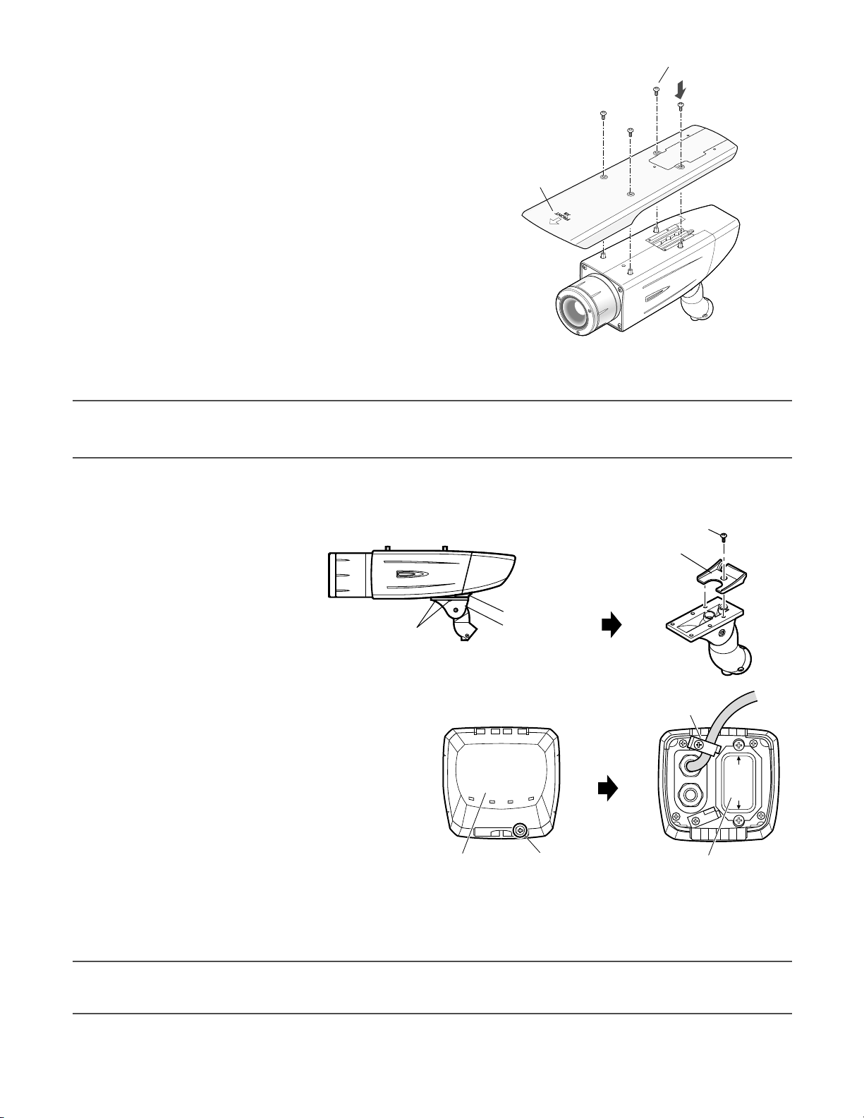
■ Camera installation
zSecure the camera to the camera mount bracket
The tilt angle is locked downward at shipment.
1. Loosen the tilting lock screw approx. 1 rotation and adjust the tilt angle of the camera to the horizontal position.
2. Tighten the tilting lock screw again after tilt angle adjustment.
Note:
• Use a hexagonal wrench with width across flats of 4 mm (locally procured) to loosen or tighten the tilting lock screw.
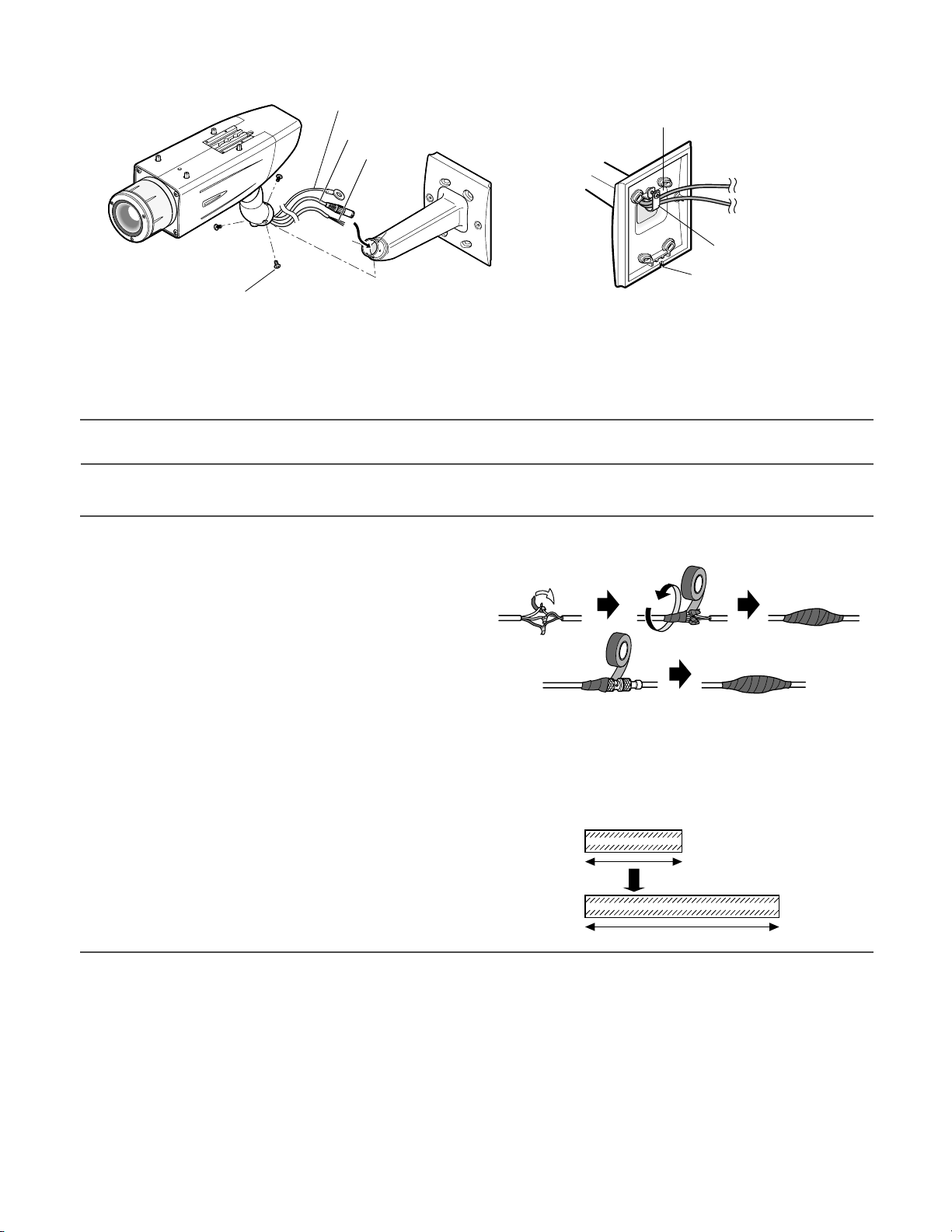
3. Pass the video output cable, power cord and safety wire through the camera mount bracket from the camera side to the
wall side and use the cable clamp to bundle the cables and wire.
Installations/Connections
Caution:
ONLY CONNECT THIS TO 24 V AC OR 12 V DC CLASS 2 POWER SUPPLY. (WV-CW384)
[Mounting position on the wall]
46 mm
83.5 mm
Junction box (locally procured)
Tilting lock screw
Camera main body
Approx. 90 °
Page 11
11
4. Secure the camera to the camera mount bracket with the 3 camera fixing screws (accessories).
5. Remove the screw from the mounting boss for safety wire of the camera mount bracket and secure the safety wire with the
screw.
Important:
• Ensure that the safety wire is firmly secured. Recommended tightening torque: 0.59 N·m
Important:
<Waterproof treatment>
• To install this product outdoors, be sure to
waterproof the cables. The camera main
body is waterproof, but the mount bracket
and adapter box are not waterproof.
• To install this product outdoors, use waterproof silicon rubber or the like to apply
waterproof treatment to the camera mount
bracket, adapter box, cable access hole,
screw holes, and screws.
• To install this product on a wall, face the drain slit of the camera mount bracket downward. Do not block the drain slit.
Do not waterproof the drain slit, either.
• Be sure to use the supplied waterproof tape at the connection parts of the power cord and video output cable to apply
waterproof treatment.
<How to wind the supplied waterproof tape>
• Stretch the tape by approx. twice (see the illustration at right) and
wind it around the cables. Insufficient tape stretch causes insufficient waterproofing.
• Wind the cable with tape in a half-overlapping manner.
Camera main body
Camera fixing screw x3 (M4 x 8) (accessories)
Safety wire
Video output cable
Power cord
Camera mount bracket
Mounting boss for safety wire
Video output cable
Power cord
Cable clamp
Drain slit
Camera mount bracket
Power cord
Video output cable
Stretch the tape to approx. twice.
Twice in length
Page 12
12
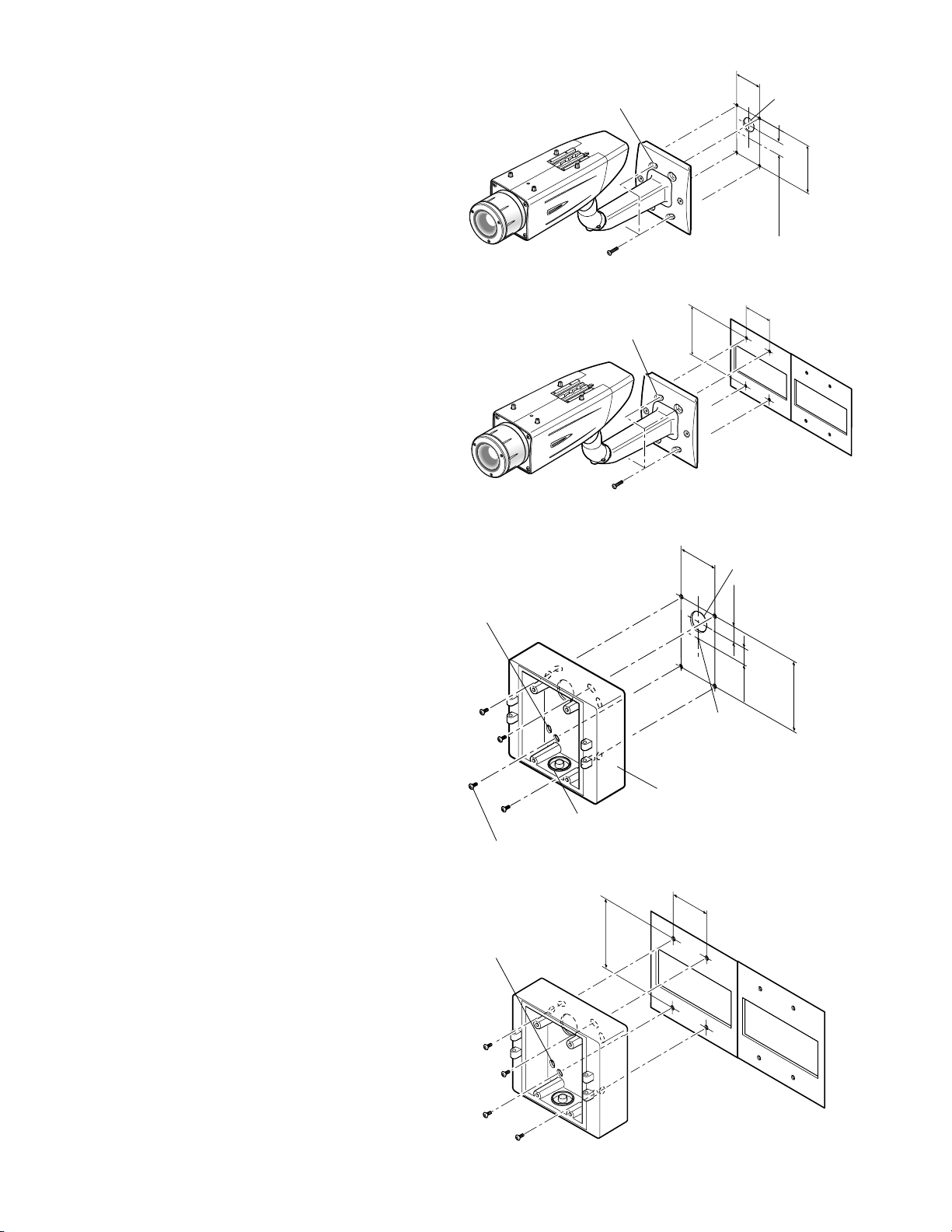
xSecure the camera mount bracket
• When the camera is directly installed on a wall
Use 4 screws (locally procured) to secure the camera
mount bracket to a wall or a junction box (locally procured).
If a junction box is used, putting the boxes side by side
is recommended as shown in the illustration at right. (for
easy cable passing)
• When the camera is installed on a wall using the
adapter box
1. Use 4 screws (locally procured) to secure the adapter
box to a wall or a junction box (locally procured).
• If a junction box is used, putting the boxes side by side
is recommended as shown in the illustration at right.
(for easy cable passing)
6 mm (W) x 10 mm (L)
(long hole)
Camera mount bracket
Mounting screw x4 (locally procured)
46 mm
Cable access hole
83.5 mm
22 mm
6 mm (W) x 10 mm (L)
(long hole)
Mounting screw x4 (locally procured)
Hole 6 mm (W) x 10 mm (H)
46 mm
83.5 mm
Camera mount bracket
46 mm
Cable access hole
24.5 mm
22 mm
Center of
adapter box
Junction boxes
83.5 mm
Cable access hole (used for wiring)
(G3/4" internal thread)
Mounting screw x4
(locally procured)
Hole
6 mm (W) x 10 mm (H)
Mounting screw x4
(locally procured)
Adapter box
46 mm
83.5 mm
Junction boxes
Page 13
13
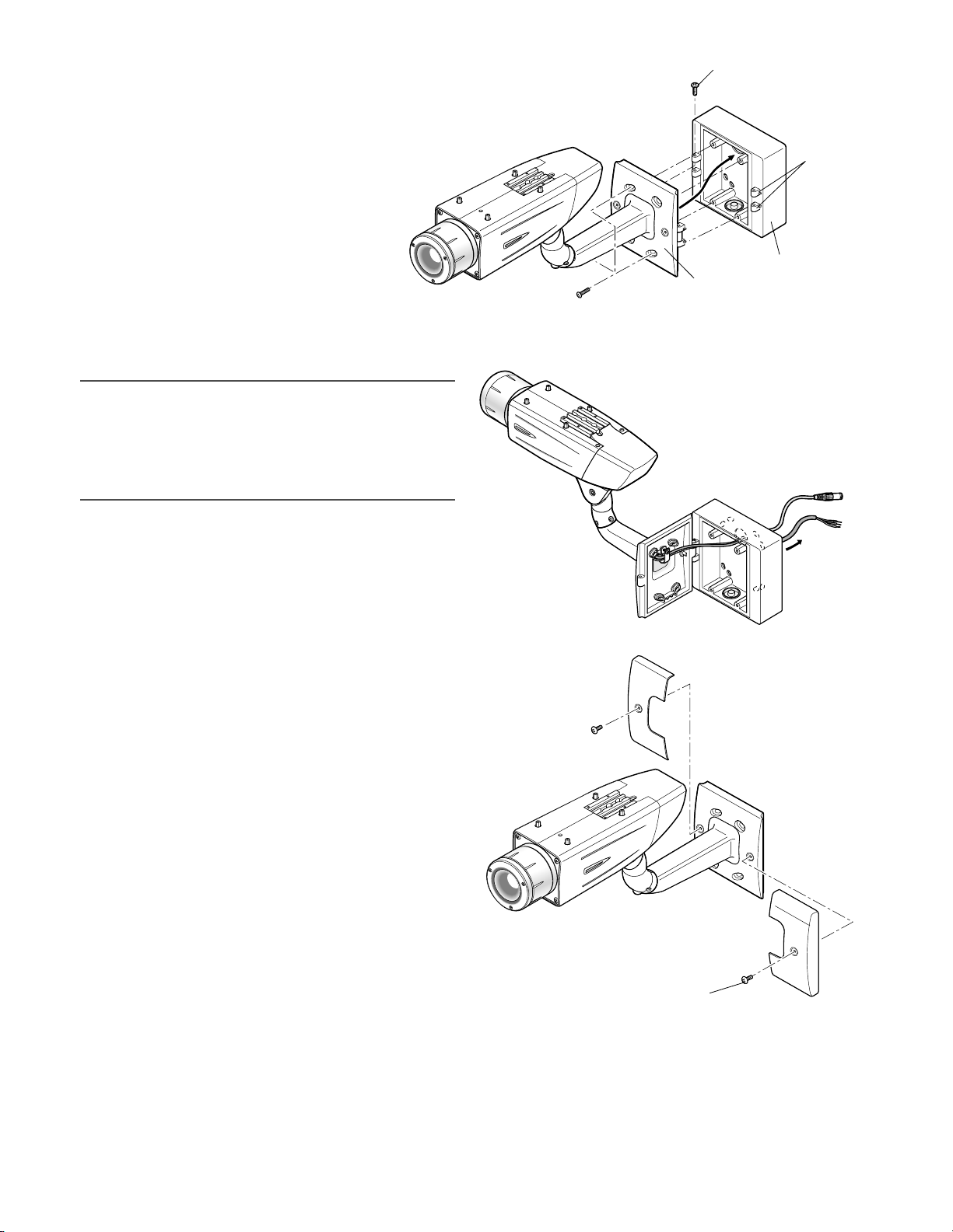
2. Attach the camera mount bracket to the left
or right hinges of adapter box.
cSecure the mount bracket covers to the
camera mount bracket with the 2 mount
bracket cover screws (accessories).
Note:
• The right or left hinges of the adapter box shall be
selected so as to prevent the motion of the camera
mount bracket from being interfered with by obstructions such as a wall when the camera mount bracket is
connected to the hinges of the adapter box.
Adaptor box mounting screw (M4 x 35)
Hinges
Adapter box
Mount bracket
Mounting screw for adapter box/
camera mount bracket x4 (M5 x 20)
Mount bracket cover x2
Mount bracket cover screw x2
(M3 x 6) (accessories)
Camera mount
bracket
Page 14
<WV-CW380>
Wire Color
Brown 220 V to 240 V AC (L)
Blue 220 V to 240 V AC (N)
Green/Yellow To GND
14
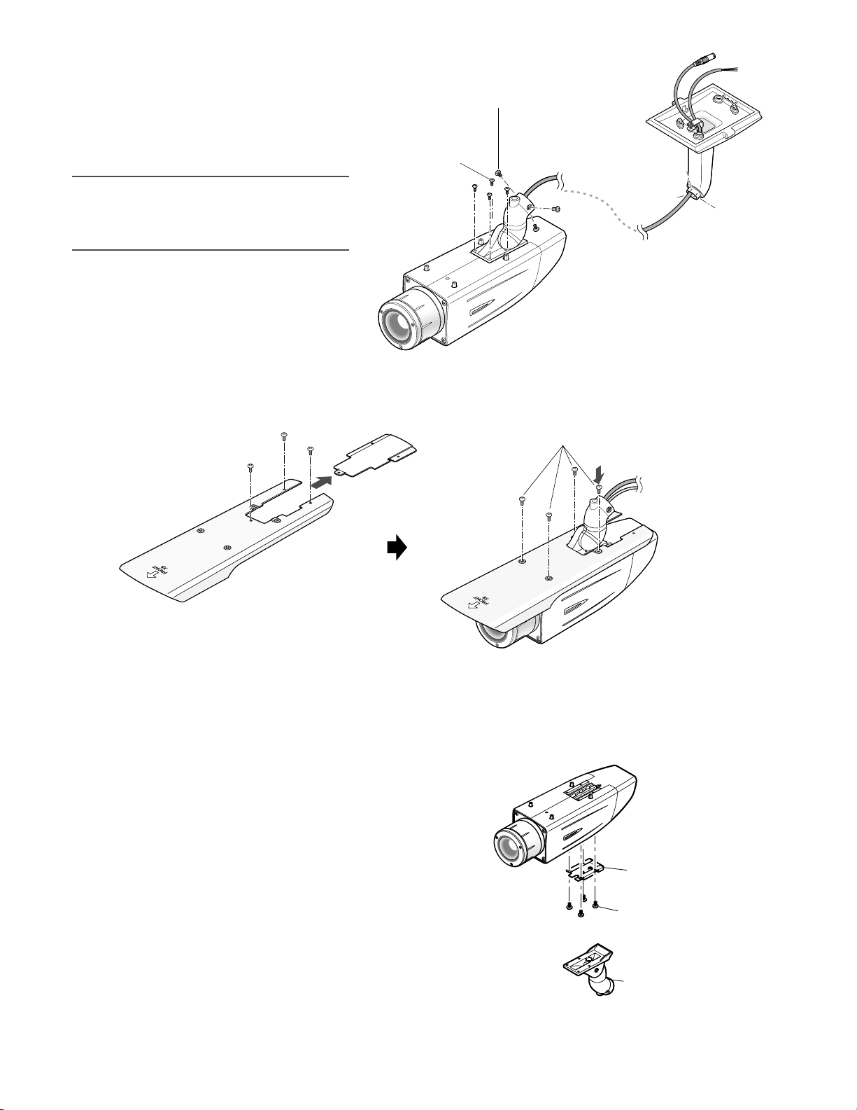
Video output connection
The video output connector is connected to the monitor or
other system devices with a coaxial cable (locally procured).
The maximum extensible length is shown in the table.
* When using 12 V DC power supply,
the heater is unavailable.
• To 24 V AC or 12 V DC power
supply (WV-CW384)
• To 220 V to 240 V AC power
supply (WV-CW380)
Video output cable
(WV-CW384: Approx. 72 cm
WV-CW380: Approx. 72 cm)
Brown (Live)
Blue (Neutral)
Green/Yellow (GND)
To GND
BNC connector
BNC connector
To VIDEO IN
Power cord (WV-CW384: Approx. 72 cm,
WV-CW380: Approx 165 cm)
BNC connector
vMake a connection
Recommended
maximum cable
length
RG-15/U
(10C-2V)
800
RG-11/U
(7C-2V)
RG-6/U
(5C-2V)
RG-59/U
(3C-2V)
Type of coaxial cable
m 600500250
Wire Color 24 V AC 12 V DC
Brown 24 V AC (L) Positive
Blue 24 V AC (N) Negative
Green/Yellow To GND To GND
• ONLY CONNECT THIS TO 24 V AC or 12 V DC CLASS
2 POWER SUPPLY.
• To prevent fire or electric shock hazard, the UL listed
wire VW-1 style 1007 should be used for the cord for
Input Terminals.
• Do not use a transformer larger than 10 VA.
Cord length and wire gauge
<WV-CW384>
24 V AC
The recommended cord length and copper wire size are
shown in the table for reference.
The voltage supplied to the camera should be between
19.5 V AC and 28 V AC.
Copper wire
size (AWG)
Wire length
(Approx.)
#24
(0.22 mm2)
20
#22
(0.33 mm2)
30
#20
(0.52 mm2)
45
#18
(0.83 mm
2
)
75
Recommended wire gauge for 24 V AC line.
m
12 V DC
The recommended resistance and copper wire size are
shown in the table for reference.
The voltage supplied to the camera should be between
10.5 V DC and 16 V DC.
Copper wire
size (AWG)
Resistance (Ω/m)
#24
(0.22 mm2)
0.078
#22
(0.33 mm2)
0.050
#20
(0.52 mm2)
0.03
#18
(0.83 mm2)
0.018
Resistance of copper wire [at 20 °C]
Power connection
Caution:
• The following connections should be made by qualified
service personnel or system installers in accordance
with NEC 725-51.
• Wire colors & functions
Camera power cord
<WV-CW384>
Cautions:
• Be sure to connect the GND (grounding) lead of the
camera and grounding terminal of the power supply
when using a 24 V AC (WV-CW384) or 220 V to 240 V
AC (WV-CW380) power source.
• Shrinking the cord-entry seal is a onetime procedure.
Do not shrink the cord-entry seal until it has been ascertained that unit is functioning.
"L", "R", "V
A ", and "I" shall satisfy the inequality below.
10.5 V DC ≤ V
A - 2(R x I x L) ≤ 16 V DC
L : Cord length (m)
R : Resistance of copper wire (Ω/m)
V
A : DC output voltage of power supply unit
I : DC current consumption (A). See the specification.
Important:
• When using 12 V DC power supply, the heater is
unavailable.
Page 15
15
bBe sure to view the monitor for adjustment
when the camera angle is adjusted.
Supply power to this unit, connect the monitor for adjustment (e.g. a small LCD) to the monitor output jack, and
adjust the camera angle (turn off the power after view angle
adjustment for safety).
1. Loosen the 4 fixing screws of the lens cover to remove
the lens cover.
2. Connect the monitor for adjustment to the monitor output jack.
Note:
• The plug dimensions in the illustration below shall be
observed for the monitor for adjustment.
3. Repeat the steps (1) and (2) to adjust the camera
angle.
(1) Loosen the panning lock screw and rotate the cam-
era head horizontally to adjust panning.
(2) Loosen the tilting lock screw and rotate the camera
head vertically to adjust tilting.
(3) Tighten the panning lock screw and tilting lock
screw after camera angle adjustment.
Important:
• After camera angle adjustment, the panning lock screw
and tilting lock screw shall be securely tightened.
Recommended tightening torque: 2.45 N·m
Notes:
• Use a hexagonal wrench with width across flats of 4
mm (locally procured) to loosen or tighten the panning
lock screw and tilting lock screw.
• Approximately 1 rotation of loosening the panning lock
screw and tilting lock screw allows camera angle
adjustment. Do not loosen the screws beyond necessity.
• The camera body shall be held when the panning lock
screw or tilting lock screw is loosened.
• Focus adjustment (☞ page 16) shall be performed
when panning and tilting adjustments are performed.
Lens cover
Fixing screw x4
Monitor output jack
(ø3.5 mm mini jack (monaural))
9 mm or less
9 mm or less
Straight type L-type
Tilting lock screw
Panning lock screw
Page 16
16
nAdjust the focus
Focus adjustment must be performed when camera angle
(☞ page 15) adjustment are performed.
1. Repeat the steps (1) and (2) to adjust the view angle
and focus.
(1) Rotate the zoom adjustment ring to adjust the view
angle between TELE and WIDE.
(2) Loosen the focus lock knob, make coarse adjust-
ment of the focus, and then tighten the focus lock
knob.
2. Press the auto back focus button after adjusting the view angle while viewing the monitor
for adjustment.
→ The focus position indicator is displayed in the lower part of the screen, and the back
focus is automatically adjusted.
3. To perform fine adjustment of the back focus after automatic back focus adjustment, use the operation buttons through the
setup menu. (☞ page 31)
Notes:
• No operation for 10 seconds or more automatically clears the focus position indicator.
• To change the angle of view by moving the zoom adjustment ring, also move the focus lock knob to adjust the focus.
<How to adjust the focus>
• When an auto iris lens is used to shoot a photographic subject, the originally adjusted focus may be slightly off depending
on the iris state resulting from the focal depth of the lens. In such a case, open the aperture by darkening the subject as
much as possible in the same way of taking picture, and then adjust the focus. Defocus can be prevented.
Use of "ABF" of "BACK-FOCUS SETUP" in the setup menu (☞ page 31) allows users to adjust the focus optimally in the
range of the capability to automatically follow the variation in illuminance. (Note: The adjusted focal point is not necessarily
the same as the optimal focal point at the illuminance.)
• The out-of-focus level in the near-infrared light region may be higher than that in the visible light region.
Setting "C/L ←→ B/W" of "BACK-FOCUS SETUP" to "AUTO" or "PRESET" in the setup menu allows users to adjust the focus
in both the near-infrared light and visible light regions. (The variation in illuminance is not followed after focus adjustment.)
<How to use varifocal lens>
• Reset the back focus position to restore the default position before the back focus adjustment. (Hold down the right and
left buttons among the operation buttons simultaneously for 2 seconds or more, or move the cursor to "MANUAL-ADJ" of
"BACK-FOCUS SETUP" in the setup menu and hold down the right and left buttons simultaneously for 2 seconds or more
after pressing the setting button.)
Auto back focus button
Focus lock knob
NEAR FAR
INDICATOR 80 FOCUSING
Zoom adjustment ring
··········I·········
Page 17
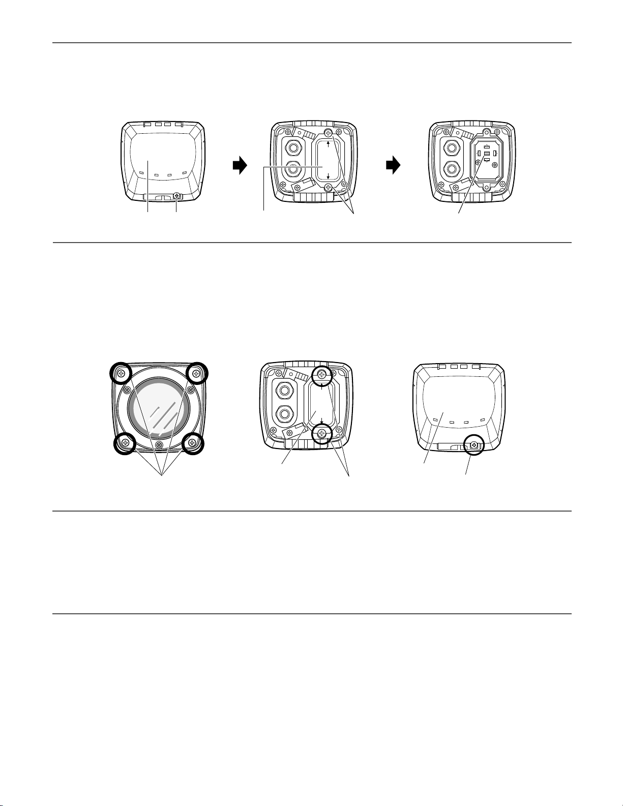
17
<Fine adjustment of the back focus through the setup menu>
1. Loosen the 1 fixing screw of the rear cover to remove the rear cover.
2. Loosen the 2 fixing screws of the switch cover to remove the switch cover.
3. Hold down the setting button for 2 seconds or more to call up the top screen of the setup menu. And then adjust the
back focus. For further information, refer to page 31.
mMount the cover
1. Attach the desiccant (accessory) to the inner bottom side of the lens cover.
2. Mount the lens cover, switch cover, and rear cover.
Important:
• The tightening torque described below shall be followed for the 2 fixing screws of switch cover and the 4 fixing screws of
lens cover.
Recommended tightening torque: 0.59 N·m
• Be sure to attach the desiccant (accessory). Refer to the instructions for the desiccant for how to attach it.
• The tightening sequence of the 4 fixing screws of the lens cover shall be observed and repeated twice as described in the
illustration above.
((1) → (2) → (3) → (4), twice)
Rear cover Fixing screw x1 Switch cover Fixing screw x2
Mouning lens cover
(1)(3)
(4)(2)
Fixing screw x4
Mouning switch cover Mouning rear cover
Fixing screw x2 Fixing screw x1
Set button
Rear coverSwitch cover
Page 18
18
,Mount the sunshield
Mount the sunshield on the camera with the 4 sunshield mounting
screws (accessories).
Notes:
• Be sure to use the 4 sunshield mounting screws (accessories). Recommended tightening torque: 0.59 N·m
• The "FRONT" side of the sunshield shall be on the lens side.
.When the mounting surface is changed to the top surface of the camera body
1. Remove the 4 tripod head fixing
screws from the camera body and
remove the tripod head.
2. Loosen the spacer fixing screw of the
tripod head and remove the spacer.
3. Loosen the fixing screw and remove the rear cover.
4. Position the cable clamp topside to pass the video output cable and power cord upward. And then, mount the
rear cover.
5. Mount the tripod head on the top of the camera body with the 4 tripod head mounting screws that were removed in the
step 1.
Important:
• Caution shall be taken to prevent the video output cable and power cord from being caught between the camera body and
tripod head.
Sunshield mounting screw x4 (M3 x 6) (accessories)
Align the arrow
to lens direction.
Sunshield
Camera main body
Tripod head fixing
screw x4
Spacer
Tripod head
Fixing screw x1Rear cover
Spacer fixing screw
Spacer
Cable clamp
Switch cover
Page 19
19
⁄0When the tripod socket (accessory) is used (when a different camera mount bracket is used)
1. Remove the 4 tripod head fixing screws from the camera body and remove the tripod head.
Disassemble the tripod head and pull out the video output cable and power cord.
2. Mount the tripod socket (accessory) with the 4 mounting
screws for tripod socket (accessories).
7. Mount the sunshield on the camera body with the 4 sunshield mounting screws (accessories) after removing the sunshield
backside.
6. Secure the camera to the camera mount
bracket with the 3 camera fixing screws
(accessories).
Pass the video output cable, and power cord
and safety wire through the camera mount
bracket and secure the safety wire to the
camera mount bracket.
Important:
• Be sure to use the screws that were removed
from the tripod head.
Recommended tightening torque: 0.59 N·m
Camera fixing screw x3
(M4 x 8) (accessories)
Tripod head fixing
screw x4
Camera mount
bracket
Camera main body
Sunshield mounting screw x4 (M3 x 6) (accessories)
Rear part of sunshield
Camera main body
2. Mount the tripod socket
(accessory).
Mounting screw
for tripod socket x4
(M3 x 8) (accessories)
1. Remove the tripod head.
Page 20
20
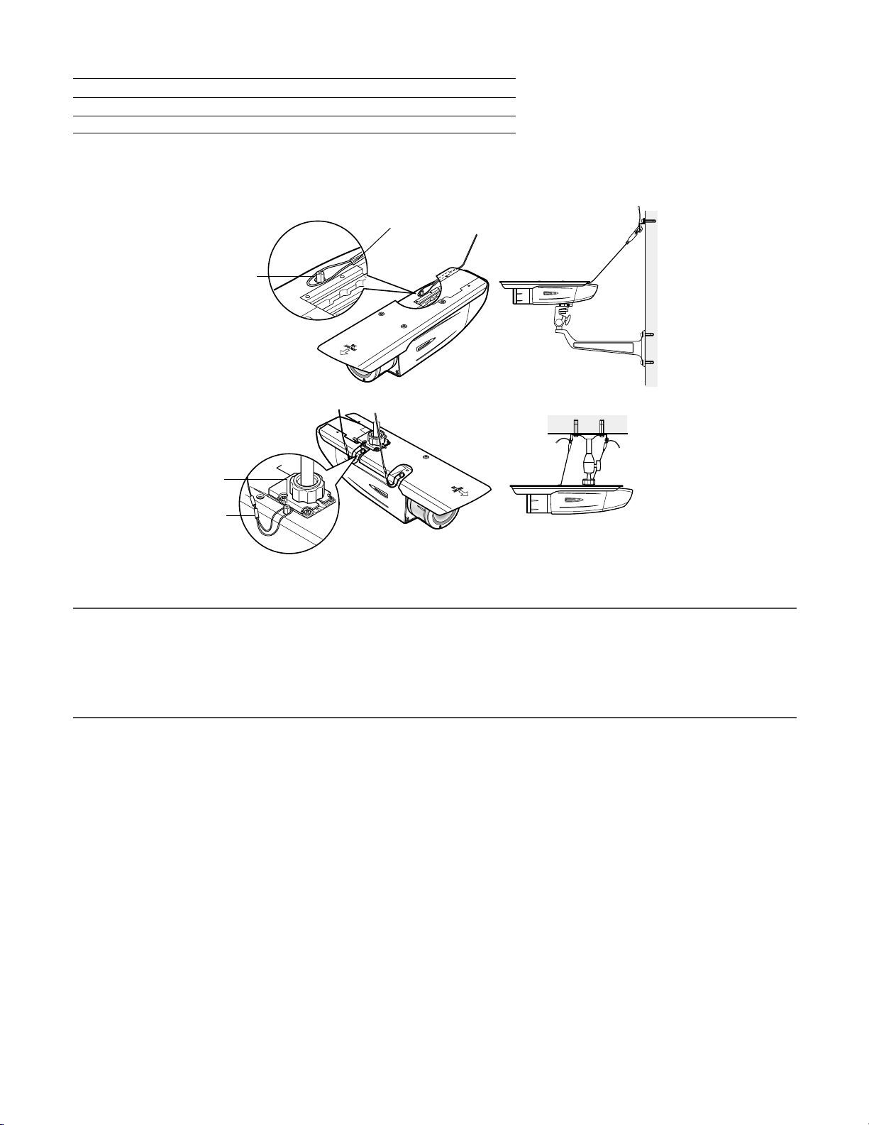
3. Use a safety wire (locally procured) to take measures against a fall of the camera according to the installation position.
Camera mount bracket Safety wire
For wall installation WV-831 WV-Q140
For ceiling installation WV-7010A WV-Q141
4. Hook the tip (ring portion) of the safety wire on the sunshield mounting stud and screw the sunshield to secure the safety
wire.
5. Refer to the instructions of the safety wire for the following steps.
Important:
• Be sure to use the 4 mounting screws for tripod socket (accessories).
Use of screws with inappropriate length may damage the unit.
• The 4 screws removed from the tripod head cannot be used.
• The camera mount brackets, WV-831 and WV-7010A, and the safety wires, WV-Q140 and WV-Q141, are designed to be
used indoors. For outdoor installation, use the camera mount bracket in the accessories.
Safety wire
Sunshield mounting
stud
Wall installation
Sunshield mounting
stud
Safety wire
Ceiling installation
Page 21

21
About Setup Menus
Before operation, setup of this camera is required. On the setup menu, you can check current settings and perform settings to
meet requirements.
The following is an example of setup procedure when "LANGUAGE" is set to "ENGLISH".
Settings items of the camera setup page
Setup item Description
Reference
Pages
CAMERA Configure the settings relating to camera operations
CAMERA ID The camera title can be edited and displayed on the screen.
ALC Configure the light control method.
SHUTTER Select the shutter speed.
AGC Select the method of the gain adjustment.
SENS UP Adjust the sensitivity.
SYNC Configure the method of the synchronization.
WHITE BAL Select the method of the white balance adjustment.
MOTION DET Configure the settings for the motion detection function.
DNR Configure the settings for the DNR (Digital Noise Reduction) function.
RESOLUTION Select a horizontal resolution mode.
BW MODE Configure the settings relating to the BW mode such as the settings for switching
between the color mode and the BW mode.
PRIVACY ZONE It is possible to mask a designated zone and as a privacy zone.
EL-ZOOM Adjust the electronic zoom.
STABILIZER Select "ON" or "OFF" to determine whether or not to use the image stabilizer to pre-
vent shaky images.
LED Performs the settings for LED.
BACK-FOCUS Select the method of the flange-back (back focal) length adjustment and adjust the
flange-back (back focal) length minutely.
SPECIAL
CHROMA GAIN Adjust the chroma level (color density).
AP GAIN Adjust the aperture level.
PEDESTAL Adjust the pedestal level (brightness).
PIX OFF Correct image defects such as scratches.
CAMERA RESET Reset the settings of setup menu to the default settings.
SER.NO. Check the serial number of this camera.
LANGUAGE Select the language to display the setup menu.
23
24
25
26
26
26
27
27
29
29
29
30
30
31
31
31
32
32
32
32
32
33
33
23
Page 22
22
■ Basic operation
The following are descriptions of how to configure each setup item using the operation buttons (refer to page 8) on the camera. Setup using an optional system controller is also available.
Note:
• The illustrations below are the examples to be displayed on a video monitor.
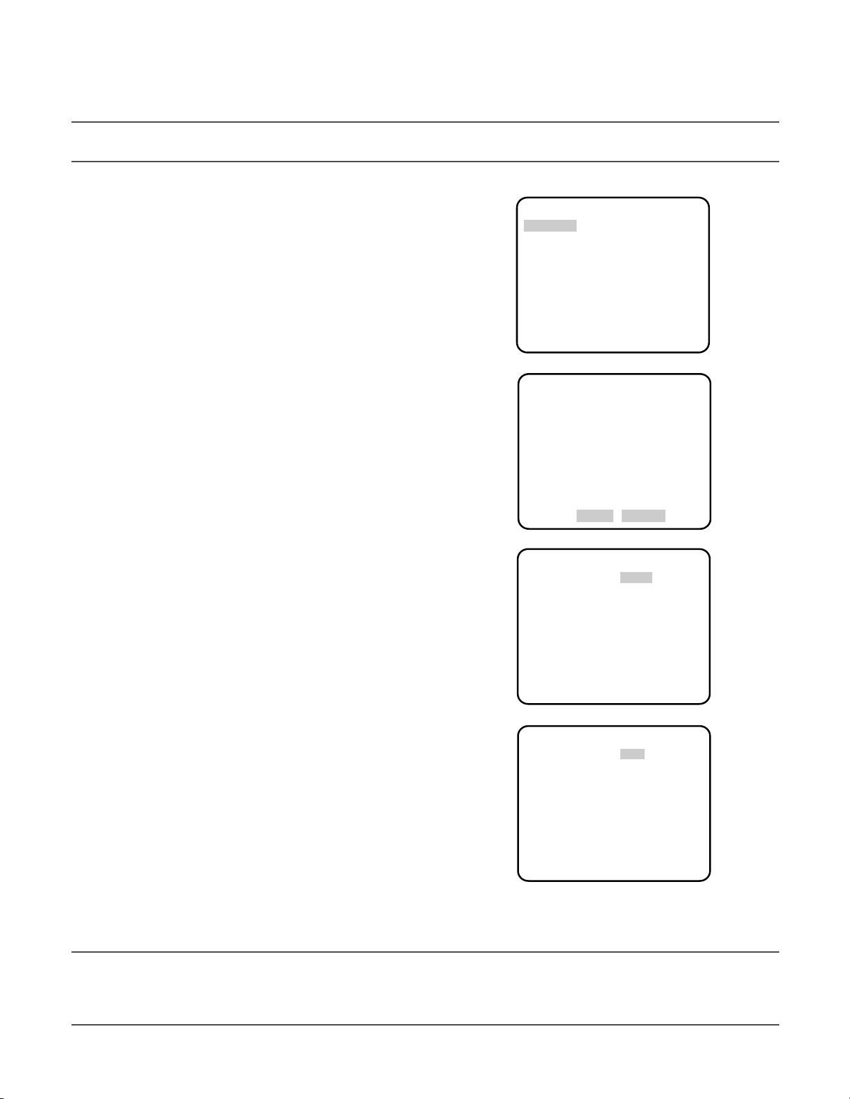
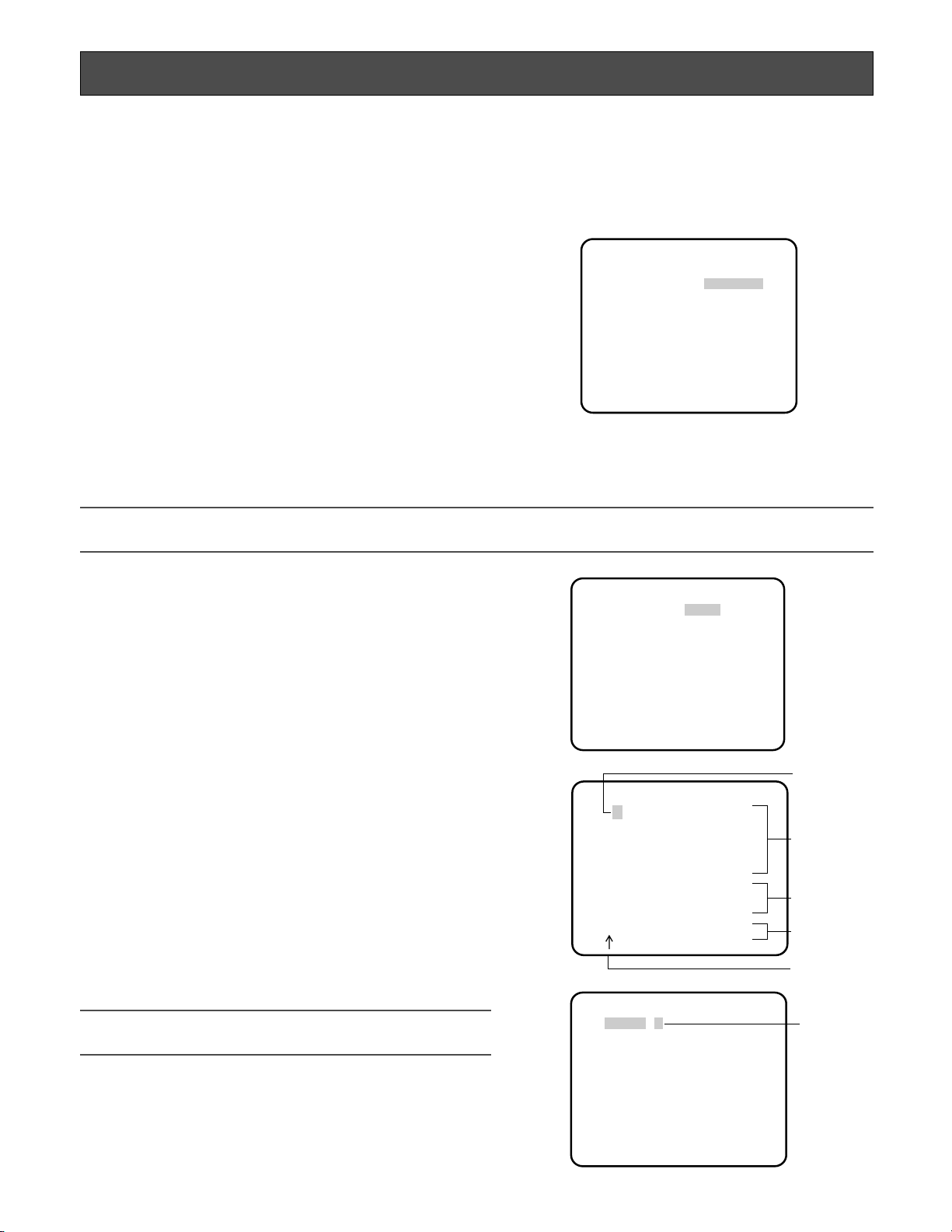
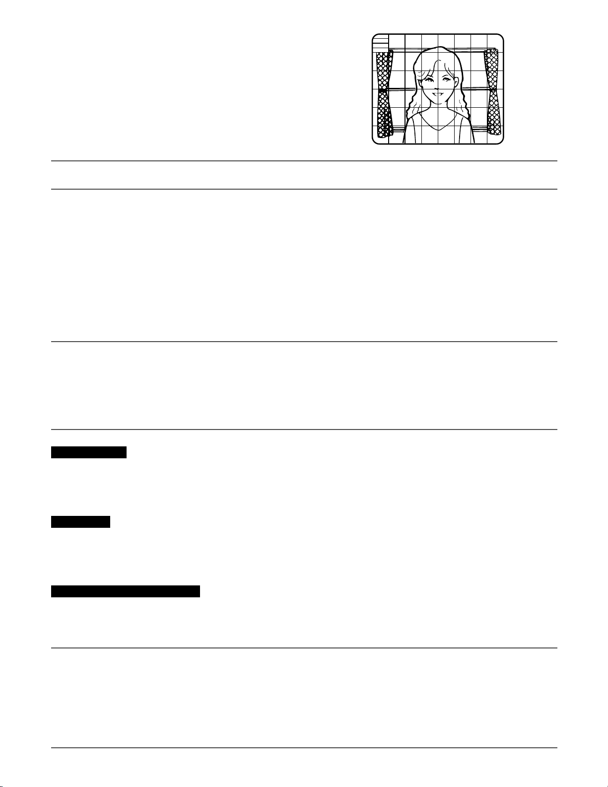
1. Hold down the [SET] button for around 2 seconds.
→ The top page will be displayed.
2. Move the cursor onto "END" by press the [UP] or [DOWN] button.
3. Press the [SET] button after moving the cursor onto "SETUP" by
pressing the [RIGHT] button.
→ The "DISABLE" indication will change into "ENABLE" and
the settings will become editable.
4. Move the cursor onto the desired setup item and press the
[SET] button.
→ The setup page of the selected setup item will be dis-
played.
5. Configure the settings for each item.
Select setup item: Move the cursor by pressing the [UP] or
[DOWN] button.
Change the parameter: Press the [LEFT] or [RIGHT] button.
Display the detailed settings page of the setup item: Press
the [SET] button when the setup item with the [O] mark is
selected.
Go back to the previous page: Move the cursor onto "RET"
and press the [SET] button.
Go back to the top page: Move the cursor onto "TOP" and
press the [SET] button.
6. To exit from the SETUP menu and display images from the camera, move the cursor onto "END" and press the [SET] button.
Notes:
• To prevent erroneous operations, the "DISABLE" indication will always be displayed when the top page is displayed from
the camera. To operate the SETUP menu, switch the "DISABLE" indication to the "ENABLE" indication first.
• The cursor position will be displayed highlighted.
MODEL WV-CW380 SERIES
CAMERA
BACK-FOCUS
SPECIAL
LANGUAGE
O
O
O
O
END SETUP DISABLE
MODEL WV-CW380 SERIES
CAMERA
BACK-FOCUS
SPECIAL
LANGUAGE
O
O
O
O
END SETUP ENABLE
**CAMERA SETUP** 1/2
CAMERA ID OFF
ALC ALC
O
O
SHUTTER OFF
AGC ON(HIGH)
SENS UP OFF
SYNC INT
WHITE BAL ATW1
MOTION DET MODE1
O
O
DNR HIGH
RESOLUTION HIGH
BW MODE
O
**CAMERA SETUP** 2/2
PRIVACY ZONE OFF
EL-ZOOM OFF
STABILIZER OFF
LED ON
RET TOP END
Page 23
23
Setting Procedures
First, select a language for menu display and camera ID display.
Language Setup (LANGUAGE SETUP)
1. Select "LANGUAGE" on the top menu and press the [SET] button.
→ The "LANGUAGE SETUP" menu opens.
2. Select a language. The default setting is "ENGLISH".
Available languages: ENGLISH, FRANÇAIS, ESPAÑOL,
DEUTSCH, ITALIANO, кмллдав, CHINESE or JAPANESE
3. Select "SET" on the menu and press the [SET] button.
1. On the "CAMERA SETUP" menu, select "ONO" or "OFFO" for
"CAMERA ID" and press the [SET] button.
ONO: Displays entered camera ID.
OFFO: Does not display the ID.
→ The "CAMERA ID" menu opens.
2. Select a character from the character area and press the [SET]
button.
→ The selected characters are displayed in the editing area.
1. Camera Identification Setting (CAMERA ID)
Assign a name to the camera using up to 16 characters to display it overlaying on the camera picture in the selected position.
Note:
• If you change the language selection after the assignment of camera ID, it will be erased.
3. Repeat these procedures until all characters are entered.
• To enter a blank space, select "SPACE" and press the [SET]
button.
• To replace a specific character in the editing area:
1. Move the cursor to the editing area and then move the
pointer to the character to be replaced pressing the
[LEFT] and [RIGHT] buttons.
2. Move the cursor to a candidate character in the character
area and press the [SET] button.
• To erase all characters of the camera ID, select "RESET" and
press the [SET] button.
Note:
• For Chinese language, up to 8 characters can be entered.
Character
Cursor
Pointer
Character
Area
Command
Editing
Area
Highlighted
**LANGUAGE SETUP**
LANGUAGE ENGLISH
SET
RET TOP END
**CAMERA SETUP** 1/2
CAMERA ID OFF
ALC ALC
SHUTTER OFF
AGC ON(HIGH)
SENS UP OFF
SYNC INT
WHITE BAL ATW1
MOTION DET MODE1
DNR HIGH
RESOLUTION HIGH
BW MODE
CAMERA ID
0123456789
ABCDEFGHIJKLM
NOPQRSTUVWXYZ
().,'":;&#!?=
+-*/%$
SPACE POSI
RET TOP END RESET
················
O
FLOOR 1
O
O
O
O
Page 24
24
4. To specify the ID display position:
1. Select "POSI" and press the [SET] button.
→ The entered camera ID will be highlighted on the screen.
2. Move it into the appropriate position and press the [SET] button.
→ The position is determined and the screen will return to the "CAMERA ID" menu.
Note:
• Keep pressing any of [LEFT], [RIGHT], [UP], or [DOWN] button for a second or more to move the camera ID faster as necessary.
2. Light Control Mode Setting (ALC)
Select a light control mode depending on the lens type mounted.
ALCO: Is applicable to the auto iris lens. "SUPER-D3" is available with this selection.
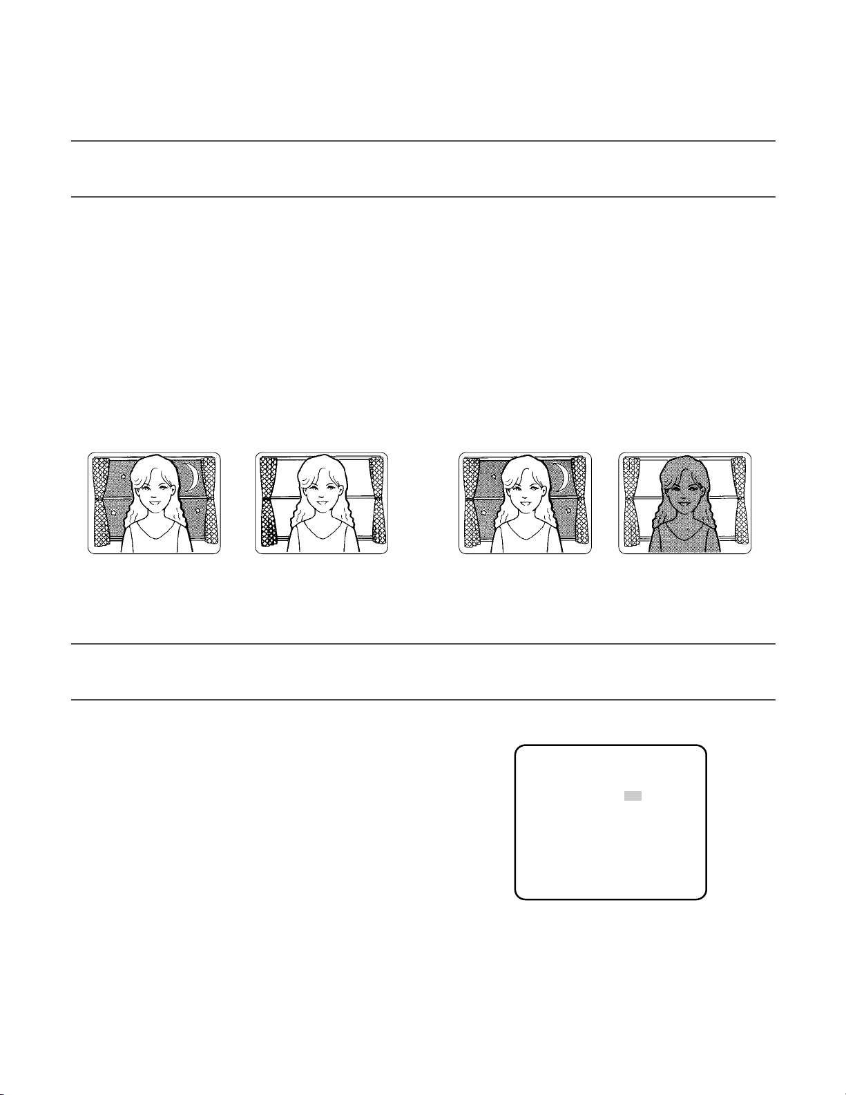
2-1. ALC Mode with SUPER-D3 ON
Super Dynamic 3 Function (SUPER-D3)
In the SUPER-D3 mode, more photometric weight is given to the center of the screen than to the edge where a bright backlight
would most likely be located.
SUPER-D3 ON: Enables SUPER-D3 to compensate backlight automatically.
SUPER-D3 OFF: Enables manual setting to compensate backlight.
Notes:
• When set to "ON", the available parameters for "SHUTTER" and "SENS UP" will be limited as shown on the next page.
• Set "SUPER-D3" to "OFF" when noise in a bright portion, flickerings, or color deterioration are observed.
SUPER-D3 OFF
Nighttime Daytime
SUPER-D3 ON
Nighttime Daytime
1. Move the cursor to "ALC" and press the [SET] button.
→ The "ALC CONT" menu opens.
2. Select "ON" for "SUPER-D3".
3. Adjust the video output level (LEVEL) by moving the "I" cursor.
It may be better to adjust "LEVEL" slightly higher.
**ALC CONT**
BACK LIGHT COMP
SUPER-D3 ON
LEVEL ·I·····
- +
RET TOP END
64
Page 25
25
2-2. ALC Mode with SUPER-D3 OFF
1. Move the cursor to "ALC" on the "CAMERA SETUP" menu and
select "OFF" for "SUPER-D3" on the "ALC CONT" menu.
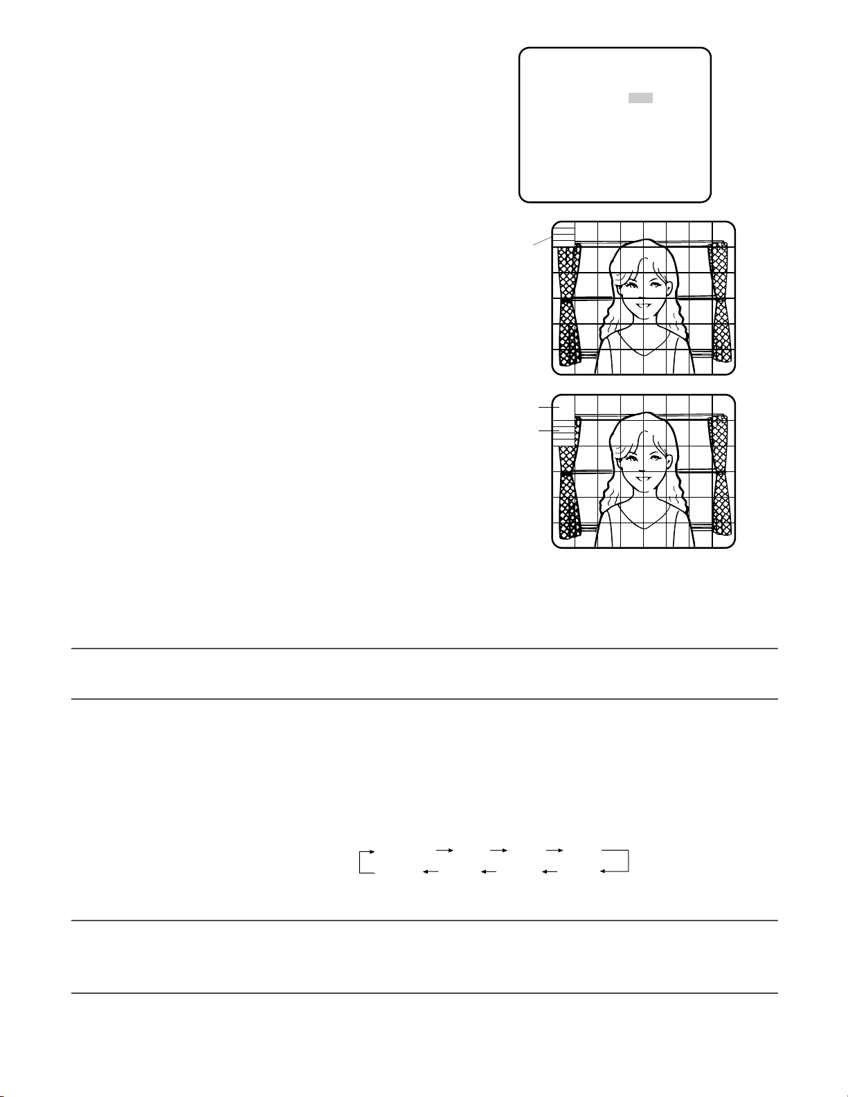
→ "MASK SETO" appears on the "ALC CONT" menu.
2. Select "MASK SET" and press the [SET] button.
→ The 48 mask areas appear overlaid on the camera picture
with the blinking cursor in the upper left corner.
3. Move the cursor to an area where the backlight is bright and
press the [SET] button to mask the area.
→ The masked area appears alternately white and blinking
when the cursor is on the area, or it turns white when the
cursor is on other areas.
4. To cancel masking, move the cursor to a masked area and
press the [SET] button.
→ When masking of the area is cancelled, it changes from
white to normal.
To cancel all the masking, press the [LEFT] and [RIGHT]
buttons simultaneously for 2 seconds or more.
5. Repeat step 3 and 4 as necessary.
3. Shutter Speed Setting (SHUTTER)
Select a proper shutter speed when "ALC" is selected on the "CAMERA SETUP" menu. Selecting a faster speed will reduce
blurring when objects quickly move. The default setting is "OFF".
Blinking
Blinking
White
6. Press the [SET] button for 2 seconds or more.
→ The "ALC CONT" menu appears.
7. Adjust the video output level (LEVEL) by moving "I" cursor.
Note:
• If "ON" is selected for "SUPER-D3", a shadow (black line) may appear at the boundary between the bright and the dim
portions. This is a natural phenomenon and does not indicate trouble.
Notes:
• Only "OFF" is available when "SUPER-D3" is set to "ON".
• When a faster speed is selected for the electronic shutter, the picture will generally become darker, and sometimes a
smear (vertical stripes caused by bright objects) may appear.
**ALC CONT**
BACK LIGHT COMP
SUPER-D3 OFF
MASK SET
LEVEL ·I····· 64
- +
RET TOP END
O
SUPER-D3 OFF:
OFF (1/50) 1/120
1/10000 1/4000 1/2000 1/1000
1/250 1/500
Page 26
26
4. Gain Control Setting (AGC)
Select an automatic gain control mode. This setting raises the gain and brightens the image under low light conditions. The
default setting is "ON (HIGH)".
Available modes: ON (HIGH), ON (MID), ON (LOW), OFF
5. Electronic Sensitivity Enhancement (SENS UP)
Select a proper enhancement rate when the camera is set to ALC mode. The higher rate you select, the brighter the picture will
be. The default setting is "OFF".
AUTO: Sets "AGC" to "ON" and adaptively raises the sensitivity up to the selected amplification rate, for example 10 times
when set to "X10 AUTO".
FIX: Raises the sensitivity fixedly to the selected rate.
OFF: Does not raise the sensitivity.
* Default
Notes:
• Some types of system controllers may not operate some of the SENS UP functions. If this happens, use the operation buttons on the camera.
• When you select "AUTO" for "SENS UP" and "ON" for "SUPER-D3", the SENS UP function has priority so that the SUPER-D3
function is not activated automatically.
• While the SENS UP function is selected, noise, spots or a whitish phenomenon may appear in the picture when the sensitivity of the camera is increased. This is a normal phenomenon.
• Only when "OFF", "X2 FIX", or "X2 AUTO" is selected for sensitivity enhancement (SENS UP), it is possible to perform ABF
adjustment or to select "AUTO" for "C/L ←→ B/W" on the "BACK-FOCUS SETUP" menu. When a sensitivity rate other than
"X2 FIX" or "X2 AUTO" is selected, use "PRESET" and "FIX" for "C/L ←→ B/W" on the "BACK-FOCUS SETUP" menu.
6. Synchronization Setting (SYNC)
1. Select a sync mode.
VD2: Multiplexed vertical drive, highest priority
LL: Line-Lock, follows the phase of supplied AC power, 2nd
priority
INT: Internal sync, lowest priority
Notes:
• Selection is not available when VD2 is added to the camera.
Selection from "LL" is available when the respective sync is
added.
• When "LL" is selected, phase adjustment is required.
2. Line-Lock Vertical Phase Adjustment (V PHASE)
• Select "LL" and press the [SET] button.
• Prepare a dual-trace oscilloscope and supply it with the video output of the camera to be adjusted and that of the refer-
ence camera.
• Set the oscilloscope to the vertical rate and expand the V-sync portion.
• Select a proper "COARSE" phase from 16 steps (22.5 degrees/step) that makes the two video signals on the oscilloscope
the closest.
OFF
SUPER-D3 OFF:
SUPER-D3 ON:
X2 AUTO
X32 FIX X10 FIX X6 FIX X4 FIX X2 FIX
OFF*
X16 FIX
X2 AUTO
X4 AUTO X6 AUTO X10 AUTO
X4 AUTO X6 AUTO X10 AUTO
OFF
**SYNC**
V PHASE
COARSE 1(1--16)
FINE I······ 21
- +
RET TOP END
Page 27
27
• Select a proper "FINE" phase so that the two video signals on the oscilloscope come as close as possible.
Notes:
• Moving the "I" cursor across the +/- end will shift the "FINE" range.
• Press the [LEFT] and [RIGHT] buttons simultaneously to reset the "V PHASE" to the default (0 degree).
• Keep pressing the [LEFT] and [RIGHT] buttons for a second to move the "I" cursor faster if necessary.
• Spike noise if contained in the AC mains may disturb synchronization of LL.
7. White Balance Setting (WHITE BAL)
Select a mode for "WHITE BAL" on the "CAMERA SETUP" menu. The default setting is "ATW1".
ATW1: Is automatically adaptable to the color temperatures of 2 700 K - 6 000 K.
ATW2: Is automatically adaptable to the use of sodium lamps (2 000 K - 6 000 K).
AWC: Is automatically adaptable to the color temperatures of 2 000 K - 10 000 K.
Notes:
• When "ATW1" or "ATW2" is selected, no further operation is required.
• "ATW1" and "ATW2" do not appear on the setup menu of the system controller.
• Select "AWC" in the following cases: the color temperature is out of the 2 000 K - 6 000 K range, the scene contains mostly
high color temperatures such as blue sky or sunset, or the scene is dim.
• When "AWC" is selected, the "AWC" setting is required.
AWC Setting
1. Select "AWC" and press the [LEFT] button.
→ "AWC" will change to "AWC → PUSH SW".
2. Press the [SET] button.
→ "PUSH SW" will be highlighted while the "AWC" setting is
performed.
Note:
• If the white balance is not set, "PUSH SW" is being highlighted.
3. Press the [RIGHT] button.
Manual Fine Adjustment
Perform fine adjustment as necessary.
1. Select "WHITE BAL" and press the [SET] button.
→ Fine adjustment menu of ATW or AWC will open.
2. Adjust finely "R" (Red) and "B" (Blue) gain by moving the "I" cursor.
8. Motion Detection Setting (MOTION DET)
When a series of changes in pictures is detected, the camera outputs an alarm to the external device such as a disk recorder. The
recorder will start recording the pictures.
1. Select a mode for "MOTION DET" on the "CAMERA SETUP"
menu.
The default setting is "OFF".
OFF: Disables the alarm output.
MODE1: Outputs alarm when a series of motions is detected.
MODE2: Outputs alarm when a series of scene changes is
detected.
→ The "MODE1" menu opens when you select "MODE1" and press the [SET] button.
2. Adjust for "LEVEL" to optimize the sensitivity of detection.
**ATW1**
R ···I···129
- +
B ···I···127
- +
RET TOP END
**MODE1**
LEVEL ······I255
- +
DWELL TIME 2S
DISPLAY MODE
ALARM OFF
MASK SET
RET TOP END
O
O
Page 28
28
3. Select a dwell time. The default setting is "2S".
Available time (second): 2, 5, 10, 30
The next detection will be performed after the set time elapses.
4. Select "MASK SET" and press the [SET] button.
→ A 48-split screen opens.
• Specify non-detection (mask) and detection areas in the same
way as described earlier in 2-2 ALC Mode. (☞ page 25)
• Hold down the [SET] button for 2 seconds to return to the
"MODE1" menu.
Note:
• Perform the setting of mask area after "STABILIZER" in the "CAMERA SETUP" menu is set to "OFF".
5. Select "ON" or "OFF" for "ALARM" under "DISPLAY MODE".
ON: Outputs an alarm
OFF: Does not output an alarm. This is applicable any of the following controllers are used: WV-RM70, WV-CU550 series,
WV-CU161, WV-CU360, WV-CU650, WV-CU850, WV-CU950
6. Select "DISPLAY MODE" and press the [SET] button to see the current settings.
When a motion is detected, the area will blink.
• Press the [SET] button to return to the "MODE1" menu.
7. As necessary, repeat to perform "LEVEL" adjustment and "MASK SET" setting by checking on the "DISPLAY MODE" screen.
Important:
• In systems other than Panasonic, select "OFF" for "MOTION DET" to prevent system devices from confusing time-code
signal with alarm signal.
• Set "MASK SET" over the areas where leaves or curtains etc. are swaying.
• Adjust the detection level to prevent detection from confusing motion with noise under low light conditions.
• It takes around 0.2 seconds for the alarm signal to reach the VTR’s alarm terminal after detection.
• The motion/scene change detection is not specifically intended to prevent theft or fire.
Motion Detector
The motion detector divides the screen into 48 blocks and monitors changes in the luminance in each block. When it
detects any change (movement) in the image, it outputs an alarm signal. When a change (movement) in the image is
detected while in the auto mode, the alarm signal is output and the camera stops at the preset position for a specified
amount of time.
Demo Mode
The demo mode divides the screen into 48 blocks and monitors changes in the luminance in each block. It also masks any
part of the picture where there is a change in average luminance that exceeds the currently specified detection sensitivity
level. The demo mode results can be used to determine the optimum detection sensitivity level (step 2) and the areas of
the screen that need to be masked (step 4).
About MODE2 of Motion Detection
The camera will detect a scene change in the following cases.
When the lens is fully sprayed or covered with a cloth, lid, or the like
When the camera direction is suddenly changed
Important:
• The camera will not detect a scene change in the following cases.
When a cloth with patterns covers the lens and it sways in the wind
When some portions in the screen are not veiled
When the screens are similar in scene patterns although the camera direction has changed
• The camera will faultily detect a scene change in the following cases.
When an obvious brightness change arises (ex. On/Off of the lamps)
When objects move continuously such as traffic in busy streets
Page 29

29
9. Digital Noise Reduction Setting (DNR)
Select a "DNR" mode suitable to the camera site conditions. The default setting is "HIGH".
HIGH: Greatly reduces noise, though it produces afterimages when objects move.
LOW: Slightly reduces noise, and produces less afterimages.
10. Resolution Setting (RESOLUTION)
Select a horizontal resolution mode. The default setting is "HIGH".
NORMAL: Resolves more than 480 TV lines.
HIGH: Resolves typically 540 TV lines, though noise may increase when "SENSE UP" is activated in low lighting conditions.
11. Black and White Mode Setting (BW MODE)
1. Select "BW MODE" on the "CAMERA SETUP" menu and press the [SET] button.
→ The "BW MODE" menu opens.
2. Select a mode for "BW". The default setting is "OFF".
→ When "AUTO1" or "AUTO2" is selected, "LEVEL" and "DURATION TIME" appear.
AUTO1: Sets the mode to black-and-white if the picture is dark or to color if the picture is bright enough.
AUTO2: Functions the same as "AUTO1", except this is applied to the use near infrared light. (wavelength ≥ 800 nm).
ON: Sets the mode to black-and-white.
OFF: Sets the mode to color.
Notes:
• There may be cases where "AUTO1" or "AUTO2" does not function well if the camera is aimed at subjects continuously
moving or a scene filled with a single color such as a blue sky.
• It is possible to set up the back-focus mode to compensate for defocus liable to happen when the camera automatically
switches between the color and black-and-white modes. Refer to page 31. Back-focus Setting for details.
3. Select a threshold "LEVEL" to switch between the color and
black-and-white mode. The default setting is "HIGH".
HIGH: Switches the mode at approx. 5 lx illumination.
LOW: Switches the mode at approx. 1 lx illumination.
4. Select a duration time to determine whether to switch the
mode. The default setting is 30 seconds.
Available time: (Short) 10 s ↔ 30 s ↔ 60 s ↔ 300 s (Long)
5. Select a burst signal mode. The default setting is "ON".
ON: Supplies the (color) burst signal with black-and-white composite video.
OFF: Supplies no burst signal.
Note:
• Using "ON" is usually recommended. Try both "ON" and "OFF" to match to connected devices (recorders, monitors, etc.)
that have different characteristics.
**BW MODE**
BW AUTO1
LEVEL HIGH
DURATION TIME ·I··
S L
BURST(BW) ON
RET TOP END
Page 30

30
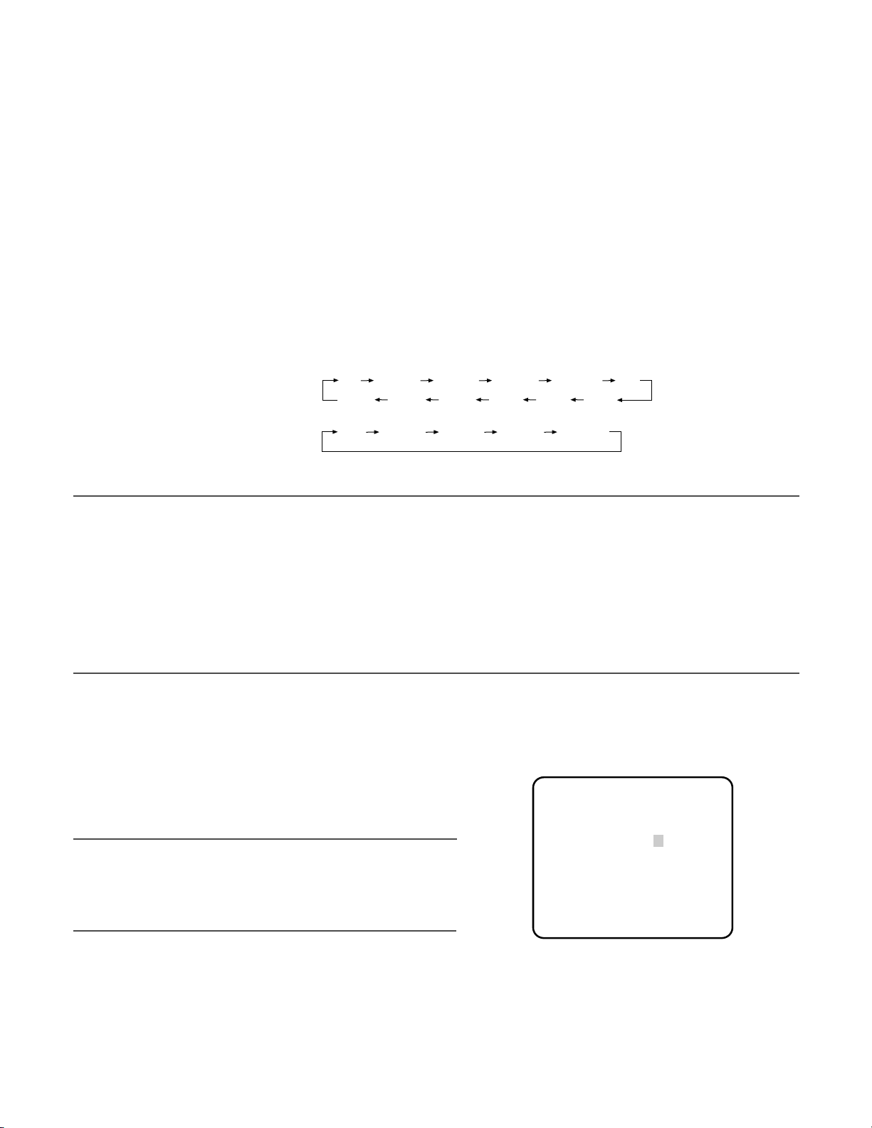
12. Privacy Zone Setting (PRIVACY ZONE)
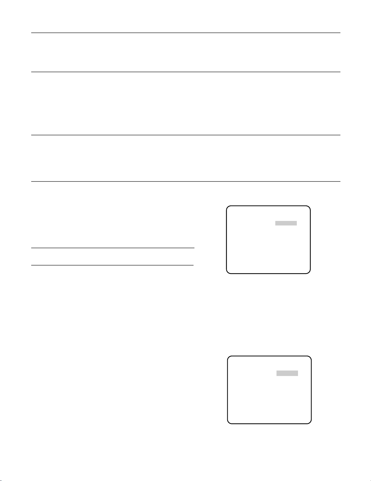
Perform settings of up to eight privacy zones where you wish to veil the monitor screen.
1. Select "ON(1)", "ON(2)" or "OFF" for "PRIVACY ZONE" on page 2 of the "CAMERA SETUP" menu and press the [SET] button.
The default setting is "OFF".
ON (1): Veils the zone with grey.
ON (2): Veils the zone with mosaic.
OFF: Displays pictures normally.
→ The "ZONE NUMBER" selection menu opens.
2. Select a zone number on the top line using the [LEFT] and
[RIGHT] buttons and press the [SET] button. The zone number
followed by an asterisk * indicates that it has been already registered.
→ "POSITION", "SCALE", and a frame appear on the menu.
3. Select "→PUSH SW" for "POSITION" and press the [SET] button.
→ Position selection becomes available.
4. Move the picture portion to be veiled to the center of the frame
using the [LEFT], [RIGHT], [UP], or [DOWN] button.
5. Select "→PUSH SW" for "SCALE" and press the [SET] button.
→ Zone scale adjustment becomes available.
6. Adjust the zone scale using the [LEFT], [RIGHT], [UP], or [DOWN] button.
7. To apply the settings, move the cursor to "SET" and press the [SET] button.
→ The screen returns to the "ZONE NUMBER" selection menu.
To delete the settings, select "DEL" and press the [SET] button.
13. Electronic Zoom (EL-ZOOM)
1. Move the cursor to "EL-ZOOM".
2. Select "ON" or "OFF" by pressing [LEFT] and [RIGHT] buttons.
The default setting is "OFF".
ON: x2 electronic zoom is available with the ZOOM switch on
the controller.
OFF: The electronic zoom function is disabled.
3. While the cursor is on "EL-ZOOM", press the [SET] button. The
"EL-ZOOM" menu appears.
4. Move the cursor to "→PUSH SW" for "ZOOM" and press the
[SET] button to display the "ZOOM" setting menu.
5. Press the [UP] or [DOWN] button to zoom in or out the image.
6. Move the cursor to "→PUSH SW" for "PAN/TILT" and press the
[SET] button. The "PAN/TILT" setting menu appears.
7. Press [LEFT], [RIGHT], [UP], or [DOWN] button to change the
angular field of view.
8. To return to the "EL-ZOOM" menu, press the [SET] button.
**ZONE NUMBER 1 /8**
RET TOP END
**ZONE NUMBER 1 /8**
POSITION
SCALE
SET DEL
RET TOP END
**EL-ZOOM**
PAN/TILT
ZOOM
U TILT D/L PAN R
→
PUSH SW
→
PUSH SW
→
PUSH SW
→
PUSH SW
RET TOP END
**EL-ZOOM**
PAN/TILT
ZOOM
U ZOOM D
RET TOP END
→
PUSH SW
→
PUSH SW
Page 31

31
14. Auto Image Stabilizer (STABILIZER)
This function electronically compensates for an unstable camera image due to movement of a mounting pole or bracket. The
default setting is "OFF".
ON: Automatically compensates for an unstable image.
OFF: Image stabilizer will not operate.
Important:
• When set to "ON", some effective pixels on the edge of the CCD are used by the stabilization function. This may result in a
small reduction in resolution and a narrower angle of view. After activating the image stabilizer function, check that the field
of view is correct.
• Image stabilization may not function where there is excessive camera movement or when the scene is low light or low contrast objects.
15. LED Setting (LED)
"ON" or "OFF" is selected to decide whether or not to use the LED located on the side of this unit. The default setting is "ON".
ON: Blinks the LED when the motion detector function (☞ page 27) detects a change in an image. Lights in the cases other
than the above.
OFF: Keeps the LED unlit.
16. Back-focus Setting (BACK-FOCUS SETUP)
Perform adjustment of the back-focus (flange-back: the gap between the lens and focal plane) remotely on this menu using a
system controller. After installation, you can perform this adjustment when defocus arises that may be caused by long-term use,
environmental changes, etc.
Important:
• Do not use the ABF function for continuous or repetitive purposes (ex. autofocus etc.). This function is to be used to correct defocus caused by switching between color and black and - white when/after installing the camera.
1. Select "BACK-FOCUS " on the top menu and press the [SET] button.
→ The "BACK-FOCUS SETUP" menu opens.
2. Select "ABF" and press the [SET] button.
→ Adjustment is automatically performed.
Notes:
• Performing ABF will function to obtain the best focus around the center areas in a scene.
• Performing ABF is available only when "OFF", "X2 AUTO", or "X2 FIX" is selected for "SENS UP".
• Using the ABF function under low light conditions may cause noise.
3. Select "MANUAL-ADJ" and press the [SET] button if manual adjustment is required.
The manual back-focus adjustment screen will open.
• Use the [LEFT] or [RIGHT] buttons to move the "I" cursor and obtain a proper focus.
→ Refer to the 4-digit number on the second bottom line. The larger the number is, the better the focus will be.
• Select "RET" and press the [SET] button to go back to the menu setup.
4. Select a mode for "C/L ←→ B/W". The default setting is "AUTO".
AUTO: Adjusts the back-focus automatically every time the camera switches the mode between color and black-and-
white. "AUTO" is usable only when "OFF", "X2 AUTO", or "X2 FIX" is selected for "SENS UP".
PRESET: Adjusts the back-focus to the positions for color mode and black-and-white mode that are preset by performing
step 2 (automatic) or step 3 (manual) under the respective light conditions.
**BACK-FOCUS SETUP**
ABF
→
PUSH SW
MANUAL-ADJ
O
C/L←→B/W AUTO
SETUP-SW LOCK OFF
NEAR FAR
·····I·············
INDICATOR 79
RET TOP END
Page 32

32
FIX: Fixes the back-focus after adjustment.
5. Select "ON" or "OFF" for "SETUP-SW LOCK". The default setting is "OFF".
OFF: Enables the [SET] button to open the back-focus adjustment screen while the camera picture is displayed.
ON: Disables the [SET] button from opening the back-focus adjustment screen.
6. To reset the back-focus to the default setting, press the [LEFT] and [RIGHT] buttons simultaneously.
Important:
• Select "FIX" or "PRESET" and adjust manually the back-focus when automatic adjustment is hindered by the following
conditions.
1. Dirt or a water drip attached to window glass
This causes defocus on the object beyond the glass.
2. Objects in low lighting conditions
3. Objects extremely bright
4. Flat contrast objects such as white wall or fine felt
5. Objects placed on the outskirts of the scene
6. More than one object placed with a certain depth
7. An object having a certain depth
8. Objects continuously moving such as busy streets
9. Objects extremely flickering
10. Objects consisting of parallel horizontal lines such as a window shade
• Panasonic Corporation shall not be responsible for any inconvenience, damage or loss caused by or attribute to inappropriate settings for the ABF function.
17. Special Menu (SPECIAL SETUP)
Select "SPECIAL" on the top menu and press the [SET] button.
→ The "SPECIAL SETUP" menu opens.
17-1. Chroma Level Setting (CHROMA GAIN)
Move the "I" cursor to adjust the chroma level.
17-2. Aperture Gain Setting (AP GAIN)
Move the "I" cursor to adjust the aperture gain level.
Lower the level when moire (a kind of noise, optical interference)
appears on the screen as part of minute crosshatch pattern, etc.
17-3. Pedestal Level Setting (PEDESTAL)
Move the "I" cursor to adjust the pedestal level (black level).
17-4. Pixel Compensation Setting (PIX OFF)
Perform settings to compensate a maximum of 16 blemish pixels
on the pickup device.
1. Select "PIX OFF" and press the [SET] button.
→ The "PIX OFF" menu opens with numbers from 1 to 16.
2. Select a number and press the [SET] button.
→ The "PIX OFF" assignment screen opens with a + cursor.
**SPECIAL SETUP**
CHROMA GAIN ····I··160
AP GAIN ··I···· 89
PEDESTAL ····I··171
– +
PIX OFF
O
CAMERA RESET →PUSH SW
SER.NO. 00000000
RET TOP END
**PIX OFF**
1 2 3 4
5 6 7 8
9 10 11 12
13 14 15 16
000 000
RET TOP END
Page 33

33
3. Move the cursor to the center of a blemish position until its
appearance becomes less obvious. Finally, press the [SET]
button.
→ The horizontal and vertical positions (coordinate) of the
blemish will be displayed with a 6-digit number on the second bottom line.
→ The blemish position is registered to be compensated.
→ The screen returns to the "PIX OFF" menu that displays the
number followed by an asterisk if it has been registered.
4. Repeat above steps as necessary.
5. To cancel a registration, select an asterisked number in the "PIX OFF" menu and press the [SET] button.
→ The "PIX OFF" assignment screen opens.
Hold down the the [LEFT] and [RIGHT] buttons simultaneously for 2 seconds or more.
→ The "PIX OFF" menu appears displaying the number without an asterisk if its registration has been cancelled.
17-5. To reset to the default settings (CAMERA RESET)
1. Select "CAMERA RESET".
→ The "→PUSH SW" is highlighted.
2. While holding down the [LEFT] and [RIGHT] buttons, press the [SET] button for 2 seconds or more.
→ The camera will return to the default settings.
Note:
• "PIX OFF" setting cannot be initialized.
17-6. The serial number of the camera will be displayed. (SER. NO.)
Page 34

34
Reference
pages
Cause/solution
Symptom
• Are the power cord and coaxial cable connected appropriately?
→ Check whether the connection is appropriately estab-
lished.
Troubleshooting
No image displayed
Blurred image
Damaged power cord
sheathing
Heated portion of power
cord during use.
Warmed power cord or
loosened connection by
bending or stretching during use.
LED not lit
14
• Is the monitor luminance appropriately adjusted, or is the
contrast appropriately adjusted?
→ Check whether the monitor settings are appropriate.
–
• Is the lens of the camera soiled with dirt or dust?
→ Check whether the lens of the camera is clean.
–
• Is the focus adjusted correctly?
→ Check if the focus is adjusted correctly.
16
• The power cord is damaged.
Use of the damaged cord may cause electric shock or fire.
Turn off the power immediately and request repair to your
dealer.
–
Before asking for repairs, check the symptoms with the following table.
Contact your dealer if a problem cannot be solved even after checking and trying the solution in the table or a problem is not
described below.
• Is power supplied to the camera?
→ Check whether power is supplied to the camera.
• Is "ON" selected for the LED setting?
→ Check whether "ON" is selected for the LED setting.
–
31
Page 35

35
Specifications
● Color CCTV Cameras
Power source and power
consumption: WV-CW384: 24 V AC 50 Hz, 18 W, 12 V DC, 560 mA
WV-CW380: 220 V to 240 V AC, 50 Hz, 14 W
Image sensor: 1/3-inch type interline transfer CCD
Effective pixels: 752 (H) x 582 (V)
Scanning area: 4.8 mm (H) x 3.6 mm (V)
Scanning system: 2:1 interlace
Scanning frequency: Horizontal: 15.625 kHz, Vertical: 50.00 Hz
Synchronization: Multiplexed vertical drive (VD2), line-lock (LL), internal (INT)
Resolution: Horizontal: 570 TV lines (BW mode)
540 TV lines typ., 520 TV lines min. (color mode, resolution: HIGH)
Vertical: 400 TV lines (at center)
Minimum illumination: Color mode:
0.65 lx (sensitivity up OFF, AGC HIGH: F1.6, WIDE)
0.065 lx (sensitivity up 10x, AGC HIGH: F1.6, WIDE)*
BW mode:
0.09 lx (sensitivity up OFF, AGC HIGH: F1.6, WIDE)
0.009 lx (sensitivity up 10x, AGC HIGH: F1.6, WIDE)*
* Converted value
Signal-to-noise ratio: 50 dB (AGC Off)
Dynamic range: 54 dB typ
Video output: 1.0 V[P-P] PAL composite/75 Ω, BNC connector
Monitor output: 1.0 V[P-P] PAL composite/75 Ω, ø3.5 mm mini jack (monaural)
Functions
Camera title: Up to 16 characters (alphanumeric characters, marks)
Light control: ALC
Super-Dynamic 3: ON/OFF
Electronic shutter speed: OFF (1/50), 1/120, 1/250, 1/500, 1/1 000, 1/2 000, 1/4 000, 1/10 000
Gain control: ON (HIGH)/ON (MID)/ON (LOW)/OFF
Sensitivity up: OFF, X2 AUTO, X4 AUTO, X6 AUTO, X10 AUTO, X2 FIX, X4 FIX, X6 FIX, X10 FIX,
X16 FIX, X32 FIX
Synchronization: VD2/LL/INT
White balance: ATW1/ATW2/AWC
Video motion detection: MODE1/MODE2/OFF
Digital noise reduction: HIGH/LOW
Resolution: NORMAL/HIGH
Color/BW: AUTO1/AUTO2/ON/OFF
Privacy zone: ON(1)/ON(2)/OFF
Electronic zoom: ON*/OFF (* Up to 2x)
Image stabilizer: ON/OFF
LED: ON/OFF
Back-focus: ABF (AUTO/PRESET/FIX), MANUAL-ADJ
Special: CHROMA GAIN, AP GAIN, PEDESTAL, PIX OFF
Language: ENGLISH, FRANÇAIS, ESPAÑOL, DEUTSCH, ITALIANO, кмллдав, CHINESE or
JAPANESE
Ambient operating temperature: –30 °C to +50 °C*
* –10 °C to +50 °C at 12 V DC
Ambient operating humidity: 90% or less (no condensation)
Water resistance: Camera: IEC60529 (IP66, Against ingress of water with harmful effects powerful
jetting)*
* Applicable only when the installation and waterproof process are done properly.
Dimensions: 82 (W) mm x 78 (H) mm x 301 (D) mm
Weight: 1.5 kg
Finish: Lens cover: Aluminum die cast with silver metallic coating
Main body: AES resin with silver metallic coating
Page 36

36
● Lens
Focal length: f=5 mm - 40 mm (8x variable focal lens)
F number: F1.6 (WIDE) - F1.9 (TELE)
Focus range: ∞ - 1.2 m
Angle of view: Horizontal: 6.6° (TELE) - 52.0° (WIDE)
Vertical: 5.0° (TELE) - 39.6° (WIDE)
● Camera mount bracket
Adjusting angle: Panning range: ±100°
Tilting range: +30°, –90°
Dimensions: 125 (W) mm x 125 (H) mm x 143 (D) mm
Weight: 240 g
Finish: Aluminum die cast with silver metallic coating
● Adapter box
Dimensions: 133 (W) mm x 133 (H) mm x 50 (D) mm
Weight: 510 g
Finish: Aluminium die cast with silver metallic coating
Weights and dimensions indicated are approximate.
Standard Accessories
Operating Instructions (this document)............................................................................. 1 pc.
The following are for installation.
Camera mount bracket...................................................................................................... 1 pc.
Mount bracket cover.......................................................................................................... 2 pcs.
Sunshield ........................................................................................................................... 1 pc.
Tripod socket..................................................................................................................... 1 pc.
Adapter box....................................................................................................................... 1 pc.
Camera fixing screws (M4 x 8).......................................................................................... 4 pcs.
(incl. 1 spare screw)
Mount bracket cover screws (M3 x 6) ............................................................................... 3 pcs.
(incl. 1 spare screw)
Adapter box mounting screw (M4 x 35) ............................................................................ 1 pc.
Mounting screws for adapter box/camera mount bracket (M5 x 20) ................................ 5 pcs.
(incl. 1 spare screw)
Sunshield mounting screws (M3 x 6)................................................................................. 5 pcs.
(incl. 1 spare screw)
Mounting screws for tripod socket (M3 x 8) ...................................................................... 4 pcs.
Desiccant .......................................................................................................................... 1 pc.
Waterproof tape................................................................................................................. 1 pc.
Page 37

37
Information on Disposal for Users of Waste Electrical & Electronic Equipment (private households)
This symbol on the products and/or accompanying documents means that used electrical and electronic products should not be
mixed with general household waste.
For proper treatment, recovery and recycling, please take these products to designated collection points, where they will be
accepted on a free of charge basis. Alternatively, in some countries you may be able to return your products to your local retailer
upon the purchase of an equivalent new product.
Disposing of this product correctly will help to save valuable resources and prevent any potential negative effects on human
health and the environment which could otherwise arise from inappropriate waste handling. Please contact your local authority
for further details of your nearest designated collection point.
Penalties may be applicable for incorrect disposal of this waste, in accordance with national legislation.
For business users in the European Union
If you wish to discard electrical and electronic equipment, please contact your dealer or supplier for further information.
Information on Disposal in other Countries outside the European Union
This symbol is only valid in the European Union.
If you wish to discard this product, please contact your local authorities or dealer and ask for the correct method of disposal.
Page 38

38
WARNUNG:
• Dieses Gerät muss geerdet werden.
• Alle mit der Installation dieses Produktes verbundenen Arbeiten
sollten von qualifiziertem Kundendienstpersonal oder Systeminstallateuren vorgenommen werden.
• Anschlüsse müssen den örtlichen elektrotechnischen Vorschriften entsprechen.
Wir erklären in alleiniger Verantwortung, daß das Produkt, auf das sich
diese Erklärung bezieht, mit der folgenden Normen oder normativen
Dokumenten übereinstimmt. Gemäß den Bestimmungen der Richtlinie
2006/95/EC und 2004/108/EC.
Das Blitzzeichen mit Pfeil im gleichseitigen
Dreieck soll den Benutzer auf das Vorhandensein von nichtisolierter "gefährlicher
Spannung" innerhalb des Gehäuses hiweisen, die so groß sein kann, daß sie Gefahr
eines elektrischen Schlags darstellt.
Das Ausrufezeichen im gleichseitigen Dreieck soll den Benutzer auf wichtige Bedienungs- und Wartungsanweisungen in den
Unterlagen hinweisen, die dem Gerät beiliegen.
VORSICHT: WEDER DECKEL NOCH RÜCKPLATTE
ABNEHMEN, UM DIE GEFAHR EINES ELEKTRISCHEN
SCHLAGS ZU VERMEIDEN. DAS GERÄT ENTHÄLT
KEINE BAUTEILE, DIE VOM KUNDEN GEWARTET
WERDEN KÖNNEN.
CAUTION
RISK OF ELECTRIC SHOCK
DO NOT OPEN
VORSICHT:
Ein Netzschalter für alle Pole mit einem Kontaktabstand von
mindestens 3 mm für jeden Pol sollte in der elektrischen
Installation des Gebäudes enthalten sein.
ZUR EIGENEN SICHERHEIT BITTE AUFMERKSAM DURCHLESEN.
WARNUNG: Dieses Gerät muß geerdet werden.
WICHTIG
Die Adern dieses Netzkabels sind nach folgendem Code farblich
gekennzeichnet.
Grün-gelb: Erde
Blau: Nulleiter
Braun: Spannungsführend
Da die Farbmarkierung der Adern des Netzkabels dieses Geräts
u.U. nicht mit der Farbmarkierung der Steckerklemmen
übereinstimmt, gehen Sie folgendermaßen vor.
Schließn Sie die grün-gelbe Ader an die mit dem Buchstaben E
oder dem Erdesymbol I oder an die grün oder grün-gelb
gekennzeichnete Steckerklemme an.
Schließn Sie die blaue Ader an die mit dem Buchstaben N oder
an die schwarz gekennzeichnete Steckerklemme an.
Schließn Sie die braune Ader an die mit dem Buchstaben L oder
an die rot gekennzeichnete Steckerklemme an.
VORSICHT:
Bevor Sie dieses Produkt anschließen oder in Betrieb nehmen,
bitte das Schild auf der Unterseite durchlesen.
DEUTSCHE AUSGABE
(GERMAN VERSION)
Schalten Sie den Netzschalter aus, um die
Hauptstromversorgung aller Geräte abzutrennen.
Page 39

39
Wichtige Sicherheitsinstruktionen ................................................................................................................................................. 40
Beschränkung der Haftung ........................................................................................................................................................... 41
Haftungsausschluss ..................................................................................................................................................................... 41
Vorwort ......................................................................................................................................................................................... 42
Merkmale ...................................................................................................................................................................................... 42
Vorsichtsmaßregeln ...................................................................................................................................................................... 43
Wichtige Bedienungselemente und ihre Funktionen .................................................................................................................... 44
Vorsichtshinweise zur Installation ................................................................................................................................................. 45
Installation/Anschlüsse ................................................................................................................................................................. 46
■ Vorbereitungen .................................................................................................................................................................... 46
■ Installation der Kamera ....................................................................................................................................................... 46
Setupmenüs ................................................................................................................................................................................. 57
■ Allgemeine Bedienung ........................................................................................................................................................ 58
Einstellverfahren ........................................................................................................................................................................... 59
Einstellen der Sprache (LANGUAGE SETUP) .......................................................................................................................... 59
1. Einstellen der Kamera-Kennung (KAMERA ID) .................................................................................................................. 59
2. Einstellung der Lichtregelung (ALC) .................................................................................................................................... 60
3. Einstellen der Verschlusszeit (SHUTTER) .......................................................................................................................... 61
4. Einstellen der Verstärkungsregelung (AGC) ....................................................................................................................... 62
5. Elektronische Empfindlichkeitsanhebung (SENS UP) ......................................................................................................... 62
6. Einstellen der Synchronisation (SYNC) ............................................................................................................................... 62
7. Einstellen des Weißabgleichs (WEISSBAL.) ....................................................................................................................... 63
8. Einstellung des Bewegungsmelders (MOTION DET.) ........................................................................................................ 63
9. Einstellen der digitalen Rauschunterdrückung (DNR) ......................................................................................................... 65
10. Einstellen der Auflösung (AUFLÖSUNG) ............................................................................................................................ 65
11. Einstellen des Schwarzweißmodus (S/W MODUS) ............................................................................................................ 65
12. Einstellen von Privatzonen (PRIVATZONE) ........................................................................................................................ 66
13. Elektronisches Zoomen (EL ZOOM) ................................................................................................................................... 66
14. Automatischer Bildstabilisator (STABILIZER) ..................................................................................................................... 67
15. Einstellung der LED (LED) .................................................................................................................................................. 67
16. Rückflanscheinstellung (BACK-FOCUS SETUP) ................................................................................................................ 67
17. Spezialmenü (SPEZIAL SETUP) ........................................................................................................................................ 68
Fehlersuche .................................................................................................................................................................................. 70
Technische Daten ......................................................................................................................................................................... 71
Standardzubehör .......................................................................................................................................................................... 72
INHALT
DEUTSCH
Page 40

40
Wichtige Sicherheitsinstruktionen
1) Bitte lesen Sie diese Instruktionen aufmerksam durch.
2) Bewahren Sie die Instruktionen sorgfältig auf.
3) Befolgen Sie alle Warnungen.
4) Befolgen Sie alle Instruktionen.
5) Reinigen Sie dieses Gerät nur mit einem trockenen Tuch.
6) Blockieren Sie nicht die Belüftungsöffnungen. Installieren Sie das Gerät gemäß den Instruktionen des Herstellers.
7) Installieren Sie dieses Gerät niemals in der Nähe von Wärmequellen wie Heizkörpern, Öfen oder anderen wärmeerzeugenden Apparten (einschließlich Verstärkern).
8) Umgehen Sie niemals die Schutzfunktion des gepolten oder geerdeten Netzsteckers. Ein gepolter Netzstecker weist zwei
Kontaktstifte auf, wobei ein Kontaktstift breiter als der andere ist. Ein geerdeter Netzstecker ist mit zwei Kontaktstiften und
einem dritten Erdungskontakt versehen. Der breite Stift bzw. der dritte Kontaktes dient der Sicherheit. Falls der
mitgelieferte Netzstecker nicht in Ihre Netzdose passt, wenden Sie sich an einen Elektriker, damit dieser die veralterte
Netzdose austauschen kann.
9) Achten Sie darauf, dass nicht auf das Netzkabel getreten oder dieses besonders an den Steckern, an der Netzdose bzw.
am Ausgang aus dem Gerät nicht eingeklemmt wird.
10) Verwenden Sie nur vom Hersteller vorgeschriebene/s Vorrichtungen/Zubehör.
11) Verwenden Sie dieses Gerät nur mit dem vom Hersteller vorgeschriebenen oder mit dem Gerät mitgelieferten Wagen,
Ständer, Stativ oder Tisch. Bei Verwendung eines Wagens ist Vorsicht beim Transport des Geräts auf dem Wagen
geboten, um ein Umkippen und die damit verbundenen möglichen Verletzungen zu vermeiden.
12) Ziehen Sie den Netzstecker dieses Geräts bei Gewittern oder längerem Nichtgebrauch aus der Netzdose.
S3125A
Page 41

41
Beschränkung der Haftung
DIE LIEFERUNG DIESER PUBLIKATION ERFOLGT OHNE
MÄNGELGEWÄHR, WEDER AUSDRÜCKLICH NOCH
STILLSCHWEIGEND, EINSCHLIESSLICH, ABER NICHT
BESCHRÄNKT AUF DIE GESETZLICHE GEWÄHRLEISTUNG DER GEBRAUCHSTAUGLICHKEIT, EIGNUNG ZU
BESTIMMTEN ZWECKEN ODER NICHTVERLETZUNG DER
RECHTE DRITTER.
DIE PUBLIKATION KÖNNTE TECHNISCHE UNGENAUIGKEITEN ODER DRUCKFEHLER ENTHALTEN. IM LAUFE
DER VERBESSERUNG DIESER PUBLIKATION UND/ODER
DER ENTSPRECHENDEN PRODUKTE KANN DER INHALT
JEDERZEIT KORRIGIERT BZW. ERGÄNZT WERDEN.
Haftungsausschluss
Panasonic Corporation IST UNTER ANDEREM IN KEINEM
DER UNTEN AUFGEFÜHRTEN FÄLLE GEGENÜBER
JURISTISCHEN PERSONEN ODER PERSONEN HAFTBAR,
ES SEI DENN ES HANDELT SICH UM EIN BESTIMMTES
VOM ÖRTLICHEN PANASONIC-HÄNDLER
ANGEBOTENES GARANTIEPROGRAMM:
(1) SCHADENSANSPRÜCHE JEGLICHER ART, EIN-
SCHLIESSLICH UND OHNE EINSCHRÄNKUNGEN
UNMITTELBARER, MITTELBARER, ZUSÄTZLICHER,
FOLGE- ODER ÜBER DEN VERURSACHTEN SCHADEN HINAUSGEHENDER SCHADENSANSPRÜCHE;
(2) KÖRPERVERLETZUNGEN ODER SONSTIGE SCHÄ-
DEN, DIE AUF DEN UNSACHGEMÄSSEN GEBRAUCH
ODER DEN FAHRLÄSSIGEN BETRIEB DURCH DEN
BENUTZER ZURÜCKZUFÜHREN SIND;
(3) NICHT ZULÄSSIGES ZERLEGEN, REPARIEREN ODER
VERÄNDERN DES PRODUKTS DURCH DEN BENUTZER;
(4) UNANNEHMLICHKEITEN ODER VERLUST, WENN
BILDER AUS IRGENDWELCHEN GRÜNDEN ODER
URSACHEN NICHT ANGEZEIGT WERDEN, EINSCHLIESSLICH EINES AUSFALLS ODER PROBLEMS
DES GERÄTS;
(5) JEGLICHE STÖRUNGEN, MITTELBARE UNANNEHM-
LICHKEITEN, ODER VERLUSTE ODER SCHÄDEN, DIE
SICH AUS DEM ZUSAMMENSCHALTEN DES
SYSTEMS MIT GERÄTEN VON FREMDHERSTELLERN
ERGEBEN;
(6) JEGLICHE ANSPRÜCHE ODER KLAGEN AUF
SCHADENERSATZ DURCH IRGENDWELCHE PERSONEN ODER ORGANISATIONEN, DIE EIN PHOTOGENES SUBJEKT SIND, HINSICHTLICH EINER
VERLETZUNG DES PERSÖNLICHKEITSRECHTES MIT
DEM ERGEBNIS, DASS BILDER DER ÜBERWACHUNGSKAMERA EINSCHLIESSLICH ABGESPEICHERTER DATEN AUS IRGENDEINEM GRUND
VERÖFFENTLICHT BZW. ZU ANDEREN ZWECKEN
ALS ZUR ÜBERWACHUNG VERWENDET WERDEN.
Page 42

42
Vorwort
Mit den Kameras WV-CW384 und WV-CW380 bietet Panasonic ein hohes Niveau an Bildqualität dank der Verwendung eines
1/3-Zoll-Typ Superdynamik-CCD-Bildaufnahmeelements und LSIs für die digitale Signalverarbeitung. Die Kameras sind für die
Wand- bzw. Deckenmontage an einer Kamera-Einbauplatte.
Merkmale
Einführung von SUPER-D3 (Superdynamik)
Durch Integration von SUPER-D3 mit dem CCD-Bildaufnehmer und der digitalen Signalverarbeitungsschaltung gelang es, den
Dynamikbereich im Vergleich mit herkömmlichen Kameras um rund das 160fach zu erweitern. Auch Szenen, in denen stark
unterschiedliche Ausleuchtung von sehr hell bis dunkel vorkommt, können damit natürlich dargestellt werden.
Mit Rückflansch-Automatik (ABF)
Die Einstellung des Auflagemaßes kann entweder über die Bedienungstasten des Geräts oder über das Setup-Menü erfolgen.
Es kann auch noch nach der Installation des Geräts über das Bediengerät (Option) fern eingestellt werden. Die RückflanschAutomatik kann auch zur Korrektur der oft bei der Umschaltung zwischen Farb- und Schwarzweißbild auftretenden
Fokusabweichung verwendet werden.
Hohe Empfindlichkeit erreicht durch Rauschunterdrückung
Durch die Einführung geräuscharmer Schalttechnik gelang es, die Empfindlichkeit so weit zu steigern, dass Aufnahmen bei
einer Mindestbeleuchtung von nur 0,65 Lux im Farbmodus bzw. 0,09 Lux im Schwarzweißmodus möglich sind.
Nachts automatische Umschaltung auf Schwarzweiß-Bildgabe
Die Umschaltung von Farb- auf Schwarzweiß-Bildgabe bei schwacher Beleuchtung erfolgt automatisch, d.h. Nachtaufnahmen
erfordern keine speziellen Bedienungshandlungen.
Mit Bewegungsmelder
Alarm erfolgt, wenn während der Überwachung auf dem Monitorbildschirm Bewegung erfasst, die Kamera mit einem Tuch,
einer Kappe o.Ä. abgedeckt oder die Kamerarichtung verändert wird.
Page 43

43
Das Gerät besitzt keinen Netzschalter.
Die Versorgung erfolgt über eine externe 12 V Gleichstrom/24 V Wechselstromversorgung (WV-CW384) oder eine 220
bis 240 V Wechselstromversorgung (WV-CW380). Zum Ein/Ausschalten des Stroms wenden Sie sich bitte an einen
Kundendiensttechniker.
Folgende Vorsichtsmaßnahmen treffen, um
zuverlässigen Betrieb aufrechtzuerhalten.
• Der Betrieb des Geräts an Orten, wo es hohen
Temperaturen und hoher Feuchtigkeit ausgesetzt ist,
kann zur vorzeitigen Alterung von Teilen führen und
seine Lebensdauer verkürzen.
Das Gerät nicht direkter Hitzeeinwirkung, wie z.B. von
einer Heizung, aussetzen.
• Das Gerät bei Temperaturen zwischen –30 °C und
+50 °C* und einer Luftfeuchtigkeit von weniger als 90 %
betreiben.
* Bei 12 V Gleichstrom –10 °C bis +50 °C
Verhindern, dass metallische Gegenstände durch die
Gehäuseschlitze ins Innere gelangen.
Dies könnte das Gerät permanent beschädigen. Sofort die
Stromversorgung ausschalten und das Gerät von einem
qualifizierten Kundendiensttechniker warten lassen.
Die Kanten von Metallteilen möglichst nicht mit der
Hand berühren.
Dies könnte zu Verletzungen führen.
Das Gerät unter keinen Umständen zerlegen.
Um elektrische Schläge zu vermeiden, niemals Schrauben
oder Abdeckungen entfernen.
Im Inneren befinden sich keine Teile, die vom Benutzer
gewartet werden können.
Wartungsarbeiten nur von qualifiziertem Kundendienstpersonal vornehmen lassen.
Das Gerät vorsichtig behandeln.
Das Gerät nicht misshandeln. Schläge und Erschütterungen vermeiden.
Falsche Handhabung oder Lagerung kann zu Beschädigungen am Gerät führen.
Reinigen des Gehäuses
Beim Reinigen des Geräts den Strom ausschalten. Einen
trockenen Lappen verwenden, um Schmutz vom Gerät zu
entfernen. Das Gehäuse nicht mit starken oder
scheuernden Mitteln reinigen. Bei hartnäckig anhaftendem
Schmutz mit einem milden Waschmittel vorsichtig
abwischen. Danach das restliche Waschmittel mit einem
trockenen Tuch abwischen.
Andernfalls kann es zu Verfärbungen kommen. Bei
Verwendung eines chemisch imprägnierten Tuches die
diesem beiliegenden Vorsichtshinweise lesen.
Das Objektiv vorsichtig reinigen.
Keine starken oder scheuernden Reinigungsmittel
verwenden. Zur Reinigung Seidenpapier oder ein mit
Ethanol angefeuchtetes Wattestäbchen verwenden.
Verfärbung des CCD-Farbfilters
Bei Langzeitaufnahme einer starken Lichtquelle, z.B. eine
Punktleuchte, kann der Farbfilter im CCD beeinträchtigt
werden, was zu einer Verfärbung des Bildes führen kann.
Diese Verfärbung kann auch dann anhalten, wenn die
Aufnahmerichtung geändert wird, um die Punktleuchte zu
vermeiden.
Vorsichtsmaßregeln
Das Gerät nicht auf helle Lichtquellen richten.
Eine starke Lichtquelle, wie z.B. eine Punktleuchte, kann zu
Leuchtfahnen (Regenbogen) oder zu Überstrahlen
(senkrechte Streifen) führen.
Info zum Entfeuchter
• Das Gerät ist mit einem Entfeuchter ausgestattet, der
das Innere entfeuchtet und so Kondensation und sich
schnell ausbreitende Betauung verhindert.
• Tau kann unter bestimmten Temperatur-, Feuchtigkeits-,
Wind- und Regenverhältnissen entstehen, und die
Entfeuchtung dauert eine gewisse Zeit.
• Die Außenflächen des Entfeuchters unter keinen
Umständen abdichten.
Im Störzustand die Stromversorgung des Geräts am
Leistungsschalter ausschalten.
Das Gerät nicht außerhalb des vorgeschriebenen
Temperatur-, Luftfeuchtigkeits- und Leistungsbereichs
betreiben.
Das Gerät bei Temperaturen zwischen –30°C und +50°C*
und einer Luftfeuchtigkeit von weniger als 90 % betreiben.
Die Versorgungsspannung beträgt 12 V Gleichstrom/24 V
Wechselstrom (WV-CW384) oder 220 bis 240 V Wechselstromversorgung (WV-CW380).
* Bei 12 V Gleichstrom –10 °C bis +50 °C
Einsatz bei kalter Witterung
• Wenn die Kamera bei Temperaturen unter –10 °C
betrieben wird, muss eine Anlaufzeit von mindestens 30
Minuten ab Einschaltung vorgesehen werden.
• Bei Veränderungen der Kameraumgebung wird die
eingebaute Heizung automatisch zu- bzw. abgeschaltet, wobei sich Störungen in der Bildwiedergabe
ergeben können.
Vorgehensweise bei Anzeige von OVER HEAT
Diese Meldung erscheint, wenn sich das Innere des Geräts
stark erhitzt hat. Sofort die Stromversorgung des Geräts
unterbrechen und mit einem Fachhändler beraten.
Überstrahlen
Leuchtfahne
Helles Objekt
Entfeuchter
Page 44

44
q Monitor-Ausgangsbuchse
(Minibuchse ø3,5 mm (mono))
Für den Anschluss an einen Monitor zum Einstellen des
Betrachtungswinkels und Fokus.
w Zoom-Einstellring
Stellt das Zoomverhältnis ein. (☞ Seite 52)
e Rückflansch-Automatik-Taste
Aktiviert die automatische Einstellung des Auflagemaßes.
r Fokus-Feststellschraube
Verriegelt den Brennpunkt. (☞ Seite 52)
t Sonnenblende (Zubehör)
y Frontglas
u Objektivabdeckung
Schützt das Objektiv. Zum Einstellen des Objektivs
muss die Abdeckung abgeschraubt werden. Nach der
Einstellung des Objektivs die Abdeckung wieder mit
den Schrauben sichern. (☞ Seite 51)
i LED-Anzeige
Weist durch Leuchten, Blinken oder Erlöschen auf
Betriebszustände hin. (☞ Seite 67)
o Neigungsfeststellschraube
Verriegelt den eingestellten Neigungswinkel.
(☞ Seite 51)
!0 Schwenk-Feststellschraube
Verriegelt den eingestellten Schwenkwinkel.
(☞ Seite 51)
!1 Netzkabel
Vorsicht:
• Das Netzkabel versorgt das Gerät mit 12 V
Gleichstrom/24 V Wechselstrom (WV-CW384) bzw. 220
bis 240 V Wechselstrom (WV-CW380) von einem
externen Netzteil.
!2 Video-Ausgangskabel
!3 Fangdraht
!4 Rückwärtige Abdeckung
!5 Schalterabdeckung
Diese Abdeckung wird entfernt, um Zugang zu den
Bedienungstasten zu erhalten. Nach der der Betätigung
der Tasten die Abdeckung wieder mit den Schrauben
sichern. (☞ Seite 53)
!6 - @0 Bedienungstasten
!6 Aufwärtstaste (UP)
!7 Rechtstaste (RIGHT)
!8 Abwärtstaste (DOWN)
!9 Linkstaste (LEFT)
@0 Einstelltaste (SET)
@1 Kamera-Einbauplatte (Zubehör)
@2 Adapterdose (Zubehör)
Wichtige Bedienungselemente und ihre Funktionen
e
wq
!6
@0
!8
!9
!7
!5
t
y
u
i
o!0
!2
!3
!4
r
@2
@1
!1
Page 45

45
Einbaustelle
Bei Zweifeln über eine geeignete Einbaustelle unter den
gegebenen Umständen beraten Sie sich bitte mit Ihrem
Fachhändler.
Sicherstellen, dass die Einbaustelle stark genug ist, um das
Gewicht des Geräts zu tragen (z.B. eine Betondecke). Ist
die Einbaufläche nicht stark genug, so muss sie durch
Einbau von Verstärkungen tragfähiger gemacht werden.
Folgende Einbauorte sind zu vermeiden:
• Orte, die chemischen Stoffen ausgesetzt sind, z.B. in
der Nähe eines Schwimmbads
• Orte, wo Dampf und ölige Dünste erzeugt werden, z.B.
eine Küche.
• Orte, an denen entzündbare Gase oder Dünste zugegen sind
• Orte, wo radioaktive oder Röntgenstrahlung erzeugt
wird
• Orte, die starken elektromagnetischen Feldern oder
Radiowellen ausgesetzt sind
• Bereiche, in denen korrosives Gas erzeugt wird
• Orte, wo Schäden durch salzhaltige Luft entstehen
könnten, z.B. in Küstennähe
• Orte, wo die Temperatur nicht im Bereich von –30 °C
bis +50 °C liegt.
* Bei 12 V Gleichstrom –10 °C bis +50 °C
• Vibration ausgesetzte Orte (das Gerät ist nicht für den
Betrieb an Bord eines Fahrzeugs bestimmt.)
Bei Nichtgebrauch sollte das Gerät unbedingt weggeräumt werden.
Weißabgleich
Unter folgenden Umständen kann es vorkommen, dass ein
einwandfreier Weißabgleich nicht möglich ist:
• Bei Objekten, die schneeweiß oder fast einfarbig sind
• Bei Objekten im Freien, die im Morgen- oder Abendlicht
schwach beleuchtet sind
• Bei Objekten, in deren Umgebung stark unterschiedliche Farbtemperaturen vorhanden sind (z.B. bei
Farbbeleuchtung)
Das Video-Ausgangskabel getrennt von Beleuchtungskabeln verlegen.
Dies könnte zu Rauschstörungen führen.
Hochfrequenzstörungen
Bei Verwendung des Geräts in der Nähe einer Fernseh-/
Radioantenne oder eines starken elektrischen oder elektromagnetischen Feldes kann Bildverzerrung oder Rauschen
auftreten. In diesem Fall das Kamerakabel in einem speziellen Kabelkanal verlegen.
Befestigungsschrauben
Mitgeliefert werden lediglich die Schrauben zum Befestigen
des Geräts an der mitgelieferten Einbauplatte. Die
Schrauben bzw. Bolzen für die Montage des Geräts müssen selbst beschafft werden. Sie müssen für das Material
und die Stärke der Einbaufläche des Geräts geeignet sein.
Schrauben und Bolzen müssen mit dem für das Material
und die Stärke der Einbaufläche geeigneten Anzugsmoment festgezogen werden. Nach dem Festziehen die
Schrauben und Bolzen einer Sichtkontrolle unterziehen, um
sicherzustellen, dass sie vorschriftsmäßig angezogen sind
und kein Spiel vorhanden ist.
Kabelrohre
Wird das Gerät im Freien eingesetzt, so muss die
Verkabelung in Kabelrohren verlegt werden, um sie vor
starker Kälte und direkter Sonneneinstrahlung zu schützen.
Vorsichtshinweise zur Installation
Page 46

46
■ Vorbereitungen
Für die Montage stehen zwei Möglichkeiten zur Verfügung.
• Montage der Kamera direkt an der Wand.
• Wandmontage der Kamera mit der Adapterdose
Hinweis:
• Die Schrauben zum Befestigen der Kamera-Einbauplatte sind in der
Lieferung nicht enthalten. Bei der Wahl der Schrauben müssen Faktoren
wie Material, Struktur, Stärke und andere Eigenschaften der Einbaufläche
sowie das Gesamtgewicht der Anbauten berücksichtigt werden.
Wichtig:
• Die Befestigungsschrauben müssen für das Material und die Stärke im Einbaubereich der Kamera-Einbauplatte geeignet
sein. Holzschrauben oder Nägel dürfen nicht verwendet werden. Empfohlenes Anzugsmoment für M4: 1,6 N·m
• Pro Schraube/Bolzen muss eine Ausreißfestigkeit von mindestens 196 N vorhanden sein.
• Wenn die Deckenplatte zu schwach ist, um das Gesamtgewicht zu tragen, muss der Einbaubereich verstärkt werden.
• Bei Verwendung der mitgelieferten Adapterdose diese so anbringen, dass die Entwässerungsschlitze nicht nach oben
zeigen.
■ Installation der Kamera
zMontage der Kamera an der Einbauplatte
Im Lieferzustand ist der Neigungswinkel verriegelt.
1. Die Neigungsfeststellschraube um etwa eine Drehung lösen und die Kamera waagerecht stellen.
2. Dann die Neigungsfeststellschraube wieder festdrehen.
Hinweis:
• Zum Lösen und Anziehen der Neigungsfeststellschraube einen Sechskantschlüssel der Weite 4 mm (selbst zu beschaffen)
verwenden.
3. Das Video-Ausgangskabel, das Netzkabel und den Fangdraht von der Kamera her durch die Kamera-Einbauplatte zur
Wand führen und mit der Kabelklemme bündeln.
Installation/Anschlüsse
Vorsicht:
NUR AN EINE SPANNUNGSVERSORGUNG DER KLASSE 2 FÜR 24 V WECHSELSTROM ODER 12 V GLEICHSTROM
ANSCHLIESSEN. (WV-CW384)
[Position bei Wandmontage]
46 mm
83,5 mm
Anschlussdose (selbst zu beschaffen)
Neigungsfeststellschraube
Kamera
ca. 90°
Page 47

47
4. Die Kamera mit den 3 Schrauben (Zubehör) an der Kamera-Einbauplatte befestigen.
5. Die Schraube aus dem Fangdraht-Befestigungsauge an der Einbauplatte schrauben und den Fangdraht mit der Schraube
sichern.
Wichtig:
• Sicherstellen, dass der Fangdraht sicher befestigt ist. Empfohlenes Anzugsmoment: 0,59 N·m
Wichtig:
<Wasserdichtmachen>
• Bei Installation des Geräts im Freien müssen
die Kabel abgedichtet werden. Die Kamera
selbst ist wasserdicht, aber Einbauplatte
und Adapterdose sind nicht wasserdicht.
• Für den Einsatz im Freien muss auf KameraEinbauplatte, Adapterdose, Kabeldurchführung, Schraubenlöcher und Schrauben
eine Wasserabdichtung wie z.B. Silikongummi aufgebracht werden.
• Beim Montieren des Geräts an der Wand die
Kamera-Einbauplatte so anbringen, dass die Entwässerungsschlitze nach unten weisen. Die Entwässerungsschlitze
nicht blockieren. Ebenso wenig dürfen sie abgedichtet werden.
• Die Anschlussstellen des Netzkabels und des Video-Ausgangskabels durch Umwickeln mit dem mitgelieferten
Abdichtband wasserdicht machen.
<Umwickeln mit Abdichtband>
• Das Band (siehe Abbildung rechts) auf rund doppelte Länge
dehnen und um die Kabel wickeln. Wenn das Band ungenügend
gedehnt wird, ist auch die Wasserabdichtung ungenügend.
• Beim Umwickeln der Kabel sollte sich das Band um eine halbe
Bandbreite überlappen.
Kamera
Kamera-Befestigungsschrauben x3 (M4 x 8) (Zubehör)
Fangdraht
Video-Ausgangskabel
Netzkabel
Kamera-Einbauplatte
Fangdraht-Befestigungsauge
Video-Ausgangskabel
Netzkabel
Kabelklemme
Entwässerungsschlitz
Kamera-Einbauplatte
Netzkabel
Video-Ausgangskabel
Das Band auf rund doppelte Länge dehnen.
Doppelte Länge
Page 48

48
xBefestigen der Kamera-Einbauplatte
• Montage der Kamera direkt an der Wand
Die Kamera-Einbauplatte mit den 4 Schrauben (selbst
zu beschaffen) direkt an einer Wand oder an einer an
der Wand installierten Anschlussdose (selbst zu
beschaffen) befestigen.
Bei Verwendung von Anschlussdosen empfiehlt es
sich, diese gemäß Abbildung rechts nebeneinander zu
installieren (zum Erleichtern der Verkabelung).
• Montage der Kamera über eine Adapterdose an der
Wand
1. Die Adapterdose mit den 4 Schrauben (selbst zu
beschaffen) direkt an einer Wand oder an einer an der
Wand installierten Anschlussdose (selbst zu beschaffen) befestigen.
• Bei Verwendung von Anschlussdosen empfiehlt es
sich, diese gemäß Abbildung rechts nebeneinander zu
installieren (zum Erleichtern der Verkabelung).
6 mm (B) x 10 mm (H)
(Langloch)
Kamera-Einbauplatte
Befestigungsschrauben x4 (selbst zu beschaffen)
46 mm
Kabeldurchführung
83,5 mm
22 mm
6 mm (B) x 10 mm (H)
(Langloch)
Befestigungsschrauben x4 (selbst zu beschaffen)
Bohrung 6 mm (B) x 10 mm (H)
83,5 mm
Kamera-Einbauplatte
46 mm
Mittelpunkt der
Adapterdose
46 mm
Anschlussdosen
Kabeldurchführung
24,5 mm
22 mm
83,5 mm
Befestigungsschrauben x4
(selbst zu beschaffen)
Bohrung
6 mm (B) x 10 mm (H)
Befestigungsschrauben x4
(selbst zu beschaffen)
Adapterdose
Kabeldurchführung (für Verkabelung)
(Innengewinde G3/4")
46 mm
83,5 mm
Anschlussdosen
Page 49

49
2. Die Kamera-Einbauplatte am rechten oder
linken Scharnier der Adapterdose befestigen.
cDie Einbauplattenabdeckungen mit den 2
Schrauben (Zubehör) an der KameraEinbauplatte befestigen.
Hinweis:
• Durch Befestigung am rechten oder linken Scharnier
der Adapterdose soll verhindert werden, dass die
Kamera-Einbauplatte in ihrer Bewegung durch die
Wand usw. behindert wird.
Befestigungsschrauben x4 (M5 x 20) für
Adapterdose/Kamera-Einbauplatte
Befestigungsschrauben (M4 x 35) für Adapterdose
Scharniere
Adapterdose
Einbauplatte
Einbauplattenabdeckung x2
Kamera-Einbauplatte
Befestigungsschrauben x2 (M3 x 6)
für Einbauplattenabdeckung (Zubehör)
Page 50

<WV-CW380>
Vorsicht:
• Bei Verwendung einer 24 V Wechselstrom- (WVCW384) oder 220 - 240 V Wechselstromversorgung
(WV-CW380) die Masseleitung (GND) der Kamera
unbedingt an die Masseklemme des Netzteils anschließen.
Leiterfarben
Braun 220 - 240 V Wechselstrom (L)
Blau 220 - 240 V Wechselstrom (N)
Grün/Gelb An GND
50
Anschluss des Video-Ausgangs
Der Video-Ausgangsverbinder wird über ein Koaxialkabel
(selbst zu beschaffen) an den Monitor oder eine andere
Systemkomponente angeschlossen.
Die maximale Kabellänge ist aus der folgenden Tabelle
ersichtlich.
* Bei Versorgung mit 12 V Gleichstrom
kann die Zusatzheizung nicht betrieben
• An 24 V Wechselstrom- oder
12 V Gleichstromversorgung
(WV-CW384)
• An 220 - 240 V
Wechselstromversorgung
(WV-CW380)
Video-Ausgangskabel
(WV-CW384: ca. 72 cm
WV-CW380: ca. 72 cm)
Braun
(spannungsführend)
Blau (Neutral)
Grün/Gelb (Masse)
An GND
BNC-Stecker
BNC-Stecker
An VIDEO IN
Netzkabel (WV-CW384: ca. 72 cm),
WV-CW380: ca. 165 cm)
BNC-Stecker
vAnschlüsse
Empfohlene
max. Kabellänge
RG-15/U
(10C-2V)
800
RG-11/U
(7C-2V)
RG-6/U
(5C-2V)
RG-59/U
(3C-2V)
Typ Koaxialkabel
m 600500250
Leiterfarben 24 V Wechselstrom 12 V Gleichstrom
Braun 24 V Wechselstrom (L) Positiv
Blau 24 V Wechselstrom (N) Negativ
Grün/Gelb An GND An GND
• Das Aufschrumpfen der Kabeldichtung ist ein einmaliger Vorgang. Mit dem Aufschrumpfen der Kabeldichtung warten, bis bestätigt worden ist, dass das
Gerät funktioniert.
• NUR AN EINE SPANNUNGSVERSORGUNG DER
KLASSE 2 FÜR 24 V WECHSELSTROM ODER 12 V
GLEICHSTROM ANSCHLIESSEN.
• Um Brand und elektrischen Schlag zu verhindern, nach
UL zugelassenes Kabel (VW-1, Ausführung 1007) für
die an die Eingangsklemmen anzuschließenden Kabel
verwenden.
• Keinen Trafo für mehr als 10 VA verwenden.
Kabellängen und Leiterquerschnitte
<WV-CW384>
24 V Wechselstrom
Die folgende Tabelle zeigt die empfohlenen Kabellängen
und Kupferleiterquerschnitte.
Die der Kamera zugeführte Wechselspannung sollte
innerhalb 19,5 V und 28 V liegen.
KupferdrahtQuerschnitt
(AWG)
Leiterlänge
(ca.)
#24
(0,22 mm
2
)
20
#22
(0,33 mm
2
)
30
#20
(0,52 mm
2
)
45
#18
(0,83 mm
2
)
75
Empfohlener Leiterquerschnitt für 24 V Wechselstromkabel
m
12 V Gleichstrom
Die folgende Tabelle zeigt den empfohlenen Widerstand für
die einzelnen Kupferleiterquerschnitte.
Die der Kamera zugeführte Gleichspannung sollte
innerhalb 10,5 V und 16 V liegen.
Für "L", "R", "V
A " und "I" gilt die folgende Ungleichung.
10,5 V Gleichstrom ≤ V
A - 2(R x I x L) ≤ 16 V Gleichstrom
L: Kabellänge (m)
R: Widerstand von Kupferdraht (Ω/m)
V
A: Gleichspannung der Stromversorgung
I: Gleichstromverbrauch (A). Siehe Technische Daten.
Widerstand von Kupferdraht [bei 20 °C]
Netzanschluss
Vorsichtsmaßnahmen:
• Folgende Anschlüsse sollten von einem qualifizierten
Kundendienst- oder Elektroniktechniker in Übereinstimmung mit NEC 725-51 vorgenommen werden.
• Leiterfarben und -funktionen
Kamera-Netzkabel
<WV-CW384>
KupferdrahtQuerschnitt
(AWG)
Widerstand
Ω/m
#24
(0,22 mm
2
)
0,078
#22
(0,33 mm
2
)
0,050
#20
(0,52 mm
2
)
0,03
#18
(0,83 mm
2
)
0,018
m
Page 51

51
Wichtig:
• Bei Versorgung mit 12 V Gleichstrom kann die
Zusatzheizung nicht betrieben werden.
b Bei der Einstellung des Kamerawinkels
das Resultat unbedingt auf dem Einstellmonitor beobachten.
Die Stromversorgung des Geräts einschalten, den Einstellmonitor (z.B. kleines LC-Anzeigegerät) an den MonitorAusgangsbuchse anschließen und den Betrachtungswinkel
der Kamera einstellen (zur Sicherheit anschließend den
Strom ausschalten).
1. Die 4 Befestigungsschrauben der Objektivabdeckung
lösen und diese abnehmen.
2. Den Einstellmonitor an den Monitor-Ausgangsbuchse
anschließen.
Hinweis:
• Bitte die Steckerform für den Anschluss des Einstellmonitors beachten.
3. Die Schritte (1) und (2) wiederholen, bis der Kamerawinkel nach Wunsch eingestellt ist.
(1) Die Schwenk-Feststellschraube lösen und den
Schwenk durch Drehen des Kamerakopfes in der
Horizontalen einstellen.
(2) Die Neigungsfeststellschraube lösen und die
Neigung durch Drehen des Kamerakopfes in der
Vertikalen einstellen.
(3) Anschließend die Schwenk- und Neigungsfeststel-
lschrauben wieder festdrehen.
Wichtig:
• Nicht vergessen, die Schwenk- und Neigungsfeststellschrauben nach dem Einstellen der Kamerawinkels
wieder festzudrehen.
Empfohlenes Anzugsmoment: 2,45 N·m
Hinweise:
• Zum Lösen und Anziehen der Schwenk- und Neigungsfeststellschrauben einen Sechskantschlüssel der Weite
4 mm (selbst zu beschaffen) verwenden.
• Lösen der Schwenk- und Neigungsfeststellschrauben
um etwa eine Drehung ist ausreichend zum Einstellen
des Kamerawinkels. Die Schrauben nicht mehr als
notwendig lösen.
• Beim Lösen der Schwenk- und Neigungsfeststellschrauben ist das Kameragehäuse festzuhalten.
• Die Fokussierung (☞ Seite 52) ist nach der Schwenkund Neigungseinstellung durchzuführen.
Objektivabdeckung
Befestigungsschrauben x4
Monitor-Ausgangsbuchse
(ø3,5 mm Minibuchse (mono))
9 mm oder
weniger
Geradlinig L-förmig
9 mm oder
weniger
Neigungsfeststellschraube
Schwenk-Feststellschraube
Page 52

52
n Fokussierung
Nach dem Einstellen des Kamerawinkels (☞ Seite 51) muss
der Fokus neu eingestellt werden.
1. Die Schritte (1) und (2) wiederholen, bis Betrachtungswinkel and Fokus nach Wunsch eingestellt sind.
(1) Den Betrachtungswinkel durch Drehen des
Zoomrings zwischen TELE und WIDE einstellen.
(2) Die Fokusverriegelung lösen, den Fokus grob
einstellen und die Verriegelung wieder festdrehen.
2. Nach Einstellen des Betrachtungswinkels die Rückflansch-Automatik-Taste drücken und
dabei das Resultat auf dem Einstellmonitor beobachten.
→ Mit der Anzeige des Fokussierwerts unten auf dem Bildschirm wird das Auflagemaß
automatisch eingestellt.
3. Anschließend an die automatische Einstellung kann das Auflagemaß mit den Bedienungstasten oder über das Setup-Menü
noch fein abgestimmt werden. (☞ Seite 67)
Hinweise:
• Die Anzeige des Fokussierwerts wird automatisch gelöscht, wenn innerhalb 10 Sekunden keine Bedienung erfolgt.
• Bei der Einstellung des Betrachtungswinkels mit Hilfe des Zoomrings muss auch die Fokusverriegelung gelöst und der
Fokus eingestellt werden.
<Fokussierung>
• Bei Aufnahmen mit einem Objektiv mit Blendenautomatik kann der ursprünglich eingestellte Fokus aufgrund der sich aus
dem Zustand der Irisblende ergebenden Tiefe der Fokussierebene geringfügig abweichen. In einem solchen Fall die
Blende durch möglichst starkes Abdunkeln des Objekts öffnen und dann den Fokus einstellen. Defokussieren kann
verhindert werden.
Wenn im Setup-Menü (☞ Seite 67) "BACK-FOCUS SETUP" auf "ABF" gesetzt wird, kann der Fokus optimal innerhalb des
Bereichs eingestellt werden, in dem automatisch an Helligkeitsänderungen angepasst wird. (Hinweis: Die eingestellte
Brennweite stimmt nicht unbedingt mit der für die gegebene Beleuchtung optimalen Brennweite überein.)
• Im nahen Infrarotbereich kann die Unschärfe größer sein als im sichtbaren Lichtbereich.
Wenn im Setup-Menü unter "BACK-FOCUS SETUP" der Posten "F ← → B/W" auf "AUTO" oder "PRESET" gesetzt wird, kann
der Fokus sowohl im nahen Infrarotbereich als auch im sichtbaren Lichtbereich optimal eingestellt werden. (Eine
Anpassung an Helligkeitsänderungen erfolgt nach der Fokussierung nicht.)
<Verwendung eines Vario-Objektivs>
• Das Auflagemaß auf den vor der Einstellung bestehenden Vorgabewert zurücksetzen. (Die Rechts- und Linkstasten
(Bedienungstasten) gleichzeitig mindestens 2 Sekunden gedrückt halten oder im Setup-Menü unter "BACK-FOCUS
SETUP" den Cursor auf "MANUELL-JUSTAGE" bewegen, die Einstelltaste drücken und dann die Rechts- und Linkstasten
gleichzeitig mindestens 2 Sekunden gedrückt halten.)
Rückflansch-Automatik-Taste
Fokus-Feststellschraube
NAH WEIT
ANZEIGE 80 FOKUSIER
Zoom-Einstellring
··········I·········
Page 53

53
<Feineinstellung des Auflagemaßes über das Setup-Menü>
1. Die Befestigungsschraube der rückwärtigen Abdeckung lösen und diese abnehmen.
2. Die 2 Befestigungsschrauben der Schalterabdeckung lösen und diese abnehmen.
3. Zum Aufrufen der ersten Seite des Setup-Menüs die Einstelltaste mindestens 2 Sekunden gedrückt halten.
Anschließend den Fokus einstellen. Zu weiteren Informationen siehe Seite 67.
mAnbringen der Abdeckungen
1. Das Trockenmittel (Zubehör) unten in der Objektivabdeckung befestigen.
2. Objektiv-, Schalter- und rückwärtige Abdeckungen anbringen.
Wichtig:
• Das unten angegebene Anzugsmoment gilt für die 2 Befestigungsschrauben der Schalterabdeckung und die 4
Befestigungsschrauben der Objektivabdeckung.
Empfohlenes Anzugsmoment: 0,59 N·m
• Nicht vergessen, das Trockenmittel (Zubehör) anzubringen. Zum Befestigen des Trockenmittels siehe die Anleitung auf
der Packung.
• Die einzuhaltende Reihenfolge beim Festziehen der 4 Befestigungsschrauben der Objektivabdeckung beachten und
zweimal wiederholen (siehe Abbildung oben).
((1) → (2) → (3) → (4), zweimal)
Rückwärtige Abdeckung Befestigungsschraube x1 Schalterabdeckung Befestigungsschraube x2
Einstelltaste
Anbringen der
Objektivabdeckung
(1)(3)
(4)(2)
Befestigungsschrauben x4 Befestigungsschraube x2 Befestigungsschraube x1
Schalterabdeckung
Anbringen der
Schalterabdeckung
Anbringen der
rückwärtigen Abdeckung
Rückwärtige
Abdeckung
Page 54

54
,Anbringen der Sonnenblende
Die Sonnenblende mit den 4 Befestigungsschrauben (Zubehör) an
der Kamera anbringen.
Hinweise:
• Unbedingt die mitgelieferten Schrauben (Zubehör) zum Befestigen der Sonnenblende verwenden. Empfohlenes
Anzugsmoment: 0,59 N·m
• Das mit "FRONT" gekennzeichnete Ende der Sonnenblende muss auf der Objektivseite liegen.
.Vorbereitung für Montage an der Kameraoberseite
1. Die 4 Stativkopfschrauben aus dem
Kameragehäuse herausdrehen und
den Stativkopf abnehmen.
2. Die Befestigungsschrauben der Zwischenplatte lösen und die Zwischenplatte abnehmen.
3. Die Befestigungsschraube der rückwärtigen Abdeckung herausdrehen und die Abdeckung abnehmen.
4. Die Kabelklemme oben anbringen, so dass das VideoAusgangskabel und das Netzkabel nach oben
herausgeführt werden können. Anschließend die
rückwärtige Abdeckung anbringen.
5. Den Stativkopf mit den in Schritt 1 entfernten 4 Schrauben an der Oberseite des Kameragehäuses befestigen.
Wichtig:
• Darauf achten, dass das Video-Ausgangskabel und das Netzkabel nicht zwischen Kameragehäuse und Stativkopf
eingeklemmt werden.
Befestigungsschrauben x4 (M3 x 6)
für Sonnenblende (Zubehör)
Den Pfeil mit dem
Objektiv ausrichten.
Sonnenblende
Kamera
Zwischenplatte
Befestigungsschrauben x4
für Stativkopf
Stativkopf
Abdeckung
Befestigungsschraube x1Rückwärtige
Befestigungsschrauben
für Zwischenplatte
Zwischenplatte
Kabelklemme
Schalterabdeckung
Page 55

55
⁄00Verwendung der Stativfassung (Zubehör) (bei Einsatz einer anderen Kamera-Einbauplatte)
1. Die 4 Stativkopfschrauben aus dem Kameragehäuse herausdrehen und den Stativkopf abnehmen.
Den Stativkopf zerlegen und das Video-Ausgangskabel und das Netzkabel herausziehen.
2. Die Stativfassung (Zubehör) mit den 4 Befestigungsschrauben
(Zubehör) sichern.
7. Die hintere Platte aus der Sonnenblende entfernen und die Sonnenblende mit den 4 Befestigungsschrauben (Zubehör) am
Kameragehäuse anbringen.
6. Die Kamera mit den 3 Schrauben (Zubehör)
an der Kamera-Einbauplatte befestigen.
Das Video-Ausgangskabel, das Netzkabel
und den Fangdraht durch die KameraEinbauplatte führen und den Fangdraht an
der Einbauplatte sichern.
Wichtig:
• Unbedingt die vorher aus dem Stativkopf
entfernten Schrauben verwenden.
Empfohlenes Anzugsmoment: 0,59 N·m
Kamera-Befestigungsschrauben x3
(M4 x 8) (Zubehör)
Befestigungsschrauben x4
für Stativkopf
Kamera-Einbauplatte
Kamera
Befestigungsschrauben x4 (M3 x 6) für
Sonnenblende (Zubehör)
Hintere Platte der
Sonnenblende
Kamera
2. Stativfassung (Zubehör)
montieren.
Befestigungsschrauben x4 (M3 x 8)
für Stativfassung (Zubehör)
1. Stativkopf abmontieren.
Page 56

56
3. Einen Fangdraht (selbst zu beschaffen) als Absicherung gegen ein Herunterfallen der Kamera verwenden.
Kamera-Einbauplatte Fangdraht
Für Wandmontage WV-831 WV-Q140
Für Deckenmontage WV-7010A WV-Q141
4. Das Ende des Fangdrahts (mit Öse) auf den Montagebolzen der Sonnenblende haken und durch Festschrauben der
Sonnenblende sichern.
5. Bei den folgenden Schritten die dem Fangdraht beiliegende Anleitung beachten.
Wichtig:
• Unbedingt die 4 zum Befestigen der Stativfassung mitgelieferten Schrauben (Zubehör) verwenden.
Bei Verwendung von Schrauben ungeeigneter Länge kann das Gerät beschädigt werden.
• Die 4 aus dem Stativkopf entfernten Schrauben können nicht wieder verwendet werden.
• Die Kamera-Einbauplatten WV-831 und WV-7010A sowie die Fangdrähte WV-Q140 und WV-Q141 sind für den Einsatz in
Innenräumen bestimmt. Für den Einsatz im Freien die als Zubehör mitgelieferte Einbauplatte verwenden.
Fangdraht
SonnenblendenMontagebolzen
Wandmontage
SonnenblendenMontagebolzen
Fangdraht
Deckenmontage
Page 57

Einstellposten
KAMERA Den Betrieb der Kamera betreffende Einstellungen vornehmen.
KAMERA ID Der Kameratitel kann bearbeitet und auf dem Bildschirm angezeigt werden.
ALC Das Lichtregelungsverfahren einstellen.
SHUTTER Die Verschlusszeit wählen.
AGC Die Verstärkungsregelung wählen.
SENS UP Die Empfindlichkeit einstellen.
SYNC Das Synchronisationsverfahren einstellen.
WEISSBAL. Das Verfahren des Weißabgleichs wählen.
MOTION DET. Die Einstellungen für den Bewegungsmelder vornehmen.
DNR Die DNR-Funktion (Digitale Rauschreduzierung) einstellen.
AUFLÖSUNG Die horizontale Auflösung wählen.
S/W MODUS Die Einstellungen für den Schwarzweißmodus, wie z.B. die Umschaltung zwischen
Farbe und Schwarzweiß, vornehmen.
PRIVATZONE Bestimmte Zonen als Privatzonen festlegen.
EL ZOOM Den elektronischen Zoom einstellen.
STABILIZER Mit "EIN" oder "AUS" den Verwackelschutz gegen verwackelte Bilder aktivieren- bzw.
deaktivieren.
LED Hier erfolgen die Einstellungen für LED.
BACK-FOCUS Ein Verfahren für die Einstellung des Auflagemaßes (Auflageflanschlänge) wählen
und die Einstellung sehr genau vornehmen.
SPEZIAL
FARBSÄTTIGUNG Den Chromapegel (Farbdichte) einstellen.
APERTURE Die Blendenöffnung einstellen.
PEDESTAL Die Schwarzabhebung (Helligkeit) einstellen.
PIX AUS Bilddefekte wie Kratzer korrigieren.
KAMERA RESET Die Einstellungen im Setupmenü auf die Vorgaben zurücksetzen.
SER.NR Die Fabriknummer der Kamera überprüfen.
LANGUAGE Die Sprache für die Anzeige der Setupmenüs wählen.
57
Setupmenüs
Die Kamera muss vor der Inbetriebnahme eingestellt werden. Im Setupmenü können die gegenwärtigen Einstellungen
überprüft und neue Einstellungen gemacht werden.
Am folgenden Beispiel wird das Einstellverfahren bei Einstellung von "LANGUAGE" auf "DEUTSCH" erläutert.
Inhalt der Kamera-Setupseite
59
60
61
62
62
62
63
63
65
65
65
66
66
67
67
67
68
68
68
68
68
69
69
59
Beschreibung Seitenverweis
Page 58

58
■ Allgemeine Bedienung
Im Folgenden wird die Einstellung der einzelnen Menüposten über die Bedienungstasten der Kamera (siehe S. 44)
beschrieben. Die Einstellung ist auch über ein als Option erhältliches Bedienteil möglich.
Hinweis:
• Die Abbildungen zeigen Beispiele der Anzeige auf dem Videomonitor.
1. Die [SET]-Taste ca. 2 Sekunden gedrückt halten.
→ Das Hauptfenster erscheint.
2. Den Cursor mit der [UP]- oder [DOWN]-Taste auf "END"
bewegen.
3. Den Cursor mit der [RIGHT]-Taste auf "SETUP" bewegen und
die [SET]-Taste drücken.
→ Die Anzeige "INAKTIV" wechselt auf "AKTIV", d.h. die
Einstellposten können geändert werden.
4. Den Cursor auf den gewünschten Einstellposten bewegen und
die [SET]-Taste drücken.
→ Die Einstellseite für den gewählten Einstellposten
erscheint.
5. Für jeden Posten einen Parameter setzen.
Einstellposten wählen: Den Cursor mit der [UP]- oder
[DOWN]-Taste bewegen.
Parameter ändern: Die [RIGHT]- oder [LEFT]-Taste drücken.
Detail-Einstellseite für den Einstellposten aufrufen: Bei
Wahl eines durch [O] gekennzeichneten Einstellpostens
die [SET]-Taste drücken.
Zur vorherigen Seite zurückschalten: Den Cursor auf
"ZURÜCK" bewegen und die [SET]-Taste drücken.
Zur nächsten Seite weiterschalten: Den Cursor auf
"ANFANG" bewegen und die [SET]-Taste drücken.
6. Um das SETUP-Menüzu schließen und Kamerabilder anzuzeigen, den Cursor auf "END" bewegen und die [SET]-Taste
drücken.
Hinweise:
• Um Fehlbedienung zu verhindern, erscheint auf der Hauptseite der Kamera immer die Anzeige "INAKTIV". Um
Einstellungen im SETUP-Menü vorzunehmen, zuerst die Anzeige "INAKTIV" auf "AKTIV" umschalten.
• Die Cursorposition wird hervorgehoben angezeigt.
MODELL WV-CW380 SERIES
KAMERA
BACK-FOCUS
SPEZIAL
LANGUAGE
END SETUP INAKTIV
O
O
O
O
MODELL WV-CW380 SERIES
KAMERA
BACK-FOCUS
SPEZIAL
LANGUAGE
O
O
O
O
END SETUP AKTIV
**KAMERA SETUP** 1/2
KAMERA ID AUS
ALC ALC
O
O
SHUTTER AUS
AGC AUS
SENS UP AUS
SYNC INTERN
WEISSBAL. ATW1
O
MOTION DET. MODE1O
DNR HOCH
AUFLÖSUNG HOCH
S/W MODUS
O
**KAMERA SETUP** 2/2
PRIVATZONE AUS
EL ZOOM AUS
STABILIZER AUS
LED ON
ZURÜCK ANFANG END
Page 59

59
Einstellverfahren
Zunächst eine Sprache wählen, in der die Menüs und Kamerakennungen angezeigt werden sollen.
Einstellen der Sprache (LANGUAGE SETUP)
1. Im Hauptmenü "LANGUAGE" wählen und die [SET]-Taste
drücken.
→ Das "LANGUAGE SETUP"-Menü wird angezeigt.
2. Eine Sprache wählen. Die Vorgabeeinstellung ist "DEUTSCH".
Wählbare Sprachen: ENGLISH, FRANÇAIS, ESPAÑOL,
DEUTSCH, ITALIANO, PìCCKàâ, CHINESE, JAPANESE
3. Im Menü "SET" wählen und die [SET]-Taste drücken.
1. Im "KAMERA SETUP"-Menü "KAMERA ID" auf "EINO" oder
"AUSO" setzen und doe [SET]-Taste drücken.
EINO: Die eingegebene Kamerakennung wird angezeigt.
AUSO: Die Kamera-Kennung wird nicht angezeigt.
→ Das "KAMERA ID"-Menü wird angezeigt.
2. Im Zeichenbereich ein Zeichen wählen und die [SET]-Taste
drücken.
→ Das gewählte Zeichen erscheint im Eingabebereich.
1. Einstellen der Kamera-Kennung (KAMERA ID)
Der Kamera einen aus bis zu 16 Zeichen bestehenden Namen zuweisen, der in der gewählten Position dem Kamerabild
überlagert wird.
Hinweis:
• Eine Kamera-Kennung wird gelöscht, wenn nach deren Eingabe die Sprache gewechselt wird.
3. Den obigen Vorgang wiederholen, bis alle Zeichen eingegeben sind.
• Um eine Leerstelle einzufügen, "SPACE" wählen und die
[SET]-Taste drücken.
• Ersetzen eines bestimmten Zeichens im Eingabebereich:
1. Den Cursor in den Eingabebereich bewegen und
anschließend den Zeiger durch Drücken der [RIGHT]und [LEFT]-Tasten auf das zu ändernde Zeichen
bewegen.
2. Den Cursor auf Zeichenbereich auf das gewünschte
Zeichen bewegen und die [SET]-Taste drücken.
• Um alle Zeichen der Kamerakennung zu löschen, "RESET"
wählen und die [SET]-Taste drücken.
Hinweis:
• Wenn als Sprache Chinesisch gewählt ist, können bis zu 8
Zeichen eingegeben werden.
ZeichenCursor
Zeiger
Zeichenbereich
Befehl
Eingabebereich
Markiert
**LANGUAGE SETUP**
LANGUAGE DEUTSCH
SET
RET TOP END
**KAMERA SETUP** 1/2
KAMERA ID AUS
ALC ALC
SHUTTER AUS
AGC AUS
SENS UP AUS
SYNC INTERN
WEISSBAL. ATW1
MOTION DET. MODE1O
DNR HOCH
AUFLÖSUNG HOCH
S/W MODUS
KAMERA ID
0123456789
ABCDEFGHIJKLM
NOPQRSTUVWXYZ
().,'":;&#!?=
+-*/%$
SPACE POSI
ZURÜCK ANFANG END RESET
················
FLOOR 1
O
O
O
O
Page 60

60
4. Anzeigeposition der Kamerakennung:
1. "POSI" wählen und die [SET]-Taste drücken.
→ Die eingegebene Kamerakennung wird hervorgehoben auf dem Bildschirm angezeigt.
2. In die gewünschte Stelle verschieben und die [SET]-Taste drücken.
→ Die Position wird eingestellt, und die Anzeige schaltet auf das "KAMERA ID"-Menü zurück.
Hinweis:
• Durch Niederhalten der Tasten [RIGHT], [LEFT], [UP] oder [DOWN] für mindestens 1 Sekunde kann die Kamerakennung
schneller auf dem Bildschirm verschoben werden.
2. Einstellung der Lichtregelung (ALC)
Die zum verwendeten Objektivtyp passende Lichtregelung wählen.
ALCO: Lichtregelung für Objektive mit Blendenautomatik. "SUPER-D3" steht bei dieser Wahl zur Verfügung.
2-1. ALC-Modus mit SUPER-D3 EIN
Super-Dynamic 3 (SUPER-D3)
Im SUPER-D3-Modus wird der Mitte des Bildschirms gegenüber den Rändern des Bildschirms (wo das helle Gegenlicht am
häufigsten auftritt) mehr fotometrisches Gewicht zugemessen.
SUPER-D3 EIN: Aktiviert SUPER-D3 für die automatische Kompensation von Gegenlicht.
SUPER-D3 AUS: Aktiviert die manuelle Kompenstion von Gegenlicht.
Hinweise:
• In Stellung "EIN" stehen für "SHUTTER" und "SENS UP" nur die auf der nächten Seite aufgeführten Parameter zur
Verfügung.
• "SUPER-D3" auf "AUS" setzen, wenn Bildrauschen in hellen Bereichen, Flimmern oder eine Verschlechterung der
Farbqualität auftritt.
1. Den Cursor auf "ALC" bewegen und die [SET]-Taste drücken.
→ Das "ALC KONT"-Menü wird angezeigt.
2. Für "SUPER-D3" "EIN" wählen.
3. Den Video-Ausgangspegel (PEGEL) durch Bewegen des "I"-
Cursors verändern. Es empfiehlt sich, "PEGEL" etwas höher
einzustellen.
SUPER-D3 AUS
Nachts Tags
SUPER-D3 EIN
Nachts Tags
**ALC KONT**
BLC
SUPER-D3 EIN
PEGEL ·I····· 64
- +
ZURÜCK ANFANG END
Page 61

61
2-2. ALC-Modus mit SUPER-D3 AUS
1. Den Cursor auf "KAMERA SETUP"-Menü auf "ALC" bewegen,
und im "ALC CONT"-Menü "SUPER-D3" auf "AUS" setzen.
→ Im "ALC CONT"-Menü erscheint der Posten "SETUP
MASKEO".
2. "SETUP MASKE" wählen und die [SET]-Taste drücken.
→ Dem Kamerabild werden 48 Maskenbereiche überlagert,
wobei der Cursor in der oberen linken Ecke blinkt.
3. Den Cursor auf einen Bildbereich bewegen, wo die Hintergrundbeleuchtung stark ist, und diesen Bereich durch
Betätigen der [SET]-Taste maskieren.
→ Der maskierte Bereich blinkt weiß, wenn sich der Cursor
darin befindet, bzw. geht auf weißes Dauerlicht, wenn der
Cursor in anderen Bereichen ist.
4. Um eine Maske aufzuheben, den Cursor auf die Maske
bewegen und die [SET]-Taste drücken.
→ Ein aufgehobener Maskenbereich wechselt von weiß auf
normale Anzeige.
Um alle Masken zu löschen, die [RIGHT]- und [LEFT]Taste gleichzeitig mindestens 2 Sek. drücken.
5. Schritte 3 und 4 nach Bedarf wiederholen.
3. Einstellen der Verschlusszeit (SHUTTER)
Wenn im "KAMERA SETUP"-Menü "ALC" gewählt wurde, eine passende Verschlusszeit wählen. Durch Wahl einer kürzeren
Verschlusszeit kann Unschärfe bei sich schnell bewegenden Objekten verringert werden. Die werksseitige Vorgabeeinstellung
ist "AUS".
6. Die [SET]-Taste mindestens 2 Sekunden.
→ Das "ALC CONT"-Menü wird angezeigt.
7. Den Video-Ausgangspegel (PEGEL) durch Bewegen des "I"-Cursors verändern.
Hinweis:
• Bei Wahl von "EIN" für "SUPER-D3" kann an der Grenze zwischen dem hellen und dem dunklen Bereich ein Schatten
(schwarze Linie) erscheinen. Dies ist normal und stellt keine Störung dar.
Hinweise:
• Wenn "SUPER-D3" auf "EIN" steht, steht nur "AUS" zur Verfügung.
• Bei Wahl einer kürzeren elektronischen Verschlusszeit wird das Bild allgemein dunkler und es kann Überstrahlen (durch
helle Objekte hervorgerufene senkrechte Streifen) auftreten.
Blinkt
Blinkt
Weiß
**ALC KONT**
BLC
SUPER-D3 AUS
SETUP MASKE
PEGEL ·I····· 64
- +
ZURÜCK ANFANG END
O
SUPER-D3 AUS:
AUS (1/50) 1/120
1/10000 1/4000 1/2000 1/1000
1/250 1/500
Page 62

62
4. Einstellen der Verstärkungsregelung (AGC)
Einen Modus für die Verstärkungsregelung wählen. Diese Einstellung hebt die Verstärkung an und erhellt das Bild bei
schlechten Lichtverhältnissen. Die Vorgabe ist "EIN (HOCH)".
Mögliche Einstellungen: EIN (HOCH), EIN (MITTEL), EIN (NIEDRIG), AUS
5. Elektronische Empfindlichkeitsanhebung (SENS UP)
Wenn ALC gewählt wurde, eine passende Empfindlichkeitsanhebung wählen. Je höher der Wert, desto heller wird das Bild.
Die werksseitige Vorgabeeinstellung ist "AUS".
AUTO: Aktiviert "AGC" und hebt die Empflindlichkeit adaptiv an die gewählte Verstärkung an, z.B. 10fach bei Einstellung auf
"X10 AUTO".
FEST: Hebt die Empfindlichkeit fest auf die gewählte Verstärkung an.
AUS: Hebt die Empfindlichkeit nicht an.
* Vorgabe
Hinweise:
•Über einige Bediengeräte lassen sich nur bestimmte SENS UP-Funktionen bedienen. In diesem Fall die Bedienungstasten
an der Kamera benutzen.
• Wenn "SENS UP" auf "AUTO" und "SUPER-D3" auf "EIN" steht, hat SENS UP den Vorrang gegenüber SUPER-D3 und diese
Funktion wird nicht automatisch aktiviert.
• Bei Wahl der SENS UP-Funktion können im Bild Rauschen, Flecken oder Weißfärbung auftreten, wenn die Empfindlichkeit
der Kamera erhöht wird. Dies ist jedoch normal.
• Die ABF-Einstellung oder Wahl von "AUTO" für "F ←→ S/W" im "BACK-FOCUS SETUP"-Menü ist nur dann möglich, wenn
die Empfindlichkeitsanhebung (SENS UP) auf "AUS", "X2 FEST" oder "X2 AUTO" steht. Bei Wahl einer anderen
Empfindlichkeit als "X2 FEST" oder "X2 AUTO" "F ←→ S/W" im "BACK-FOCUS SETUP"-Menü auf "PRESET" und "FEST"
einstellen.
6. Einstellen der Synchronisation (SYNC)
1. Ein Synchronisationsverfahren wählen.
VD2: Multiplex-Vertikalansteuerungssignal, höchste Priorität
NETZSYNC: Zeilensynchronisation, folgt der Phase der Wechselstromversorgung, zweite Priorität
INTERN: Interne Synchronisation, niedrigste Priorität
Hinweise:
• Nicht wählbar, wenn die Kamera mit dem VD2-Signal versorgt
wird. Wählbar bei Einstellung auf "NETZSYNC", wenn der
entsprechende Synchronimpuls zugeführt wird.
• Bei Wahl von "NETZSYNC" ist Phasenabgleich erforderlich.
2. Vertikaler Phasenabgleich bei Zeilensynchronisation (VPHASE)
• "NETZSYNC" wählen und die [SET]-Taste drücken.
• Einen Zweistrahl-Oszillografen bereitstellen und diesem den
Video-Ausgang der einzustellenden Kamera und den einer
Bezugskamera zuführen.
• Den Oszillographen auf Vertikalfrequenz einstellen und die vertikale Synchronisationskomponente auf dem Bildschirm
expandieren.
• Unter den 16 verfügbaren "GROB"-Phasenschritten (22,5 Grad/Schritt) denjenigen auswählen, bei dem die zwei Videosignale auf dem Oszillografen am engsten übereinstimmen.
SUPER-D3 AUS:
SUPER-D3 EIN:
AUS
X32 FEST X10 FEST X6 FEST X4 FEST X2 FEST
AUS*
X2 AUTO
X16 FEST
X2 AUTO
X4 AUTO X6 AUTO X10 AUTO
X4 AUTO X6 AUTO X10 AUTO
AUS
**SYNC**
V-PHASE
GROB 1(1--16)
FEIN I······ 21
- +
ZURÜCK ANFANG END
Page 63

63
• Die "FEIN"-Phase so wählen, dass die zwei Videosignale auf dem Oszillografen möglichst eng übereinstimmen.
Hinweise:
• Durch Bewegen des "I"-Cursors über das +/-Ende hinaus verlagert sich der "FEIN"-Bereich.
• Gleichzeitiges Drücken der [RIGHT]- und [LEFT]-Tasten setzt "V-PHASE" auf die Vorgabe zurück (0 Grad).
• Durch Niederhalten der Tasten [RIGHT] und [LEFT] für 1 Sekunde kann der "I"-Cursor schneller verschoben werden.
• Etwaige Überschwingspitzen auf der Netzleitung können die NETZSYNC-Synchronisation stören.
7. Einstellen des Weißabgleichs (WEISSBAL.)
Im "KAMERA SETUP"-Menü einen Wert für "WEISSBAL." setzen. Die werksseitige Vorgabeeinstellung ist "ATW1".
ATW1: Es passt sich automatisch an Farbtemperaturen im Bereich von 2 700 K - 6 000 K an.
ATW2: Es findet automatische Anpassung bei Natriumlampenbeleuchtung (2 000 K - 6 000 K) statt.
AWC: Es findet automatische Anpassung bei Natriumlampenbeleuchtung (2 000 K -10 000 K) statt.
Hinweise:
• Bei Wahl von "ATW1" oder "ATW2" sind keine weiteren Einstellungen notwendig.
• "ATW1" und "ATW2" sind im Setupmenü des Bediengeräts nicht enthalten.
• In folgenden Fällen "AWC" wählen: Die Farbtemperatur liegt außerhalb des Bereichs von 2 000 K - 6 000 K, die Szene
enthält vorwiegend hohe Farbtemperaturen wie z.B. einen blauen Himmel oder Sonnenuntergang, oder die Szene ist
unterbelichtet.
• Bei Wahl von "AWC" muss die "AWC"-Einstellung vorgenommen werden.
AWC-Einstellung
1. "AWC" wählen und die [LEFT]-Taste drücken.
→ "AWC" wechselt auf "AWC → DRÜCKEN".
2. Die [SET]-Taste drücken.
→ Während der "AWC"-Einstellung wird "DRÜCKEN" her-
vorgehoben.
Hinweis:
• Wurde kein Weißabgleich ausgeführt, wird "DRÜCKEN"
hervorgehoben.
3. Die [RIGHT]-Taste drücken.
Manueller Feinabgleich
Nach Bedarf Feinabgleich vornehmen.
1. "WEISSBAL." wählen und die [SET]-Taste drücken.
→ Das Feinabgleichmenü für ATW bzw. AWC erscheint.
2. Durch Bewegen des "I"-Cursors die "R" (Rot)- und "B" (Blau)-Verstärkung fein abgleichen.
8. Einstellung des Bewegungsmelders (MOTION DET.)
Wenn eine Serie von Bewegungen in Bildern erfasst wird,
überträgt die Kamera ein Alarmsignal zu einem externen Gerät,
z.B. Digitalrekorder. Der Rekorder beginnt mit der Aufzeichnung
der Bilder.
1. Im "KAMERA SETUP"-Menü einen Wert für "MOTION DET."
setzen.
Die werksseitige Vorgabeeinstellung ist "AUS".
AUS: Deaktiviert den Alarmausgang.
MODE1: Überträgt ein Alarmsignal, wenn eine Serie von
Bewegungen erfasst wird.
MODE2: Überträgt ein Alarmsignal, wenn eine Serie von
Szenenwechseln erfasst wird.
→ Um das "MODE1"-Menü zu öffnen, "MODE1" wählen und die [SET]-Taste drücken.
2. "PEGEL" für optimale Ansprechempfindlichkeit des Detektors einstellen.
**ATW1**
R ···I···129
- +
B ···I···127
- +
ZURÜCK ANFANG END
**MODE1**
PEGEL ······I255
- +
VERWEILZEIT 2S
ANZEIGE MODUS
ALARM AUS
SETUP MASKE
ZURÜCK ANFANG END
O
O
Page 64

64
3. Verweilzeit wählen. Die Vorgabeeinstellung ist "2S".
Einstellzeiten (Sekunden): 2, 5, 10, 30
Die nächste Erfassung erfolgt nach Ablauf der eingestellten
Zeitspanne.
4. "SETUP MASKE" wählen und die [SET]-Taste drücken.
→ Ein in 48 Segmente unterteilter Bildschirm erscheint.
• Von der Erfassung auszuschließende (maskierte) Bereiche
und Erfassungsbereiche analog 2-2 ALC-Modus festlegen.
(☞ Seite 61)
• Durch Niederhalten von [SET]-Taste für 2 Sekunden zum
"MODE1"-Menü zurückschalten.
Hinweis:
• Bevor Maskenbereiche festgelegt werden, im "KAMERA SETUP"-Menü "STABILIZER" auf "AUS" setzen.
5. Unter "ANZEIGE MODUS" den Posten "ALARM" auf "EIN" oder "AUS" setzen.
EIN: Alarmausgang
AUS: Kein Alarmausgang. Dies gilt bei Verwendung eines der folgenden Bediengeräte: Serie WV-RM70, WV-CU550,
sowie WV-CU161, WV-CU360, WV-CU650, WV-CU850, WV-CU950
6. Zum Einsehen der aktuellen Einstellungen "ANZEIGE MODUS" wählen und die [SET]-Taste drücken.
Wenn Bewegung erkannt wird, blinkt der entsprechende Bereich.
• Durch Drücken der [SET]-Taste zum "MODE1"-Menü zurückschalten.
7. Die "PEGEL"- und "SETUP MASKE"-Einstellungen unter Beobachtung des "ANZEIGE MODUS"-Bildschirms nach Bedarf
wiederholen.
Wichtig:
• Bei Systemen anderer Hersteller als Panasonic "MOTION DET." auf "AUS" stellen, um zu verhindern, dass die
Systemgeräte das Timecode-Signal fälschlich als Alarmsignal interpretieren.
• Mit "SETUP MASKE" Bereiche maskieren, in denen im Wind flatternde Gegenstände wie Blätter oder Vorhänge
vorhanden sind.
• Die Ansprechempfindlichkeit des Detektors so einstellen, dass Rauschen bei schwacher Beleuchtung nicht irrtümlich
als Bewegung erkannt wird.
• Vom Zeitpunkt der Erfassung bis zum Eingang des Alarmsignals am Alarmeingang des Videorekorders vergehen ca.
0,2 Sekunden.
• Der Bewegungsmelder ist nicht speziell für die Verhinderung von Diebstahl oder Brand bestimmt.
Bewegungsmelder
Der Bewegungsmelder unterteilt den Bildschirm in 48 Bereiche und überwacht Veränderungen des Helligkeitspegels in
den einzelnen Bereichen. Wenn eine Veränderung (Bewegung) erfasst wird, wird ein Alarmsignal ausgegeben. Wird im
Auto-Modus eine Veränderung (Bewegung) im Bild erkannt, so wird ein Alarmsignal ausgegeben und die Kamera bleibt
für die festgelegte Dauer in der Preset-Position stehen.
Demonstrationsmodus
Der Demonstrationsmodus unterteilt den Bildschirm in 48 Bereiche und überwacht Veränderungen des Helligkeitspegels in
den einzelnen Bereichen. Außerdem werden solche Bilder maskiert, in denen eine die eingestellte
Ansprechempfindlichkeit des Detektors überschreitende Veränderung des Helligkeitspegels festgestellt wird. Anhand der
im Demonstrationsmodus erzielten Ergebnisse kann die optimale Ansprechempfindlichkeit (Schritt 2) sowie die
Bildschirmbereiche, die maskiert werden müssen (Schritt 4), bestimmt werden.
MODE2 des Bewegungsmelders
Die Kamera erkennt in folgenden Fällen einen Szenenwechsel.
Wenn das Objektiv vollständig besprüht oder mit einem Tuch, Deckel o.ä. abgedeckt wird
Wenn die Kamerarichtung plötzlich verändert wird
Wichtig:
• In folgenden Fällen erkennt die Kamera keinen Szenenwechsel.
Wenn das Objektiv mit einem gemusterten Tuch abgedeckt wird und dieses im Wind flattert
Wenn einige Abschnitte des Bildes nicht verschleiert sind
Wenn die Kamerarichtung verändert wird, aber die Aufnahmeszenen ähnlich sind
• Die Kamera erkennt in folgenden Fällen fälschlich einen Szenenwechsel.
Wenn die Helligkeit aus offensichtlichen Gründen wechselt (z.B. Ein-/Ausschalten von Lampen)
Bei ständig in Bewegung befindlichen Objekten wie der Straßenverkehr
Page 65

65
9. Einstellen der digitalen Rauschunterdrückung (DNR)
Einen für den Standort der Kamera geeigneten "DNR"-Modus wählen. Die werksseitige Vorgabeeinstellung ist "HOCH".
HOCH: Rauschen wird erheblich reduziert, aber bei bewegten Objekten kann es zu Nachzieheffekt kommen.
NIEDRIG: Rauschen wird geringfügig reduziert, aber es tritt weniger Nachzieheffekt auf.
10. Einstellen der Auflösung (AUFLÖSUNG)
Die horizontale Auflösung wählen. Die werksseitige Vorgabeeinstellung ist "HOCH".
NORMAL: Erzielt eine Auflösung von mehr als 480 Fernsehzeilen.
HOCH: Erzielt eine typische Auflösung von 540 Fernsehzeilen, kann aber zu erhöhtem Rauschen führen, wenn bei schwacher
Beleuchtung "SENS UP" aktiviert ist.
11. Einstellen des Schwarzweißmodus (S/W MODUS)
1. Im "KAMERA SETUP"-Menü "S/W MODUS" wählen und die [SET]-Taste drücken.
→ Das "S/W MODUS"-Menü wird angezeigt.
2. Für "BW" einen Modus wählen. Die werksseitige Vorgabeeinstellung ist "AUS".
→ Bei Wahl von "AUTO1" oder "AUTO2" werden die Posten "PEGEL" und "ZEITDAUER" angezeigt.
AUTO1: Schaltet auf Schwarzweißmodus, wenn das Bild dunkel ist, und auf Farbmodus, wenn das Bild ausreichende
Helligkeit aufweist.
AUTO2: Funktioniert wie "AUTO1", ist jedoch für Anwendungen im NahInfrarotbereich bestimmt. (Wellenlänge ≥ 800 nm).
EIN: Schaltet auf Schwarzweiß-Modus.
AUS: Schaltet auf Farbmodus.
Hinweise:
• "AUTO1" bzw. "AUTO2" funktioniert u.U. nicht einwandfrei, wenn die Kamera auf ständig bewegte Objekte oder vorwiegend
einfarbige Szenen wie ein blauer Himmel gerichtet ist.
• Der Back-Focus-Modus kann zur Korrektur der oft bei der automatischen Umschaltung der Kamera zwischen Farbe und
Schwarzweiß auftretenden Defokussieren verwendet werden. Zu Einzelheiten siehe S. 67, Rückflanscheinstellung.
3. Einen "PEGEL"-Schwellenwert für die Umschaltung zwischen
Farb- und Schwarzweißmodus wählen. Die werksseitige
Vorgabeeinstellung ist "HOCH".
HOCH: Schaltet den Modus bei einer Beleuchtungsstärke von
ca. 5 lx um.
NIEDRIG: Schaltet den Modus bei einer Beleuchtungsstärke
von ca. 1 lx um.
4. Eine Zeitspanne für die Modus-Umschaltentscheidung
wählen. Die werksseitige Vorgabe ist 30 Sekunden.
Einstellzeiten: (Kurz) 10 s ↔ 30 s ↔ 60 s ↔ 300 s (Lang)
5. Einen Modus für das Farbträger-Synchronsignal wählen. Die werksseitige Vorgabe ist "EIN".
EIN: Liefert das Farbträger-Synchronsignal zusammen mit dem FBAS-Signal.
AUS: Liefert kein Farbträger-Synchronsignal.
Hinweis:
• Die Einstellung auf "EIN" wird gewöhnlich empfohlen. Sowohl mit "EIN" als auch mit "AUS" experimentieren, um die
Einstellung an angeschlossene Geräte (Rekorder, Monitorgeräte usw.) mit eventuell unterschiedlichen Merkmalen
anzupassen.
**S/W MODUS**
S/W AUTO1
PEGEL HOCH
ZEITDAUER ·I··
S L
BURST(S/W) EIN
ZURÜCK ANFANG END
Page 66

66
12. Einstellen von Privatzonen (PRIVATZONE)
Bis zu acht Privatzonen einstellen, die in der Bildschirmanzeige verschleiert werden sollen.
1. Auf Seite 2 des "KAMERA SETUP"-Menüs "PRIVATZONE" auf "EIN(1)", "EIN(2)" oder "AUS" setzen und die [SET]-Taste
drücken. Die werksseitige Vorgabeeinstellung ist "AUS".
EIN (1): Verschleiert die Zone grau.
EIN (2): Verschleiert die Zone mit einem Mosaikmuster.
AUS: Normale Bildanzeige.
→ Das "ZONENNUMMER"-Wahlmenü wird angezeigt.
2. Mit den [RIGHT] und [LEFT]-Tasten in der obersten Zeile eine
Zonennummer wählen und die [SET]-Taste drücken. Eine
Zonennummer gefolgt von einem Asterisk (*) zeigt an, dass
die Zone bereits registriert wurde.
→ "POSITION", "SKALA" und ein Rahmen erscheinen im
Menü.
3. "POSITION" auf "→DRÜCKEN" setzen und die [SET]-Taste
drücken.
→ Die Position kann gewählt werden.
4. Den zu verschleiernden Teil des Bildes mit den Tasten
[RIGHT], [LEFT], [UP] oder [DOWN] mittig im Rahmen
anordnen.
5. "SKALA" auf "→DRÜCKEN" setzen und die [SET]-Taste
drücken.
→ Der Zonenmaßstab kann eingestellt werden.
6. Den Zonenmaßstab mit den Tasten [RIGHT], [LEFT], [UP] oder
[DOWN] einstellen.
7. Um die Einstellungen gültig zu machen, den Cursor auf "SET" bewegen und die [SET]-Taste drücken.
→ Die Anzeige schaltet zum "ZONENNUMMER"-Wahlmenü zurück.
Die Einstellungen können gelöscht werden, indem "DELETE" gewählt und die [SET]-Taste gedrückt wird.
13. Elektronisches Zoomen (EL ZOOM)
1. Den Cursor auf "EL ZOOM" bewegen.
2. Mit den [RIGHT] und [LEFT]-Tasten "EIN" oder "AUS" wählen.
Die werksseitige Vorgabeeinstellung ist "AUS".
EIN: Das elektronische x2 Zoomen steht mit dem ZOOM-
Schalter am Bediengerät zur Verfügung.
AUS: Das elektronische Zoomen ist deaktiviert.
3. Den Cursor auf "EL ZOOM" bewegen und die [SET]-Taste
drücken. Das "EL ZOOM"-Menü wird angezeigt.
4. Um das "ZOOM"-Einstellmenü anzuzeigen, den Cursor auf
"→DRÜCKEN" neben "ZOOM" bewegen und die [SET]-Taste
drücken.
5. Mit [UP] oder [DOWN] kann das Bild vergrößert bzw.
verkleinert werden.
6. Den Cursor auf "→DRÜCKEN" neben "SCHWENK/NEIG" bewegen und die [SET]-Taste drücken. Das "SCHWENK/ NEIG"Einstellmenü erscheint.
7. Mit den Tasten [RIGHT], [LEFT], [UP] oder [DOWN] den
Betrachtungswinkel verändern.
8. Durch Drücken der [SET]-Taste kann zum "EL ZOOM"-Menü
zurückgeschaltet werden.
**ZONENNUMMER 1 /8**
ZURÜCK ANFANG END
**ZONENNUMMER 1 /8**
POSITION
SKALA
SET DELETE
ZURÜCK ANFANG END
→
DRÜCKEN
→
DRÜCKEN
**EL ZOOM**
SCHWENK/NEIG
ZOOM
H NEIGEN A/L SCHWENK R
ZURÜCK ANFANG END
**EL ZOOM**
SCHWENK/NEIG
ZOOM
H ZOOM A
→
DRÜCKEN
→
DRÜCKEN
→
DRÜCKEN
→
DRÜCKEN
ZURÜCK ANFANG END
Page 67

67
14. Automatischer Bildstabilisator (STABILIZER)
Hierbei handelt es sich um eine elektronische Funktion, die ein Verwackeln des Kamerabildes bei Bewegungen des
Montagemasts oder der Montagehalterung korrigiert. Die werksseitige Vorgabeeinstellung ist "AUS".
EIN: Verwackeln wird automatisch korrigiert.
AUS: Bildstabilisator deaktiviert.
Wichtig:
• In Stellung "EIN" wird eine bestimmte Anzahl Pixel am CCD-Rand zur Verwackelkorrektur herangezogen. Dies kann zu
einem geringfügigen Absinken der Auflösung und einem etwas schmaleren Betrachtungswinkel führen. Den
Betrachtungswinkel nach dem Aktivieren der Verwackelkorrektur nochmals überprüfen.
• Bei sehr starker Bewegung der Kamera oder schlecht ausgeleuchteten, kontrastarmen Objekten kann es vorkommen,
dass die Verwackelkorrektur nicht einwandfrei funktioniert.
15. Einstellung der LED (LED)
Durch Wahl von "EIN" oder "AUS die seitlich am Gerät vorhandene LED-Anzeigelampe aktivieren bzw. deaktivieren. Die
Vorgabeeinstellung ist "EIN".
EIN: Die LED-Anzeigelampe blinkt, wenn der Bewegungsmelder (☞ Seite 63) eine Veränderung im Bild erkennt. In allen
anderen Fällen leuchtet die Anzeige mit Dauerlicht.
AUS: Die LED-Anzeigelampe bleibt aus.
16. Rückflanscheinstellung (BACK-FOCUS SETUP)
Die Einstellung des Auflagemaßes (Auflagemaß: Abstand der letzten Linse eines Objektivs zur Abbildungsebene einer
Kamera) in diesem Menü über ein Bediengerät vornehmen. Nach der Installation kann diese Einstellung erforderlich werden,
wenn sich der Fokus nach langzeitigem Gebrauch der Kamera, aufgrund von Umweltveränderungen usw. verschoben hat.
Wichtig:
• Die ABF-Funktion nicht ständig oder wiederholt verwenden
(wie z.B. Auto-Fokus). Diese Funktion ist für die Fokuskorrektur
nach der Umschaltung zwischen Farbe und Schwarzweiß
bei/nach der Installation der Kamera bestimmt.
1. Im Hauptmenü "BACK-FOCUS SETUP" wählen und die [SET]Taste drücken.
→ Das "BACK-FOCUS SETUP"-Menü wird angezeigt.
2. "ABF" wählen und die [SET]-Taste drücken.
→ Die Einstellung erfolgt automatisch.
Hinweise:
• Durch Aktivierung von ABF erhält man den optimalen Fokus im mittleren Bereich einer Szene.
• Die ABF-Funktion steht nur dann zur Verfügung, wenn "SENS UP" auf "AUS", "X2 AUTO" oder "X2 FEST" steht.
• Die Anwendung von ABF bei schwacher Beleuchtung kann zu Rauschen führen.
3. Zur manuellen Einstellung "MANUELL-JUSTAGE" wählen und die [SET]-Taste drücken.
Der Bildschirm für manuelle Einstellung des Auflagemaßes wird angezeigt.
• Den "I"-Cursor mit der [RIGHT]- oder [LEFT]-Taste verschieben, um den Fokus einzustellen.
→ Siehe die 4stellige Zahl in der zweiten Zeile von unten. Je größer die Zahl, um so schärfer wird der Fokus.
• "ZURÜCK" wählen und die [SET]-Taste drücken, um auf das Menü zurückzuschalten.
4. Einen Modus für "F ←→ S/W" wählen. Die werksseitige Vorgabeeinstellung ist "AUTO".
AUTO: Das Auflagemaß wird bei jeder Umschaltung der Kamera zwischen Farb- und Schwarzweißmodus automatisch
eingestellt. "AUTO" steht nur dann zur Verfügung, wenn "SENS UP" auf "AUS", "X2 AUTO" oder "X2 FEST" steht.
PRESET: Das Auflagemaß wird entsprechend den in Schritt 2 (automatisch) bzw. Schritt 3 (manuell) für Farb- und
Schwarzweißmodus getroffenen Einstellungen eingestellt.
**BACK-FOCUS SETUP**
ABF
→DRÜCKEN
MANUELL-JUSTAGE
O
F
← →
S/W AUTO
SETUP-SW LOCK AUS
NAH WEIT
··················I
ANZEIGE 80
ZURÜCK ANFANG END
Page 68

68
FEST: Verriegelt das eingestellte Auflagemaß.
5. "SETUP-SW LOCK" auf "EIN" oder "AUS" setzen. Die werksseitige Vorgabeeinstellung ist "AUS".
AUS: Der Bildschirm für manuelle Einstellung des Auflagemaßes kann bei angezeigtem Kamerabild mit der [SET]-Taste
geöffnet werden.
EIN: Der Bildschirm für manuelle Einstellung des Auflagemaßes kann nicht mit der [SET]-Taste geöffnet werden.
6. Das Auflagemaß kann durch gleichzeitiges Drücken der [RIGHT] und [LEFT]-Tasten auf die Vorgabe zurückgesetzt
werden.
Wichtig:
• "FEST" oder "PRESET" wählen und das Auflagemaß manuell einstellen, wenn die automatische Einstellung durch einen
der folgenden Zustände erschwert wird.
1. An der Fensterscheibe anhaftender Schmutz oder Wasser
Dadurch wird das Fokussieren auf das jenseits der Fensterscheibe liegende Objekt gestört.
2. Schwach beleuchtete Objekte
3. Extrem helle Objekte
4. Kontrastarme Objekte wie eine weiße Wand oder feiner Filz
5. Im Randgebiet der Szene liegende Objekte
6. Mehrere Objekte, die eine bestimmte Tiefe aufweisen
7. Objekt, das eine bestimmte Tiefe aufweist
8. Ständig in Bewegung befindliche Objekte wie der Straßenverkehr
9. Stark flimmernde Objekte
10. Aus waagerechten Parallelen bestehende Objekte, z.B. Jalousien
• Panasonic Corporation ist nicht haftbar für Ungelegenheiten, Verluste oder Schäden, die sich aus der falschen
Einstellung der ABF-Funktion ergeben oder dieser zuzuschreiben sind.
17. Spezialmenü (SPEZIAL SETUP)
Im Hauptmenü "SPEZIAL" wählen und die [SET]-Taste drücken.
→ Das "SPEZIAL SETUP"-Menü wird angezeigt.
17-1. Einstellen des Chromapegels
(FARBSÄTTIGUNG)
Den Chromapegel durch Bewegen des "I"-Cursors einstellen.
17-2. Einstellen des Blendenpegels (APER-
TURE)
Den Blendenpegel durch Bewegen des "I"-Cursors einstellen.
Den Pegel senken, wenn Moireeffekt (eine Art Rauschen oder optische Interferenz) in Form einer feinen Kreuzschraffur usw.
auftritt.
17-3. Einstellen des Schwarzwertimpulspegels (PEDESTAL)
Den Schwarzwertimpulspegel durch Bewegen des "I"-Cursors einstellen.
17-4. Einstellen der Pixelkompensation (PIX AUS)
Durch entsprechende Einstellung können bis zu 16 Fehlerpixel auf
dem Bildaufnahmeelement korrigiert werden.
1. "PIX AUS" wählen und die [SET]-Taste drücken.
→ Das "PIX AUS"-Menü mit Nummern von 1 bis 16 erscheint.
2. Eine Nummer wählen und die [SET]-Taste drücken.
→ Der "PIX AUS"-Zuweisungsbildschirm mit + Cursor
erscheint.
**SPEZIAL SETUP**
FARBSÄTTIGUNG ····I··160
APERTURE ··I···· 89
PEDESTAL ····I··171
– +
PIX AUS
O
KAMERA RESET → DRÜCKEN
SER.NR: 00000000
ZURÜCK ANFANG END
**PIX AUS**
1 2 3 4
5 6 7 8
9 10 11 12
13 14 15 16
000 000
ZURÜCK ANFANG END
Page 69

69
3. Den Cursor in die Mitte einer Fehlerstelle bewegen, bis diese
weniger auffällt. Abschließend die [SET]-Taste drücken.
→ Die horizontale und vertikale Lage (Koordinaten) der
Fehlerstelle wird als 6stellige Zahl in der zweiten Zeile von
unten angezeigt.
→ Die Geometrie der Fehlerstelle wird für die Korrektur
registriert.
→ Der Bildschirm schaltet auf das "PIX AUS"-Menü zurück,
auf dem die Zahl nach erfolgter Registrierung mit *
gekennzeichnet ist.
4. Obige Schritte nach Bedarf wiederholen.
5. Um eine registrierte Fehlerstelle zu löschen, im "PIX AUS"-Menü eine mit * gekennzeichnete Nummer wählen und die
[SET]-Taste drücken.
→ Der "PIX AUS"-Zuweisungsbildschirm erscheint.
Die [RIGHT] und [LEFT]-Tasten gleichzeitig mindestens 2 Sek. gedrückt halten.
→ Das "PIX AUS"-Menü erscheint und die Zahl, deren Registrierung gelöscht wurde, wird nun ohne * angezeigt.
17-5. Zurücksetzen auf die Vorgaben (KAMERA RESET)
1. "KAMERA RESET" wählen.
→ "→DRÜCKEN" wird hervorgehoben.
2. Die Tasten [RIGHT] und [LEFT] gedrückt halten, und dabei die [SET]-Taste mindestens 2 Sekunden lang betätigen.
→ Die Kamera wird auf die werksseitigen Vorgaben zurückgesetzt.
Hinweis:
• Die "PIX AUS" Einstellung kann nicht intialisiert werden.
17-6. Die Fabriknummer der Kamera wird angezeigt. (SER. NR.)
Page 70

70
Seitenverweis
Ursache/Abhilfe
Symptom
• Sind Netzkabel und Koaxialkabel korrekt angeschlossen?
→ Den Anschluss auf Richtigkeit überprüfen.
Fehlersuche
Keine Bildgabe
Unscharfes Bild
Netzkabelmantel beschädigt
Teile des Netzkabels
erhitzen sich.
Das Netzkabel erhitzt sich
aufgrund von Biegung oder
Zugbeanspruchung, oder
die Verbindung ist locker.
LED-Anzeige leuchtet nicht
50
• Sind Helligkeit und Kontrast des Monitors korrekt eingestellt?
→ Die Monitoreinstellungen auf Richtigkeit überprüfen.
–
• Ist das Objektiv der Kamera verschmutzt oder verstaubt?
→ Sicherstellen, dass das Objektiv der Kamera sauber ist.
–
• Ist der Fokus korrekt eingestellt?
→ Die Scharfstellung des Objektivs überprüfen.
52
• Das Netzkabel ist beschädigt.
Die Verwendung eines beschädigten Kabels kann zu
elektrischem Schlag oder Brand führen.
Sofort die Stromversorgung ausschalten und vom Fach-
händler reparieren lassen.
–
Bitte überprüfen Sie das Gerät auf folgende Symptome, bevor Sie Reparaturen anfordern.
Falls sich ein Problem durch die hier vorgeschlagenen Kontrollen und Abhilfen nicht beheben lässt oder hier nicht behandelt
sein sollte, wenden Sie sich bitte an Ihren Fachhändler.
• Wird der Kamera Strom zugeführt?
→ Prüfen, ob die Kamera mit Strom versorgt wird.
• Ist die LED-Anzeige auf "AUS" eingestellt?
→ Prüfen, ob die LED-Anzeige auf "AUS" steht.
–
67
Page 71

71
Technische Daten
● CCTV-Farbkameras
Stromversorgung und Leistungsaufnahme: WV-CW384: 24 V Wechselstrom, 50 Hz, 18 W, 12 V Gleichstrom, 560 mA
WV-CW380: 220 V bis 240 V Wechselstrom, 50 Hz, 14 W
Bildaufnahmeelement: 1/3-Zoll Zwischenzeilen-CCD-Bildaufnahmeelement
Effektive Pixelzahl: 752 (H) x 582 (V)
Abtastbereich: 4,8 mm (H) x 3,6 mm (V)
Abtastsystem: 2:1 Zeilensprung
Abtastfrequenz: Horizontal: 15,625 kHz, vertikal: 50,00 Hz
Synchronisation: Multiplexierte Vertikalansteuerung (VD2), Zeilensynchronisation (NETZSYNC),
interne Synchronisation (INTERN)
Auflösung: Horizontal: 570 Fernsehzeilen (Schwarzweißmodus),
typisch 540 Fernsehzeilen, mindestens 520 Fernsehzeilen
(Farbmodus, Auflösung: HOCH)
Vertikal: 400 Fernsehzeilen (Mitte)
Mindestbeleuchtungsstärke: Farbmodus:
0,65 Lux (Empfindlichkeitsanhebung AUS, AGC HOCH: F1,6, WIDE)
0,065 Lux (Empfindlichkeitsanhebung 10x, AGC HOCH: F1,6, WIDE)*
Schwarzweißmodus:
0,09 Lux (Empfindlichkeitsanhebung AUS, AGC HOCH: F1,6, WIDE)
0,009 Lux (Empfindlichkeitsanhebung 10x, AGC HOCH: F1,6, WIDE)*
* Umgerechneter Wert
Rauschabstand: 54 dB (AGC Aus)
Dynamikbereich: Typisch 54 dB
Videoausgang: PAL FBAS-Signal 1,0 V[P-P]/75 Ω, BNC-Steckverbinder
Monitorausgang: PAL FBAS-Signal 1,0 V[P-P]/75 Ω, ø3,5 mm Minibuchse (mono)
Funktionen
Kameraname: Bis zu 16 Zeichen (alphanumerische Zeichen, Symbole)
Lichtregelung: ALC
Superdynamik 3: EIN/AUS
Elektronische Verschlusszeit: AUS (1/50), 1/20, 1/50, 1/60, 1/120, 1/250, 1/500, 1/1,000, 1/2,000, 1/4,000,
1/10,000
Verstärkungsregelung: EIN (NEDRIG)/EIN (MITTEL)/EIN (HOCH)/AUS
Empfindlichkeitsanhebung: AUS, X2 AUTO, X4 AUTO, X6 AUTO, X10 AUTO, X2 FEST, X4 FEST, X6 FEST,
X10 FEST, X16 FEST, X32 FEST
Synchronisation: VD2/NETZSYNC/INTERN
Weißabgleich: ATW1/ATW2/AWC
Video-Bewegungsdetektor: MODE1/MODE2/AUS
Digitale Rauschunterdrückung: HOCH/NEDRIG
Auflösung: NORMAL/HOCH
Farbe/Schwarzweiß: AUTO1/AUTO2/EIN/AUS
Privatzone: EIN(1)/EIN(2)/AUS
Elektronischer Zoom: EIN*/AUS (* Bis 2x)
Bildstabilisator: EIN/AUS
LED-Anzeige: EIN/AUS
Einstellung des Auflagemaßes: ABF (AUTO/PRESET/FEST), "MANUELL-JUSTAGE
Spezialfunktionen: FARBSÄTTIGUNG, PEGEL, ZEITDAUER, PIX AUS
Sprache: ENGLISH, FRANÇAIS, ESPAÑOL, DEUTSCH, ITALIANO, PìCCKàâ, CHINESE,
oder JAPANESE
Umgebungstemperatur: –30 °C bis +50 °C*
* Bei 12 V Gleichstrom –10 °C bis +50 °C
Luftfeuchtigkeit: 90 % oder weniger (nicht betauend)
Wasserfestigkeit: Kamera: IEC60529 (IP66, geschützt gegen eindringendes Wassere in
schädlichem Maße sowie gegen starkes Strahlwasser)
* Nur unter der Voraussetzung, dass die Installation wasserdicht ausgeführt wird.
Abmessungen: 82 (B) mm x 78 (H) mm x 301 (T) mm
Gewicht: 1,5 kg
Ausführung: Objektivabdeckung: Aluminium-Druckguss mit silberfarbener Metallbeschich-
tung
Gehäuse: AES-Harz mit silberfarbener Metallbeschichtung
● Objektiv
Brennweite: f=5 mm - 40 mm (8x Vario-Objektiv)
Blendenzahl: F1,6 (WIDE) - F1,9 (TELE)
Entfernungsbereich: ∞ - 1,2 m
Betrachtungswinkel Horizontal: 6,6° (TELE) - 52,0 ° (WIDE)
Vertikal: 5,0° (TELE) - 39,6 ° (WIDE)
Page 72

72
● Kamera-Einbauplatte
Einstellwinkel: Schwenkbereich: ±100 °
Neigungsbereich: +30 °, –90 °
Abmessungen: 125 (B) mm x 125 (H) mm x 143 (T) mm
Gewicht: 240 g
Ausführung: Aluminium-Druckguss mit silberfarbener Metallbeschichtung
● Adapterdose
Abmessungen: 133 (B) mm x 133 (H) mm x 50 (T) mm
Gewicht: 510 g
Ausführung: Aluminium-Druckguss mit silberfarbener Metallbeschichtung
Gewichte und Abmessungen verstehen sich als Näherungswerte.
Standardzubehör
Bedienungsanleitung (vorliegendes Buch).................................................................... 1 St.
Folgende Teile werden bei der Installation benötigt.
Kamera-Einbauplatte...................................................................................................... 1 St.
Einbauplattenabdeckung............................................................................................... 2 St.
Sonnenblende ................................................................................................................ 1 St.
Stativfassung.................................................................................................................. 1 St.
Adapterdose................................................................................................................... 1 St.
Befestigungsschrauben (M4 x 8) für Kamera ................................................................ 4 St.
(1 Reserve)
Befestigungsschrauben (M3 x 6) für Einbauplattenabdeckung .................................... 3 St.
(1 Reserve)
Befestigungsschrauben (M4 x 35) für Adapterdose...................................................... 1 St.
Befestigungsschrauben (M5 x 20) für Adapterdose/Kamera-Einbauplatte................... 5 St.
(1 Reserve)
Befestigungsschrauben (M3 x 6) für Sonnenblende ..................................................... 5 St.
(1 Reserve)
Befestigungsschrauben (M3 x 8) für Stativfassung ....................................................... 4 St.
Trockenmittel ................................................................................................................. 1 St.
Abdichtband................................................................................................................... 1 St.
Page 73

73
Benutzerinformationen zur Entsorgung von elektrischen und elektronischen Geräten (private Haushalte)
Entsprechend der grundlegenden Firmengrundsätzen der Panasonic-Gruppe wurde ihr Produkt aus hochwertigen Materialien und
Komponenten entwickelt und hergestellt, die recycelbar und wieder verwendbar sind.
Dieses Symbol auf Produkten und/oder begleitenden Dokumenten bedeutet, dass elektrische und elektronische Produkte am
Ende ihrer Lebensdauer vom Hausmüll getrennt entsorgt werden müssen.
Bringen Sie bitte diese Produkte für die Behandlung, Rohstoffrückgewinnung und Recycling zu den eingerichteten kommunalen
Sammelstellen bzw. Wertstoffsammelhöfen, die diese Geräte kostenlos entgegennehmen.
Die ordnungsgemäße Entsorgung dieses Produkts dient dem Umweltschutz und verhindert mögliche schädliche Auswirkungen
auf Mensch und Umwelt, die sich aus einer unsachgemäßen Handhabung der Geräte am Ende Ihrer Lebensdauer ergeben könnten.
Genauere Informationen zur nächstgelegenen Sammelstelle bzw. Recyclinghof erhalten Sie bei Ihrer Gemeindeverwaltung.
Für Geschäftskunden in der Europäischen Union
Bitte treten Sie mit Ihrem Händler oder Lieferanten in Kontakt, wenn Sie elektrische und elektronische Geräte entsorgen möchten. Er hält weitere
Informationen für sie bereit.
Informationen zur Entsorgung in Ländern außerhalb der Europäischen Union
Dieses Symbol ist nur in der Europäischen Union gültig.
Bitte treten Sie mit Ihrer Gemeindeverwaltung oder Ihrem Händler in Kontakt, wenn Sie dieses Produkt entsorgen möchten, und fragen Sie nach
einer Entsorgungsmöglichkeit.
Page 74

74
AVERTISSEMENT:
• Cet appareil doit être mis à la terre.
• Tous les travaux d'installation de ce produit devraient être
confiés à des techniciens et dépanneurs professionnels ou des
installateurs de système.
• Les connexions doivent être conformes au code électrique
local.
POUR VOTRE SÉCURITÉ, VEUILLEZ LIRE ATTENTIVEMENT
LE TEXTE QUI SUIT.
AVERTISSEMENT: Cet appareil doit être relié à la terre.
IMPORTANT
Les fils de ce cordon d'alimentation secteur ont une gaine de couleur
conformément au code suivant.
Vert et jaune: Terre
Bleu: Neutre
Marron: Actif
Étant donné que la couleur des gaines de ce cordon
d'alimentation secteur risque de ne pas correspondre aux indications
de couleur identifiant les bornes placées dans la prise, veuillez
procéder comme suit.
Le fil à gaine verte et jaune doit être raccordé à la borne placée
dans la prise qui est identifiée par la lettre E ou par le symbole de
mise à la terre T ou de couleur verte ou encore de couleur verte et
jaune.
Le fil à gaine bleu doit être raccordé à la borne placée dans la
prise qui est identifiée par la lettre N ou de couleur noire.
Le fil à gaine marron doit être raccordé à la borne placée dans la
prise qui est identifiée par la lettre L ou de couleur rouge.
Couper l'alimentation au niveau du secteur de manière à
couper l'alimentation générale de tous les appareils.
VERSION FRANÇAISE
(FRENCH VERSION)
L'éclair à extrémité fléchée placé dans un
triangle équilatéral est destiné à attirer
l'attention de l'utilisateur sur la présence
d'une "tension potentiellement dangereuse"
et non isolée se trouvant dans les limites du
coffret de l'appareil dont la puissance est
suffisante pour constituer un risque important d'électrocution.
Le point d'exclamation placé dans un
triangle équilatéral sert à attirer l'attention de
l'utilisateur sur des instructions de
fonctionnement et d'entretien (de dépannage) à caractère important dans la
brochure qui accompagne l'appareil.
ATTENTION: POUR ÉVITER TOUT RISQUE
D'ÉLECTROCUTION, LE COUVERCLE (OU LE PANNEAU
ARRIÈRE) NE DOIT JAMAIS ÊTRE DÉMONTÉ. AUCUNE
PIÈCE DESTINÉE À L'UTILISATEUR NE SE TROUVE À
L'INTÉRIEUR DE L'APPAREIL. CONFIER LES RÉGLAGES
ET LES RÉPARATIONS À UN DEPAN-NEUR
PROFESSIONNEL.
CAUTION
RISK OF ELECTRIC SHOCK
DO NOT OPEN
ATTENTION:
Avant d'effectuer le branchement ou de mettre cet appareil en
service, veuillez lire les instructions de l'étiquette collée dessous.
ATTENTION:
Un commutateur général appelé All-POLE MAINS SWITCH avec
une séparation de contact d'au moins 3 mm dans chaque pôle
doit être incorporé dans l'installation électrique de l'immeuble.
Nous déclarons sous notre propre responsabilité que le produit auquel se
réfère la présente déclaration est conforme aux normes spécifiées ou à tout
autre document normatif conformément aux dispositions des directives
2006/95/CE et 2004/108/CE.
Page 75

75
Instructions de sécurité importantes ............................................................................................................................................. 76
Limitation de responsabilité .......................................................................................................................................................... 77
Déni de la garantie ....................................................................................................................................................................... 77
Préface ......................................................................................................................................................................................... 78
Caractéristiques dominantes ........................................................................................................................................................ 78
Mesures de précaution ................................................................................................................................................................. 78
Principaux organes de commande et fonctions ............................................................................................................................ 80
Précautions lors de l'installation ................................................................................................................................................... 81
Installations/Connexions ............................................................................................................................................................... 82
■ Préparatifs ........................................................................................................................................................................... 82
■ Installation de la caméra vidéo ............................................................................................................................................ 82
À propos des menus de configuration .......................................................................................................................................... 93
■ Utilisation de base ............................................................................................................................................................... 94
Procédures de réglage ................................................................................................................................................................. 95
Configuration de la langue (LANGUAGE SETUP) .................................................................................................................... 95
1. Paramétrage d'identification de la caméra vidéo (CAMÉRA ID) ......................................................................................... 95
2. Paramétrage de mode de contrôle de lumière (ALC) .......................................................................................................... 96
3. Réglage de la vitesse d’obturation (SHUTTER) .................................................................................................................. 97
4. Paramétrage de contrôle de gain (CAG) ............................................................................................................................. 98
5. Accroissement de la sensibilité électronique (VISION NUIT) .............................................................................................. 98
6. Réglage de synchronisation (SYNC) ................................................................................................................................... 98
7. Réglage de balance des blancs (BAL BLC) ........................................................................................................................ 99
8. Paramétrage de la détection de mouvement (DÉTECT MVT) ............................................................................................ 99
9. Paramétrage de la réduction de bruit numérique (RÉDUCT BRUIT) ................................................................................ 101
10. Paramétrage de résolution (RÉSOLUTION) ..................................................................................................................... 101
11. Paramétrage du mode monochromatique (MODE NB) ..................................................................................................... 101
12. Paramétrage de zone de confidentialité (ZONE PRIVEE) ................................................................................................ 102
13. Zoom électronique (ZOOMELEC) ..................................................................................................................................... 102
14. Stabilisateur d'image automatique (STABILISATEUR) ..................................................................................................... 103
15. Paramétrage de diode électroluminescente (LED) ........................................................................................................... 103
16. Paramétrage de tirage arrière (BACK-FOCUS AJUST) .................................................................................................... 103
17. Menu spécial (AJUST SPECIAL) ...................................................................................................................................... 104
Dépannage ................................................................................................................................................................................. 106
Caractéristiques techniques ....................................................................................................................................................... 107
Accessoires standard ................................................................................................................................................................. 108
TABLE DES MATIÈRES
FRANÇAIS
Page 76

76
Instructions de sécurité importantes
1) Veiller à lire ces instructions.
2) Conserver ces instructions.
3) Tenir compte de tous les avertissements.
4) Se conformer à toutes les instructions.
5) Nettoyer uniquement avec un chiffon sec.
6) N'obturer aucune des ouvertures d'aération. Installer conformément aux instructions du fabricant.
7) Ne pas utiliser à proximité de sources de chaleur telles que des radiateurs, des bouches de chauffage, des appareils de
chauffage ou tout autre appareil (y compris les amplificateurs) produisant de la chaleur.
8) Ne pas asservir l'objectif de sécurité de la prise polarisée ou de la prise de mise à la terre. Une prise polarisée possède
deux lames dont l'une est plus large que l'autre. Une prise de mise à la terre possède deux lames ainsi qu'un troisième
élément, un ergot de mise à la terre. La lame qui est large ou le troisième élément, l'ergot, sont installés pour assurer votre
sécurité. Si la prise fournie ne s'engage pas correctement dans votre prise, veuillez consulter un électricien pour qu'il
effectue le remplacement de l'ancienne prise de sortie secteur.
9) Protéger le cordon d'alimentation afin que personne ne puisse marcher dessus ni ne soit pincé, notamment près des
prises, les prises pratiques et les points de sortie de l'appareil.
10) Utiliser uniquement les fixations ou les accessoires spécifiés par le fabricant.
11) Utiliser uniquement le chariot, le support, le trépied, la platine de fixation ou la tablette spécifiée par le fabricant ou vendu
avec l'appareil. Quand un chariot est utilisé, prendre toutes les précautions nécessaires lors du déplacement de la
combinaison chariot-appareil afin que le tout ne se renverse pas.
12) Débrancher cet appareil pendant les orages électriques ou s'il n'est pas utilisé sur de longues périodes de temps.
S3125A
Page 77

77
Limitation de responsabilité
CETTE PUBLICATION EST FOURNIE "COMME TEL" SANS
GARANTIE DE TOUTE SORTE, EXPRÈS OU IMPLICITE,
ÉTANT INCLUSE MAIS NON LIMITÉE AUX GARANTIES
IMPLICITES DE LA VALEUR MARCHANDE, ADAPTATION
POUR TOUT BUT PARTICULIER OU NON-INFRACTION
DES DROITS D'UN TIERS.
CETTE PUBLICATION A PU INCLURE DES INEXACTITUDES TECHNIQUES OU DES ERREURS TYPOGRAPHIQUES.
DES CHANGEMENTS SONT AJOUTÉS AUX INFORMATION CI-DESSUS, À TOUT MOMENT, AUX FINS
D'AMÉLIORATION DE CETTE PUBLICATION ET/OU DU
PRODUIT CORRESPONDANT(S).
Déni de la garantie
EN AUCUN CAS Panasonic Corporation NE SERA TENU
POUR RESPONSABLE POUR TOUTE PARTIE OU TOUTE
PERSONNE, À L'EXCEPTION DU REMPLACEMENT OU
D'UNE MAINTENANCE RAISONNABLE DE CE PRODUIT
POUR LES CAS CITÉS, INCLUS MAIS NON LIMITÉS À CE
QUI SUIT:
(1) TOUT DÉGÂT ET PERTE, Y COMPRIS SANS
LIMITATION, DIRECT OU INDIRECT, SPÉCIAL,
IMPORTANT OU EXEMPLAIRE, SURVENANT OU
CONCERNANT LE PRODUIT;
(2) BLESSURE PERSONNELLE OU TOUT DÉGÂT CAUSÉS
PAR UN USAGE NON APPROPRIÉ OU UNE
UTILISATION NÉGLIGENTE DE L'UTILISATEUR;
(3) DÉMONTAGE, RÉPARATION OU MODIFICATION NON
AUTORISÉS DU PRODUIT EFFECTUÉS PAR
L'UTILISATEUR;
(4) INCOMMODITÉ OU TOUTE PERTE SURVENANT
LORSQUE LES IMAGES NE SONT PAS AFFICHÉES DÛ
À TOUTE RAISON OU CAUSE Y COMPRIS TOUTE
PANNE OU PROBLÈME DU PRODUIT;
(5) TOUT PROBLÈME, INCOMMODITÉ IMPORTANTE OU
PERTE OU ENDOMMAGEMENT, SURVENANT DU
SYSTÈME COMBINÉ PAR LES APPAREILS DE TIERS;
(6) TOUTE RÉCLAMATION OU ACTION ENTREPRISE
POUR DES DOMMAGES, SOUMISE PAR TOUTE
PERSONNE OU ORGANISATION ÉTANT UN SUJET
PHOTOGÈNE, DÛ À LA VIOLATION DE L'INTIMITÉ
AVEC POUR RÉSULTAT DES IMAGES DE
SURVEILLANCE DE CAMÉRA VIDÉO, Y COMPRIS DES
DONNÉES SAUVEGARDÉES, POUR UNE RAISON
QUELCONQUE, EST DIFFUSÉE PUBLIQUEMENT OU
EST EMPLOYÉE POUR UN BUT AUTRE QUE CELA DE
LA SURVEILLANCE.
Page 78

78
Cet appareil ne possède aucun interrupteur
d'alimentation.
L'alimentation est fournie à partir d'un dispositif d'alimentation externe de 12 V de courant continu ou de 24 V de
courant alternatif (WV-CW384) ou de 220 V - 240 V de
courant alternatif (WV-CW380). S'en référer au service
technique de dépannage pour savoir comment appliquer
ou couper l'alimentation.
Pour avoir l'assurance d'obtenir des performances
stables
• Certaines parties de cet appareil risquent une
détérioration et ceci peut écourter la durée de service
utile de l'appareil s'il est utilisé dans des emplacements
à hautes températures et humidité élevée.
Ne pas exposer directement l'appareil à la chaleur
comme celle produite par un appareil de chauffage.
Préface
Les caméras vidéo Panasonic WV-CW384 et WV-CW380 introduisent un haut niveau technologique de qualité d'image en
faisant usage d'un capteur d'image D.T.C. de 1/3e de pouce Super-Dynamic et de circuits à haute intégration de traitement
des signaux numériques. Ces caméras vidéo ont été conçues pour être installées au plafond ou sur un mur en utilisant la
platine de fixation de caméra vidéo fournie.
Caractéristiques dominantes
À propos de la fonction SUPER-D 3 (fonction Super Dynamic)
L'intégration de la fonction SUPER-D3 dans dispositif à transfert de charges CCD et du circuit de traitement des signaux a
permis réalisé une chaîne dynamique approximativement 160 fois supérieure à celle des caméras vidéo conventionnelles. Par
conséquent, un sujet photographique sur lequel il existe une grande différence d'éclairement se résulte par des zones
lumineuses et sombres qui peuvent être naturellement affichées dans une image.
Fonction de foyer arrière automatique (ABF) équipée
Le réglage de tirage arrière peut être exécuté à l'aide des boutons de commande de cet appareil et du menu de
configuration.
Le tirage arrière peut être ajusté à distance à partir du contrôleur de système (en option) même après l'installation de cet
appareil. La fonction de réglage automatique de foyer arrière permet aux utilisateurs de corriger l'écart de mise au point en
changeant entre les images couleur et les images monochromatiques.
Fonction de réduction de bruit favorisant une sensibilité élevée
L'introduction de la conception d'un circuit à faible bruit a permis d'atteindre une excellente sensibilité élevée ayant pour
résultat un éclairement minimum de 0,65 lux en mode de couleur et de 0,09 lux en mode noir et blanc.
Fonction d'activation d'image monochrome en nocturne équipée
Aucun changement du paramétrage n'est exigé de nuit parce que les images changent automatiquement du mode couleur au
mode noir et blanc sous faible éclairement.
Fonction de détecteur de mouvement équipée
Si toutefois un mouvement est observé sur le moniteur vidéo, la caméra vidéo est recouverte d'un chiffon, un capuchon ou
autre ou bien l'orientation de la caméra vidéo a changé pendant le contrôle, un signal d'alarme se déclenche.
Mesures de précaution
• Cet appareil doit être mis en service dans des limites
de température comprises entre –30 °C - +50 °C* et un
taux d’humidité égal ou inférieur à 90 %.
* –10 °C - +50 °C sur 12 V de courant continu
Ne jamais laisser tomber des objets métalliques dans
les fentes d'aération.
En effet, ceci risque d'endommager définitivement ce
produit. Couper immédiatement l'alimentation de la caméra
vidéo et demander à un dépanneur professionnel de la
vérifier.
Ne jamais frotter le bord des parties métalliques à
mains nues.
Le fait de ne pas respecter cette précaution risque
d'aboutir à des blessures.
Page 79

79
• La buée risque de se former selon les conditions de
température, d'humidité, le vent et la pluie tandis que
cela peut prendre du temps pour assurer la
déshumidification.
• Ne jamais rendre étanche les surfaces de l'appareil
déshumidificateur.
Arrêter le disjoncteur associé à l'alimentation qui
alimente ce produit lorsque des conditions anormales
de l'alimentation de ce produit se présentent.
Le produit ne doit pas être mis en service dans des
conditions excédant ses limites définies en termes de
température, d'humidité ou de puissance d'alimentation.
Cet appareil doit être mis en service dans des limites de
température comprises entre –30 °C - +50 °C* et un taux
d’humidité égal ou inférieur à 90 %. La source
d'alimentation électrique est de 12 V de courant continu ou
de 24 V de courant alternatif (WV-CW384) ou de 220 V 240 V de courant alternatif (WV-CW380).
* –10 °C - +50 °C sur 12 V de courant continu
Utilisation à de basses températures
• Pour faire fonctionner la caméra vidéo à des
températures de –10 °C ou inférieures, il faudra 30
minutes ou plus après l'application de l'alimentation
électrique pour réchauffer la caméra vidéo.
• Des images peuvent être perturbées parce que le
chauffage incorporé est automatiquement basculé
entre en marche et en arrêt à la suite d'un changement
d'environnement d'utilisation.
Que faire lorsque le message OVER HEAT apparaît sur
l’écran du moniteur vidéo.
Ce message indique que l'intérieur de ce produit est
extrêmement chaud. Arrêter immédiatement l'appareil et
prendre contact avec votre distributeur.
Ne jamais chercher à démonter ce produit.
Ne jamais retirer les vis de fixation ou les couvercles sous
peine de s'exposer à une électrocution.
Aucun composant destiné à l'utilisation de l'utilisateur de
l'appareil n'a été placé à l'intérieur.
Confier tous les réglages et les opérations de dépannage à
un technicien professionnel.
Manipuler cet appareil sans aucune brutalité.
Ne jamais manipuler brutalement cet appareil. Éviter de
frapper, de secouer l’appareil, etc.
L'appareil risque d’être endommagée à la suite d’une
manipulation brutale ou si elle est soumise à des conditions
de rangement inappropriées.
Nettoyage du boîtier du produit
Couper l'alimentation avant de nettoyer l'appareil. Se servir
d'un morceau d'étoffe sèche pour nettoyer l'appareil. Ne
jamais se servir de puissants produits abrasifs pour
nettoyer le coffret de l'appareil. Si les saletés sont
particulièrement tenaces, imbiber l’étoffe d'une solution
détergente neutre et frotter délicatement. Retirer ce qui
reste de produit détergent avec un morceau de tissu sec.
Sinon, cela risque de provoquer une décoloration. Quand
un tissu traité chimiquement conçu pour faire un nettoyage
est utilisé, lire attentivement les précautions indiquées qui
accompagnent le tissu traité chimiquement.
L'entretien de l'objectif doit être effectué avec le plus
grand soin.
Ne jamais se servir de produits détergents ou abrasifs
agressifs pour nettoyer l'objectif. Se servir de feuilles d'un
papier spécial conçu pour l’entretien de la surface des
objectifs photo ou d’un coton-tige imprégné d’éthanol pour
faire le nettoyage.
Décoloration se produisant sur le filtre couleur de D.T.C
Lorsqu'une puissante source d'éclairage tel que des
projecteurs est filmée, cela risque de détériorer le filtre
couleur du dispositif à transfert de charges et de provoquer
également une décoloration.
Même lorsque l'orientation fixe de la prise de vues est
modifiée après avoir effectué une prise de vues en continu
d'un projecteur d'éclairage pendant un certain moment, la
décoloration risque de subsister.
Ne pas diriger ce produit vers de puissantes sources
d'éclairage.
Une source d'éclairage telle que celle d'un projecteur
d'éclairage risque de provoquer une hyperluminosité du
spot (sorte de saturation de l'éclairage) voire une marbrure
(lignes verticales).
À propos de l'appareil déshumidificateur
• Cet appareil est muni d'un dispositif de
déshumidification permettant de maintenir un niveau
interne d'humidité bas, empêchant ainsi la formation
d'une condensation et favorisant une élimination rapide
de la buée quand celle-ci se forme.
Dispositif déshumidificateur
Tr aînage
Hyperluminosité du spot
Sujet brillant
Page 80

80
q Prise de sortie de moniteur vidéo
(mini-prise ø3,5 mm (monaurale))
Se connecte à un moniteur vidéo aux fins réglage et
pour ajuster l'angle de vue et la mise au point.
w Bague de réglage de zoom
Ajuste la position du zoom. (☞ page 88)
e Bouton de réglage de foyer arrière automatique
Active le réglage de foyer arrière automatique
r Molette de blocage de mise au point
Cale le point focal. (☞ page 88)
t Visière pare-soleil (accessoire)
y Verre frontal
u Capuchon à objectif
Protège l'objectif. Le capuchon à objectif est retiré lors
du réglage de l'objectif. Après avoir fait le réglage de
l'objectif, les vis de fixation seront solidement serrées.
(☞ page 87)
i Diode électroluminescente
S'allume, clignote ou s'éteint selon les paramétrages.
(☞ page 103)
o Vis de blocage de réglage d'inclinaison
Cale la position d'inclinaison. (☞ page 87)
!0 Vis de blocage de réglage panoramique
Cale la position de balayage panoramique. (☞ page
87)
!1 Cordon d’alimentation
Précaution:
• Ce cordon fournit un courant d'alimentation de 12 V de
courant continu ou de 24 V de courant alternatif
(WV-CW384), ou de 220 V - 240 V de courant alternatif
(WV-CW380) à partir d'une source d'alimentation
extérieure.
!2 Câble de sortie vidéo
!3 Câble de sécurité
!4 Couvercle arrière
!5 Couvercle de commutateur
Ce couvercle est retiré au moment d'actionner les
boutons de commande. Après avoir actionné un
bouton, les vis de fixation seront solidement serrées.
(☞ page 89)
!6 - @0 Boutons de commande
!6 Bouton de déplacement vers le haut (UP)
!7 Bouton de déplacement vers la droite ((RIGHT)
!8 Bouton de déplacement vers le bas (DOWN)
!9 Bouton de déplacement versla gauche (LEFT)
@0 Bouton de validation (SET)
@1 Platine de fixation de caméra vidéo (accessoire)
@2 Boîtier d'adaptateur (accessoire)
Principaux organes de commande et fonctions
e
wq
!6
@0
!8
!9
!7
!5
t
y
u
i
o!0
!2
!3
!4
r
@2
@1
!1
Page 81

81
Emplacement d'installation
Prendre contact avec votre distributeur pour obtenir une
assistance dans le cas d'une incertitude quant au choix
d'un emplacement approprié dans votre propre
environnement.
S'assurer que la zone d'installation est suffisamment
robuste pour supporter le poids de cet l’appareil comme
dans le cas d'un plafond en béton. Lorsque la surface
d'installation n'est pas suffisamment robuste pour supporter
l’appareil, procéder au renfort nécessaire pour bénéficier
d'une résistance supplémentaire.
Éviter toute installation de ce produit dans les
emplacements suivants.
• Emplacements où des agents chimiques sont utilisés
comme dans le cas d'une piscine
• Emplacements exposés à de la vapeur ou des
émanations d'huile comme dans le cas d'une cuisine
• Emplacements situés à proximité de gaz ou de vapeur
inflammable
• Emplacements où il existe des radiations ou une
émission de rayons X
• Emplacements exposés à un puissant champ
magnétique ou de puissantes ondes radio
• Emplacements où il existe des gaz corrosifs
• Emplacements où l'équipement risque d'être
endommagé par de l'air salin comme au bord de la mer
• Emplacements où la température ne se trouve pas
dans les limites de –30 °C - +50 °C*.
* –10 °C - +50 °C sur 12 V de courant continu
• Emplacements soumis à des vibrations (Cet appareil
n'a pas été conçu pour être utilisé dans un véhicule.)
Ne pas oublier de retirer cet appareil lorsqu'il n'est pas
utilisé.
Balance des blancs
Le calage de la balance des blancs approprié risque de ne
pas être obtenu dans les conditions suivantes:
• Quand un sujet est extrêmement moins blanc ou placé
près d'une couleur unique
• Quand un sujet est à l'extérieur le matin ou en soirée ou
dans des conditions de faible éclairement
• Quand un sujet est dans une atmosphère avec une
température de couleur extrêmement différente (par
exemple, sous un éclairement de couleur)
Conserver le câble de sortie vidéo loin d'un câble
d'éclairage.
Le fait de ne pas respecter cette précaution risque de
produire des parasites.
Interférence radio
Si le produit est placé a proximité d'un récepteur de
télévision ou d'une antenne radio, près d'un puissant
champ électrique ou d'un puissant champ magnétique
(près d'un moteur ou d'un transformateur), les images
risquent d'être déformées et des parasites de se produire
dans le son. En pareil cas, faire courir le câble de caméra
vidéo dans des tubes spécialisés.
Vis d'installation
Seules les vis de fixation qui sont fournies sont conçues
pour immobiliser cet appareil sur son la platine de fixation
de caméra vidéo fournie. Il est nécessaire de se procurer
des vis de fixation ou des boulons pour installer l’appareil.
Se les procurer en fonction des matériaux et de la
résistance de la surface appelée à accueillir l’appareil.
Les vis de fixation et les boulons d'installation doivent être
serrés au couple de serrage approprié en fonction des
matériaux et de la résistance de la surface appelée à
accueillir la caméra vidéo. Une fois le serrage des vis de
fixation ou des boulons terminé, procéder à un examen
visuel afin de s'assurer que le serrage est suffisant et qu'il
n'y a pas de jeu.
Conduits de passage des câbles
Si ce produit est mis en service à l'extérieur, faire en sorte
de monter des tubes de raccordement et de faire passer
les câbles par les tubes pour protéger les câbles contre le
gel ou toute exposition directe à la lumière du soleil.
Précautions lors de l'installation
Page 82

82
■ Préparatifs
La caméra vidéo peut être installée de l'une des manières indiquées cidessous.
• Pour installer directement la camera vidéo sur un mur
• Comment installer la caméra vidéo sur une boîte de raccordement
Remarque:
• Les vis qui servent à fixer la platine de fixation de caméra vidéo sur un
mur ne sont pas fournies. Se procurer les vis de fixation à utiliser en
fonction des matériaux, de la structure et des autres facteurs de la
surface d'installation et du poids total des accessoires d'installation.
Important:
• Se procurer les vis de fixation en fonction des matériaux de la surface où la platine de fixation de caméra vidéo doit être
installée. Dans le cas présent, ni des vis à bois ni des clous ne doivent être utilisés. Couple de serrage recommandé M4:
1,6 N·m
• La capacité de résistance à la traction de chaque vis de fixation ou chaque boulon est de 196 N ou davantage.
• Si toutefois le panneau au plafond est un panneau en plâtre donc un support trop fragile pour pouvoir supporter le poids
total de la caméra vidéo, le secteur utilisé doit être suffisamment renforcé.
• Lorsque le boîtier adaptateur fourni est utilisé, s'assurer que les fentes d'écoulement ne sont pas dirigées vers le haut.
■ Installation de la caméra vidéo
zFixer la caméra vidéo sur la platine de fixation de caméra vidéo
L'angle d'inclinaison est calé vers le bas à l'expédition.
1. Desserrer la vis de blocage d'inclinaison sur approximativement 1 rotation et régler l'angle d'inclinaison de la caméra
vidéo en position horizontale.
2. Serrer la vis de blocage d'inclinaison à nouveau après avoir fait le réglage d'angle d'inclinaison.
Remarque:
• Utiliser une clef à six pans avec une largeur des méplats de 4 mm (à se procurer localement) pour desserrer ou serrer la
vis de blocage d'inclinaison.
3. Faire passer le câble de sortie vidéo, le cordon d'alimentation et le câble de sécurité dans la platine de fixation de caméra
vidéo à partir de la caméra vidéo vers le mur et utiliser le collier de serrage de câble pour attacher les câbles et le fil.
Installations/Connexions
Précaution:
RACCORDER UNIQUEMENT À UNE SOURCE D'ALIMENTATION 24 V C.A. ou 12 V C.C. DE CLASSE 2. (WV-CW384)
[Position d'installation sur le mur]
46 mm
83,5 mm
Boîtier de dérivation
(à se procurer localement)
Vis de blocage d'inclinaison
Boîtier principal de la caméra vidéo
Environ 90 °
Page 83

83
4. Installer solidement la caméra vidéo sur la platine de fixation de caméra vidéo en utilisant les 3 vis de fixation de caméra
vidéo (en accessoires).
5. Retirer la vis du bossage de fixation pour le câble de sécurité de la platine de fixation de caméra vidéo et fixer le câble de
sécurité avec la vis.
Important:
• Confirmer que le câble de sécurité est fermement fixé. Couple de serrage recommandé: 0,59 N·m
Important:
<Traitement imperméable à l'eau>
• Pour installer ce produit à l'extérieur, faire en
sorte d'imperméabiliser les câbles. Le boîtier
principal de la caméra vidéo est étanche, mais
la platine de fixation d'installation et le boîtier
d'adaptation ne sont pas imperméable à l'eau.
• Pour installer ce produit à l'extérieur, employer
du caoutchouc de silicium ou des éléments
analogues imperméables à l'eau pour
appliquer le traitement imperméable à l'eau à
la platine de fixation de caméra vidéo, au
boîtier d'adaptateur, à l'ouverture d'accès de câble, aux trous de vis et aux vis.
• Pour installer ce produit sur un mur, diriger la fente d'écoulement de la platine de fixation de caméra vidéo vers le bas.
Ne jamais obturer la fente d'écoulement. Ne jamais non plus rendre étanche la fente d'écoulement.
• Faire en sorte d'utiliser de la bande isolante imperméable à l'eau fournie pour les pièces de raccordement du cordon
d'alimentation et du câble de sortie vidéo pour appliquer le traitement imperméable à l'eau.
<Comment enrouler la bande imperméable à l'eau fournie>
• Allonger la bande à peu près du double de sa longueur. (voir la
figure ci-contre à droite) et enrouler la bande autour des câbles.
Une extension insuffisante de la bande isolante peut cause une
imperméabilisation insuffisante.
• Enrouler le câble avec la bande isolante selon une façon à moitiésuperposante.
Boîtier principal
de la caméra vidéo
Vis de fixation de caméra vidéo x3 (M4 x 8) (accessoires)
Câble de sécurité
Câble de sortie vidéo
Cordon d’alimentation
Platine de fixation de caméra vidéo
Bossage de fixation pour le câble de sécurité
Câble de sortie vidéo
Cordon d’alimentation
Attache de câble
Fente d'écoulement
Platine de fixation de caméra vidéo
Cordon
d’alimentation
Câble de sortie vidéo
Allonger la bande à peu près du
double de sa longueur.
Deux fois dans
la longueur
Page 84

84
xFixer la platine de fixation de caméra vidéo
• Quand la caméra vidéo est directement installée sur
un mur
Utiliser 4 vis (procurées localement) pour fixer la platine
de fixation de caméra vidéo sur un mur ou à une boîte
de jonction (procurée localement).
Si une boîte de jonction est utilisée, la mise en place
des boîtiers côte à côte est recommandée suivant les
indications de l'illustration à la droite. (pour effectuer
facilement le passage de câble)
• Quand la caméra vidéo est installée sur un mur en
utilisant un boîtier d'adaptateur
1. Utiliser 4 vis (procurées localement) pour fixer le boîtier
d'adaptateur sur le mur ou à une boîte de jonction
(procurée localement).
• Si une boîte de jonction est utilisée, la mise en place
des boîtiers côte à côte est recommandée suivant les
indications de l'illustration à la droite. (pour effectuer
facilement le passage de câble)
6 mm (L) x 10 mm (l) (long trou)
Platine de fixation de caméra vidéo
Vis de fixation x4 (à se procurer localement)
46 mm
Ouverture d'accès
de câble
83,5 mm
22 mm
6 mm (L) x 10 mm (l) (long trou)
83,5 mm
Platine de fixation de caméra vidéo
Vis de fixation x4 (à se procurer localement)
Ouverture 6 mm (L) x 10 mm (H)
46 mm
46 mm
Ouverture d'accès
de câble
24,5 mm
22 mm
Centre de boîtier
d'adaptation
Boîtes
de jonction
83,5 mm
Boîtier d'adaptateur
Ouverture d'accès de câble (utiliser pour le câblage)
(filetage interne de G3/4)
Vis de fixation x4 (à se procurer localement)
46 mm
Ouverture
6 mm (L) x 10 mm (H)
83,5 mm
Boîtes de jonction
Vis de fixation x4 (à se procurer localement)
Page 85

85
2. Fixer la platine de fixation de caméra vidéo
aux charnières gauches ou droites du
boîtier d'adaptation.
cInstaller solidement les couvercles de la
platine de fixation sur la platine de fixation
de caméra vidéo en utilisant les 2 vis de
couvercle de platine de fixation (en accessoires).
Remarque:
• Les charnières droites ou gauches du boîtier
d'adaptation seront sélectionnées afin d'empêcher que
le mouvement de la platine de fixation de caméra vidéo
soit gêné par des éléments d'obstruction tels qu'un mur
quand la platine de fixation de caméra vidéo est
connectée aux charnières du boîtier d'adaptation.
Vis de fixation de boîtier adaptateur (M4 x 35)
Charnières
Boîtier d'adaptateur
Platine de fixation
Vis de montage pour le boîtier d'adaptation/platine
de fixation de caméra vidéo x4 (M5 X 20)
Couvercle de platine
de fixation x2
Vis de couvercle de platine de fixation x2
(M3 x 6) (accessoires)
Platine de fixation
de caméra vidéo
Page 86

86
<WV-CW380>
Précautions:
• Ne pas oublier de raccorder le fil de mise à la terre
(GND) de la caméra vidéo et la borne de mise à la terre
de la source d’alimentation quand la source
d’alimentation choisie est du courant alternatif de 24 V
(WV-CW384) ou du courant alternatif de 220 V - 240 V
(WV-CW380).
• Le rétrécissement de la gaine d’isolement en bout de
câble s’effectue en seule fois. Ne pas retrécir la gaine
d’isolement en bout de câble avant d’avoir vérifié que
l’appareil fonctionne normalement.
Teinte de fil
Marron 220 V à 240 V c.a. (L)
Bleu 220 V à 240 V c.a. (N)
Vert et jaune À la borne GND
Connexion de sortie vidéo
Raccorder le connecteur de sortie vidéo au moniteur vidéo
ou à un autre périphérique de système avec le câble
coaxial (procuré localement).
La longueur maximum extensible d'un câble prolongateur
qu'il est possible d'utiliser est indiquée dans la table.
* Quand une source d'alimentation à 12 V c.c. est
utilisée.
• A relier à l'alimentation à 24 V c.a.
ou à 12 V c.c. (WV-CW384)
• A relier à l'alimentation à 220 V à
240 V c.a. (WV-CW380)
Câble de sortie vidéo
( WV-CW384: environ 72 cm
WV-CW380: environ 72 cm)
Marron (actif)
Bleu (neutre)
Vert et jaune (GND)
À la borne GND
Connecteur BNC
Connecteur BNC
Vers la prise d’entrée vidéo IN
Cordon d’alimentation
( WV-CW384: environ 72 cm,
WV-CW380: environ 165 cm)
Connecteur BNC
vRéaliser les connexions
Longueur
maximum de câble
recommandée
RG-15/U
(10C-2V)
800
RG-11/U
(7C-2V)
RG-6/U
(5C-2V)
RG-59/U
(3C-2V)
Type de câble coaxial
m 600500250
Teinte de fil 24 V c.a. 12 V c.c.
Marron 24 V c.a. (L) Positif
Bleu 24 V c.a. (N) Négatif
Vert et jaune À la borne GND À la borne GND
• RACCORDER UNIQUEMENT À UNE SOURCE
D'ALIMENTATION 24 V C.A. ou 12 V C.C. DE CLASSE
2.
• Pour éviter tout risque d'incendie ou d'électrocution,
utiliser un câble VW 1 UL indiqué dans la liste de style
1007 comme câble pour bornes d'entrée.
• Ne pas se servir d'un transformateur dont la puissance
est supérieure à 10 VA.
Longueur de câble et calibre des fils
<WV-CW384>
24 V c.a.
La longueur recommandée du câble et calibre de fil de
cuivre sont indiquées dans le tableau à titre de référence.
La tension appliquée aux bornes d’alimentation de la
caméra vidéo doit se trouver dans les limites comprises
entre 19,5 V de courant alternatif et 28 V de courant
alternatif.
Calibre de fil de
cuivre (AWG)
Longueur
de câble
(environ)
#24
(0,22 mm
2
)
20
#22
(0,33 mm2)
30
#20
(0,52 mm
2
)
45
#18
(0,83 mm
2
)
75
Calibre des fils de connexion recommandé pour une ligne
d’alimentation à 24 V c.a.
m
12 V c.c.
La résistance recommandée et calibre de fil de cuivre sont
indiquées dans le tableau à titre de référence.
La tension appliquée aux bornes d’alimentation de la
caméra vidéo doit se trouver dans les limites comprises
entre 10,5 V de courant continu et 16 V de courant
alternatif.
"L", "R", "V
A " et "I" doivent répondrent à l'inégalité ci-
dessous.
10,5 V c.c. ≤ V
A – 2(R x I x L) ≤ 16 V c.c.
L : Longueur de câble (m)
R : Résistance des fils de cuivre (Ω/m)
V
A : Tension continue d'alimentation de bloc
d'alimentation
I : Puissance consommée à courant continu (A). Voir
les caractéristiques techniques.
Calibre de fil de
cuivre (AWG)
Résistance (Ω/m)
#24
(0,22 mm
2
)
0,078
#22
(0,33 mm2)
0,050
#20
(0,52 mm2)
0,03
#18
(0,83 mm2)
0,018
Résistance des fils de cuivre [à 20°C]
Connexion d’alimentation
Précaution:
• Les branchements doivent être confiés à un dépanneur
de système qualifié ou à des installateurs de système
professionnels en conformité à NEC 725-51.
• Couleurs des fils et fonctions
Câble d'alimentation de caméra vidéo
<WV-CW384>
Page 87

87
Important:
• Quand une source d'alimentation de 12 V à courant
continu est utilisée.
bFaire en sorte d'observer un moniteur
vidéo au moment de faire le réglage d'orientation de la caméra vidéo.
Fournir l'alimentation électrique à cet appareil, connecter le
moniteur vidéo pour faire le réglage (par exemple, un petit
écran d'affichage à cristaux liquides) à la prise de sortie
moniteur vidéo et régler l'angle d'orientation de la caméra
vidéo (couper le courant après le réglage de l'angle de vue
par mesure de sécurité).
1. Desserrer les 4 vis de fixation du couvercle d'objectif
pour retirer le couvercle d'objectif.
2. Connecter le moniteur vidéo pour faire le réglage à la
prise de sortie moniteur vidéo.
Remarque:
• Les dimensions de la prise sur l'illustration ci-dessous
seront respectées pour le moniteur utilisé pour faire le
réglage.
3. Refaire les étapes (1) et (2) pour régler l'angle
d'orientation de la caméra vidéo.
(1) Desserrer la vis de blocage de réglage
panoramique et faire tourner la tête de la caméra
vidéo horizontalement pour régler le balayage
panoramique.
(2) Desserrer la vis de blocage de réglage
d'inclinaison et faire pivoter la tête de la caméra
vidéo verticalement pour régler l'inclinaison.
(3) Serrer la vis de blocage de réglage panoramique et
la vis de blocage de réglage d'inclinaison après
avoir fait le réglage d'angle d'orientation de la
caméra vidéo.
Important:
• Serrer fermement la vis de blocage de réglage
panoramique et la vis de blocage de réglage
d'inclinaison après avoir fait le réglage d'angle
d'orientation de la caméra vidéo.
Couple de serrage recommandé: 2,45 N·m
Remarques:
• Utiliser une clef à six pans avec une largeur des
méplats de 4 mm (à se procurer localement) pour
desserrer ou serrer la vis de blocage de réglage
panoramique et la vis de blocage de réglage
d'inclinaison.
• À peu près une rotation de desserrage de la vis de
blocage de réglage panoramique et de la vis de
blocage de réglage d'inclinaison permet de faire le
réglage d'angle d'orientation de la caméra vidéo. Ne
pas desserrer les vis de fixation plus que nécessaire.
• Le boîtier de caméra vidéo sera retenue quand la vis
de blocage de balayage panoramique ou la vis de
blocage d'inclinaison est desserrée.
• Le réglage de mise au point (☞ page 88) doit être
exécuté avant d'exécuter les réglages de balayage
panoramique et d'inclinaison.
Vis de blocage de réglage
d'inclinaison
Capuchon à objectif
Vis de fixation x4
Prise de sortie moniteur vidéo
(mini-prise ø3,5 mm (monaurale))
Vis de blocage de réglage
panoramique
9 mm ou inférieure
9 mm ou inférieure
Type droit Type L
Page 88

88
nAjuster la mise au point
Le réglage de mise au point doit être exécuté lorsque
réglage d'angle d'orientation de caméra vidéo est exécuté
(☞ page 87).
1. Refaire les étapes (1) et (2) pour régler l'angle de vue
et la mise au point.
(1) Faire tourner la bague de réglage de zoom pour
régler l'angle de vue entre les positions TELE et
WIDE.
(2) Desserrer la molette de blocage de mise au point,
effectuer le réglage global de mise au point puis
resserrer la molette de blocage de mise au point.
2. Appuyer sur le bouton de réglage de foyer arrière automatique après avoir ajusté l'angle
de vue tout en observant sur le moniteur vidéo pour le réglage.
→ L'indicateur de position de mise au point est affichée dans la partie inférieure de
l'écran et le tirage arrière est ajusté automatiquement.
3. Pour faire un réglage précis du tirage arrière après avoir fait le réglage de tirage arrière automatique, utiliser les boutons
de commande par l'intermédiaire de du menu de configuration. (☞ page 103)
Remarques:
• Aucune opération effectuée pendant de 10 secondes annule automatiquement l'indicateur de position de mise au point.
• Pour pouvoir changer d’angle de vue en actionnant la bague de réglage de zoom, déplacer également la molette de
blocage de mise au point pour ajuster la mise au point.
<Comment ajuster la mise au point>
• Quand un objectif à diaphragme automatique est utilisé pour enregistrer un sujet photographique, le réglage de mise au
point d'origine risque d'être légèrement décalé en fonction de l'état actuel du diaphragme résultant de la profondeur
focale de l'objectif. Si toutefois c'est le cas, ouvrir le diaphragme pour assombrir le plus possible le sujet en procédant de
la même manière que pour prendre une photo puis faire le réglage de la mise au point. L'écart de mise au point peut être
ainsi être évité.
Le fait de se servir de "ABF" de "BACK-FOCUS AJUST" dans le menu de configuration (☞ page 103) permet aux
utilisateurs de régler la mise au point de façon optimale dans les limites de capacité de suivi automatique de variation
d'éclairement. Remarque: Le point focal réglé n'est pas nécessairement le même que le point focal optimal de
l'éclairement.)
• Le niveau d'écart de mise au point dans la région proche de l'infrarouge risque d'être plus élevé que dans la région d'une
source d'éclairage visible.
Un réglage de "COULEUR ←→NB" de "BACK-FOCUS AJUST" sur "AUTO" ou "PREPO" dans le menu de configuration
permet aux utilisateurs de régler la mise au point autant dans les régions d'un éclairement proche de l'infrarouge qu'un
éclairement visible. (Les variations de l'éclairement ne sont pas suivies après le réglage de mise au point.)
<Comment se servir d'un objectif à focale variable>
• Réinitialiser la position du foyer arrière pour restaurer la position par réglage implicite avant de faire le réglage de foyer
arrière. (Appuyer simultanément sur les boutons gauche et droit des boutons de commande pendant au moins 2
secondes ou bien déplacer le curseur sur "MANUEL-AJUST" de "BACK-FOCUS AJUST" dans le menu de configuration et
appuyer et immobiliser les boutons gauche et droit simultanément pendant au moins 2 secondes après avoir appuyé sur
le bouton de paramétrage.)
Bouton de réglage de foyer
arrière automatique
Bague de réglage de zoom
Molette de blocage de mise au point
PRES LOIN
········I···········
INDICATEUR 80FOCUS ACT
Page 89

89
<Réglage précis du tirage arrière par l'intermédiaire du menu de configuration>
1. Desserrer la vis de fixation du couvercle arrière pour retirer le couvercle arrière.
2. Desserrer les 2 vis de fixation du couvercle des commutateurs pour retirer le couvercle des commutateurs.
3. Maintenir le bouton de paramétrage enfoncé pendant au moins 2 secondes pour rappeler à l'écran d'ouverture du
menu de configuration. Puis ajuster le tirage arrière. Pour obtenir de plus amples renseignements, référez-vous à la
page 103.
mRemonter le couvercle.
1. Fixer le déshydratant (accessoire) sur la face inférieure interne du couvercle d'objectif.
2. Remonter le couvercle d'objectif, le couvercle des commutateurs et le couvercle arrière.
Important:
• Le couple de serrage décrit ci-dessous sera suivi pour les 2 vis de fixation du couvercle des commutateurs et les 4 vis de
fixation du couvercle d'objectif.
Couple de serrage recommandé: 0,59 N·m
• Ne pas oublier de fixer le déshydratant (accessoire). Se référer aux instructions d'utilisation du déshydratant pour savoir
comment le fixer.
• La séquence de serrage des 4 vis de fixation du couvercle d'objectif doit être respectée et répétée deux fois comme
décrit dans l'illustration ci-dessus.
((1) → (2) → (3) → (4), deux fois)
Couvercle arrière Vis de fixation x1 Couvercle de
commutateur
Vis de fixation x2
Bouton de validation
Installation de le capuchon à objectif
(1)(3)
(4)(2)
Vis de fixation x4 Vis de fixation x2 Vis de fixation x1
Installation de le couvercle
de commutateur
Installation de le couvercle arrière
Couvercle arrièreCouvercle de commutateur
Page 90

90
,Fixer la visière pare-soleil
Installer la visière pare-soleil sur la caméra vidéo en utilisant les 4
vis de fixation de visière pare-soleil (en accessoires).
Remarques:
• Faire en sorte d'utiliser les 4 vis de fixation de visière pare-soleil (accessoires). Couple de serrage recommandé: 0,59 N·m
• Le côté "FRONT" de la visière pare-soleil doit se trouver du côté de l'objectif.
.Quand la surface d'installation est changée et que la surface supérieure du coffret de caméra
vidéo
1. Retirer les 4 vis de fixation de tête de
trépied du coffret de caméra vidéo et
retirer la tête de trépied.
2. Desserrer 1 vis de fixation
d'entretoise de la tête de trépied et
retirer l'entretoise.
3. Desserrer la vis de fixation et retirer le couvercle arrière.
4. Positionner la partie supérieure de attach de câble pour
faire passer le câble de sortie vidéo et le cordon
d'alimentation vers le haut. Et puis installer le couvercle
arrière.
5. Installer la tête de trépied à la partie supérieure de la caméra vidéo avec les 4 vis de fixation de tête de trépied qui ont été
retirées au cours de l'étape 1.
Important:
• Toute précautions doit être prise pour empêcher le câble de sortie vidéo et le cordon d'alimentation d'être pris entre le
coffret de caméra vidéo et la tête de trépied.
Vis de fixation de visière pare-soleil x4 (M3 x 6) (accessoires)
Aligner la flèche avec le sens
d'orientation de l'objectif.
Visière pare-soleil
Boîtier principal de la caméra vidéo
Vis de fixation de tête
de trépied x4
Entretoise
Tête de trépied
Vis de fixation x1Couvercle arrière
Vis de fixation d'entretoise
Entretoise
Attache de câble
Couvercle de commutateur
Page 91

91
mQuand la douille de trépied (accessoire) est utilisée (quand une platine de fixation de caméra
vidéo différente est utilisée)
1. Retirer les 4 vis de fixation de tête de trépied du coffret de caméra vidéo et retirer la tête de trépied.
Démonter la tête de trépied et retirer le câble de sortie vidéo et le cordon d'alimentation.
2. Fixer la douille de trépied (accessoire) avec les 4 vis de
montage de douille de trépied (accessoires).
7. Installer la visière pare-soleil sur le coffret de caméra vidéo en utilisant les 4 vis de fixation de visière pare-soleil (en
accessoires) après avoir retiré la partie arrière de la visière pare-soleil.
6. Installer solidement la caméra vidéo sur la
platine de fixation de caméra vidéo en
utilisant les 3 vis de fixation de caméra vidéo
(en accessoires).
Faire passer le câble de sortie vidéo, le
cordon d'alimentation et le câble de sécurité
dans la platine de fixation de caméra vidéo
et fixer le câble de sécurité à la platine de
fixation de caméra vidéo.
Important:
• Faire en sorte d'utiliser les vis qui ont été
retirées de la tête de trépied.
Couple de serrage recommandé: 0,59 N·m
Vis de fixation de caméra vidéo x3
(M4 x 8) (accessoires)
Vis de fixation de tête
de trépied x4
Platine de fixation
de caméra vidéo
Boîtier principal de la caméra vidéo
Vis de fixation de visière pare-soleil x4
Partie arrière de visière
pare-soleil
(M3 x 6) (accessoires)
Boîtier principal de
la caméra vidéo
2. Fixer la douille de trépied
(accessoire).
Vis de fixation pour douille
de trépied x4
(M3 x 8) (accessoires)
1. Retirer la tête de trépied.
Page 92

92
3. Utiliser un câble de sécurité (à se procurer localement) pour prendre des mesures contre une chute éventuelle de la
caméra vidéo en fonction de la position d'installation.
Platine de fixation de caméra vidéo Câble de sécurité
Cas d'une installation murale WV-831 WV-Q140
Pour une installation au plafond WV-7010A WV-Q141
4. Accrocher l'extrémité (la partie en anneau) du câble de sécurité sur le goujon de fixation de la visière pare-soleil et visser
la visière pare-soleil pour fixer le câble de sécurité.
5. Se référer aux instructions d'utilisation du câble de sécurité pour les étapes suivantes.
Important:
• Faire en sorte d'utiliser les 4 vis de fixation de douille de trépied (accessoires).
L'utilisation de vis ayant une longueur inadéquate peut endommager l'appareil.
• Les 4 vis retirées de la tête de trépied ne peuvent pas être utilisées.
• Les platines de fixation de caméra vidéo, WV-831 et WV-7010A, et les câbles de sécurité, WV-Q140 et WVQ141, sont
conçus pour être utilisés à l'intérieur. Pour une installation extérieure, utiliser la platine de fixation de caméra vidéo qui se
trouve parmi les accessoires.
Câble de sécurité
Goujon de fixation
de visière pare-soleil
Goujon de fixation
de visière pare-soleil
Installation par
fixation sur un mur
Installation par
fixation au plafond
Câble de sécurité
Page 93

93
CAMERA Configurer les paramétrages relatifs aux opérations exécutées par la caméra vidéo.
CAMÉRA ID Le titre de caméra vidéo peut être modifié et affiché sur l'écran.
ALC Permet de configurer la méthode de contrôle de l'éclairage.
SHUTTER Sélectionner la vitesse d'obturation.
CAG Sélectionne la méthode de réglage du gain.
VISION NUIT Ajuster la sensibilité.
SYNC Configurer la méthode de synchronisation.
BAL BLC Sélectionne la méthode de réglage de balance des blancs.
DÉTECT MVT Configurer les paramétrages de la fonction de détection de mouvement.
RÉDUCT BRUIT Configurer les paramétrages de la fonction RÉDUCT BRUIT (réduction de bruit
numérique).
RÉSOLUTION Sélectionner un mode de résolution horizontale.
MODE NB Configurer les paramétrages relatifs au mode NB tels que les paramétrages de
commutation entre les modes couleur et noir et blanc.
ZONE PRIVEE Il est possible de masquer une zone spécifiée en qualité de zone de confidentialité.
ZOOM ELEC Régler le zoom électronique.
STABILISATEUR Sélectionner "OUI" ou "OFF" pour déterminer s'il faut transmettre ou non le
stabilisateur d'image empêchant les tremblements d'image.
LED Exécute les paramétrages pour LED.
BACK-FOCUS Sélectionner la méthode de réglage de tirage arrière (foyer arrière) et ajuster
minutieusement le tirage arrière (foyer arrière).
SPECIAL
GAIN CHROMA Ajuste le niveau de chrominance (densité de la couleur).
CONTOURS Ajuste le niveau d'ouverture.
PEDESTAL Ajuste le niveau de décollement du niveau du noir (la luminosité).
PIX OFF Corrige les défauts d'image telles que les rayures.
RESET CAMERA Réinitialise les paramétrages du menu de configuration et les ramène sur leurs
valeurs à réglage implicite.
NO SER Vérifier le numéro de série de cette caméra vidéo.
LANGUAGE Sélectionner la langue d'affichage du menu de configuration.
À propos des menus de configuration
Avant toute opération, une configuration de la caméra vidéo doit être exécutée. Dans le menu de configuration, il est possible
de vérifier les paramétrages et d'exécuter les paramétrages adaptés aux conditions d'utilisation.
Ce qui suit est un exemple de procédure de configuration lorsque le paramètre "LANGUAGE" est réglé sur "FRANÇAIS".
Rubriques de paramétrage de la page de configuration de la caméra vidéo
95
96
97
98
98
98
99
99
101
101
101
102
102
103
103
103
104
104
104
104
104
105
105
95
Rubrique de
configuration
Description
Pages de
référence
Page 94

94
■ Utilisation de base
Les descriptions qui suivent sont consacrées à la façon de configurer chaque rubrique de configuration en utilisant les
boutons de commande de la caméra vidéo (se référer à la page 80). Configuration également possible en utilisant un
contrôleur de système optionnel.
Remarque:
• Les illustrations ci-dessous sont des exemples à afficher sur un moniteur vidéo.
1. Maintenir le bouton [SET] enfoncé pendant 2 secondes.
→ La page d'accueil sera affichée.
2. Amener le curseur sur "FIN" et presser le bouton [UP] ou
[DOWN].
3. Appuyer sur le bouton [SET] après avoir déplacé le curseur
sur "AJUST" en appuyant sur le bouton [RIGHT].
→ L'indication "INVALIDE" se changera en indication
"VALIDE" et les paramétrages pourront alors être modifiés.
4. Amener le curseur sur la rubrique de paramétrage souhaitée
et appuyer sur le bouton [SET].
→ La page de configuration de la rubrique de configuration
sélectionnée sera affichée.
5. Configurer les paramétrages de chaque rubrique.
Sélectionner la rubrique de configuration: Amener le
curseur en appuyant sur le bouton [UP] ou [DOWN].
Modifier le paramètre: Appuyer sur le bouton [LEFT] ou
[RIGHT].
Affiche la page des paramétrages détaillés de chaque
rubrique de configuration: Appuyer sur le bouton [SET]
lorsque la rubrique de configuration accompagnée de la
marque [O] est sélectionnée.
Retourne à la page précédente: Amener le curseur sur "RET"
et appuyer sur le bouton [SET].
Retourne à la page d'accueil: Amener le curseur sur "PRI" en
appuyant sur le bouton [SET].
6. Pour quitter le menu AJUST et afficher les images provenant de la caméra vidéo, amener le curseur sur "FIN" et appuyer
sur le bouton [SET].
Remarques:
• Pour éviter toute commande erronée, l'indication "INVALIDE" sera toujours affichée lorsque la page d'accueil est affichée à
partir de la caméra vidéo. Pour pouvoir agir dans le menu AJUST, commuter d'abord l'indication "INVALIDE" en indication
"VALIDE".
• La position du curseur sera affichée en surbrillance.
MODELE WV-CW380 SERIES
CAMÉRA
BACK-FOCUS
SPECIAL
LANGUAGE
O
O
O
O
FIN AJUST INVALIDE
MODELE WV-CW380 SERIES
CAMÉRA
BACK-FOCUS
SPECIAL
LANGUAGE
O
O
O
O
FIN AJUST VALIDE
**CAMERA AJUST** 1/2
CAMÉRA ID OFF
ALC ALC
O
O
SHUTTER OFF
CAG OUI(ÉLEVÉ)
VISION NUIT OFF
SYNC INT
BAL BLC BAL BLC PERM1
DÉTECT MVT MODE1
O
RÉDUCT BRUIT ÉLEVÉ
RÉSOLUTION ÉLEVÉ
MODE NB
O
**CAMERA AJUST** 2/2
ZONE PRIVEE OFF
ZOOM ELEC OFF
STABILISATEUR OFF
LED OUI
O
RET PRI FIN
Page 95

95
Procédures de réglage
Sélectionner tout d'abord l'affichage de menu et l'affichage d'identification de caméra vidéo.
Configuration de la langue (LANGUAGE SETUP)
1. Sélectionner "LANGUAGE" dans le menu d'ouverture et
appuyer sur le bouton [SET].
→ Le menu "LANGUAGE SETUP" s'ouvre.
2. Sélectionnez une langue. Le réglage implicite d'usine est fait
sur "FRANÇAIS".
Langues disponibles: ENGLISH, FRANÇAIS, ESPAÑOL,
DEUTSCH, ITALIANO, кмллдав, CHINESE ou JAPANESE
3. Sélectionner "SET" dans le menu et appuyer sur le bouton
[SET].
1. Dans le menu "CAMERA AJUST", sélectionner "OUIO" ou
"OFFO" pour le paramètre "CAMÉRA ID" et appuyer sur le
bouton [SET].
OUIO: Affiche l'identification de la caméra vidéo qui a été
saisie.
OFFO: N'affiche pas l'identification.
→ Le menu "CAMÉRA ID" s'ouvre.
2. Sélectionner un caractère dans la zone de sélection des
caractères et appuyer sur le bouton [SET].
→ Les caractères sélectionnés sont affichés dans la zone de
modification.
1. Paramétrage d'identification de la caméra vidéo (CAMÉRA ID)
Attribuer un nom à la caméra vidéo à l'aide de 16 caractères qui sera affiché en superposition sur l'image de caméra vidéo à
la position sélectionnée.
Remarque:
• Si la sélection de la langue est modifiée après avoir attribué une identification de caméra vidéo, elle sera effacée.
3. Refaire ces procédures jusqu’à ce que tous les caractères
soient saisis.
• Pour introduire un espace, sélectionner "ESPACE" et appuyer
sur le bouton [SET].
• Pour remplacer un caractère spécifique dans la zone de
modification:
1. Amener le curseur jusqu'à la zone de modification et
amener le curseur sur le caractère à remplacer en
appuyant sur les boutons [LEFT] et [RIGHT].
2. Amener le curseur sur le caractère désiré dans la zone
de caractère et appuyer sur le bouton [SET].
• Pour effacer tous les caractères de l'identification de caméra
vidéo, sélectionner "RESET" et appuyer sur le bouton [SET].
Remarque:
• Dans le cas du chinois, il est possible de saisir jusqu'à 8
caractères au maximum.
Curseur de
caractère
Indicateur
Zone de caractère
Commande
Zone de
saisie
Surbrillance
**LANGUAGE SETUP**
LANGUAGE FRANÇAIS
SET
RET TOP END
**CAMERA AJUST** 1/2
CAMÉRA ID OFF
ALC ALC
SHUTTER OFF
CAG OUI(ÉLEVÉ)
VISION NUIT OFF
SYNC INT
BAL BLC BAL BLC PERM1
DÉTECT MVT MODE1
RÉDUCT BRUIT ÉLEVÉ
RÉSOLUTION ÉLEVÉ
MODE NB
CAMÉRA ID
0123456789
ABCDEFGHIJKLM
NOPQRSTUVWXYZ
().,'":;&#!?=
+-*/%$
ESPACE POSI
RET PRI FIN RESET
················
FLOOR 1
O
O
O
O
O
Page 96

96
4. Comment spécifier la position d’affichage du numéro d’identification de caméra vidéo:
1. Sélectionner "POSI" appuyer sur le bouton [SET].
→ L'identification de caméra vidéo saisie sera mise en surbrillance sur l'écran.
2. La déplacer jusqu'à la position appropriée et appuyer sur le bouton [SET].
→ La position est déterminée et l'écran retourne au menu "CAMÉRA ID".
Remarque:
• Continuer à appuyer sur le bouton [LEFT], [RIGHT], [UP] ou [DOWN] pendant au moins seconde pour déplacer plus
rapidement l'identification de caméra vidéo quand cela s'avère nécessaire.
2. Paramétrage de mode de contrôle de lumière (ALC)
Sélectionner un mode de contrôle de lumière suivant le type d'objectif monté sur la caméra vidéo.
ALCO: Ceci est applicable à un objectif à diaphragme automatique. "SUPER-D3" est disponible avec cette sélection.
2-1. Mode ALC avec la fonction SUPER-D3 activée
Fonction Super Dynamic 3 (SUPER-D3)
En mode SUPER-D3, une plus grande pondération photométrique est accordée au centre de l'écran que sur les bords, là où
un puissant éclairage en contre-jour est le plus probable.
SUPER-D3 OUI: Valide la fonction SUPER-D3 afin de compenser automatiquement un éclairage à contre-jour.
SUPER-D3 OFF: Valide un paramétrage manuel afin de compenser un éclairage à contre-jour.
Remarques:
• Lorsque le paramétrage est fait sur "OUI", les paramètres disponibles pour "SHUTTER" et "VISION NUIT" seront limités
comme cela est indiqué à la page suivante.
• Paramétrer "SUPER-D3" sur "OFF" lorsque du bruit, un scintillement ou une dégradation de la couleur se produisant dans
une zone lumineuse est remarquée.
SUPER-D3 OFF
Heure de nuit Heure de jour
SUPER-D3 QUI
Heure de nuit Heure de jour
1. Amener le curseur sur "ALC" et appuyer sur le bouton [SET].
→ Le menu "CONTRÔLE ALC" s'ouvre.
2. Sélectionner "OUI" pour "SUPER-D3".
3. Ajuster le niveau de sortie vidéo (NIVEAU) en amenant le
curseur sur "I". Il est certainement préférable d'ajuster
"NIVEAU" sur une valeur sensiblement supérieure.
**CONTRÔLE ALC**
CONTRE-JOUR
SUPER-D3 OUI
NIVEAU ·I····· 64
- +
RET PRI FIN
Page 97

97
2-2. Mode ALC avec la fonction SUPER-D3 OFF
1. Amener le curseur sur "ALC" dans le menu "CAMERA AJUST"
et sélectionner "OFF" pour le paramètre "SUPER-D3" dans le
menu "CONTRÔLE ALC".
→ "REGLAGE MASQUEO" apparaît dans le menu
"CONTRÔLE ALC".
2. Sélectionner "REGLAGE MASQUE" et appuyer sur le bouton
[SET].
→ Les 48 zones masquées apparaissent en superposition à
l'image de caméra vidéo camera avec le curseur
clignotant dans le coin supérieur gauche.
3. Amener le curseur dans une zone où l’éclairage arrière est
intense et appuyer sur le bouton [SET] pour masquer cette
zone.
→ La zone masquée apparaît alternativement en blanc et en
clignotant lorsque le curseur est dans la zone ou bien elle
vire au blanc lorsque le curseur est sur d'autres zones.
4. Pour annuler un masquage, amener le curseur sur une zone
masquée et appuyer sur le bouton [SET].
→ Lorsque le masquage de la zone est annulé, la zone vire
du blanc à la teinte normale.
Pour annuler tous les masquage, appuyer simultanément
sur les boutons [LEFT] et [RIGHT] pendant au moins 2
secondes.
5. Au besoin, refaire les étapes 3 et 4.
3. Réglage de la vitesse d’obturation (SHUTTER)
Sélectionner une vitesse d'obturation appropriée lorsque "ALC" est sélectionné dans le menu "CAMERA AJUST". La sélection
d'une vitesse plus rapide permettra d'atténuer le flou lorsque les sujets observés se déplacent rapidement. Le réglage
implicite d'usine est fait sur "OFF".
Clignotement
Clignotement
Blanc
6. Maintenir le bouton [SET] pressé pendant au moins 2 secondes.
→ Le menu "CONTRÔLE ALC" apparaît.
7. Ajuster le niveau de sortie vidéo (NIVEAU) en amenant le curseur sur "I".
Remarque:
• Lorsque l’option "OUI" est sélectionnée pour "SUPER-D3", une ombre (une ligne noire) risque éventuellement d’apparaître
dans la zone limite entre les scènes lumineuses et sombres. Ce phénomène est naturel et ne signifie qu’il y a anomalie
pour autant.
Remarques:
• Seule l'option "OFF" est disponible lorsque le paramètre "SUPER-D3" est réglé sur "OUI".
• Quand une vitesse supérieure est sélectionnée pour la vitesse électronique, l'image sera généralement plus sombre et
parfois manifestera des traînées d'image (stries verticales provoquées par des sujets lumineux).
**CONTRÔLE ALC**
CONTRE-JOUR
SUPER-D3 OFF
REGLAGE MASQUE
NIVEAU ·I····· 64
- +
RET PRI FIN
SUPER-D3 OUI:
OFF (1/50) 1/100
1/10000 1/4000 1/2000 1/1000
1/250 1/500
Page 98

98
4. Paramétrage de contrôle de gain (CAG)
Sélectionner le mode de contrôle automatique de gain. Ce réglage augmente le gain le plus élevé et rend l'image plus
lumineuse sous faible éclairement. Le réglage implicite a été fait sur "OUI (ÉLEVÉ)".
Modes disponibles: OUI (ÉLEVÉ), OUI (MOYEN), OUI (BAS), OFF
5. Accroissement de la sensibilité électronique (VISION NUIT)
Sélectionner un taux rehaussement approprié quand la caméra vidéo est réglée en mode ALC. Plus le taux de rehaussement
est élevé et plus l'image est lumineuse. Le réglage implicite d'usine est fait sur "OFF".
AUTO: Régler "CAG" sur "OUI" et augmenter de façon adaptée la sensibilité jusqu'au taux d'amplification sélectionné, par
exemple 10 fois lorsque le paramétrage est fait sur "X10 AUTO".
FIXE: Relever la sensibilité sur un niveau fixe sur le taux sélectionné.
OFF: N'augmente pas la sensibilité.
* Réglage implicite
Remarques:
• Certains types de contrôleurs de système risquent de ne pas fonctionner avec les fonctions VISION NUIT. Si toutefois cela
se produit, se servir des boutons de commande de la caméra vidéo.
• Lorsque l’option "AUTO" est sélectionnée pour le paramètre "VISION NUIT" et "OUI" pour le paramètre "SUPER-D3", la
fonction VISION NUIT est prioritaire de telle sorte que la fonction SUPER-D3 n’est pas mise en service automatiquement.
• Quand la fonction VISION NUIT est sélectionnée, du bruit, des taches lumineuses ou un phénomène de virage au blanc
peuvent apparaître dans l'image quand la sensibilité de la caméra vidéo est augmentée. Ce phénomène est normal.
• Seule l'option "OFF", "X2 FIXE" ou "X2 AUTO" est sélectionnée pour un rehaussement de la sensibilité (VISION NUIT), il est
possible d'exécuter le paramétrage de ABF ou de sélectionner "AUTO" pour le paramètre "COULEUR ←→ NB" dans le
menu "BACK-FOCUS AJUST". Quand un taux de sensibilité autre que "X2 FIXE" ou "X2 AUTO" est sélectionné, se servir de
l'option "PREPO" et "FIXE" pour le paramètre "COULEUR ←→ NB" dans le menu "BACK-FOCUS AJUST".
6. Réglage de synchronisation (SYNC)
1. Sélectionner un mode de synchronisation.
VD2: Signal de commande vertical multiplexé, plus haute
priorité
SECTEUR: Verrouillage trame et réseau, suit la phase de
l'alimentation à courant alternatif fournie, 2ème priorité
INT: Signal de synchronisation interne, plus faible priorité
Remarques:
• La sélection n'est pas disponible lorsque le signal VD2 est
ajouté à la caméra vidéo. La sélection à partir de "SECTEUR"
est disponible lorsque la synchronisation respective est
ajoutée.
• Lorsque "SECTEUR" est sélectionné, le calage de phase est
exigé.
2. Calage de phase de signal vertical de fréquence trame et réseau (PHASE V)
• Sélectionner "SECTEUR" appuyer sur le bouton [SET].
• Préparer un oscilloscope bitrace et injecter le signal de sortie vidéo de la caméra vidéo à ajuster et le signal vidéo de
sortie de référence de la caméra vidéo.
• Régler l’oscilloscope bitrace en taux de trames et étendre la section de synchronisation de trames.
• Sélectionner une phase "GROSSIER" appropriée parmi les 16 échelons (22,5 degrés par échelon) qui permet de
rapprocher au mieux les deux signaux vidéo sur l'oscilloscope.
• Sélectionner une phase "FIN" appropriée qui permet de rapprocher au mieux les deux signaux vidéo sur l'oscilloscope.
OFF
SUPER-D3 OFF:
SUPER-D3 OUI:
X2 AUTO
X32 FIXE X10 FIXE X6 FIXE X4 FIXE X2 FIXE
OFF*
X16 FIXE
X2 AUTO
X4 AUTO X6 AUTO X10 AUTO
X4 AUTO X6 AUTO X10 AUTO
OFF
**SYNC**
PHASE V
GROSSIER 1(1--16)
FIN I······ 21
- +
RET PRI FIN
Page 99

99
Remarques:
• Le fait de amener le curseur "I" jusqu'en bout de course +/- permet d'agir sur la gamme "FIN".
• Pour ramener les paramétrages de "PHASE V" sur leurs valeurs à réglage implicite (0 degré), appuyer simultanément sur
les boutons [LEFT] et [RIGHT].
• Continuer à appuyer sur les boutons [LEFT] et [RIGHT] pendant au moins seconde pour déplacer plus rapidement le
curseur "I" quand cela s'avère nécessaire.
• Les crêtes de bruit qui, si elles sont contenues dans l'alimentation à courant alternatif, risquent d'affecter la
synchronisation de SECTEUR.
7. Réglage de balance des blancs (BAL BLC)
Sélectionner un mode "BAL BLC" dans le menu "CAMERA AJUST". Le réglage implicite est fait sur "BAL BLC PERM1".
BAL BLC PERM1: Une adaptation automatique est réalisée pour une utilisation des lampes au sodium (2 700 K à 6 000 K).
BAL BLC PERM2: Une adaptation automatique est réalisée pour une utilisation des lampes au sodium (2 000 K à 6 000 K).
BLANCS MEMO: Une adaptation automatique est réalisée pour une utilisation des lampes au sodium (2 000 K à 10 000 K).
Remarques:
• Lorsque "BAL BLC PERM1" ou "BAL BLC PERM2" est sélectionné, aucune opération supplémentaire n'est nécessaire.
• "BAL BLC PERM1" et "BAL BLC PERM2" n'apparaissent pas dans le menu de configuration du contrôleur de système.
• Sélectionner le mode "BLANCS MEMO" dans les cas suivants: La température de couleur est en dehors des limites de
2 000 K - 6 000 K, la scène contient principalement des températures de couleur élevées comme dans le cas d'un ciel
bleu ou d'un coucher de soleil ou bien la scène est sombre.
• Lorsque "BLANCS MEMO" est sélectionné, le paramétrage "BLANCS MEMO" est exigé.
Paramétrage de BLANCS MEMO
1. Sélectionner "BLANCS MEMO" et appuyer sur le bouton
[LEFT].
→ "BLANCS MEMO" se changera en "BLANCS MEMO →
APP BOUTON".
2. Appuyer sur le bouton [SET].
→ "APP BOUTON" sera mis en surbrillance pendant
l'exécution du paramétrage de "BLANCS MEMO".
Remarque:
• Si toutefois le calage de la balance des blancs n'est pas
effectué, "APP BOUTON" est mis en surbrillance.
3. Appuyer sur le bouton [RIGHT].
Réglage précis et manuel
Au besoin, exécuter le réglage précis.
1. Sélectionner "BAL BLC" et appuyer sur le bouton [SET].
→ Le menu de réglage précis de "BAL BLC PERM" ou "BLANCS MEMO" s'ouvre.
2. Faire un réglage précis du gain "R" (rouge) et "B" (bleu) en déplaçant le curseur "I".
8. Paramétrage de la détection de mouvement (DÉTECT MVT)
Quand une série de modifications opérées dans les images est détectée, la caméra vidéo délivre un signal d'alarme à
destination d'un dispositif externe tel qu'un enregistreur de disque. L'enregistreur commencera à enregistrer les images.
1. Sélectionner un mode "DÉTECT MVT" dans le menu "CAMERA
AJUST".
Le réglage implicite d'usine est fait sur "OFF".
OFF: Invalide la sortie d'alarme.
MODE1: Délivre un signal d'alarme quand une série de
mouvements est détectée.
MODE2: Délivre un signal d'alarme quand une série de
modifications dans la scène est détectée.
→ Le menu "MODE1" s'ouvre lorsque "MODE1" est
sélectionné et que le bouton [SET] est pressé.
2. Ajuster "NIVEAU" pour optimiser la sensibilité de détection.
**BAL BLC PERM1**
R ···I···129
- +
B ···I···127
- +
RET PRI FIN
**MODE1**
NIVEAU ······I255
- +
DURÉE 2S
MODE DE VISU
ALARME OFF
REGLAGE MASQUE
RET PRI FIN
O
O
Page 100

100
3. Sélectionner une durée de temporisation. Le réglage implicite
d'usine est fait sur "2S".
Durée disponible (en seconde): 2, 5, 10, 30
La détection suivante sera exécutée après que la durée
paramétrée se sera écoulée.
4. Sélectionner "REGLAGE MASQUE" et appuyer sur le bouton
[SET].
→ Un écran divisé en 48 zones est ouvert.
• Spécifier les zones de non détection (masque) et de détection
de la même manière que celle décrite plus haut au
paragraphe 2-2 Mode ALC. (☞ page 97)
• Maintenir enfoncé le bouton [SET] pendant 2 secondes pour retourner au menu "MODE1".
Remarque:
• Exécuter le paramétrage de zone masquée après que "STABILISATEUR" du menu "CAMERA AJUST" soit paramétré sur
"OFF".
5. Sélectionner "OUI" ou "OFF" pour le paramètre "ALARME" sous "MODE DE VISU".
OUI: Délivre une alarme
OFF: Ne délivre pas d'alarme. Ceci est applicable lorsque n'importe lequel des contrôleurs suivants est utilisé: WV-RM70,
séries WV-CU550 , WV-CU161, WV-CU360, WV-CU650, WV-CU850, WV-CU950
6. Sélectionner "MODE DE VISU" et appuyer sur le bouton [SET] voir les paramétrages qui sont actuellement en vigueur.
Quand un mouvement est détecté, la zone clignotera.
• Appuyer sur le bouton [SET] pour retourner au menu "MODE1".
7. Au besoin, refaire le réglage de "NIVEAU" et le paramétrage de "REGLAGE MASQUE" en vérifiant sur l'écran "MODE DE
VISU".
Important:
• Dans les systèmes autres que Panasonic, sélectionner "OFF" pour le paramètre "DÉTECT MVT" pour empêcher toute
confusion du signal de code temporel et du signal d'alarme par les dispositifs de système.
• Placer "REGLAGE MASQUE" sur les zones où des feuilles ou des rideaux etc. oscillent.
• Ajuster le niveau de détection pour empêcher que la détection soit faussement interprétée des mouvements et du bruit
dans des conditions d'éclairage réduit.
• Il faut environ 0,2 seconde pour que le signal d’alarme parvienne à la borne d’alarme du magnétoscope après la
détection.
• La détection de changement de mouvement ou de scène n'est pas spécifiquement destinée à empêcher le vol ou la
déclaration d'un incendie.
Détecteur de mouvement
Le détecteur de mouvement divise l'écran en 48 blocs et contrôle les variations de luminance de chacun des blocs.
Quand il détecte le moindre changement (un mouvement) de l'image, il délivre un signal d'alarme. Quand un changement
(un mouvement) se produisant dans l'image est détecté pendant le mode automatique, le signal d'alarme est délivré et la
caméra vidéo s'arrête dans la position préréglée pendant la durée spécifiée.
Mode de démonstration
Le mode démonstration divise l'écran en 48 blocs et contrôle les variations de luminance de chacun des blocs. Il masque
également toute partie de l'image où un changement de la luminance pondérée excède le niveau de sensibilité de
détection spécifié actuellement en vigueur. Les résultats du mode de démonstration peuvent être utilisés pour déterminer
le niveau de sensibilité de détection optimum (échelon 2) et les zones de l'écran qui doivent être masquées (échelon 4).
À propos du MODE2 de la détection de mouvement
La caméra vidéo détectera un changement de scène dans les cas suivants.
Quand une pulvérisation sur l'objectif s'est produite ou qu'il est recouvert d'une pièce de tissu, d'un couvercle ou d'un
objet similaire.
Lorsque l'orientation de la caméra vidéo change soudainement
Important:
• La caméra vidéo ne détectera pas de changement de scène dans les cas suivants.
Quand une pièce de tissu possédant des motifs recouvre l'objectif et oscille sous l'effet du vent
Quand certaines parties de l'écran ne sont pas masquées
Lorsque les écrans sont identiques aux motifs de la scène bien que l'orientation de la caméra vidéo ait changée
• La caméra vidéo détectera par erreur un changement de scène dans les cas suivants.
Quand un changement évident de luminosité se produit (par expl. Allumage ou extinction de lampes)
Lorsque des sujets se déplacent en permanence comme cela se produit dans les véhicules de circulation des rues
embouteillées
 Loading...