

Page 1
AD Converter / AD Converter & Mic Pre-Amp
RAMS4
Panasonic
Operating Instructions
Model No WZ-AD96 / WZ-AD96M
W2-AD96
WZ-AD96M
piea$6 read these irtsirucilons carefully and save this martuai for fuiur« use.
B«lore anempttng to comocl o operate tnt» producs.
Page 2

-----------------------------
NOTE: This equipment has been tested and found to comply with the limits for a Class A digital device,
pursuant to Part 15 of the FCC Rules. These limits are designed to provide reasonable protection against
harmful interference when the equipment is operated in a commercial environment. This equipment gen
erates, uses, and can radiate radio frequency energy and, if not installed and used in accordance with the
instruction manual, may cause harmful interference to radio communications.
Operation of this equipment in a residential area is likely to cause harmful interference in which case the
user will be required to correct the interference at his own expense.
FCC Caution; To assure continued conripliance, {example - use only shielded interface cables when
connecting to computer or peripheral devices). Any changes or modifications not expressly approved by
the party responsible for compliance could void the user’s authority to operate this equipment.
A
CAUTION:
TO REDUCE THE RISK OF ELECTRIC SHOCK,
DO NOT REMOVE COVER (OR BACK), NO
USER SERVICEABLE PARTS INDISE.
REFER SERVICING TO QUALIFIED SERVICE
PERSONNEL
----------
--------------------------------------------------------------------------------------------------------
CAUTION
RISK OF ELECmC SHOCK
DO NOT OPEN
A
............
........
For U S A-—-,
The lightning flash with arrowhead symbol,
within an equilateral triangle, is interned to
alert the user to the presence of uninsulated
“dangerous voltage" within the product’s'
A
SA 1965
A
SA 1966
WARNING:
To reduce the risk of fire or electric shock, do not expose this appliance to rain or moisture.
The product name, RAMSA AD Converter is the property of Matsushita Communication Industrial Co., Ltd.
enclosure that may be of sufficient magnitude
to constitute a risk of electric shock to per
sons.
The exclamation point within an equilateral
triangle is intended to alert the user to the
presence of important operating and mainte
nance (servicing) instructions in the literature
accompanying the appliance.
All other product names in this manual are the property of their respective holders.
Part number for this manual: YWA8QA5356AN
Page 3

Caution:
Before attempting to connect or operate this product, please read the label on the bottom.
The serial number of this product may be found on the
bottom of the unit.
You should note the serial number of this unit in the
space provided and retain this book as a permanent
record of your purchase to aid identification in the event
of theft.
Model No.
Serial No.
Page 4

Contents
Contents
Regulatory Statements......................................................................................2
1. Introduction
Technical Support
Overview ..........................................................................................8
Features
2. Getting Started...........................................................................................12
Major Controls and Their Functions................................................12
Quick Start........................................................................................19
Signal Flow.......................................................................................20
3. Adjustment & Setting................................................................................21
DIP Switch Setting ..........................................................................21
Precise Level Adjustment for AD96................................................22
Level Adjustment for AD96M ........................................................23
REF Level Setting ...........................................................................23
Word Length Selection.....................................................................23
Tx Mode Selection...........................................................................24
Wordclock Selection
Peak Detection..................................................................................25
AD Converter Calibration
Resume & Clear the Stored Data
Self Diagnosis...................................................................................26
Key Lock.......................................................................................... 26
.............................................................................................
Front Panel (Normal Mode)..............................................13
Front Panel (Shift Mode) .................................................15
Rear Panel ........................................................................16
............................................................................
........................................................................
................................................................
.....................................................
7
9
24
25
25
4. Internal Setting & Options ........................................................................27
Wordclclock-Out Setting..................................................................28
Dual AES/ 8 Channel Output Card WZ-AESAD
TDIF Output Card WZ-TDIAD
DB 25 Y Cable ................................................................................31
Mounting in the Rack..................................................................... 31
......................................................
...........................
29
30
Page 5

5. Connecting the System............................................................................32
Connecting with the DAT Digital Mixer
Connecting with the ADAT & BRC
Connecting with the TDRS
Connecting with the Pro Tools
6 Technical Specifications.............................................................................4l
General ...........................................................................................41
Analog Inputs..................................................................................41
Digital In & Out...............................................................................4l
Standard Accessories .................................................................... 42
Optional Accessories ......................................................................42
Level Diagram ................................................................................43
Block Diagram
Dimensions .................................................................................... 45
7. Appendix
High Sampling Digital Format .......................................................46
...............................................................................
.............................................................
.....................................................
........................................
..............................................
32
34
36
38
44
Contents
Page 6

Technical Support
Panasonic Technical Support
(In the USA)
If you need to contact Technical Support for this or
any other Pro Audio product,
please call 323 436-3620 Monday through Friday
from 9am to 5pm Pacific time.
For other Panasonic Broadcast products,
please call 800-524-1448 Monday through Friday
9am to 5pm Eastern time.
Panasonic Broadcast & Television Systems Company
Professional Audio Division
3330 Cahuenga Boulevard
Los Angeles CA, 90068
Telephone: 323-436-3500
Page 7

Over View
Overview
The WZ-AD96 and 96M AD Converters create a new world to digital
recording, authoring and editing. The AD Converter eases analog materials
to interface with various digital systems such as DVD multi-track authoring,
PC-based DAW and MDM recording, and the input expansion in a digital
mixer system, with flexible hookup.
It accepts an 8-channel analog input and finally supplies digital audio data in
the Dual-Wire or Single-Wire format based on the AES3 Hi-Sampling standard
to meet your system requirements. Beside an ADAT output as the standard,
the TDIF output and Dual AES output cards are available as an option.
Pnasonic engineers have pursued what the real sound quality is and what
makes high fidelity sound for years. All technologies we have learned are
condensed in the 1-U compact body; custom LSI, circuit designs and layouts,
component selections and so forth.
8
Page 8

Features
Features
High Accuracy, high fidelity 8 channel/24 bit¡96 kHz ADC
• Dclta-Sigma system, 128-time Over-Sampling AD Converter is adopted.
Wide dynamic range of 118 dB is achieved.
• Delay time among channels and units is negligible small.
• The solid capacitor used in the reference circuit is a key to stable
conversion that is stable to long time use and high frequencies.
• Simplified Pre-Amplifier with Balanced In and Out
• Analog dynamic range of 126 dB (AD96) /120 dB (AD96M) is achieved
thanks to fewer stages of low distortion amplifier.
• A discrete transistor circuit realizes low noise, E.I.N. of 128 dBu.
• Crosstalk of 114 dB is accomplished by optimum layout and taking
both advantages of discrete parts and SMD.
• Carefully selected components; low-leakage transformer, hi-precision
metalized resistors, customized capacitors and even one screw;
contribute sound fidelity.
•
Page 9

High bit, high sampling interface
• Compatible to MTRs and HDR in Dual-Wire AES mode, and to T.c
electronics and other major processor units in Single-Wire Hi-Speed
mode.
• ADAT Interface, 24 bit/48 kH2/8 channel or 24 bic96 kHz/4 channel,
easy interface with HDR and DAW
• TDIF Interface, 24 bit/96 kHz/4 channel, easy interface with 24 bit
TDRS to build a 4-track Hi-speed/Hi-Sampling recording system.
• Sync to external Wbrdclock ranging from 44.1 -6% up to 96 +6%.
• Reference level adjustable from among -14, -16, -18 and -20 dBFS by
DIP switch.
• Wordclock output can be set to follow either the sampling frequency
or AES output signal .
Features
Low noise power supply and separate grounding system
• Discrete power circuit contributes to low impedance and low noise.
• Unchangeable idea of low impedance and separate layout is applied to
grounding.
• Thick PCB pattern for power and ground, and large capacitors in
each channel assure channel separation.
• Special made screws (patented) assure continuity of ground level,
beside the GND terminal provided on the rear panel.
Precise Meters
• 0.05 dB accuracy digital meters, 10 point (AD96) and 3 point of
Signal/Reference/Peak (AD96M), Zoom and Adjust mode provided to
AD96.
• Peak detection adjustable for either use of a peak meter or clip meter.
• Reference level selected by the DIP switch to meet the connected
device’s.
10
Page 10

Features
Low power consumption
• Digital circuits are condensed in a small packed custom LSI with a 3 3
V operation voltage. This reduces power dissipation greatly and also
interference between digital and analog.
• Power consumption as an 8-channel unit; 18 W (AD96)/19 W (AD96M);
is comparable or even less to a 2-channel unit.
• Well considered temperature distribution not to affect on the AD
converter.
Customizing
• DIP switch on the rear panel enables custom settings beside major
operation and monitoring set on the front panel.
• Key lock function protects your customized settings from mis-operation
and mischief.
• Dither is added to reduce significant distortion in audio output when l6 or
20 bit is selected.
1 1
Page 11
Getting Slgrted
Gehing Started
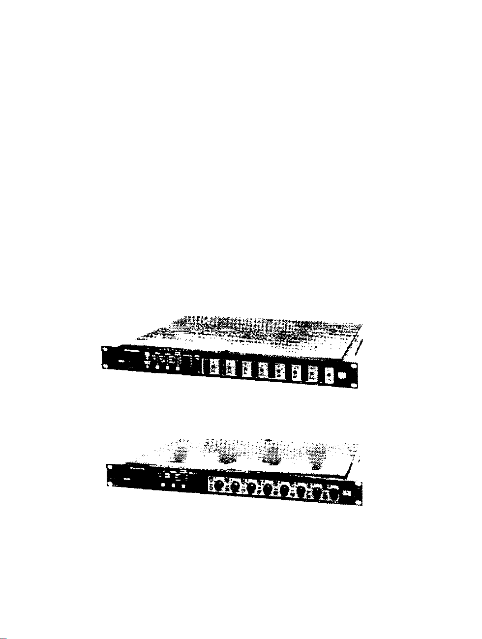
WZ-AD96
Front Panel
WZ-AD96M
Front Panel
12
Page 12

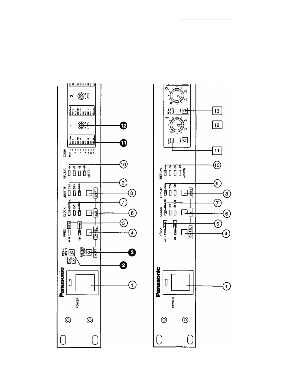
Chapter 2
MJiJOR CONTROLS and THEIR FUNCTIONS
Buttons sitk-printed half gray on the panel, here marked with < > brackets
are assigned double operation modes: normal mode and shift mode.
Indicators also have deferent function according to the operation modes.
During the < Shift Mode> all three Word Length Indicators light to identify
the operation mode. The <Shift Mode> operations are described after the
normal mode operations.
FRONT PANEL (NORMAL MODE)
© Power Switch and Power Indicator [POWER]
Turns on or off the power. The indicator lights while the power
power is on.
0 Peak Hold LED Button [PEAK HOLD] AD96 only
Peak hold time changes each time the button is pressed as follows.
0 second (LED: OFF) —> 2 seconds (LED: Green)
infinity(LED: Red) —> 0 second (LED: OFF)
0 Meter Mode Selection LED Button [METER ZOOM] AD96
only
Meter mode toggles between the normal display and zoomed display
each time the button is pressed.
Normal (LED: OFF) -> Zoom (LED: Green)
—> Normal (LED: OFF)
fool
PEAK
HOLD
METER
ZOOM
0
1 AJST 1
® Frequency Selection Button [FREQ]
When CLOCK is set to CRYSTAL the frequency is selected as
follows every time the button is pressed. The respective indicator
FREQ
44,1k (ZZ]|88Zk|
lights. 44.1k 48k —> 88.2k 96k —> 44.1k
When CLOCK is set to EXT and the unit follows 48k or 96k, the
frequency is selected as follows every time the button is pressed.
The respective indicator lights. 48k —> 96k —> 48k
48k tZDl 96k I
□
I CH-SEL I
When CLOCK is set to EXT and the unit follows 44.1k or 88.2k,
the frequency is selected as follows every time the button is
pressed. The respective indicator lights. 44.1k —> 88.2k —> 44.1k
® Frequency Selection Indicator [FREQ] [44,1k 48k 88.2k 96k ]
The upper LED lights when 44.1 kHz (Green) or 88.2 kHz (Red) is selected.
The lower LED lights when 48 kHz (Green) or 96 kHz (Red)is selected.
13
Page 13

Getting Started
(6) Clock Source Selection Button [CLOCK] clock
. .... . . .
This button toggles the clock source selection either external or
internal. If EXT is selected, this unit synchronizes to the wordclock □ error
signal supplied to the rear panel. The respective indicator lights.
© Clock Source Selection Indicator [CRYSTAL EKT ERROR]
Crystal: Lights in green when the unit operates with internal
clock.
EXT: Lights in green when the unit synchronizes to the external clock.
Error: Lights in red when an unlock or no input is detected in
the EXT setting, or for changing duration of internal frequency.
® Word Length Button [LENGTH]
For dither processing this button selects word length from among
24 bit, 20 bit or 16 bit, and the respective indicator lights.
□
l~C AL I
LENGTH
l—J 24bit
I
----
1 )6bil
□
® Word Length Indicator [24 20 16]
Selected word length is displayed; 24-bit, 20-bit or 16-bit.
@ Reference Level Indicator [REF LEVEL -20 -18 -16 -14]
These indicators display the reference level (Unit: dDFS) set by the
DIP switch on the rear panel.
® Level Meter [ PEAK -6 REF -24 -42 -58, PEAK -2 -4 -8 -10 -20 -30]
AD9^ Only
A 10-point bar graph meter is provided for each channel in the meter section.
The meters display levels in the normal or zoom mode set by the METER
MODE LED button. The normal scale is put right side the each meter while
the zoom scale is placed at the left side adjacent to the meter section.
I SHIFT I
REF LVL
CZ] -14
IZZI -16
I I -ia
CZ] -20
{dB FS)
aObit
In the normal mode the right side scale is referred.
PEAK, -6, (-12), REF, -24, (-30, -36), -42, (-48), -54
In the zoom mode the left side scale is referred.
PEAK, (-1), -2, (-3), -4, (-5), -6,-10, -20, -30
Input Level Trimmer [LEVEL] AD96 Only
Use a screw driver to adjust the level.
6ch A/D Converter WZ-AD96
Page 14

Chapter 2
. ,2
. .4
. .5
. 6
w.
0
[£] >
0
0
0
0 > 0 ■>
8ch A/D Conv«rter & Mic Pr« AMP WZ-AD96M
fm Level Indicator [PEAK/SIGNAL] AD^^M only
Signal levels are indicated as follows. Peak detection level is set by the
DIP switch on the rear panel.
Red; PEAK < Level
Amber: REF < Level < PEAK
Green: -38 dBFS < Level < REF
Off: Level < -38 dBFS
[T2] Input Level Trimmer [+4 -10 -60] AD96M only
Rotate the trimmer clockwise to boost or counter-clockwise to
reduce the gain.
|T^ Phantom LED Button [48V] AD96M only
Phantom power, 48 V is switched on or off. The LED lights while 48 V is
supplied to the analog input connector.
Caution! Phantom button can cause noise.
• Down the volume control of the amplifier to protect the speakers
from damage caused by switching noise before operating the phantom
button.
• Do not operate the phantom button for 30 seconds right after
turning on this unit to avoid switching noise.
. 7
■ .8
0 >
0
FRONT PANEL (SHIFT MODE)
Shift mode operations are briefly described below. Pressing the Word Length
<Shift> Button for 2 seconds or more will transfer the operation modes.
During the shift mode all three Word Length < Shift Mode > Indicators light
to identify the operation mode.
e <Level Adjust> LED Button [AJST] AD96 Only
Precise level adjustment is available. See page 23 for details.
(?) <Out Channel Selection> Button [CH-SEL]
This button selects output channels to the AES/EBU DIGITAL OUTPUT
connectors, 1-4 or 5-8. The respective indicator lights.
METER
ZOOM
I AJST
15
Page 15

Getting Started
Notes:
• Out channel selection is not available if 44.1 kHz or 48
kHz is selected for the reference source.
• When the DUAL AES/EBU card is installed in the unit, Out
channel selection is also available. Selecting 5-8 will result
in that contents of the channel 5-8 are supplied to both the
output channel 1-4 and 5-8 of the card.
(D < OUT Channel Selection> Indicator [44.1k 88.2k 48k
96k]
The upper LED (44.1 kHz, 88.2 kHz) lights in green when a set of channel 1-
4 is selected, or the lower LED (48 kHz, 96 kHz) lights when a set
of channel 5-8 is selected.
® <Calibration> Button [CAL]
Calibration to the clock synchronization is carried out manually by
pressing this button. Digital outputs are mute during calibration.
@ <Calibration> Indicator (CRYSTAL EXT ERROR]
Error indicator lights in red during calibration for about 1 second.
® <Shift Mode> Button [SHIFT]
Press this button to enter or to quit the shift mode.
FPEQ
M.lk [ZZll88-2kl
48k CDl 96k I
□
I CH-SEL 1
CLOG«
cm CRYSTAl
CD EXT
I—I ERROR
□
LENGTH
m] 24bit
nH
20M
□ 16W
® < Shift Mode > Indicator [24bit 20bit l6bit]
All three indicators light during the shift mode.
REAR PANEL
For AD96
® Analog Input connector [1-8 ANALOG INPUT -1-4 dB lOkfl (BAL)]
These XLR connectors accept analog signals supplied by external devices.
Input level is -1-4 dB for each channel. See the next page.
For AD96M
® Analog Input connector [1-8 ANALOG INPUT -60 dB to +4 dB lOkQ
(BAL)]
These XLR connectors accept analog signals supplied by external devices.
Input level is adjustable with a trimmer from -60 dB to -1-4 dB for each
channel. See the next page.
16
I SHIFT I
Page 16

-s
'S è
g g
53 >
"□ □
Ш (O
3 oi
Ф ^
O
D"
Û
■O
Ф
f\i
Page 17

Getting Started
(g) DIP Switch[l 2345678 ON OFF]
An 8-bit DIP switch is provided for settings . See page 21 for the ^
setting. ^ ®
ID I 't
rn I cn
fn~~l cy
mzi -
@ ADAT Output [ADAT OUT]
OFF ON
This optical connector supplies digital outputs for ADAT
@ Wordclock Input Connector [WORD CLOCK IN]
This BNC accepts the wordclock supplied by an external device. To
synchronize the internal clock to the wordclock in, select EXl' by
the CLOCK button, then select a frequency by the FREQ button.
@ Wordclock Output Connector [WORD CLOCK THRU]
This BNC supplies the wordclock looped through the WORD
CLOCK IN.
Sword aocr
@) Digital Output Connector [AESl AES2 AES3 AES4 AES/EBU DIGITAL
OUTPUT]
These XLR connectors supply AES/EBU digital outputs. Output channels for
Dual AES mode are selected from a set of 1, 2, 3 and 4, or 5, 6, 7 and 8 by
the FREQ/CH SEL button in the shift mode operation.
to .BKE ^ Qliia ^ EiE ^
--------
AESiBU DIGITAL OUTPUT
@ Grounding Terminal [SIGNAL GND]
Connect with other devices' GND to level the mutual ground potential if
required.
^ AC Inlet [AC IN]
Connect the supplied power code.
18
--------------------
SIGNAL
GND
AC IN
Page 18

Chapter 2___________________________________________________
Quick Start
Join the 6 steps below before you start digital recording.
1. Connect an analog source to the input channel on the rear panel.
2. Connect ADAT output or AES/EBU outputs to an external digital device
(for example a digital mixer, ADAT or DAT).
3. Turn on the AD converter, and confirm that POWER LED on the front
panel lights.
To reset to DEFAULT settings, turn on the AD converter while holding
down FREQ and CLOCK buttons at the same time.
4. Supply +4 dBu analog input, and adjust input trimmer so that REF LED
lights (lights in amber for AD96M).
The default setting of REF level is -20 dBFS.
5. Repeat step 4, level adjustment for the rest channels.
6. Play the connected analog source. 'I’hcn confirm that the level meter on
the AD converter swings, at the same time that the connected digital
device outputs analog signals or moves its meter.
See the next chapter, Adjustment and Setting, for REF level adjustment.
19
Page 19

Getting Started
Signal Fioxii
The chart shows how the analog inputs are converted to digital outputs.
The supplied analog signals are adjusted in the level while going through the
amplifier stage responding to the trimmer positions on the front panel.
The ADC transforms analog signal to digital data. The digitized audio data are
fed to word length, RliF level adjustment stages and then to meters.Word
length is set on the front panel while the REF level is selected on the rear
panel. Meter functions are controlled by buttons on the front panel and DIP
switches on the rear panel.
After passing the multiplex stage, the digital audio data are converted to the
selected format, then supplied to AESl-4 and ADAT connectors. Output
channel selection is made on the front panel in the shift mode operation.
On the bottom of the chart, the clock system is shown.
20
Page 20

Chapter 3
Adjustment and Sehing
DIP SmTCH Setting
On the Rear Panel an 8-bit DIP switch is provided. Following pages in this
chapter describe more information on each hmction. Default settings are
marked with +,
Switch # 7 and 8 select the reference level.
SW# Reference Level (in dBFS)
-20 -18
8
7
Off*
Off*
Off
On Off
Switch # 6 will function if internal setting is changed. See the next chapter.
SW# Wbrdclock output
Follows Sampling Follows AES
Frequency Output Rate
6 Off* On
Switch # 5 through 3 select the peak detection
level from among 8 options.
SW# Peak Detection Level (in dBFS)
-6.0
Off*
Off*
Off*
-5.0
Off
Off
On
SW# Peak Detection Level (in dBFS)
-2.0
On
Off
Off
-1.0
On
Off
On
-16 -14
On On
On
-4.0
Off
On
Off
-0.5
On
On
Off
-3.0
Off
On
On
0.0
On
On
On
m~> eg
m—1 1^
m—1 CD
fg~~i in
!□ r -i)-
fH~~l CM
(DZl ^
OFF ON
Reference Level
™ -14dBFS
-16dBFS
-ISdBFS
-20dBFS
WCK OUT Select
g Follows DIGITAL Oulpul
m Follows FREQ Select
Peak Detection Level
m B3
g O.OdBFS g -S.OdBFS
-O.SdBFS
m -1.0CJBFS
a
_______
-2.0dBFS
Future Use
AES/EBU 96kHz Tk Mode
U DualAES/EBU
^ Hi-Speed AES/EBU
-4,0dBFS
-S.OdBFS
-e.OdBFS
Switch # 2 does not function.
Switch # 1 selects the AES/EBU mode for 96 kHz operations.
SW# AES/EBU Tx Mode Selection
Hi-Speed Single Wire Dual mode
1 Off* On
21
Page 21

Adjustment & Setting
Preqse Level Adjustment for AD 96
1. Press <SHIFT> button for 2 seconds or more to enter SHIFI' operation
mode.
2. Press <Level Adjust> LED Button to enter the level adjustment mode.
The LED lights in red during the mode.
3. Supply +4 dBu signal from a generator to the input connector.
4. Rotate the trimmer with a screw driver so that both the PEAK and REF
LEDs light simultaneously.
LEDs will display how the trimmer adjustment proceeds as illustrated
below.
Up the Up the Matched Down the
trimmer ^ trimmer trimmer
t-1 fiCM
-2«
—
ncF
—^
--
mm ncp
---
t-1 PtAA
RET
^
---
^3 -42
B'l
L < -1 dB
5. Repeat step 3 and 4 for the rest channels.
6. Press <Level Adjust> LED Button to quit the level adjustment mode.
Or, press <SHIFT> button to quit the SHIFT mode operation.
-l£L<-0.1dB '0.1 < LS+0.1 dB +0.1<L<+1.0dB L>+1 dB
SI
Down the
trimmer
da
rTT-i U.
SI
22
Page 22

Chapter 3
Level Adjvstment for AD 96M
Factory setting is +4 dBu = -20 dBFS* when the trimmer is turned to the
end CCW position.
1. Connect a microphone to the input connector of the channel you will
adjust. Then speak to the mic.
2. Adjust the trimmer so that the LKD lights in amber (REF) when input is
average, and occasionally lights in red (PEAK).
3. Repeat above steps for the rest channels if necessary.
REF Level Setting
Select the Reference Level by setting DIP switch # 8 and 7 on the rear panel
to meet the connected device’s; from -20, -18 , -16 or -l4dBFS.
For example, when TASCAM DA88 is connected use -16 dBFS. [-16] of REF
LEVEL indicator lights on the front panel. This setting changes REF LEVI*L for
all 8 channels at once.
Level matching in digital audio is quite deferent from analog
world’s. Among analog devices it is simply accomplished just by
referring to +4dBu, even though individual head rooms are not
the same.
In digital world the gap of head room adversely affects on level matching,
resulting in clips and so forth. To easily eliminate the gap an idea of [REF
LEVEL] is introduced that indicates a minus digital scale from 0 dBFS (Digital
Full Scale). As listed below, individual equipment has its own [REF LliVEL]
equivalent to -1-4 dBu. Select an appropriate REF level by the DIP switch.
-14 dBFS: RAMSA WR-DA7, ’VAMAHA 03D, Lexicon PCM90/91
-16 dBFS: TASCAM DA88, AKAI DR8/DR16, Alesis ADAT XT (-15 dBFS)
-18 dBFS: Panasonic DAT SV-3900/4100/3700, Digidesign Pro Tools 888 I/O
-20 dBFS: RAMSA WR-DA7y Y\MAHA 02R, Others
WORD LENGTH Selection
Select a Word Length that meets to the connected device’s by pressing the
WORD LENGTH button on the front panel. If 16 or 20 bit is selected dither is
added to moderate distortions caused by discarded bits.
23
Page 23

Adjustment & Setting
TX Mode Selection
Data transmission formats are selected to meet the connected device’s and
system requirements.
• AES/EBU Output
Select an output mode by DIP switch #1 on the rear panel.
The high sampling signal has a double density information than
the normal. There are two transmission modes extended form the
normal AES/EBU Tx mode. The AD converter transmits either one
of extended modes.
Tx mode
AES/EBU(Normal) 2
Dual AES
(Dual Wire)
Hi-speed
(Single Wire)
• Dual AES Output Card
This is an option card to enable the AD converter supplying 8 channel
output in Dual AES/EBU mode.
• ADAX TDIF Output
An optical output : Dual track mode, 24 bit, 96 kHz, 4 channel is supplied.
• Output channel
Selecting CHl-4 or CH5-8 is implemented in SHIFT operation mode.
WoRDCLOCK Selection
Wordclock In setting is required.
• Wordclock In
The AD Converter examines input wordclcok frequency to have the internal
system clock synchronized to the input: 44,1, 88.2, 48 or 96 kHz. Contrary to
the Wordclock In, sampling frequency is selected manually on the front panel
by pressing the FREQ button.
Channel/Wire 7a: Rate
44.1/48 kHz
1
2
44.1/48 kHz MTRs
88.2/96 kHz Processors
Typical device
Cenex Recorder
Tc Electronics
y
24
Page 24

Peak Detection
The peak dots in the meters can be utilized in many ways; as a peak indicator
alerting that the level reaches just prior to the clip, or as a clip indicator;
respectively to the setting. Set the DIP switch #5-3 to -3 dB for use of a peak
meter, or to 0 dB for use of a clip meter. Furthermore 0 dB if the source is
percussive +2, 1 or 0.5 dB can be set to rust the peak detection.
AD Converter Caubration
The ambient temperature and AC voltage drift while using that may affects
on the conversion accuracy. The AD converter has automated calibration.
Manual calibration is also available to make the conversion optimum.
1. Press WORD LENGTH button for 2 seconds or more to enter SHIFT
operation mode.
2. Press CAL button. While the calibration is carried out, ERROR LED lights
and the outputs are muted.
Resume and Clear the Stored Data
• Resume
The AD converter retains following data while the power is off , and resumes
when turning on. Marked with * are default values that the AD converter
reloads when Memory Clear is implemented.
Peak Hold: OFF*/2 s/lnfinity
Meter Mode: Normal*/ Zoom
Clock Frequency: 48*/ 44.1/96/88.2 kHz
Clock Source; Internal*/External
Word Length; 24*/20/l6 bit
Out Channel Selection: 1-4*/5-8
• Memory Clear
To return the data back to the default, press the POWER switch while holding
down the [FREQ/CH SEL] and [CLOCK/CAL] button simultaneously.
25
Page 25

Self Diagnosis
The diagnosis program examines following items.
• Press the POWER switch while holding down the [FREQ/CH SEL] and
[WORD LENGTH/SHIFT] button simultaneously. The program starts, then
proceeds automatically to the end.
Backup Memory Check: If any error detected, the memory is
initialized to the default.
CPU-LSI Communication Check: If any error detected, all the LED
blinks on the front panel. To escape from error indication press the
[FREQ/CH SEL] and [WORD LENGTH/SHIFT] button simultaneously,
then contact the nearest service center.
LED Check: All the LED lights on the front panel.
Front Panel Button Check: Press the button one by one, the LED
responding to the button turns off.
DIP Switch Check:
AD96: The bar graph LEDs (10-point) on the 8th channel indicate the
switch status. The LED lights when the switch is On, or does not light
when it is Off. DIP switch #1 status is displayed in the PEAK position
and descending #2, 3, and so forth.
AD96M: PEAK/SIGNAL LEDs of eight channels indicate the switch
status. The LED lights when the switch is On, or does not light when
it is Off. DIP switch #1 status is displayed in the CH 1 position and
corresponding to #2, 3, and so forth.
•Turn off the AD converter when the diagnosis is completed.
Keylock
To protect the settings from mischief or mis-operation, this setting enables
the buttons on the panel to be inactive. Pressing buttons is ignored when this
is set to On except rotating trimmers and power On/Offs.
• To activate Key Lock turn on the POWER switch while holding down the
[CLOCK/CAL] and [WORD LENGTH/SHIFT] buttons simultaneously.
• To quit Key Lock press ]WORD LENGTH/SHIFT] button for 2 seconds or
more.
26
Page 26

Chapter 4
Internal Setting
&
Options
Warning!
Internal setting, option card installation, and rack mounting
should be made by qualified service personnel or system
installers only.
CAUTION:
TO REDUCE THE RISK OF ELECTRIC SHOCK,
DO NOT REMOVE COVER (OR BACK), NO
USER SERVICEABLE PARTS INDISE.
REFER SERVICING TO QUALIFIED SERVICE
PERSONNEL.
The lightning flash with arrowhead symbol,
within an equilateral triangle, is interned to
alert the user to the presence of uninsulated
"dangerous voltage" within the product’s
A
SA 1965
A
SA 1966
enclosure that may be of sufficient magnitude
to constitute a risk of electric shock to
persons.
The exclamation point within an equilateral
triangle is intended to alert the user to the
presence of important operating and
maintenance (servicing) instructions in the
literature accompanying the appliance.
27
Page 27

Internal Setting & Options
Internal setting
WoRDCLCOK-OuT Setting
In default setting the Worddcok THRU terminal supplies looped through
output of the Wordclock IN. Changing setting inside the unit enables the
wordclock terminal to supply internal clock to the connected device.
Wordclock Block Diagram
After this setting Wordclock IN constantly turns on the 150- termination
while the Wordclock THRU feeds internal clock.
Setting the DIP switch # 6 will select whether the unit follows the sampling
frequency or the clock selected .
Off: Wordclock THRU synchronizes to the sampling frequency selected
by the FREQ button.
On: Wordclock THRU synchronizes to the data transmission (output)
rate selected by the CLOCK button.
28
Page 28

Chapter 4
Options
Dual AES Output Card
This card supplies an 8-channel, 24 bit, 96 kHz signal to the connected
MTRs. For more information see instructions attached to the card.
\T
Dual AES Output Card WZ-AESAD
rfy ft OOOOOOOOOOOOO i /*1
oooooooooooo IflS)
CD
Pin Assignment
AES/EBS DIGITAL OUTPUT
□)
AES 8 Hot
GND
AES 7 Cold
AES 6 Hot
GND
AES 5 Cold
AES 4 Hoi
GND
AES 3 Cold
AES 2 Hot
GND
AES 1 Cold
Not used
-AES 8 Cold
-AES 7 Hot
-GND
-AES 6 Cold
-AES 5 Hot
-GND
-AES 4 Cold
-AES 3 Hot
-GND
-AES 2 Cold
-AES 1 Hot
-GND
Recommended Cable
Panasonic part # DA/OB'XLRM (DB-25 to 8 Male XLR,Length 3m), AD
Output cable is recommended.
29
Page 29

Internal Setting & Options
TDIF Output Card
This card converts an 8-channeI/24*bit/48kHz or 4-chan nei/24-bit/96kHz data
to TDIF format to connect the AD converter with an external DTRS, digital
tape recorder such as TASCAM DA88.
V
TDIF Output Card WZ-TDIAD
-TASCAM DIGITAL AUDIO l/F
o
CD
Pin Assignment
GND
GND
GND
GND
EO
FO 1
Not used
Not used
GND
GND
GND
GND
Recommended cable
For use with this card in one to one connection, Panasonic part # DA/DB-
TDIF (DB25 to DB25(TDIF), Length 3m) is recommended. PW-88D (Im) or
PW-88DL (5m) supplied by TASCAM are also recommended.
Other than one to one connection, you may need a Y cable shown in the
next page for use with this card, a DTR and a DA converter at the same time.
30
Page 30

Chapter 4
DB25Y Cable
To connect the AD converter (TDIF Card installed) with the DA converter
WZ-DA96 and a DTRS device (DA88 and so forth) you need to build a Y cable
shown below.
MOUNTING IN THE RACK
The AD converter is installed in an EIA 19” rack as follows. .
• Install the AD converter in the rack by using four screws (standard
accessory).
Caution:
• Before mounting make sure that the rack mounting brackets on both
sides the unit are fixed with screws.
• Do not block the ventilation opening or slots on the cover to prevent
the appliance fi-om overheating. Always keep the temperature in the rack
within 45®C (113*^19.
• Secure the rear of the appliance to the rack by using additional
mounting brackets (procured locally) if the rack is subject to vibrations.
31
Page 31

Connecting the System
Connecting the System
System examples are shown in following pages.
Connection - 1: Connecting with the DA7 Digital Mixer
Connection - 2: Connecting with the ADAT & BRC
Connection - 3: Connecting with TDRS
Connection - 4: Connecting with Pro Tools
Connecting mn the DA 7 Digital Mixer (Connection 1)
Wordclock master ; WR-DA7, AD Converter: To sync to DA7
• Connection
1. Connect between Wbrdclock-Out (75n=ON) on the DA7 and Wordclock-In
on the AD converter with a BNC cable.
2. Connect between Wbrdclock-Out on the AD converter #1 and WordclockIn on the converter #2 with a BNC cable.
3. Connect between ADAT-Outs on the AD converters and ADAT-1 ns on the
WR'ADAT cards installed in the DA7 with two optical cables.
4. Connect between ADAT-Out on the ADAT card #3 and DIGITALT-In on the
ADAT with an optical cable.
5. Connect between ADAT- IN on the ADAT card #3 and DIGITALT-OUT on
the ADAT with an optical cable.
6. Connect between the DA7 and the DAT: Rec Out to AES/EBU In and 2TR A
In to DAT Out with two XLR cables.
• Setting
1. On the DA7, set the SOURCE SELECT to “INT 44.1 K” or “INT 48 K”, and
set the SLOT 3 of the DIGITAL INPUT SELECT to INPUT 9-14 and 15/16, in
the [D-I/0> INPUT SET] window.
2. Set SLOT 3 to INS in the |D-I/0>T0 SLOT] window to function SLOT 3 in
send-return mode.
3. On the front panel of the AD converter, select “EXT” by pressing the
CLOCK button to be slaved to DA7’s wordclock. Set both the DIP switch
#7 and 8 to ON to meet the REF level of -l4dBFS.
32
Page 32

Chapter 5
4. On the ADAT, select “DIG” by pressing the CLOCK SELECT switch to sync
to the digital input.
Legend
clcx:k: -
AUDIO: -
Key Board
WZ-AD96M Setting
• CLOCK:EXT
•REF LEVEL: -14dBFS
• WORDCLOCK OUT: THRU
WCK OUT (7^1-ONl
loui E
ADAT
#2 #3
«1
WR- WR-
WR-
ADATADAT
IcSlTEI®^'
DDeeeBBseeGeGQBSBBBQE
1 WORD CLOcTmAS^^I WR-DA7
ADAT Setting
• CLOCK SEUOIGl
•INPUTSEL: DIGITAL
D □ a □ □ D
* noono n Qi ^
SP
I
ft«:
WR-DA7 Setting
[D-l/0>INPUTSET]
• SOURCE SEL: INT 44.1k/48k
• DIGITAL INPUT SEL: SLOT3-INPUT9-16
ID-1/0>T0 SLOT]
• SLOTS: INS
Connection-1
33
Page 33

Connecting the System
Connecting with the ADAT & BRC (Connection 2)
Wordctock master: WZ-AD96/96M AO Converter
• Connection
1. Connect between Wbrdclock-Out on the AD converter and WCK In on the
DA converter with a BNC cable. In addition connect between WCK THRU
on the DA converter and 48 kHz In on the BRC with a BNC cable. Note
that inside the AD converter both CN907 and 908 jumpers are set to
“OUT” positions.
2. Connect between ADAT Out on the AD converter and Digital-In on the
ADAT with an optical cable to transmit 1-8 channel digital audio data.
3. Connect between DIGITAL Out on the ADAT and ADAT-In on the DA
converter with an optical cable to monitor the sound.
4. Connect between Remote Out to ADAT on the BRC and SYNC-In on the
ADAT .with a SYNC cable to control ADAT remotely and to take
synchronization.
• Setting
1. On the AD converter, select “CRYSTAL” by pressing the CLOCK button to
let it work as the wordclock master. In addition select a sampling
frequency by pressing the FREQ button. Note that if 88.2 or 96 kHz is
selected , move the DIP switch #6 to On to keep sending 44.1 or 48 kHz
wordclock to the BRC and ADAT.
2. Set the DIP switch on the AD converter #7 to Off and #8 to On to meet
the REF level to -16 dBFS. See “REF Level Setting”.
3. On the AD converter, select output channels: 1-4 or 5*8: after entering the
SHIFT operation mode if 88.2 or 96 kHz is used. The selected channel
outputs will be recorded on the ADAT's tracks: output channels “1, 2, 3
and 4” or “5, 6, 7 and 8” will be recorded onto track 1/2, 3/4, 5/6 and 7/8
respectively.
(1) To enter the SHIFT operation mode press the WORD LENGTH button
for 2 second or more.
(2) Press the FREQ button to select output channels. The FREQ LEDs
indicate the selection.
CH 1-4; The FREQ LED 44.1k/88.2k lights.
CH 5-8: The FREQ LED 48k/96k lights.
4. On the BRC, select “48 k Input” by pressing the EXT SYNC switch to sync
to the wordclock.
34
Page 34

Chapter 5
5. On the ADAT’s front panel, press the DIGITAL IN switch to receive digital
audio input.
Legend
CLOCK: — -►
AUDIO:
--------
►
Connection-2
35
Page 35

Connecting the System
Connecting with TDRS (Connections)
Wordclock master: WZ-AD96/96M AD Converter
• Connection
1. Install the TDIF card, an option to the AD converter, into the rear slot.
See instructions attached to the card for more details.
2. Connect between Wordclock-Out on the AD converter and WCK IN on the
DA converter with a BNC cable. In addition connect WCK THRU on the DA
converter and WORD SYNC In on the DA88 converter with a BNC cable.
Note that inside the AD converter both CN907 and 908 jumpers are set to
“OUT” positions.
3. Connect TDIF Out on the AD converter and TDIF In on the DA88 with a
DB25 Y cable as illustrated. In addition connect one end of the DB25 Y
cable to the TDIF In on the DA converter to monitor the sound. See page
40 for detailed information on DB25 Y cable.
• Setting
1. On the AD converter, select “CRYSTAL” by pressing the CLOCK button,
then select a sampling rate by pressing the FREQ button. Note that if 88.2
or 96 kHz is selected , move the DIP switch #6 to On to keep sending
44.1 or 48 kHz wordclock to the DA88.
2. Set the DIP switch on the AD converter #7 to Off and #8 to On to meet
the REF level to -16 dBFS. See “REF Level Setting”.
3. On the DA88, select “WORD” by pressing the CLOCK switch to let it sync
to the wordclock.
4. On the AD converter, select output channels: 1-4 or 5-8; after entering the
SHIFT operation mode if 88.2 or 96 kHz is used. The selected channel
outputs will be recorded on the DA88’s tracks: output channels “1, 2, 3
and 4” or “5, 6, 7 and 8” will be recorded onto track 1/2, 3/4, 5/6 and 7/8
respectively.
(1) To enter the SHIFT operation mode press the WORD LENGTH button
for 2 second or more.
(2) Press the FREQ button to select output channels. The FREQ LEDs
indicate the selection.
CH 1-4: The FREQ LED 44.1k/88.2k lights.
CH 5-8: The FREQ LED 48k/96k lights.
5. On the DA88’s front panel, press the DIGITAL IN switch to receive digital
audio input.
36
Page 36

Chapter 5
Legend
CLOCK;
AUDIO:
-----
-------
Connection-3
37
Page 37

Connecting the System
Connecting with Pro Tools (Connection 4)
Wordclock master: Pro Tools 888 I/O
• Connection
1. Connect SLAVE CLOCK OUT on the 888 I/O #1 and SLAVE CLOCK IN on
the 888 I/O #2 with a BNC cable. Then connect between #2 and #3 in
the same way as #1 and #2.
2. Connect SLAVE CLOCK OUT on the 888 I/O #3 to WCK In on the DA
converter with a BNC cable.
3. Connect WCK Out on the DA converter and WCK In on the AD converter
#1 with a BNC cable. Then, connect between Wordclock-Out on the AD
converter #1 and Wordclock-In on the AD converter #2 with a BNC cable.
In the same manner connect the AD converter #2, #3 and the DA
converter with BNC cables.
4. Connect AES/EBU Out on the AD converter #1 and AES/EBU In on the 888
I/O #1 with XLR cables. For #2 and #3 connect in the same manner.
5. Connect between the AES/EBU Out on the 888 I/O #1 and AES/EBU In on
the DA converter with XLR cables to monitor the sound.
Setting
1. Set SYNC MODE to “INTERNAL”, and select SAMPLE RATE from 44.1k or
48k on the 888 I/O #1.
2. Set Channel 1-8 INPUT to “DIGITAL”, and 1-2 FORMAT to “AES/EBU”on the
888 I/O #1-3.
3. On the AD converter select “EXT” by pressing the CLOCK button, and set
the DIP switch #7 to On and #8 to Off to meet the REF level to -18 dBFS.
See “REF Level Setting”.
38
Page 38

Chapter 5
Legend
CLOCK; - - -►
AUDIO: *
Key Board
; WZ-AD96/AD96M Setting!
; • CLOCK: EXT ;
I'REFLEVELi-ISdBFS •
; • WORD CLOCK-OUT; THRU ■
I WQRO CLOCK K WZ- DA96
Otn - ^
WZ-DA96 Setting
•CLOCK: EXT
®
1©
SPL SP LC
©
i Pro Tools 888 I/O Setting
: • SYNC MODE: INTERNAL (#1)
1 • SAMPLE RATE: 44.1 kHz/48 kHz (#1)
i • INPUT: DIGITAL
;*1-2F0RMAT: AES/EBU
№5DO?f
’r
X
SOPER CLOCK (25«X) f
s r \1==i
^E'oaQtS
^“1"
MX
i)
|n
H
SPC
SP SUB
Connection-4
© ©
SP RC
SPR
39
Page 39

Chapter 6
Technical Specifications
General
Power requirement
Power consumption
Dimensions (mm)
(inch)
Weight
Analog Input
Analog In
Impedance
Maximum Input Level
Trim Level
Input Gain Level
THD + N
(+4 dBu, 20 Hz-20 kHz) 0.003%, 90.5 dB
(+24 dBu, 20 Hz-20 kHz)0.0003%, 110.5 dB
Dynamic Range
E.I.N
Group Delay (at 48 kHz)
Channel Separation
Frequency Response
(+4 dBu, 20 Hz-20 kHz)
C.M.R.R (at 1 kHZ)
Sampling Rate
Resolution
WZ-AD96 W2-AD96M
AC 120 V 60 H2 AC 120 V 60 Hz
18 W 19 W
480(W)x44(H)x350(D) 480(W)x44(H)x350(D)
16-9/16(W)x1-3/4(H)x13*3/4(D)
3 Kg(ll lbs)
XLR X 8
10 kil Balanced
+ 30 dBu (-6 dB trim)
+4 dBu±6 dB
118 dB
38.7/Fs sec (0.806 ms)
114 dB
+0.0 dB -0.2 dB
> 70 dB
44.1 kHz-96 kHz
24 bit
16-9/16(W)x1-3/4(H)x13-3/4(D)
5 kg(ll lbs)
XLR X 8
10 kQ Balanced
+ 24 dBu
-60 dBu to +4 dBu
0.003%, 90.5 dB
0.0004%, 110.5 dB
117 dB
-128 dB
38.7/Fs sec (0.806 ms)
113 dB
+0.0 dB -0.2 dB
> 80 dB
44.1 kHz - 96 kHz
24 bit
Digital In & Our
Meter
Type
Accuracy
Peak-Hold
Mode
Bargraph
10-point
±0.05 dB
2 s/ oo / Off
Normal/Zoom/Adjust
Signal/Reference/Peak
1- point, 3*color
±0.05 dB
41
Page 40

Digital Jn & Out
Technical Specifications
Wordclock In
Wordclock Out
ADAT Out
Format
AFS/EBU Output
Format
Dither
Standard Accessories
BNC X 1, 75 n auto-termination
BNC X 1, Looped-thru or Internal Out
Optical X 1
24bit, Normal/96k Dual Channel
XLRx 4
24bitj NormaI/96k Hi-Speed Single Wire/96k Dual wire
l6bit, 20bit
Power Code
Screw
Rubber Foot
Optional Accessories
x4 (M5xl0) For rack mounting
5
Dual AES 8ch Output Card (WZ-AESAD)
Output Connector
Format
Signal Level
Channel Mode
DB25
AES/EBU (24 bit A1’S3-1992)
RS-422
8 ch, 24-bit, 44.1/48 kFlz, Normal AES
8 ch, 24-bit, 88.2/96 kHz, Hi-Speed AES
8 ch, 24-bit, 88.2/96 kHz, Dual AES
Dimensions
108(W) x 37(H) x 62(D) mm
4-l/4(W) X l-7/l6(H) X 2-7/l6(D) inch
Weight
230 g (0.51 lbs)
TDIF Output Card (WZ-TDIAD)
Output Connector
Format
Signal Level
Channel Mode
DB 25
TDIF-1 (24bit Normal/96k Dual Channel)
CMOS Level
8 ch, 24-bit, 44.1/48 kHz, Normal
4 ch, 24-bit, 88.2/96 kHz, Dual Channel
Dimensions
108(W) X 37(H) X 62(D) mm
4-l/4(W) X l-7/l6(H) X 2-7/l6(D) inch
Weight
____________
230 g (0.51 lbs)
42
__________________________
Page 41

Chapter 6
Level Diagram
W2-AD96
WZ-AD96M
INPUT
(dBu)
DIGtTAL
OUTPUT
■90
■100 U
'110 -
*120 -
43
Page 42

Block Diagram
Technical Specifications
44
Page 43

Chapter 6
Dimensions
W2-AD96
WZ-AD96M
45
Page 44

High Sampling Digital Formot
High Sampling Digital Format
This section details the channel relationship between analog inputs and
digital outputs depending on the format.
AESIEBU Outputs On the Rear Panel
Normal AES/EBU Mode
Word length=24 bit, Sampling rate=
Analog Input CH #
1 & 2
3 & 4
5 & 6
7 & 8
Hi-Speed AES/EBU Mode
Word length=24 bit, Sampling rate=
Analog Input CH #
1 & 2
3 & 4
5 & 6
7 & 8
=44.1/48 kHz, Tx rate=44.1/48 kHz
Digital Output
AES 1
AES 2
AES 3
AES 4
=88.2/96 kHz, Txrate=88.2/96 kHz
Digital Output
AES 1
AES 2
AES 3
AES 4
Dual AES/EBU Mode
Word lcngth = 24 bit, Sampling rate=
Analog Input CH #
1 or 5
2 or 6
3 or 7
4 or 8
Dual AES/EBU Output Card (Option)
Hi-Speed AES/EBU Mode
Word length=24 bit, Sampling rate==88.2/96 kHz, Tx rate=88.2/96 kHz
=88.2/96 kHz , Tx rate=44.1/48 kHz
Digital Output
AES 1
AES 2
AES 3
AES 4
46
Page 45

Appendix
Analog Input CH #
1 & 2 AES 1
3 & 4
5 & 6
7 & 8 AES 4
1 & 2
3 & 4
5 & 6 AES 7
7& 8 AES 8
Dual AES/EBU Mode
Word length=24 bit, Sampling rate=88.2/96 kHz, Tx rate=44.1/48 kHz
Analog Input CH # Digital Output
1 AES 1
2 AES 2
3 AES 3
4 AES 4
5 AES 5
6 AES 6
7 AES 7
8 AES 8
Digital Output
AES 2
AES 3
AES 5
AES 6
ADAT Output on the Rear Panel
ADAT Normal Mode
1 = 24 bit, Sampling rate=44.
Analog Input CH #
1 TRl
2
3 TR3
4
5
6
7
8
1/48 kHz
Digital Output
TR2
TR4
TR5
TR6
TR7
TR8
47
Page 46

ADAT Dual Track Mode
Word length=24 bit, Sampling rate=:88.2,^6 kHz
Analog Input CH # Digital Output
1 or 5
1 or 5
2 or 6
2 or 6 TR4
3 or 7
3or 7
4 or 8
4 or 8 TR8
TDIF Output Card (Option)
Normal TDIF Mode
Word length=24 bit, Sampling rate= 44.1/48 kHz
Analog Input CH # Digital Output
1
2 TR2
3 TR3
4 TR4
5 TR5
6 TR6
7 TR7
8 TR8
TDIF Dual Track Mode
Word length=24 bit, Sampling rate=
Analog Input CH #
1 or 5
1 or 5
2 or 6
2 or 6 TR4
3 or 7 TR5
3 or 7
4 or 8 TR7
4 or 8 TR8
High Sampling Digitai Format
TRl
TR2
TR3
TR5
TR6
TR7
TRl
:88.2/96 kHz
Digital Output
TRl
TR2
TR3
TR6
48
Page 47

Appendix
_________________________
Sub-Code IN AES¡EBU Output
The AD Converter uses following sub-codes.
Bit position
Byte #0
Byte#l
7 6 5 4 3 2 1 0
— 000: Emphasis not specified
— 0: Lock
00:88.2/96 kHz
01:44.1 kHz
10: 48 kHz
11 : Not used
I— 0000: Default
Else : Not used
Else; Not used
Else : Not used
'— 1: Professional
Else: Not used
— 0: Audio
Else: Not used
- 0000: Normal, 96 kHz, Hi-speed
1000:96 kHz Dual AES L channel
1001:96 kHz Dual AES R channel
Else: Not used
Byte #2
Byte #3
Byte #4
6 5 4 3 2 1 0
i— 4
000: Default
— 00: Default
7 6 5 4 3 2 1
- 0: Default
Else: Not used
Else: Not used
-0000: 44.1/48 kHz
0100: 96 kHz
1100:192 kHz
0101:88.2 kHz
1101; 176.4 kHz
Else: Not used
Else: Not used
001: Bit number extension upto 24
Else; Not used
■ 000: Default
Else: Not used
L—— 00: Default
Else: Not used
— 0: Default
Else: Not used
49
Page 48

High Sampling Digital Format
Bit position
7 6 5 4 3 2 1
1
0
All 0: Detault
Else : Not used
Byte #6 - 9
Byte #18-21
Byte #22
7
7
7 6 543
7 6 5 4 3 2 1
7
4 3 2 1
6 5
6 5
6 5
----0: Byte #18-21 credible
Else: Not used
--------
4 3 2 1
n ^
--------------------
2 1
1-----------------------
1
4 3 2
——0: Byte #0-5 credible
Else: Not used
■0: Byte #6-13 credible
Else: Not used
0: Byte #14-20 credible
Else: Not used
0
■—
0
0
0
1 0
All 0: Detault
Else : Not used
All 0; Default
Else: Not used
All 0: Detault
Else: Not used
All 0: Default
Else: Not used
■ 0000: Default
Else: Not used
SO
Byte #23 2 1
■ CRC data byte
Page 49

Page 50

Panasonic Broadcast & Television Systems Compariy
Professional Audio Division
3330 Cahuenga Boulevard. Los Angeles, CA 90068 Telephone (323) 436-3500
N1299-0
© Matsushita Communication Industrial Co., Ltd. 1999
YWA8QA5356AN
Printed in Japan
 Loading...