

Page 1
WX-CC2010
TRANSCEIVER
MONITOR
POWER
VEHICLE
PRESENT
A
B
WX-CT2020
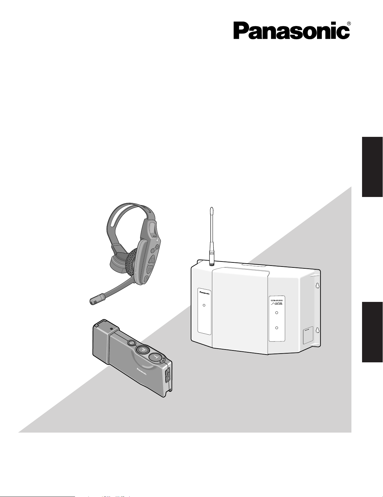
Wireless Communication System
Center Module
Operating Instructions
Model No. WX-CC2010 Series
Digital Technology
ENGLISH
Before attempting to connect or operate this product,
please read these instructions carefully and save this manual for future use.
FRANÇAIS
Page 2
Ni-MH
L i-ion
ENGLISH VERSION
FEDERAL COMMUNICATIONS COMMISSION INTERFERENCE STATEMENT
This equipment has been tested and found to comply with the limits for a Class B digital device, pursuant to Part 15 of the FCC Rules.
These limits are designed to provide reasonable protection against harmful interference in a residential installation. This equipment generates, uses and can radiate radio frequency energy and, if not installed and used in accordance with the instructions, may cause harmful
interference to radio communications. However, there is no guarantee that interference will not occur in a particular installation. If this equipment does cause harmful interference to radio or television reception, which can be determined by turning the equipment off and on, the
user is encouraged to try to correct the interference by one of the following measures:
• Reorient or relocate the receiving antenna.
• Increase the separation between the equipment and receiver.
• Connect the equipment into an outlet on a circuit different from that to which the receiver is connected.
• Consult the dealer or an experienced radio/TV technician for help.
FCC Warning: This transmitter must not be co-located or operated in conjunction with any other antenna or transmitter.
FCC Warning: This equipment complies with FCC radiation exposure limits set forth for uncontrolled equipment and meets the FCC radio
frequency (RF) Exposure Guidelines in Supplement C to OET65. This equipment should be installed and operated with at least 20 cm and
more between the radiator and person's body (excluding extremities: hands, wrists, feet and legs).
FCC Warning: To assure continued FCC emission limit compliance, use only the provided power supply cord and shielded interface cable
when connecting this device to the computer. Also, any unauthorized changes or modifications to this
equipment would void the user's authority to operate this device.
This device complies with Part 15 of the FCC Rules. Operation is subject to the following two conditions: (1) This device may not cause
harmful interference, and (2) this device must accept any interference received, including interference that
may cause undesired operation.
DoC Responsible Party: Panasonic Corporation of North America
Technical Support Party: Panasonic Consumer Electronics Company
Technical Support Tel No.: 886-472-6767
One Panasonic Way, Secaucus, NJ 07094
1707 N. Randall Rd., Elgin IL. 60123
CAUTION
RISK OF ELECTRIC SHOCK
DO NOT OPEN
CAUTION: TO REDUCE THE RISK OF ELECTRIC SHOCK,
DO NOT REMOVE COVER (OR BACK).
NO USER-SERVICEABLE PARTS INSIDE.
REFER SERVICING TO QUALIFIED SERVICE PERSONNEL.
The lightning flash with arrowhead symbol,
within an equilateral triangle, is intended to
alert the user to the presence of uninsulated
"dangerous voltage" within the product's enclosure that may be of sufficient magnitude to
SA 1965
SA 1966
ATTENTION:
constitute a risk of electric shock to persons.
The exclamation point within an equilateral triangle is intended to alert the user to the presence of important operating and maintenance
(servicing) instructions in the literature accompanying the appliance.
A battery that is recyclable powers the product you
have purchased. Please call 1-800-8-BATTERY for
information on how to recycle this battery.
A lithium-ion battery that is recyclable powers the product you have purchased. Please call 1-800-8-BATTERY for information on how to recycle this battery.
CAUTION
It is a violation of Federal Law to begin operating this system prior
to obtaining an FCC Radio License. The FCC ID number for this
radio equipment is listed below.
FCC ID: ACJ9TAWX-CC2010Z
RSS-210
This device has been designed to operate with an antenna having a
maximum gain of –3 dB. Antenna having a higher gain is strictly
prohibited per regulations of Industry Canada.
The required antenna impedance is 50 ohms.
To reduce potential radio interference to other users, the antenna
type and its gain should be so chosen that the equivalent isotropically radiated power (EIRP) is not more than that required for successful communication.
Danger of explosion if battery is incorrectly replaced.
Replace only with the same or equivalent type.
The serial number of this product may be found in the battery compartment of the unit.
You should note the serial number of this unit in the space
provided and retain this book as a permanent record of your
purchase to aid identification in the event of theft.
Model No.
Serial No.
WARNING:
To prevent fire or electric shock hazard, do not expose this
appliance to rain or moisture. The apparatus shall not be
exposed to dripping or splashing and that no objects filled with
liquids, such as vases, shall be placed on the apparatus.
2
Page 3

IMPORTANT SAFETY INSTRUCTIONS
1) Read these instructions.
2) Keep these instructions.
3) Heed all warnings.
4) Follow all instructions.
5) Do not use this apparatus near water.
6) Clean only with dry cloth.
7) Do not block any ventilation openings. Install in accordance with the manufacturer's instructions.
8) Do not use near any heat sources such as radiators, heat registers, stoves, or other apparatus (including amplifiers) that
produce heat.
9) Do not defeat the safety purpose of the polarized or grounding-type plug. A polarized plug has two blades with one wider
than the other. A grounding-type plug has two blades and a third grounding prong. The wide blade or the third prong are
provided for your safety. If the provided plug does not fit into your outlet, consult an electrician for replacement of the
obsolete outlet.
10) Protect the power cord from being walked on or pinched particularly at plugs, convenience receptacles and the points
where they exit from the apparatus.
11) Only use attachments/accessories specified by the manufacturer.
12) Use only with the cart, stand, tripod, bracket, or table specified by the manufacturer, or sold with the apparatus. When a
cart is used, use caution when moving the cart/apparatus combination to avoid injury from tip-overs.
S3125A
13) Unplug this apparatus during lightning storms or when unused for long periods of time.
14) Refer all servicing to qualified service personnel. Servicing is required when the apparatus has been damaged in any way,
such as power-supply cord or plug is damaged, liquid has been spilled or objects fallen into the apparatus, the apparatus
has been exposed to rain or moisture, does not operate normally, or has been dropped.
ENGLISH
3
Page 4

CONTENTS
IMPORTANT SAFETY INSTRUCTIONS ...................................................................................................... 3
PREFACE..................................................................................................................................................... 5
PRECAUTIONS............................................................................................................................................ 6
PANASONIC WX-CC2010 SERIES SYSTEM PARTS AND ACCESSORIES ................................................ 7
MAJOR OPERATING CONTROLS AND THEIR FUNCTIONS ..................................................................... 8
■ WX-CC2010 Center Module ................................................................................................................. 8
■ WX-C516 Power Transformer ............................................................................................................... 12
■ WX-C550 Speaker Microphone ............................................................................................................ 12
OPERATING PROCEDURES....................................................................................................................... 13
COMPATIBILITY ......................................................................................................................................... 13
TROUBLESHOOTING ................................................................................................................................. 13
STANDARD ACCESSORIES ....................................................................................................................... 13
SPECIFICATIONS........................................................................................................................................ 14
4
Page 5

PREFACE
Panasonic WX-CC2010 Center Module is designed for
Panasonic Wireless Communication System, which is used
with drive-through menu boards, etc. The system operates
on UHF frequencies, and offers multi-channel flexibility
making use of the PLL (Phase Locked Loop) technology.
FEATURES
•A remote speaker can be added to the system.
• The WX-CT2020 Order Taker Unit and WX-CH2050A
All-in-One Headset are designed to facilitate the battery installation.
New Functions of the WX-CC2010
(New Technological Features)
•New DNR (Digital Noise Reduction)
The New DNR function provides sound quality without
noise that accompanies digital processing. (WXCC2010 Center Module has the sound quality of customer's voice which has been improved than that of
WX-C1011 Center Module.)
• Talkback Echo Elimination
Digital delay processing eliminates talkback echo from
the order taker unit.
• TBC (Talkback Automatic Level Control)
Only human voice is identified in a mixed input of customer's voice and noise from the menuboard microphone. Then, the volume of customer's voice is compared with the talk volume of the order taker unit, and
the talkback volume level is automatically controlled.
5
Page 6

PRECAUTIONS
This center module is a sensitive device and should be
regarded as such. If handled carelessly, the hazard of electric shock may exist.
In order to utilize the instrument to its fullest potential,
please consider the following precautions.
1. Handle the equipment with care. This equipment contains sensitive components that can be damaged by
improper handling or storage.
2. Refer any servicing to qualified service personnel. Do
not attempt to disassemble the center module, order
taker unit or other units. In order to prevent electrical
shock, do not remove screws or covers. There are no
user-serviceable parts inside.
3. Use a dry cloth to clean the center module, order taker
unit or other units if soiled or dirty. If necessary, a mild
detergent may be used.
4. Take immediate action if the center module or order
taker unit becomes wet. Turn the power off and have
the unit examined by qualified service personnel. Do
not expose the center module or order taker unit to rain
or moisture, or attempt to operate the equipment in wet
areas. Do not operate the equipment if it is wet.
7. Replace a missing microphone cover and ear speaker
cover of the headset with a new one to prevent distortion or loss of audio.
8. Repair or replace any defective components.
9. Turn off the order taker unit when not in use, in order to
save the battery life.
10. When the power indicator lights up in red and a pulsing
beep tone is heard in the headset, charge battery to
the order taker unit (if using WX-CT2020 in combination
with WX-C1027A) or all-in-one headset (if using WXCH2050A).
11. Clean the battery charger of the order taker unit or allin-one headset in accordance with manufacturer
instructions at least once a month. (Refer to the operating instructions of the battery charger.)
12. Perform regular preventive maintenance by testing
accessories (headset and batteries, etc.)
5. Follow normal safety precautions to avoid personal
injury.
6. Properly store the order taker unit (WITH HEADSET
PLUGGED IN) in the order taker unit case to prevent
damage to equipment.
6
Page 7

PANASONIC WX-CC2010 SERIES SYSTEM PARTS AND ACCESSORIES
A
B
WX-CT2020
WX-CC2010
T
R
A
N
S
C
E
I
V
E
R
M
O
N
I
T
O
R
POWER
VEHICLE
PRESENT
C
o
n
d
itio
n
in
g
Condition
C
h
arg
in
g
R
e
a
d
y
F
u
ll
C
o
n
d
itio
n
in
g
C
o
n
d
i
t
i
o
n
C
h
a
rg
in
g
R
e
a
d
y
F
u
ll
Conditioning
C
o
n
d
it
io
n
Charging
R
e
a
d
y
F
u
ll
Conditioning
C
on
ditio
n
Charging
Ready
Full
Note: Illustrations may differ from actual products.
■ Center Module
WX-CC2010
■ Headset
WX-C1027A
■ All-in-One Headset
WX-CH2050A
■ Speaker Microphone
WX-C550
■ Order Taker Unit
WX-CT2020
■ Vehicle Detector 917-1
(Locally Procured)
■ Speaker/Loop Cable Kit
WX-C688
■ Rechargeable Battery
For WX-CH2050A: 2050BAT or 2051BAT
For WX-CT2020: 2020BAT
■ Power Transformer
WX-C516
■ Battery Charger
For WX-CH2050A: 2050CH
For WX-CT2020: 2020CH
■ Order Taker Unit Case
WX-CT2022
7
Page 8

MAJOR OPERATING CONTROLS AND THEIR FUNCTIONS
W
X-CC2010
TR
A
N
SC
E
IVE
R
M
O
N
ITO
R
ULTRAPEX II
POWER
VEHICLE
PRESENT
DNR
A
B
POWER
VEHICLE
PRESENT
o
y
!0 !1 !2 !3 !4
!5
u
i
OFF
OFF
OFF
OFF
LINE
OFF
ON
ON
ON
ON
G/MIC
ON
REMOTE
AUX IN SEL
TALK MONITOR
AUX IN
TALK
PAGE
BEEP
A
OFF
USA
OFF
OFF
OFF
OFF
OFF
B
ON
CND
ON
ON
ON
ON
ON
CHANNEL
CONTINUES
USA/CANADA
T/B
LEVEL
DNR
EFFECT
TBC1
TBC2
DNR1
DNR2
DNR3
VEHICLE DETECTOR
CH SELECT
NORMAL
OFF
OVERRIDE ON
1
2
3
4
5
6
7
8
POWER
ON
OFF
CAUTION
USE WITH SPECIFIED
EQUIPMENT SEE ITS MANUAL
BEFORE CONNECTING
CIRCUT
PROTECTOR
!6 !7 !8 !9 @0 @1 @2 @3 @4
■ WX-CC2010 Center Module
8
OUTPUT
MENU SP REMOTE SP
010 010
MENU MIC
010 010010
MENU BOARD
MICSP 8 ‰
HHCC
GND
INPUT BEEP
REMOTE
NC NC
SPEAKER
GND
H
AUX IN
DDT
INPUT
CONTROL
AUX
O / T
TALK LOCK
DAY
RELEASE
NIGHT
G/MIC
PTT
HC
IN
COMOUT GND
V/DET DDT
IN
COM
TRANSFORMER
AC
12V
LOAD
IN
Page 9

Notes:
Setting
Talkback
Level
TBC1
TBC2
TBC1
TBC2
TBC1
TBC2
TBC1
TBC2
Normally set to this position.
Talkback level set to 50 %.
Talkback level set to 35 %.
Talkback level set to 25 %.
Remarks
–6 dB
–9 dB
–12 dB
–Talkback is off.
Setting
Noise
Reduction
Level
DNR1
DNR2
DNR3
DNR1
DNR2
DNR3
DNR1
DNR2
DNR3
DNR1
DNR2
DNR3
No DNR processing
For a relatively quiet
environment
Remarks
Sound
Quality
High
Normal
Low
Low
Normal
High
For a very noisy environment
Not recommended because it
affects sound quality.
For a general environment
This setting is recommended.
• The following switches and terminals should be used
by qualified service personnel or system installers
only.
• To change the setting of the following switches, turn
off the power of the center module, then turn it back
on.
q Auxiliary Input On/Off Switch (REMOTE AUX IN,
ON/OFF)
Set this switch to ON to output the audio (that has
been input from the AUX INPUT terminals) to the
remote speakers.
Talk On/Off Switch (REMOTE TALK, ON/OFF)
To monitor the communication between the store personnel and customer with the remote speakers, set
this switch to ON.
Page On/Off Switch (REMOTE PAGE, ON/OFF)
To monitor the communication among the store personnel with the remote speakers, set this switch to
ON.
USA/Canada Switch (USA/CANADA, USA/CND)
To select a radio frequency suitable for the region, set
this switch as follows.
USA: This setting is available in the United States.
CND: This setting is available in Canada.
Talkback Level Control Switch (T/B LEVEL: TBC1,
TBC2, ON/OFF)
These switches are used for the talkback level setting
of the order taker unit.
Change the settings if the talkback level is too high.
Beep On/Off Switch (REMOTE BEEP, ON/OFF)
Set this switch to ON to output beep sounds to the
remote speakers.
Auxiliary Input Selection Switch
(AUX IN SEL, G MIC/LINE)
This switch selects the auxiliary input level.
G MIC (Gooseneck Microphone)
This can be used as a wired system.
Input : –62 dBV, balanced
LINE
Input : –20 dBV, balanced
Talk Monitor On/Off Switch (TALK MONITOR,
ON/OFF)
This switch should be normally set to OFF.
Consult your servicing dealer before attempting to
change this switch.
Channel Selection Switch (CHANNEL, A/B)
This switch selects the frequency between channel A
and B licensed by the FCC. This switch is normally set
to A. The switch can be set to B if external interference
occurs.
Note: These settings are activated when the DNR
switch is set to Low, Normal and High.
DNR (Digital Noise Reduction) Effect Level Control
Switch
(DNR EFFECT: DNR1, DNR2, DNR3, ON/OFF)
These switches are used for the noise reduction level
setting.
The more the noise is reduced, the lower the sound
quality will be. The following table shows the relationship between noise reduction level and sound quality.
Note: No setting should be done other than shown in
the table.
Continuous Transmission On/Off Switch (CONTINUES, ON/OFF)
This switch should be normally set to OFF.
ON: When the switch is set to ON, the transmission
starts by turning on the power of center module.
OFF: When the switch is set to OFF, the transmission
starts with the following conditions.
• The VEHICLE DETECTOR switch has been
set to NORMAL or OVERRIDE ON.
• The button P or T on the order taker unit has
been pressed.
9
Page 10

w Vehicle Detector Normal/Override On/Off Switches
(VEHICLE DETECTOR, NORMAL/OVERRIDE
ON/OFF)
NORMAL:
OVERRIDE ON: The vehicle detector is always turned
OFF: Vehicles are not detected at the menuboard. No
e Channel Group Selection Switch
(CH SELECT, 1 to 8)
This switch selects the group from 8 positions.
Note: Do not set this switch to positions other than 1 to
r Circuit Protector button (CIRCUIT PROTECTOR)
If excessive current flows to the center module, the circuit protector is triggered. When this button is sticking
out, turn off the POWER switch, press this CIRCUIT
PROTECTOR button, and turn on the POWER switch
again.
If the circuit protector is soon triggered again, consult
your dealer or authorized service center for assistance.
t Power On/Off Switch (POWER, ON/OFF)
This switch turns the power of the center module on
and off.
Channel Monitor
Channel Monitor is the mode to check if other devices
have already used the desired channel at the time of
the installation. The following is how to activate Channel
Monitor.
When you set the POWER switch to ON while holding
down the O/T TALK LOCK RELEASE switch, Channel
Monitor is activated. To return to the default mode, turn
off and on the power again with the POWER switch.
y Talk/Page Indicator (TRANSCEIVER MONITOR, Red/
Green/Amber)
Red:
• When the order taker unit is in the Talk
Communication, the indicator lights up in red.
• When an error happens, the indicator always blinks
in red.
Green:
When the order taker unit is in the Page
Communication, the indicator lights up in green.
Amber:
When the gooseneck microphone is enabled, the
indicator lights up in amber.
The vehicle detector turns on only when a
vehicle is detected at the menu board. When the
detector is turned on, a beep tone is heard in the
headset. After the beep tone, the menuboard
speaker turns on to allow the communication with
the customer. When the vehicle leaves, the vehicle
detector turns off.
on.
beep tone is heard in the headset, and the
menuboard speaker remains off.
8. That will result in an error, and TRANSCEIVER
MONITOR Indicator will blink in red.
u Power Indicator (POWER) (Green)
This indicates that the power of center module is on.
i Vehicle Detector Indicator (VEHICLE PRESENT)
(Amber)
This indicates that a vehicle has been detected.
o Menuboard Speaker Volume Control
(MENU SP, 0 to 10)
This control sets the output level of Menuboard
Speaker to the optimum level for speaking to the customer.
Notes:
• Adjust this control after you set the VEHICLE
DETECTOR switch to OVERRIDE ON and the vehicle detector indicator lights up. Otherwise, you
cannot adjust the volume level.
• The line marked on this control is a standard position for this adjustment. Adjust this control to the
suitable position so that feedback does not occur.
!0 Remote Speaker Volume Control
(REMOTE SP, 0 to 10)
This control sets the output level of Remote Speaker to
the optimum level.
Notes:
• Adjust this control after you set the VEHICLE
DETECTOR switch to OVERRIDE ON and the vehicle detector indicator lights up. Otherwise, you
cannot adjust the volume level.
• The line marked on this control is a standard position for this adjustment.
Adjust this control to the suitable position so that
feedback does not occur.
!1 Menuboard Microphone Volume Control
(MENU MIC, 0 to 10)
This control sets the input level of Menuboard
Microphone to the optimum level.
Notes:
• Adjust this control after setting the VEHICLE
DETECTOR switch to OVERRIDE ON and the vehicle detector indicator lights up. Otherwise, you
cannot adjust the volume level.
• The line marked on this control is a standard position for this adjustment. Adjust this control to the
suitable position so that feedback does not occur.
!2 Auxiliary Input Level Control (AUX IN, 0 to 10)
This controls the input level of the AUX INPUT terminals.
!3 Vehicle Detector Beep Volume Control
(BEEP, 0 to 10)
This control sets the vehicle-detection beep tone for the
order taker unit to the optimum level. When the VEHICLE DETECTOR switch is set to NORMAL, turning this
control changes the beep tone level of the remote
speaker.
10
Page 11

!4 Day/Night Selection Switch (DAY/NIGHT)
In the Day mode, you will not hear the beep tone of the
other lane in the headset that sounds when the vehicle
detector is on and that sounds when you press the button T of the order taker unit.
In the Night mode, you will hear the beep tone of either
lane in the headset when the vehicle detector of either
lane is on. Once you press the button T, you will no
longer hear your lane’s beep tone. However, you will
continue to hear the other side’s beep tone when the
other side vehicle detector is on, until the button T of
the other side’s order taker unit is pressed.
Note: The following is the beep patterns.
Beep A: Pi...Pi...
Beep B: PiPi...PiPi...
Beep C: Pi..PiPi...Pi..PiPi...
State of lane
Vehicle detector at Lane A is
ON.
Vehicle detector at Lane B is
ON.
Order
taker unit
A Beep A
B
A
B Beep B Beep B
Day mode
Beep A Beep A
Beep B Beep B
Night mode
Beep A
!8 Remote Speaker Terminals
(REMOTE SPEAKER: H, GND)
These terminals are used for the connection with
Remote Speaker.
The audio level is 8 Ω, 3 W, unbalanced.
Note: The remote speaker is a locally procured acces-
sory.
!9 Double Drive Through Control Output Terminals
(DDT CONTROL: OUT, GND)
To compose Double Drive Through of two center modules, these terminals are used for the connection with
the DDT (IN, COM) terminals of the other center module.
• The DDT CONTROL OUT terminal is connected
with the DDT IN terminal of the other center module.
• The DDT CONTROL GND terminal is connected
with the DDT COM terminal of the other center
module.
@0 Auxiliary Input Terminals (AUX INPUT: H, C, GND)
These terminals are used for the connection with the
line or the connection with a gooseneck microphone.
Note: When connecting the gooseneck microphone,
set the AUX IN SEL switch to G/MIC.
Vehicle detectors of both
lanes are ON.
!5 Order Taker Unit Talk Lock Release Switch
(O/T TALK LOCK RELEASE)
This switch is used to release temporarily the talk lock
mode of the order taker unit.
!6 Menuboard Microphone Terminals
(MENU BOARD MIC: H, C, GND)
These terminals are used for the connection with
Menuboard Microphone (Speaker Microphone WXC550).
The audio level is –61 dBV, 8 Ω, balanced.
!7 Menuboard Speaker Terminals
(MENU BOARD SP 8 Ω: H, C, GND)
These terminals are used for the connection with
Menuboard Speaker (Speaker Microphone WX-C550).
The audio level is 8 Ω, 3 W, unbalanced.
A Beep C
(When you press
the button T, the
beep tone will be
deactivated.)
Beep C
B
(When you press
the button T, the
beep tone will be
deactivated.)
Beep C
(When you
press the
button T,
Beep C will
change to
Beep B.
Beep C
(When you
press the
button T,
Beep C will
change to
Beep A.
@1 Gooseneck Microphone PTT Terminals
(G/MIC PTT: IN, COM)
These terminals are used for the connection with the
PTT cable of a gooseneck microphone (locally procured).
@2 Vehicle Detector Terminals
(V/DET: IN, COM)
These terminals are used for the connection with the
output terminal of vehicle detector.
@3 Double Drive Through Control Input Terminals
(DDT: IN, COM)
To compose Double Drive Through of two center modules, these terminals are used for the connection with
the DDT CONTROL (OUT, GND) terminals of the other
center module.
• The DDT IN terminal is connected with the DDT
CONTROL OUT terminal of the other center module.
• The DDT COM terminal is connected with the DDT
CONTROL GND terminal of the other center module.
@4 Transformer Terminals
(TRANSFORMER 12V AC: GND, LOAD)
These terminals are used for the connection with WXC516 Power Transformer.
11
Page 12

■ WX-C516 Power Transformer
$0$1
#3
#4
#5
WX-CC2010
T
R
A
N
S
C
E
IV
E
R
M
O
N
IT
O
R
ULTRAPEX II
POWER
VEHICLE
PRESENT
DNRDNR
A
B
POWER
VEHICLE
PRESENT
Antenna
Standard Accessory
Memo Label
Standard Accessory
#3 Mounting Hole
This hole is used for mounting the power transformer
onto the wall plates.
#4 Power Plug
To prevent fire or electrical shock, connect this directly
to a 3-plug grounded receptacle of 120 V AC, 60Hz.
#5 Output terminal (SPARE, AC, AC, GND)
12 V AC, 1 600 mA (UL Listed) is provided at the two
terminals (indicated as "AC") to be used for the center
module.
Caution:
Be sure to connect the wire between the GND
(GROUND) of this terminal and that in the transformer terminal on the center module.
To prevent fire or electrical shock, the UL listed
power supply cord (Style SVT) should be used for
the cable for 12 V AC terminal.
■ WX-C550 Speaker Microphone
#6 Input Cord
A pigtail cord is provided for the speaker input. Its
length is approx. 3 meters.
#7 Mounting Bracket
AU-type mounting bracket with screw holes is provided as a standard accessory with the WX-C550.
12
• Mount the antenna.
• Write down DIP switch
settings if necessary.
Page 13

OPERATING PROCEDURES
Refer to WX-CT2020/WX-CH2050A Operating Instructions for details.
COMPATIBILITY
WX-CC2010 and WX-C1020
When PAGE is pressed during the TALK LOCK function is activated, the TALK LOCK function is canceled and PAGE sound
comes out of the menu board.
TROUBLESHOOTING
Problem
The communication between the order taker units and menu
board cannot be established. (The TRANSCEIVER MONITOR
indicator is not blinking in red.)
The communication between the order taker units and menu
board cannot be established. (The TRANSCEIVER MONITOR
indicator is blinking in red.)
Cannot communicate with the customer at the menu board
(TALK), though the communication among personnel is O.K
(PAGE is OK).
A menuboard speaker is always live, even when there is no
car beside the menu board.
TALK (Talk PTT or Talk Lock mode) or PAGE (Page PTT or
Page Lock mode) is unavailable in certain areas.
Check item
• Is the POWER switch on the center module turned on?
(Refer to p. 10.)
• Check the AC power outlet.
• Push the CIRCUIT PROTECTOR button. (Refer to p. 10.)
• Refer to the dealer or qualified service personnel.
• Is the CH SELECT switch set to 1 to 8?
• If the problem remains even after trying the above, refer to
the dealer or service personnel. (Refer to p. 10.)
• Check to see if the VEHICLE PRESENT indicator of the center module lights up when a vehicle drives up the speaker
post or menu board.
• If the indicator does not light up, check the following.
1. Is the vehicle detector plugged in?
2. Check the AC outlet and fuse of the vehicle detector.
If the power and fuse are normal, refer to the qualified service personnel.
• Reset the vehicle detector. If the problem still remains,
remove and reinstall the fuse from the detector. (Refer to the
operating instructions of the vehicle detector.)
• If the problem remains even after trying the above, refer to
the dealer or service personnel.
• Confirm that there is no metal obstruction blocking around
the center module.
• It may be necessary to extend the antenna to areas where
the reception is error. (Refer to qualified service personnel
or system installers.)
STANDARD ACCESSORIES
Antenna ............................................................................... 1pc.
Miniature Screwdriver ......................................................... 1pc.
Memo Label ........................................................................ 1pc.
13
Page 14

SPECIFICATIONS
WX-CC2010 Center Module
Operating Frequency: Transmit; 468.6125 MHz - 469.3875 MHz
Receive; 463.6125 MHz - 464.3875 MHz
Type of Emission: F3
Type of Antenna: 1/4 wavelength whip antenna
Power Supply: 12 V AC, 60 Hz (Using WX-C516 Power Transformer)
Power Consumption: 10 W
Menuboard Speaker A and B Output: 3 W, 8 Ω
Remote Speaker A and B Output: 3 W, 8 Ω
Vehicle Detector Input: Normally Open (close contact requires vehicle presence)
Dimensions: 330 mm (W) X 214 mm (H) X 82 mm (D)
{13 in. (W) X 8-7/16 in. (H) X 3-15/64 in. (D)}
Weight (Including Antenna): 1.6 k
Ambient operating temperature: –10 °C to +50 °C {14 °F to 122 °F}
Dimensions and weights indicated are approximate.
Specifications are subject to change without notice.
Frequency table
g (3.5 lbs.)
CM:Center Module (WX-CC2010)
OT:Order Taker Unit (WX-CT2020 or WX-CH2050A)
CM: Receive Freq.
OT: Transmit Freq.
463.6125MHz
463.6375MHz
463.6625MHz
463.6875MHz
463.7125MHz
463.7375MHz
463.7625MHz
463.7875MHz
463.8125MHz
463.8375MHz
463.8625MHz
463.8875MHz
463.9125MHz
463.9375MHz
463.9625MHz
463.9875MHz
464.0125MHz
464.0375MHz
464.0625MHz
464.0875MHz
464.1125MHz
464.1375MHz
464.1625MHz
464.1875MHz
464.2125MHz
464.2375MHz
464.2625MHz
464.2875MHz
464.3125MHz
464.3375MHz
464.3625MHz
464.3875MHz
CM: Transmit Freq.
OT: Receive Freq.
468.6125MHz
468.6375MHz
468.6625MHz
468.6875MHz
468.7125MHz
468.7375MHz
468.7625MHz
468.7875MHz
468.8125MHz
468.8375MHz
468.8625MHz
468.8875MHz
468.9125MHz
468.9375MHz
468.9625MHz
468.9875MHz
469.0125MHz
469.0375MHz
469.0625MHz
469.0875MHz
469.1125MHz
469.1375MHz
469.1625MHz
469.1875MHz
469.2125MHz
469.2375MHz
469.2625MHz
469.2875MHz
469.3125MHz
469.3375MHz
469.3625MHz
469.3875MHz
Frequency Group
G1
G2
A
A
B
B
G3
A
B
G4
A
B
G5
A
B
G6
A
B
G7
A
B
G8
A
B
G1
A
B
CANADAUSA
Frequency Group
G3
A
B
G4
A
B
G2
A
B
G5
A
B
G6
A
B
G7
A
B
G8
A
B
14
Page 15

Panasonic System Solutions Company,
Unit Company of Panasonic Corporation of North America
Security Systems
www.panasonic.com/security
For customer support, call 1.877.733.3689
Executive Office: Three Panasonic Way 2H-2, Secaucus, New Jersey 07094
Zone Office
Three Panasonic Way, Secaucus, New Jersey 07094
Eastern:
Central: 1707 N. Randal Road, Elgin, IL 60123
Southern: 1225 Northbrook Parkway, Suwanee, GA 30024
Western: 6550 Katella Ave., Cypress, CA 90630
Panasonic Canada Inc.
5770 Ambler Drive,Mississauga,
Ontario, L4W 2T3 Canada (905)624-5010
http://www.panasonic.ca
Panasonic Sales Company
Division of Panasonic Puerto Rico Inc.
San Gabriel Industrial Park 65th Infantry Ave. KM. 9.5 Carolina
P.R. 00985(809)750-4300
© 2003 Matsushita Electric Industrial Co., Ltd. All Rights Reserved. NM0703-5025 3TR001757FAA Imprimé au Japon
Printed in Japan
 Loading...