

Page 1
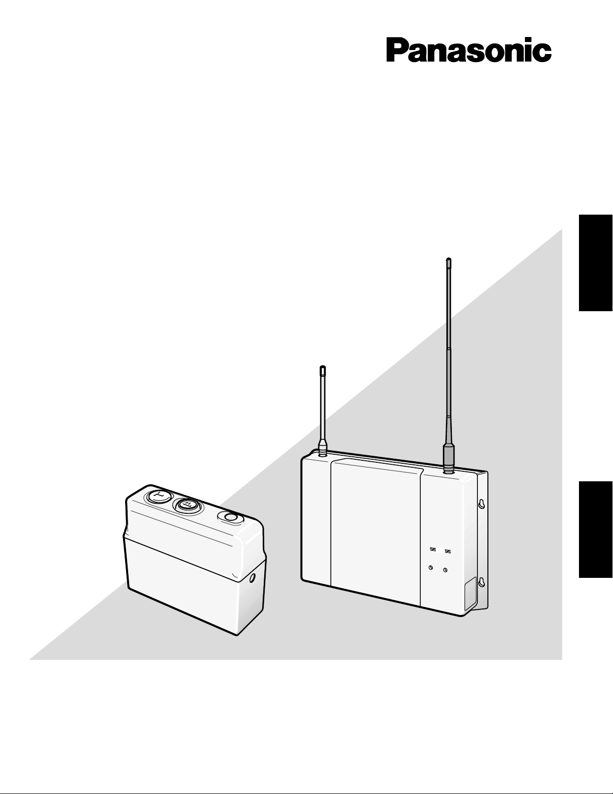
Wireless Communication System
Panasonic
DNR
ULTRAPLEX
POWER
VEHICLE
PRESENT
Operating Instructions
Model No. WX-C1011 Series
Digital Technology
ENGLISHFRANÇAIS
Before attempting to connect or operate this product,
please read these instructions carefully and save this manual for future use.
Page 2
ENGLISH VERSION
CONTENTS
PREFACE ...................................................................................................................................................................................... 3
PRECAUTIONS ............................................................................................................................................................................. 3
PANASONIC WX-C1011 SERIES SYSTEM PARTS AND ACCESSORIES ..................................................................................... 4
MAJOR OPERATING CONTROLS AND THEIR FUNCTIONS ....................................................................................................... 5
SYSTEM CONNECTIONS AND PREPARATIONS........................................................................................................................ 12
OPERATING PROCEDURES ....................................................................................................................................................... 15
TROUBLESHOOTING GUIDE ..................................................................................................................................................... 16
SPECIFICATIONS ........................................................................................................................................................................ 16
CAUTION
RISK OF ELECTRIC SHOCK
DO NOT OPEN
CAUTION: TO REDUCE THE RISK OF ELECTRIC SHOCK,
DO NOT REMOVE COVER (OR BACK).
NO USER-SERVICEABLE PARTS INSIDE.
REFER SERVICING TO QUALIFIED SERVICE PERSONNEL.
The lightning flash with arrowhead symbol, within an equilateral triangle, is
intended to alert the user to the presence of uninsulated "dangerous voltage"
within the product's enclosure that may
SA 1965
SA 1966
be of sufficient magnitude to constitute a
risk of electric shock to persons.
The exclamation point within an equilateral triangle is intended to alert the user
to the presence of important operating
and maintenance (servicing) instructions
in the literature accompanying the appliance.
CAUTION:
It is a violation of Federal Law to begin operating this system prior to obtaining an FCC Radio License.
The FCC ID number for this radio equipment is listed
below.
FCC ID : ACK9TAWX-C1011
The serial number of this product may be found on the rigth
of the unit.
You should note the serial number of this unit in the space
provided and retain this book as a permanent record of your
purchase to aid identification in the event of theft.
Model No. WX-C1011
Serial No.
2
WARNING:
To reduce the risk of fire or electric shock, do not expose this appliance to rain or moisture.
Page 3

PREF ACE
The Panasonic Wireless Communication System operates
on UHF frequencies. It offers multichannel flexibility making
use of state of the art PLL (Phase Locked Loop) technology.
The built-in diversity reception allows the use of two antennas to ensure good performance.
A remote speaker can be added to the system. The Order
Taker transceiver is a one piece, light-weight design with
an easy-to-install battery.
New Functions of the WX-1011
(New Technological Features)
• DNR (Digital Noise Reduction)
The DNR function embodies a new technology exclusive to Panasonic, providing natural sound quality without the disagreeable noise peculiar to digital processing.
• No Talkback Echo
Dijital delay processing eliminates talkback echo from
the order taker.
• TBC (Talkback Automatic Level Control)
Only human voice is identified in a mixed input of customer voice and noise from the menuboard microphone, then its volume is compared with that of the talk
of the order taker to automatically control the talkback
volume level.
ENGLISH
PRECAUTIONS
The UHF wireless communication system is a sensitive,
high quality instrument and should be regarded as such.
Because it is an electrical device, the hazard of electric
shock exists, if it is used carelessly.
In order to utilize the instrument to its fullest potential,
please consider the following precautions;
1. Handle the equipment with care. This equipment contains sensitive components which can be damaged by
improper handling or storage.
2. Refer any servicing to qualified service personnel. Do
not attempt to disassemble the Center Module, Order
Taker or other units. In order to prevent electrical
shock, do not remove screws or covers. There are no
user-serviceable parts inside.
3. Use a dry cloth to clean the Center Module, Order
Taker or other units if soiled or dirty. If necessary, a
mild detergent may be used.
4. Take immediate action if the Center Module or Order
Taker becomes wet. Turn the power off and have the
unit examined by a qualified service personnel. Do not
expose the Center Module or Order Taker to rain or
moisture, or attempt to operate the equipment in wet
areas. Do not operate the equipment if it is wet.
5. Follow normal safety precautions to avoid personal
injury.
6. Properly store beltpack (WITH HEADSET PLUGGED
IN) in storage cabinet to prevent damage to equipment.
7. Replace missing microphone and earpiece covers to
prevent distortion or loss of audio.
8. Repair or replace any defective components.
9. Turn off the Order Taker when not in use, in order to
save the battery life.
10. Charge battery when low battery indicator blinks and a
pulsing high/low beep tone is heard in headset.
11. Clean the Battery Charger in accordance with manufacturer instructions at least once a month.
12. Perform regular preventive maintenance by testing
accessories (headset, batteries etc.)
3
Page 4
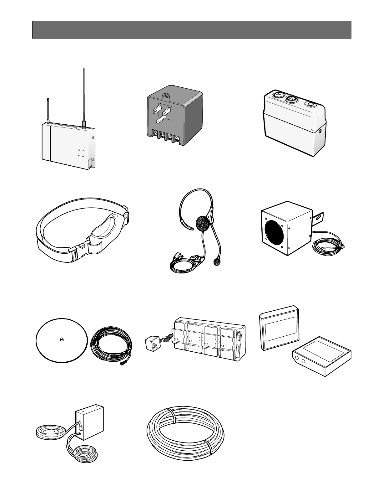
PANASONIC WX-C1011 SERIES SYSTEM P ARTS AND ACCESSORIES
Panasonic
DNR
ULTRA
PLEX
P
O
W
E
R
V
E
H
IC
L
E
PR
E
S
E
N
T
4
PB900
4.8 V 850 nAh
000015
1094
PB900
4.8 V 850 nAh
000021
1094
■ Center Module
WX-C1011
■ Order Taker Case
WX-C1022
■ Power Transformer
WX-C516
■ Headset
WX-C1027A
■ Order Taker
WX-C1020
■ Speaker Microphone
WX-C550
■ External Antenna Kit
WX-C545
■ Vehicle Detector
917-1
4
■ Battery Charger
BC-4
■ Battery
PB-900
■ Speaker/Loop Cable Kit
WX-C687
Page 5
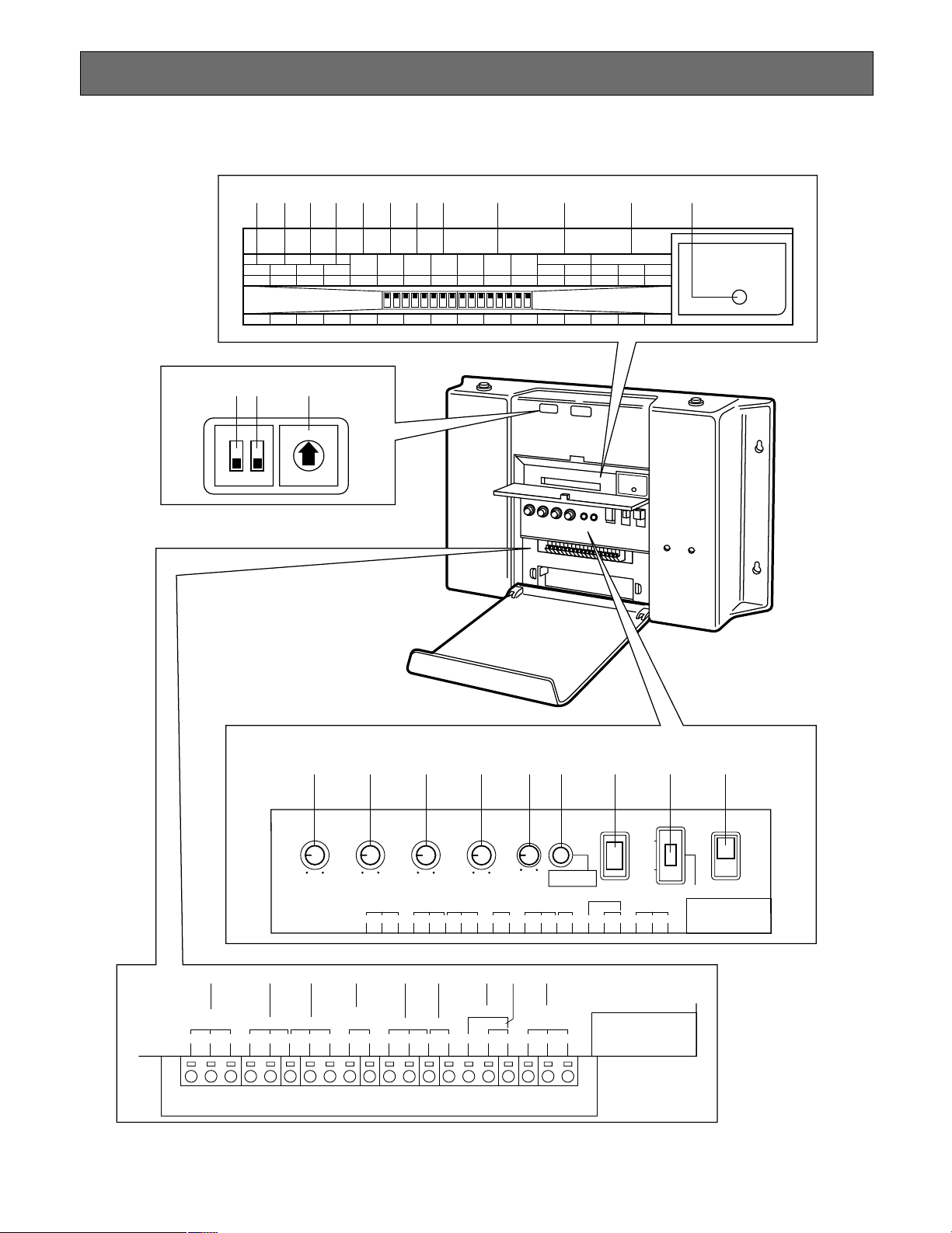
MAJOR OPERATING CONTROLS AND THEIR FUNCTIONS
CIRCUIT
PROTECTOR
OFF
ON
DNR 3
OFF
ON
DNR 2
OFF
ON
DNR 1
OFF
ON
DNR EFFECTT/B LEVEL
TBC 2
OFF
ON
TBC 1
OFF
ON
TALK
MONIT
CHANNEL
SELECT
CHANNEL
MONIT
AUX IN
SELECT
BEEP TIME
SELECT
B
A
OFF
ON
DOT BEEP
G/MIC
CONT IN
0.5S
OFF
ON
PAGE
OFF
ON
TALK
OFF
ON
REMOTE SP
MENU MIC
OFF
ON
AUX IN
ON
12
0
10
OUTBOUND
VOLUME
0 10
INBOUND
VOLUME
0 10
REMOTE SP
VOLUME
0
10
AUX INPUT
VOLUME
0
TALK/PAGE
MONITOR
O/TAKER
TALK LOCK
RELEASE
VEHICLE
DETECTOR
POWER
ON
OFF
OVERRIDE ON
NORMAL
OFF
TALK : RED
PAGE : GREEN
10
BEEP
VOLUME
0
MESSAGE
REPEATER MIC SP 8Ω SP 8Ω
MENU REMOTE
H C CTL H C C CH HGND
INPUT V/DET 12V ACOUTPUT
AUX G/MIC PTT TRANSFORMER
H IN INC HGND GNDCOM LOAD
CAUTION:USE WITH SPECIFED
EQUIPMENT SEE ITS MANUAL
BEFORE CONNECTING
MESSAGE
REPEATER MIC SP 8Ω SP 8Ω
MENU REMOTE
H C CTL H C C CH HGND
INPUT V/DET 12V ACOUTPUT
AUX G/MIC PTT TRANSFORMER
H IN INC HGND GNDCOM LOAD
CAUTION:USE WITH SPECIFED
EQUIPMENT SEE ITS MANUAL
BEFORE CONNECTING
@3@6@2 @1 @0 !9 !8 !7 !6 !5 !4 !3 !2
!1
#5 #2 #1 #0 @9 @7@8#4 #3
!0 o i u y t r e
@5 @4
■ WX-C1011 Center Module
5
Page 6

Setting
Noise
Reduction
Level
DNR1 DNR2 DNR3
DNR1 DNR2 DNR3
DNR1 DNR2 DNR3
DNR1 DNR2 DNR3
No DNR processing
For a relatively quiet
environment
For a general environment.
This balanced setting is
recommended.
Remarks
Sound
Quality
High
Normal
Low
Low
Normal
High
For a very noisy environment. Not so recommended because it seriously
affects sound quality.
6
q Power Indicator (POWER)
This indicates that the center module is fully power-ed.
w Vehicle Detector Indicator LED (VEHICLE
PRESENT) (Amber)
This indicates that a vehicle has been detected.
e Power On/Off Switch (POWER, ON/OFF)
This switch turns the power on and off to the center
module.
r Vehicle Detector On/Over-ride On/Off Switch
(VEHICLE DETECTOR NORMAL, OVERRIDE ON,
OFF)
NORMAL: Set the switch to the NORMAL position
when a vehicle is at the menuboard.
A beep tone is heard on the Order Taker headset.
After the beep tone, the Menuboard Speaker turns
on allowing communication to and from the customer. When the vehicle leaves, the Vehicle
Detector turns off.
OVERRIDE ON: Set the switch to OVERRIDE ON posi-
tion.
The Vehicle Detector is always turned on.
OFF: Set the switch to the OFF position.
A vehicle at the Menuboard is not detected.
No beep tone is heard in Order Taker headset and
the Menuboard Speaker remains off.
t Order Taker Talk Lock Release Switch (O/TAKER
TALK LOCK RELEASE)
This switch is used to release temporarily the Order
Taker Talk Lock mode.
y Talk/Page Indicator (TALK/PAGE MONITOR)
Red: When the Order Taker is in the Talk mode, the
indicator lights red.
Green: When the Order Taker is in the Page mode, the
indicator lights green.
u Auxiliary Input Level Control (AUX INPUT VOLUME)
This controls the input level to the Auxiliary Input
Terminal #1.
i Vehicle Detector Beep Volume Control (BEEP,
VOLUME)
This control sets the vehicle detect alert beep tone for
the Order Taker to the optimum level.
Caution: When the Vehicle Detector On/Override On/
Off Switch r is set to NORMAL position, the beep
tone level of the Remote Speaker is also varied by
turning this control.
o Remote Speaker Control (REMOTE SP VOLUME)
This control sets the output level of the Remote
Speaker to the optimum level.
Note: The line marked on this control is a standard
position for this adjustment.
Adjust this control to the suitable position so that
feedback does not occur.
!0 Inbound Volume Control (INBOUND VOLUME)
This control sets the sound level from the Menuboard
Microphone to the optimum level.
Caution: Adjust this control after setting the Vehicle
Detector On/Override On/Off Switch r to OVERRIDE ON position and the Vehicle Detector
Indicator lights.
Note: The line marked on this control is a standard
position for this adjustment.
Adjust this control to the suitable position so that
feedback does not occur.
!1 Outbound Volume Control (OUTBOUND VOLUME)
This control sets the output level of the Menuboard
Speaker to the optimum level for talking to customer.
Caution: Adjust this control after setting the Vehicle
Detector On/Override On/Off Switch r to OVERRIDE ON position and the Vehicle Detector
Indicator lights.
Note: The line marked on this control is a standard
position for this adjustment.
Adjust this control to the suitable position so that
feedback does not occur.
• The following switches and terminals should be
used by qualified service personnel only.
• To change the setting of the following switches,
turn off the power of the center module, then turn it
back on.
!2 Circuit Protector (CIRCUIT PROTECTOR)
If excessive current flows to the Center Module, the
Circuit Protector is triggered. Turn off the Power
On/Off Switch e first, push in on the red circuit protector and turn on the Power On/Off Switch e again.
If the circuit protector is soon triggered again, consult your dealer or authorized service center for
assistance.
!3 DNR (Digital Noise Reduction) Effect Level
(DNR EFFECT DNR1, DNR2, DNR3, ON/OFF)
These switches are used for noise reduction level
setting.
The more the noise is reduced, the lower will be the
sound quality. The table below shows the
relationship between noise reduction level and
sound quality.
No setting should be done other than shown in the
table.
Page 7

!4 Talkback Level Control (T/B LEVEL TBC1, TBC2,
Setting
Talkback
Level
TBC1 TBC2
TBC1 TBC2
TBC1 TBC2
TBC1 TBC2
Normal set to this position
Talkback level set to 50 %
Talkback level set to 35 %
Talkback level set to 25 %
Remarks
–6 dB
–9 dB
–12 dB
– Talkback off
ON/OFF)
These switches are used for order taker talkback
level setting.
Change the settings if talkback level is too high.
!5 Talk Monitor On/Off Switch (Supplementary Mode
Switch) (TALK MONT OF/OFF)
This DIP switch should be normally be set to the OFF
position.
Consult your servicing dealer before attempting to
change this switch.
!6 Channel Selection Switch (CHANNEL SELECT,
A/B)
This switch selects the frequency between channel
“A” and “B” licensed by the FCC. This switch is normally set to the “A” position. The switch can be set to
“B” position if external interference occurs.
CONTIN: After the vehicle is detected by the vehicle
detector, the beep tone continuously sounds
until the Talk Switch $3 on the Order Taker has
been pressed.
@0 Page On/Off Switch (REMOTE SP PAGE, ON/OFF)
To monitor crew-to-crew Order Taker conversation
with the Remote Speaker, set this switch to the ON
position.
@1 Talk On/Off Switch (REMOTE SP TALK, ON/OFF)
To monitor crew-to-customer Order Taker conversation with the Remote Speaker, set this switch to ON
position.
Note: Do not turn on this switch and Menuboard
Microphone On/Off Switch simultaneously.
@2 Menuboard Microphone On/Off Switch (REMOTE
SP MENU MIC, ON/OFF)
To monitor the voice of a customer by using the
Remote Speaker, set this switch to ON position.
Note: Do not turn on this switch and the Talk On/Off
Switch simultaneously.
@3 Auxiliary Input On/Off Switch (AUX IN, ON/OFF)
Set the switch to the ON position for the Remote
Speaker Output mode.
@4 Frequency Setting Switch
This switch selects the frequency from 8 positions.
Note: The “9” and “0” positions are error mode.
7
!7 Channel Monitor On/Off Switch (CHANNEL
MONIT, ON/OFF)
This switch is used to check if the desired channel is
already used by other systems at the time of installation. This switch is normally set to OFF position.
Note: The Frequency Setting Switch @4 can only be
activated, when the switch is set to the ON position.
!8 Auxiliary Input Selection Switch (AUX IN SELECT,
G/MIC/DDT BEEP)
This switch selects the Auxiliary Input Level.
G/MIC (Gooseneck Microphone):
This can be used as a wired system.
(Input : −62 dBV, balanced)
DDT BEEP (Double Drive Through Beep):
This can be used as a double drive through system.
(Input : −20 dBV, balanced)
!9 Beep Time Selection Switch (BEEP TIME SELECT,
0.5 S/CONTIN)
This switch selects duration of beep tone between
0.5 seconds and continuous modes.
0.5 S: The beep tone sounds for 0.5 seconds after
detecting the vehicle.
@5
Monitor On/Off Switch (ON/2)
This switch should be used as the FCC Channel
Monitor when using the Channel Monitor On/Off
Switch !7.
After setting the Frequency Setting Switch @4 to the
desired position, set this switch.
ON: When the switch is set to the ON position, FM
noise will be output when there is no signal.
2: When the switch is set to the 3 position, the noise
squelch function will be activated.
Monitor On/Off
Channel setting
Monitor position
On/Off Switch
!7 setting position
MONIT OFF
MONIT ON
Switch @6
3
Normal oper-
ation mode
Interference
confirmation
mode
ON
-
FCC channel
Monitor
mode
Page 8

@6 Continuos Transmission On/Off Switch (ON/1)
ON: When the switch is set to the ON position, the
transmission starts by turning on the power of the
Center Module.
1: When the switch is set to the 1 position, the trans-
mission starts with the following conditions.
• The Vehicle Detector On/Override On/Off
Switch r has been set to ON or OVERRIDE
ON position.
• Page or Talk Switch on the Order Taker has
been pressed.
@7 Transformer Terminal (TRANSFORMER 12V AC
GND, LOAD)
Connects with the Power Transformer WX-C516.
@8 Vehicle Detector Terminal (V/DET IN, COM)
Connects with the Vehicle Detector Output Terminal.
@9 Gooseneck Microphone PTT Terminal
(G/MIC PTT IN, COM)
Connects with the PTT cable of the Gooseneck
Microphone.
#0 Auxiliary Output Terminal (AUX OUTPUT GND, H)
Connects with the Auxiliary Input Terminal of the
other Center Module.
The auxiliary output level is –20 dB, unbalanced.
Note: When using the Gooseneck microphone, con-
nect the monitor speaker with amplifier to this terminal.
Note: CTL permits message repeater control by
pressing the TALK switch $3. It is an open collector type and is to be pulled up for use.
#1 Auxiliary Input Terminal (AUX INPUT H, C, GND)
Connects with the Auxiliary Output Terminal of the
other Center Module or with the gooseneck microphone.
When connecting the gooseneck microphone, set
the Auxiliary Input Selection Switch !8 to the G/MIC
position.
#2 Remote Speaker Terminal (REMOTE SP 8 Ω H, C)
Connects with the Remote Speaker.
The audio level is 8 ohms, 2 W, unbalanced.
#3 Menu Speaker Terminal (MENU SP 8 Ω GND, C, H)
Connects with the Menuboard Speaker WX-C550.
The audio level is 8 ohms, 2 W, unbalanced.
#4 Menu Microphone Terminal (MENU MIC H, C,
GND)
Connects with the Menuboard Microphone.
The audio level is –61 dBV, 8 ohms, balanced.
#5 Message Repeater Input
(MESSAGE REPEATER H, C, CTL)
Connect the message repeater here. The signals
from this input are output to the menuboard speaker,
REMOTE speaker and AUX output. The message is
muted when the TALK switch $3 is pressed. The
input level is –24 dBV, unbalanced.
8
Page 9

1234
0
ON
■ WX-C1020 Order Taker
Note: To prevent damage, use a miniature screwdriver to
open this cover.
%0
$6 $7 $8 $9
%2 %3
$1 Volume Control (VOL, OFF/0/10)
This control is used to turn the power on or off and
adjusts the volume of the earphone output on the headset.
Whenever the unit is not in use, turn off the power to
save the battery life.
$2 Battery and Power Indicators (A/B)
These indicate the battery and operating condition as
follows.
A: When the unit is in Channel A mode selected by the
A/B Selection Switch $5 (Normal operating condition), this LED lights.
B: When the unit is in Channel B mode selected by the
A/B Selection Switch $5 (Back-up operating condition), this LED lights
Blink (0.2 sec. On and 4.8 sec. Off) :
Battery Alarm mode
Blink (0.5 sec. On and 0.5 sec. Off) :
This unit is in the Talk-lock mode.
Blink (A and B are turning on alternately) :
This unit is in the error mode.
In this mode, turn off the power of the Order Taker,
then turn it back on.
%1
$5
$4
$3
$1
$2
$3 Talk Switch (T)
Pressing the Talk Switch allows transmission to the
Center Module along with sending the Talk tone.
Talk-Lock On or Off mode can be selected by the TalkLock On/Off Switch $7 on the Order Taker.
To release the Talk-Lock mode immediately, press the
Order Taker Talk Lock Release Switch t on the Center
Module.
Notes:
1. If pressing the Page Switch or A/B Selection Switch
$5 simultaneously with the Talk Switch, the Talk
mode will not work.
2. The transmission to the Center Module is available
with only one Order Taker at a time.
The other Order Takers can not access during the
transmission.
$4 Page Switch (P)
While pressing the Page Switch, you can speak to the
store personnel wearing the Order Taker without being
heard by a customer at the menuboard speaker. After
speaking, release this switch immediately to listen to
the response.
Note: When pressing the Talk Switch or A/B Selection
Switch simultaneously with this switch, the Page
mode can not work.
9
Page 10

$5 A/B Selection Switch (A/B)
This switch selects either Channel A or B on the Order
Taker by using the SDT/DDT Selection Switch %0 on
the Order Taker.
By setting the SDT/DDT Selection Switch %0 to the DDT
position, the A or B channel can be selected by this
switch.
By setting the SDT/DDT Selection Switch %0 to the SDT
position, the A/B Channel Selection is not possible.
Note: When pressing the Page Switch or Talk Switch
simultaneously with this switch, the channel
change is not possible.
%0 Single Drive Through/Double Drive Through
Selection Switch (ON/1)
ON: When this switch is set to the ON position, the
A/B Selection Switch $5 can work. (DDT (Double
Drive Through) mode)
1: When this switch is set to the 1 position, the A/B
Selection Switch does not work. (SDT (Single
Drive Through) mode)
Note: When the setting for the 46 - 50 switches
inside the cover is changed, turn off the power,
then turn it on.
The switches in the dotted line should be used by service personnel or system installers only.
$6 Frequency Setting Switch
This switch selects the frequency from 8 positions .
Note: The “9” and “0” positions are error mode.
The setting position should be matched to the
position of the Frequency Setting switch @4 on
the center module.
$7 Talk-Lock On/Off Switch (ON/4)
This switch selects the Hands-Free On/Off mode.
ON: Electronic Lock Mode for Talk Switch
When this switch is set to the ON position, the
Talk-lock function can be released by Order
Taker Talk Lock Release Switch t on the
Center Module.
4: PTT (Press to Talk) Mode for Talk Switch
$8 Tone Squelch Switch (ON/3)
This switch selects the mode of Tone Squelch
method.
ON: When this switch is set to the ON position, the
audio is output in disregard of the Tone Squelch
signal from the Canter Module.
3: When this switch is set to the 3 position, the audio
is output detecting the Tone Squelch signal from
the Center Module.
Set to the position normally.
%11 Headset Jack
Plug in the headset plug to this jack securely, before
fitting the Order Taker Case.
The jack having a smaller diameter is for the microphone and the larger one is for the earphone.
%2 Battery Lock Lever (EJECT)
Slide this lever to the EJECT position to release the
battery for replacement.
%3 Headset Plug Release Hole
This hole is used to release the Headset plug.
Caution: Be sure to use a miniature screwdriver for
releasing the Headset Jack. To prevent damage of
the equipment, do not pull the Headset Jack Cord.
10
$9 Single Drive Through Lane Selection Switch
(ON/2)
ON: When this switch is set to the ON position,
Channel B can be selected as an initial condition after the power on the Order Taker is turned
on. (The spare channel is used when external
interference occurs)
2: When this switch is set to the 2 position, Channel
A can be selected as an initial condition after
the power on the Order Taker is turned
on.(Usual position)
Note: The switching can be confirmed by using the
Battery and Power Indicators $2 as shown
below.
Red LED lights with the Channel A selection.
Green LED lights with the Channel B selection.
Page 11

■ WX-C550 Speaker Microphone
^1 Input Cord
A pigtail cord is provided for the speaker input. Its
length is approximately 3 meters.
■ WX-C1027A Headset
^2 Mounting Bracket
AU-type mounting bracket with screw holes is provided as a standard accessory with the WX-C550.
■ WX-C516 Power Transformer
&1 Output terminal (SPARE, LOAD, GRD (Ground))
12 V AC, 1600 mA (Listed) is provided at the two terminals indicated as “LOAD” to be used for the Center
Module WX-C1011.
Caution:
Be sure to connect the wire between the GRD
(GROUND) of this terminal and that in the
Transformer Terminal @7 on the Center Module.
To prevent fire or shock hazard, the UL listed
Power Supply Cord, style SVT should be used for
the cable for 12 V AC terminal.
*1 Earphone
*2 Microphone
*3 Cable Clips
Use these clips to attach the cable to your uniform.
*4 Headset Plug
■ WX-C545 External Antenna Kit
(1
(1 Antenna
(222 Antenna Mounting Plate
(2 (3
11
&2 Power Plug
To prevent fire or electrical shock, connect this directly
to a 3-plug grounded receptacle of 120 V AC, 60Hz.
&3 Mounting Hole
A small hole is required to secure the Power Transformer to the wall plates.
(3 Coaxial Cable
Page 12

SYSTEM CONNECTIONS AND PREPARATIONS
Caution: The installation described below should be made by qualified service personnel or system installers.
■ System Connections
Shown below is an example of a basic system connection.
6 - 15m (20 - 50 feet)
External
Antenna (Option)
• The distance between microphone and speaker should be approx. 5cm (2 inches) or more.
Conduit
Center Module
WX-C1011
External
Antenna (Option)
Conduit
Vehicle
Detector
917-1
Microphone
Speaker
Menuboard or
Speaker Post
Loop in Pavement
■ Battery Charge and Replacement
Refer to the Operating Instructions provided with the battery charger. The following procedure is a summary of battery replacement and charging.
12
1. Replace the Battery when the Battery and Power
Indicator on the Order Taker blinks and the pulsing
high/low beep tone is heard in the headset.
2. Slide the Battery Lock Lever on the Order Taker toward
the EJECT position and pull out the discharged
Battery.
EJECT
Caution: Do eject the battery with care.
Otherwise, the battery may be damaged.
3. Insert the discharged Battery into the battery compartment of the Battery Charger and confirm the RED LED
on the front panel of the Battery Charger lights.
4. When the Battery is fully charged, the GREEN LED on
the front panel of the Battery Charger lights. Use only
fully-charged batteries.
5. Insert the fully-charged Battery into the battery compartment of the Order Taker.
Cautions:
1. Do not shortcircuit between ! and @ terminals of
battery.
2. Read the Battery Charger Instruction Manual completely for your personal safety and correct operation.
3. Be sure to charge the battery only after hearing
the high/low beep tone in the headset. Other-wise,
the operating life time may be shortened.
4. Use a fully charged new battery if the battery operating life time has been shortened by incorrect
charging.
Page 13

■ Assembly and Wearing Belt Pack
1. Take a fully charged battery from the Battery Charger.
2. Insert the battery (contact end first) into the battery
compartment of the Order Taker completely.
5. Unsnap the buckle on the belt of Order Taker Case.
6. Put the Order Taker case on the left side of your west.
3. Insert the Headset Plug into the Headset Jack on the
Order Taker and confirm that the plug is completely
inserted into the jack.
4. Insert the Order Taker into the WX-C1022 Order taker
Case.
Note: When putting the Order Taker Case on the right
side of your waist, unsnap the buckle on the belt
and re-attach it in reverse as shown below.
7. Snap the buckle on the belt of Order Taker Case.
13
8. Fasten the belt tightly enough so it will not move
around on your waist.
9. Fasten both uniform clips to your clothing, on the back.
10. Adjust the headset band until it fits comfortably and
securely.
Page 14

11. Position the microphone boom as shown in figure
below.
ATTENTION:
A nickel cadmium battery that is recyclable powers the product you have purchased. At the end
of its useful life, under various state and local
lows, it is illegal to dispose of this battery into
your municipal waste stream. Please call 1-8008-BATTERY for information on how to recycle
this battery.
■ Maintaining the Equipment
(Non-Scheduled Maintenance)
Be sure to use the microphone cover for this headset.
Otherwise, the headset may be damaged by dust or
oil.
Earspeaker Cover Replacement
Replacement of covers and cushion of headset
The earspeaker cover and microphone cover are
washable. After cleaning, be sure they are dry before
returning them to the headset.
Be careful when you slip it on or off the earpiece.
The earspeaker cover, microphone cover and headpad cushion are replaceable for sanitary purposes. To
order the Headset Cover Kit WX-C1025A, call your
dealer.
IMPORTANT
A microphone cover must be used at all times.
Failure to do so CAN cause debris to accumulate
in the microphone port opening and result in an
inoperative headset.
Headpad Cushion Replacement
• Peel off the old cushion
• Clean surface with a warm solution of household
cleaner.
• Remove the protective tape from the new cushion.
• Position the new cushion on the headpad and
press in place.
14
Microphone Cover Replacement
Headpad Cushion Replacement
Page 15

OPERATING PROCEDURES
■ Communication with
Customers
Any store personnel wearing the Order taker with Headset
can have two-way conversations with Drive-thru customers.
All personnel wearing the Order Taker can have two-way
conversations.
1. Turn the Volume Control !4 (VOL, OFF/10) on the
Order Taker to the middle position.
2. When a vehicle arrives at the menuboard speaker, you
will hear a tone in your headset.
Note: The tone duration depends on which switch
position is chosen in the Center Module. The tone
will be either 0.5 seconds or continuous mode.
See detail on major operating controls and their
functions in this instruction on page 5.
■ Communication with Other
Store Personnel
Store personnel wearing the Order Taker can communicate
with each other without being heard by customers.
1. While pressing the Page Switch $4 (PAGE), speak into
the microphone at a normal level. Short beep tone confirms to the users that they are operating in the page
mode.
Note: When pressing Page Switch $4 on two Order
Takers simultaneously, a garbled sound may
occur.
2. Release the Page Switch $4 immediately after speaking. You can hear only when the Page Switch is
released.
3. Talk lock mode and PTT (Press Talk) mode are provided for the Talk function. Consult qualified service personnel for the proper talk mode setting.
4. Listen to the Customer response.
5. Adjust the Volume Control on the Order Taker to the
desirable level for the incoming transmission (customer's response).
Cautions:
1. Only one person can transmit at a time. If another
person tries to use the system while someone else
is talking or paging, they will hear a continuous
beep in the headset.
2. Be sure to make the distance for the communication between/among the Order Takers more than
30 cm (1 foot), and between/among the Center
Module and Order Takers more than 1 meter (3
feet).
3. When the Vehicle Detector is turned on after setting the Beep Time Selection Switch !9 to the 0.5S
position and turning on the Vehicle Detector, the
beep tone can not be heard.
4. When pressing the Talk Switch on the Order
Takers simultaneously, a garbled sound may
occur.
3. Listen to the response from other store personnel.
Caution: Only one person can transmit at a time. If
another person tries to use the system while someone else is talking or paging, they will hear a continuous beep in the headset.
15
Page 16

TROUBLESHOOTING GUIDE
Phenomenon :
Cannot communicate between Order Taker units or to
Menuboard.
Check Points :
1. Is the Power On/Off Switch on the Center Module
turned on.
2. Check A.C. power at outlet.
3. Push red circuit Breaker Button.
4. Consult your dealer or authorized service center.
Phenomenon :
Cannot talk to or hear customer at Menuboard.
Communication between store personnel in store is
O.K.
Check Point :
Check to see if the Vehicle Detector Indicator q
(VEHICLE PRESENT) located in the lower right corner
of Center Module, lights when a vehicle drives up the
Speaker post/Menuboard, if not check the following.
1. Is the Vehicle Detector plugged in ?
2. Does the VEHICLE PRESENT Indicator light in the
lower right corner of the Center Module?
If not check the A.C. outlet and fuse of the Vehicle
Detector.
If the power and fuse are operational, consult the
authorized service center.
Phenomenon :
Speaker is always live from customer.
Check Points :
1. Reset the Vehicle Detector. With no car at the Speaker
post/Menuboard, remove and reinstall the fuse on the
side of the Detector.
2. If the same phenomenon remains after performing step
#1, consult your dealer or authorized service center.
Phenomenon :
Constant beep when a car comes to the Speaker post/
Menuboard. (Stops when the Talk button is pressed)
Check Points :
Incorrect switch setting of the Beep Time Selection
Switch !9 on the Center Module. Set this switch to 0.5 S
position.
Phenomenon :
Cannot page or talk in certain areas.
Check Points :
1. Make sure there is no metal obstruction blocking the
Center Module.
2. It may be necessary to extended one or both antennas
to areas where the reception is poor.
Consult your dealer or authorized service center.
SPECIFICATIONS
WX-C1011 Center Module
Operating Frequency: Transmit; 469.0125 MHz - 469.4125 MHz
Receive; 464.0125 MHz - 464.4125 MHz
Type of Emission: F3
Type of Antenna: 1/4 wavelength whip antenna (short white antenna)
1/2 wavelength whip antenna (long black antenna)
Power Supply: 12 V AC, 60 Hz (Use WX-C516 Power Transformer)
Power Consumption: 13 W
Menuboard Speaker Output: 2 W, 8 Ω
Remote Speaker Output: 2 W, 8 Ω
Vehicle Detector Input: Normally Open (close contact requires vehicle presence)
Dimensions: 330 mm (W) X 210 mm (H) X 62 mm (D)
13” (W) X 8-1/4” (H) X 2-7/16” (D)
Weight (Including Antenna) : 1.44 kg (3.17 lbs.)
Dimensions and weights indicated are approximate.
Specifications are subject to change without notice.
16
Page 17

Panasonic Information Systems Company
A Unit of Matsushita Electric Corporation of America
1707 North Randall Road, Elgin, IL 60123-7847 (847) 468-4600
Panasonic Canada Inc.
5770 Ambler Drive, Mississauga,
Ontario, L4W 2T3 Canada (905)624-5010
2001 © Matsushita Communication Industrial Co., Ltd. All rights reserved. N0900-1031 A8QA5609BN Printed in Japan
N 19 Imprimé au Japon
 Loading...