

Page 1

Operating Instructions
WV-X6533LN
Network Camera
Model No. WV-X6533LN
WV-S6532LN
WV-X6533LNS
WV-S6532LNS
The model number is abbreviated in some descriptions in this manual.
Page 2

X6533
S6532
Preface
Preface
About the user manuals
There are 3 sets of operating instructions as follows.
• Operating Instructions (this document): Explains how to perform the settings and how to operate this
camera.
• Important Information: Provides information about the cautions required for safely using and installing this
camera.
• Installation Guide: Explains how to install and connect devices.
The screens used in these operating instructions show the case of WV-X6533LN. Depending on the model
used, the screens shown in the explanations may differ to the actual camera screens.
Note
• “Control No.: C****” used in this document should be used to search for information on the Panasonic
support website and will guide you to the right information.
About notations
The following notations are used when describing the functions limited for specified models.
The functions without the notations are supported by all models.
: The functions with this notation are available when using the model WV-X6533LN,
WV-X6533LNS.
: The functions with this notation are available when using the model WV-S6532LN,
WV-S6532LNS.
Abbreviations
The following abbreviations are used in these operating instructions.
Microsoft Windows 10 is described as Windows 10.
Microsoft Windows 8.1 is described as Windows 8.1.
Microsoft Windows 7 is described as Windows 7.
Internet Explorer 11 is described as Internet Explorer.
SDXC/SDHC/SD memory card is described as SD card or SD memory card.
Universal Plug and Play is described as UPnP™ or UPnP.
For administrator registration
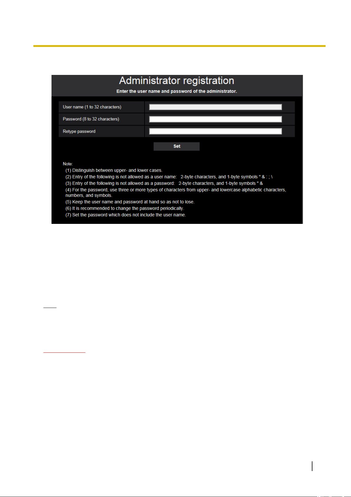
At the time of first access to the camera (or at the time of initialization), the registration screen will be displayed.
2 Operating Instructions
Page 3
Preface
Define the user name and the password for the administrator, and enter them correctly. Hereafter, they can
be used for login.
[User name (1 to 32 characters)]
Enter the user name of the administrator.
Available number of characters: 1 - 32 characters
Unavailable characters: 2-byte characters, and 1-byte symbols " & : ; \
[Password (8 to 32 characters)]/[Retype password]
Enter the administrator password.
Available number of characters: 8 - 32 characters
Unavailable characters: 2-byte characters, and 1-byte symbols " &
Note
• Distinguish between upper- and lower cases.
• For the password, use three or more types of characters from upper- and lowercase alphabetic
characters, numeric characters, and symbols.
• Set the password which does not include the user name.
IMPORTANT
• If you forgot or do not know the password or user name, the camera must be initialized. Because all
settings other than preset position settings are deleted when the camera is initialized, make sure to
keep the information secure from third parties. Refer to “Parts and functions” section in the Important
Information in the supplied CD-ROM for more information about initializing the camera.
• It is recommended to change the password periodically.
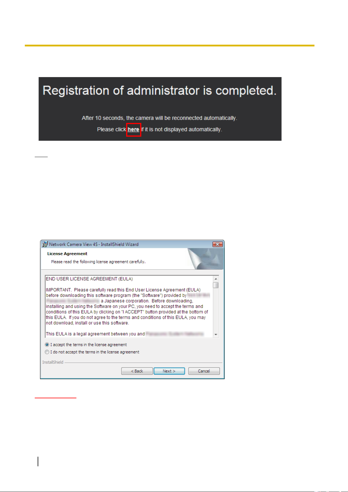
The registration completion screen will be displayed after registering a user name and password of the
administrator. After 10 seconds, the camera will be reconnected automatically. Please click “here” if it is not
displayed automatically.
Operating Instructions 3
Page 4
Preface
When the camera is reconnected to, an authentication window is displayed. Enter the registered user name
and password to start operation.
Note
• When the administrator’s user name and password are registered, pan, tilt, zoom function will start
automatically.
Viewer software
In order to display H.265 (or H.264) images, send/receive audio to/from the camera, and play images saved
on the SD memory card, the “Network Camera View 4S” (ActiveX) viewer software must be installed. This
software can be installed directly from the camera or by selecting the [Install] button next to [Viewer
Software] on the menu of the CD-ROM provided, and then following the on-screen instructions.
IMPORTANT
• The default setting of “Automatic installation” is “On”. Follow the instructions on page 276 when the
message is displayed on the information bar of the browser.
• Depending on the software environment of your PC, it may take time for the message to be displayed
on the information bar of the browser.
4 Operating Instructions
Page 5

Preface
• If you display the “Live” page on a PC and click the [Viewer software] button, the installation screen for
ActiveX, which is required for viewing camera images, is displayed. Follow the on-screen instructions
and install the software. When displayed JPEG images (still images), there is no need to install ActiveX.
• When the install wizard is displayed again even after completing the installation of the ActiveX, restart
the PC.
• The viewer software used on each PC should be licensed individually. The number of installations of
the viewer software from the camera can be checked on the [Upgrade] tab of the “Maintenance” page
(®page 247). Refer to your dealer for the software licensing.
Operating Instructions 5
Page 6

Table of Contents
Table of Contents
1 Operations ................................................................................................9
1.1 Monitor images on a PC ...................................................................................................9
1.1.1 Monitor images from a single camera ..............................................................................9
1.1.2 About the “Live” page .....................................................................................................12
1.1.3 Monitor images from multiple cameras ..........................................................................18
1.2 Monitor images on a cellular phone/mobile terminal ..................................................21
1.2.1 Monitor images on a cellular phone ...............................................................................21
1.2.2 Monitor images on a mobile terminal (including smartphones) ......................................23
1.3 Record images on the SD memory card manually ......................................................30
1.4 Action at an alarm occurrence .......................................................................................32
1.4.1 Alarm type ......................................................................................................................32
1.4.2 Action at an alarm occurrence ........................................................................................32
1.5 Transmit images onto an FTP server ............................................................................34
1.5.1 Transmit an alarm image at an alarm occurrence (Alarm image transmission) .............34
1.5.2 Transmit images at a designated interval or period (FTP periodic image
transmission) ..................................................................................................................34
1.5.3 Save images on the SD memory card when images fail to transmit using the FTP periodic
image transmission function ...........................................................................................35
1.6 Display the log list ..........................................................................................................36
1.7 Playback of images on the SD memory card ...............................................................40
1.7.1 Playback “JPEG(1)”/“JPEG(2)”/“JPEG(3)” images saved to the SD memory
card ................................................................................................................................40
1.7.2 Playback “Stream(1)”/“Stream(2)”/“Stream(3)”/“Stream(4)” images saved to the SD
memory card ..................................................................................................................43
2 Settings ...................................................................................................46
2.1 About the network security ............................................................................................46
2.1.1 Equipped security functions ...........................................................................................46
2.2 Display the setup menu from a PC ................................................................................47
2.2.1 How to display the setup menu ......................................................................................47
2.2.2 How to operate the setup menu .....................................................................................48
2.2.3 About the setup menu window .......................................................................................49
2.3 Use Easy Setup [Easy Setup] ........................................................................................51
2.3.1 Configure the Internet settings [Internet] ........................................................................51
2.3.2 Configure an event action [Event action] ........................................................................52
2.3.2.1 Configure the schedule/alarm (event function type setup menu) ................................55
2.3.2.2 Alarm: Configure the terminal and VMD (alarm setup menu) ......................................56
2.3.2.3 Alarm: Configure the alarm function type (Alarm function type setup menu) ..............59
2.3.2.4 Alarm: Configure the details for image transfer or recording conditions ......................60
2.3.2.5 Alarm: Configure the output terminal ...........................................................................62
2.3.2.6 Alarm: configure the mail notifications and mail server ...............................................63
2.3.2.7 Schedule: Configure SD recording or FTP periodic image transmission (schedule
function type setup menu) ...........................................................................................65
2.3.2.8 Schedule: Set SD memory recording (video recording setup menu) ..........................65
2.3.2.9 Schedule: Configure FTP periodic image transmission (FTP periodic image transmission
setup menu) .................................................................................................................67
2.4 Configure the basic settings of the camera [Basic] ....................................................71
2.4.1 Configure the basic settings [Basic] ...............................................................................71
2.4.2 Configure the settings relating to the SD memory card [SD memory card] ....................79
2.4.3 Configure the settings relating to alteration detection [Alteration detection] ..................88
2.4.4 How to configure alteration detection settings ................................................................90
2.4.4.1 Generation of the CRT key (encryption key) ...............................................................90
6 Operating Instructions
Page 7

Table of Contents
2.4.4.2 Generation of CSR (Certificate Signing Request) .......................................................91
2.4.4.3 Installation of the certificate issued by CA ...................................................................93
2.4.4.4 Configuration of alteration detection ............................................................................94
2.4.5 Access copy images saved on the SD memory card onto the PC [SD memory card
images] ...........................................................................................................................95
2.4.6 Configure the directory of the PC that images will be downloaded to [Log] ...................97
2.4.7 Configure the overlay image function [Overlay image] ...................................................99
2.5 Configure the settings relating to images and audio [Image/Audio] .......................102
2.5.1 Configure the settings relating to the image capture mode [Image] .............................102
2.5.2 Configure the settings relating to JPEG images [Image] ..............................................103
2.5.3 Configure the settings relating to Stream [Image] ........................................................105
2.5.4 Configure the settings relating to the camera operations [Cam. Function] ..................111
2.5.5 Configure the settings relating to images and the preset positions [Image/
Position] ........................................................................................................................115
2.5.5.1 Configure the settings relating to image quality (“Image adjust” setup menu) ..........116
2.5.5.2 Set mask areas ..........................................................................................................126
2.5.5.3 Configure the settings relating to the preset positions (“Preset position” setup
menu) ........................................................................................................................128
2.5.5.4 Configure the settings relating to the auto pan function (“Auto pan” setup
menu) ........................................................................................................................132
2.5.5.5 Configure the settings relating to patrol (“Patrol” setup menu) ..................................134
2.5.5.6 Configure the settings relating to auto track (“Auto track” setup menu) ....................136
2.5.5.7 Configure the settings relating to direction/angle setting (“Direction/Angle” setup
menu) ........................................................................................................................142
2.5.5.8 Configure the settings relating to the privacy zone (“Privacy zone” setup
menu) ........................................................................................................................143
2.5.5.9 Configure the VIQS setting ........................................................................................146
2.5.5.10 Configure the VIQS area ...........................................................................................149
2.5.6 Configure the settings relating to audio [Audio] ............................................................151
2.6 Configure the multi-screen settings [Multi-screen] ...................................................155
2.7 Configure the alarm settings [Alarm] ..........................................................................157
2.7.1 Configure the settings relating to the alarm action [Alarm] ...........................................157
2.7.2 Configure the settings relating to the output terminal [Alarm] ......................................159
2.7.3 Change the AUX name [Alarm] ....................................................................................160
2.7.4 Configure the settings relating to the camera action on alarm occurrence
[Alarm] ..........................................................................................................................161
2.7.4.1 Configure the settings relating to Preset per sender (“Preset per sender” setup
menu) ........................................................................................................................164
2.7.4.2 Configure settings relating to image quality on alarm action .....................................165
2.7.4.3 Configure settings relating to alarm E-mail notifications ............................................166
2.7.4.4 Configure settings relating to FTP transmissions of alarm images ...........................167
2.7.4.5 Configure settings relating to recording to an SD memory card when an alarm
occurs ........................................................................................................................168
2.7.4.6 Configure settings relating to Panasonic alarm protocol notification when an alarm
occurs ........................................................................................................................169
2.7.4.7 Configure settings relating to HTTP alarm notification when an alarm occurs ..........170
2.7.5 Configure the VMD settings [VMD area] ......................................................................170
2.7.6 Set the VMD areas [VMD area] ....................................................................................173
2.7.7 Configure the settings relating to the audio detection [Audio detection] ......................175
2.7.8 Configuration of the settings relating to alarm notification [Notification] .......................177
2.7.8.1 Configure the settings relating to Panasonic alarm protocol .....................................178
2.7.8.2 Configure the settings relating to HTTP alarm notification ........................................180
2.8 Configure the settings relating to the authentication [User mng.] ...........................182
2.8.1 Configure the settings relating to the user authentication [User auth.] .........................182
2.8.2 Configure the settings relating to the host authentication [Host auth.] .........................185
Operating Instructions 7
Page 8

Table of Contents
2.8.3 Configure IEEE 802.1X [IEEE 802.1X] .........................................................................187
2.8.4 Configure the data encryption settings [Data encryption] .............................................190
2.9 Configuring the network settings [Network] ..............................................................193
2.9.1 Configure the network settings [Network] .....................................................................193
2.9.2 Configure advanced network settings [Advanced] .......................................................197
2.9.2.1 Configure the settings related to sending E-mails .....................................................198
2.9.2.2 Configure the settings related to FTP transmission ...................................................203
2.9.2.3 Configure the settings relating to the NTP server ......................................................207
2.9.2.4 Configure the UPnP settings .....................................................................................208
2.9.2.5 Configure the HTTPS settings ...................................................................................210
2.9.2.6 Configure the settings relating to DDNS ....................................................................211
2.9.2.7 Configure the settings relating to SNMP ...................................................................213
2.9.2.8 Configure the QoS settings .......................................................................................214
2.9.3 How to configure HTTPS settings ................................................................................216
2.9.3.1 Select the certificate to use when accessing with HTTPS .........................................217
2.9.3.2 Obtaining the root certificate ......................................................................................217
2.9.3.3 Configuration of HTTPS connections ........................................................................223
2.9.3.4 Generation of the CRT key (SSL encryption key) .....................................................224
2.9.3.5 Generation of CSR (Certificate Signing Request) .....................................................225
2.9.3.6 Installation of the CA certificate .................................................................................226
2.9.4 Access the camera using the HTTPS protocol (for pre-installed certificate) ................227
2.9.4.1 Configuration of the host file ......................................................................................227
2.9.5 Access the camera using the HTTPS protocol (for CA Certification) ...........................232
2.9.6 How to configure the settings relating to DDNS ...........................................................233
2.9.6.1 Configuration of the DDNS service (Example of the “Viewnetcam.com”
service) ......................................................................................................................234
2.9.6.2 When using “Dynamic DNS Update” .........................................................................237
2.9.6.3 When using “Dynamic DNS Update(DHCP)” ............................................................238
2.10 Configure the settings relating to the schedules [Schedule] ...................................239
2.10.1 How to set the schedules .............................................................................................242
2.10.2 How to delete the set schedule ....................................................................................244
2.11 Maintenance of the camera [Maintenance] .................................................................246
2.11.1 Check the system log [System log] ..............................................................................246
2.11.2 Upgrade the firmware [Upgrade] ..................................................................................247
2.11.3 Check the status [Status] .............................................................................................248
2.11.4 Reset the settings/Reboot the camera [Default reset] ..................................................251
2.11.5 Settings data/backing up or restoring logs [Data] .........................................................252
2.12 Display the Panasonic support website [Support] ....................................................254
3 Others ....................................................................................................255
3.1 Using the CD-ROM ........................................................................................................255
3.1.1 About the CD launcher .................................................................................................255
3.1.2 Installing Panasonic “IP Setting Software” ...................................................................256
3.1.3 Installing the manuals ...................................................................................................257
3.1.4 Installing the Viewer software .......................................................................................257
3.1.5 Configure the network settings of the camera using the Panasonic “IP Setting
Software” ......................................................................................................................258
3.2 About the displayed system log ..................................................................................261
3.3 Troubleshooting ............................................................................................................266
3.4 Directory structure of drive B ......................................................................................278
8 Operating Instructions
Page 9
1 Operations
1.1 Monitor images on a PC
The following are descriptions of how to monitor images from the camera on a PC.
1.1.1 Monitor images from a single camera
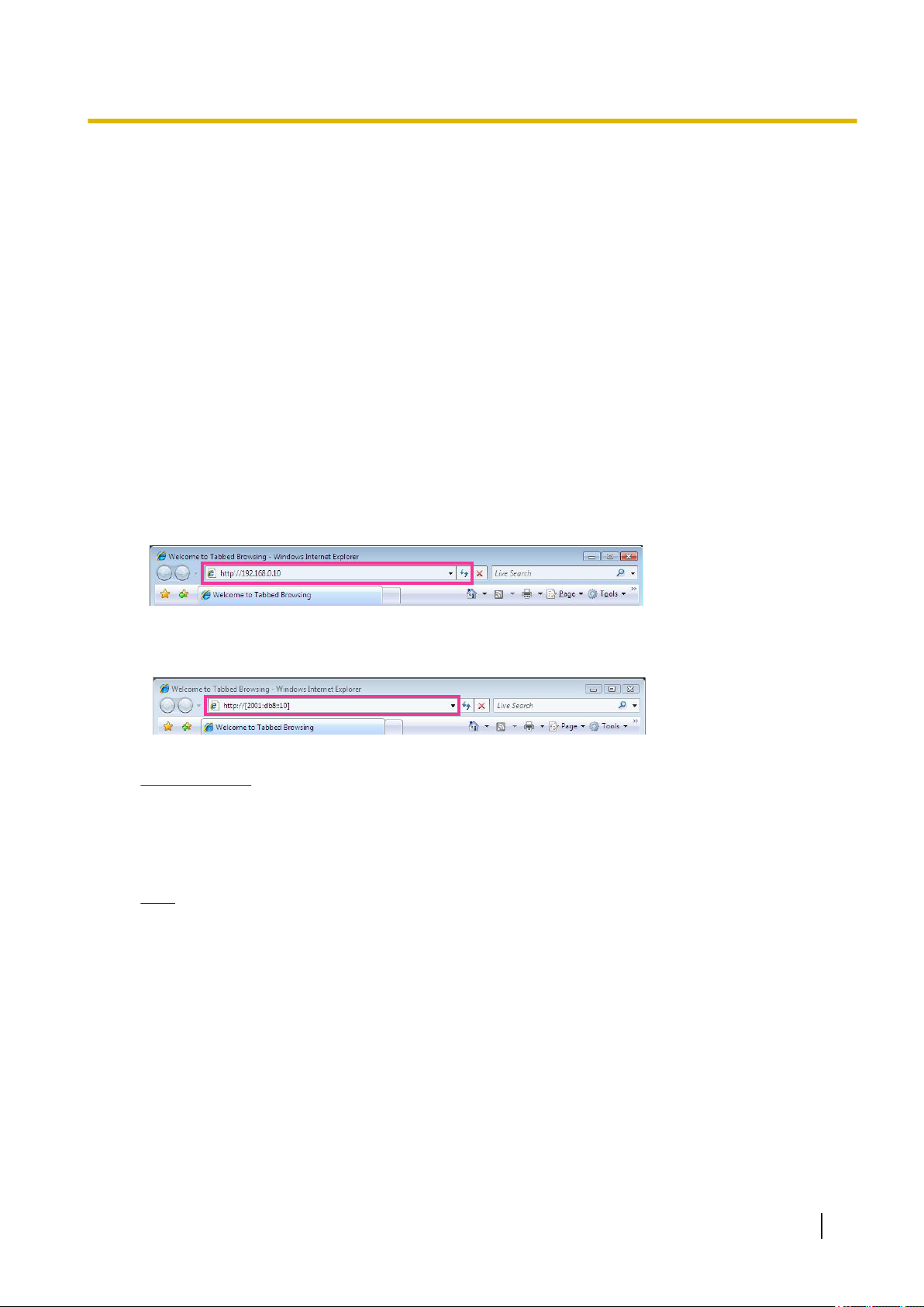
1. Start up the web browser.
2. Enter the IP address designated using the Panasonic “IP Setting Software” in the address box of the
browser.
• Example when entering an IPv4 address: http://URL registered using IPv4 address
http://192.168.0.10/
• Example when entering an IPv6 address: http://[URL registered using IPv6 address]
http://[2001:db8::10]/
<Example of IPv4 access>
1 Operations
<Example of IPv6 access>
IMPORTANT
• When the HTTP port number is changed from “80”, enter “http://IP address of the camera + : (colon)
+ port number” in the address box of the browser. (Example: http://192.168.0.11:8080)
• When the PC is in a local network, configure the proxy server setting of the web browser (under
[Internet Options...] under [Tools] of the menu bar) to bypass the proxy server for the local address.
Note
• Refer to page 227 and page 232 for further information about the case in which “HTTPS” is
selected for “HTTPS” - “Connection” on the [Advanced] tab of the “Network” page (®page 193).
Operating Instructions 9
Page 10
1 Operations
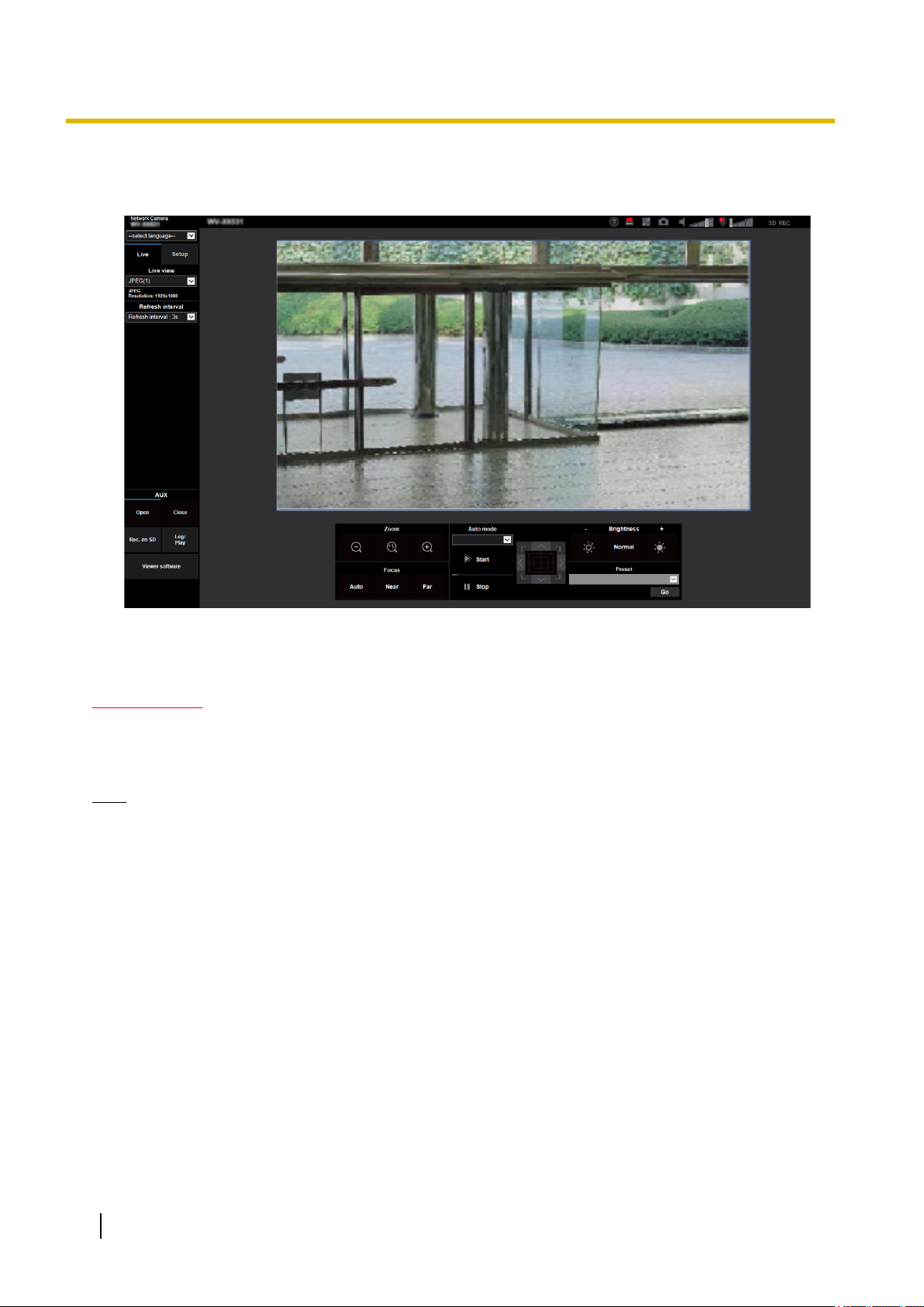
3. Press the [Enter] key on the keyboard.
→ The “Live” page will be displayed. Refer to page 12 for further information about the “Live” page.
When “On” is selected for “User auth.”, the authentication window will be displayed before displaying live
images for the user name and password entries.
IMPORTANT
• It is recommended to change the password periodically.
• When displaying multiple H.265 (or H.264) images on a PC, images may not be displayed depending
on the performance of the PC.
Note
• The maximum number of concurrent access user is 14 including users who is receiving H.265 (or H.
264) images and users who are receiving JPEG images. Depending on the set values for “Bandwidth
control(bit rate)” and “Max bit rate (per client)*”, the maximum concurrent access number may be 14
or less users. When 14 users are concurrently accessing, the access limit message will be displayed
for users who subsequently attempt to access. When “Multicast” is selected for “Transmission type” of
“Stream”, only the first user who accessed to monitor H.265 (or H.264) images will be included in the
maximum number. The second and subsequent users who are monitoring H.265 (or H.264) images
will not be included in the maximum number.
• If you set the “Stream transmission” (®page 105) to “On”, an H.265 (or H.264) image will be displayed
based on the settings of the “Stream encoding format”. If you set the “Stream transmission” (®page
105) to “Off”, a JPEG image will be displayed. A JPEG image can be displayed even if the “Stream
transmission” is set to “On”, but in that case, the transmission interval of the JPEG image will be limited
to maximum 5 fps.
• The refresh interval may become longer depending on a network environment, PC performance,
photographic subject, access traffic, etc.
<Refresh interval of JPEG images>
When “On” is selected for “Stream transmission”
max. 5fps
When “Off” is selected for “Stream transmission”
10 Operating Instructions
Page 11

max. 30fps
1 Operations
Operating Instructions 11
Page 12
Q
G
H
I
J
K L M N
TR U
V W XS
Y
O
P
A
C
E
D
F
B
1 Operations
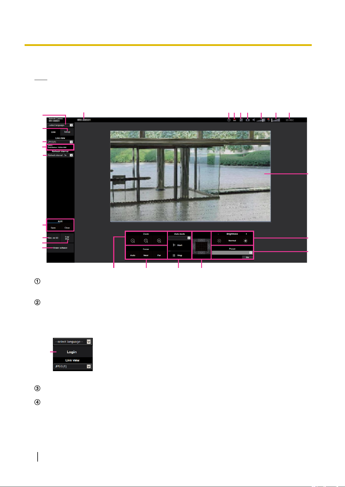
1.1.2 About the “Live” page
Note
• The buttons and setting items displayed on the “Live” page can be changed depending on the user
rights of the accessing user. You can set the user right settings from “User auth.” under “User mng.”.
(®page 182)
[select language] pull-down-menu
The camera’s display language can be selected. The default language can be set in the [Menu language]
in the [Basic] settings. (®page 71)
[Login] button
This button is displayed when “User auth.” is “On” and a person other than the administrator logs in, or
when “User auth.” is “Off” and “Guest User” is set to “Use”. (®page 182)
Even in the above case, the [Login] button will not be displayed if “Host auth.” is set to “On”, and the camera
browser is opened from a host with administrator rights.
If login fails, close all the browsers, open the “Live” page and login once again.
[Setup] button
*1
Displays the setup menu.
[Live view] pull-down menu
You can select and switch to the image to be displayed in the main area from the following:
Stream(1)/Stream(2)/Stream(3)/Stream(4)/JPEG(1)/JPEG(2)/JPEG(3)/Multi-screen
The image in the main area is displayed based on the contents set in Stream(1) – (4) (®page 105),
JPEG(1) – (3) (®page 103), or Multi-screen (®page 155).
12 Operating Instructions
Page 13

1 Operations
Also the first stream displayed when you accessed the camera can be set from “Initial display stream” of
the [Image] tab. For “Multi-screen”, you can set the “Initial display” in the [Multi-screen] tab.
Note
• When “2048´1536”, “1920´1080”, “1280´960” or “1280´720” is selected for the image capture
size, it may become smaller than the actual size depending on the window size of the web browser.
Stream information display
Displays the setup for stream encoding format, image capture size, bit rate, and frame rate for the live view
of a stream.
Note
• Displays the values set in the stream. The actual bit rate and frame rate vary depending on the
network environment and the used PC.
[Refresh interval] pull-down menu
This pull-down menu will be displayed only when a JPEG image is displayed. Use it to select the display
method of the JPEG image.
• MJPEG: Uses viewer software to display JPEG images successively as MJPEG (Motion JPEG). Not
available if the viewer software is not installed.
• Refresh interval : 1s/Refresh interval : 3s/Refresh interval : 5s/Refresh interval : 10s/Refresh
interval : 30s/Refresh interval : 60s: Refreshes JPEG format (still images) images at the specified
interval.
Note
• Depending on the network environment or the PC used, JPEG format (still images) images may
not be refreshed at the specified interval.
• For the JPEG image with the data encryption set to “On”, the [Refresh interval] pull-down menu
will not be displayed.
[AUX] button
*2
These buttons will be displayed only when “Terminal 3” of “Alarm” is set to “AUX output” on the setup menu.
(®page 56)
• [Open] button: The status of the AUX connector will be open.
• [Close] button: The status of the AUX connector will be closed.
Note
• The names of “AUX”, “Open” and “Close” can be changed. (®page 160)
[Rec. on SD] button
The [Rec. on SD] button will be displayed only when “Manual” is selected for “Save trigger” on the [SD
memory card] tab. (®page 84)
Click this button to manually record images on the SD memory card. Refer to page 30 for descriptions
of how to manually record images on the SD memory card.
[Log] button
*2
When the [Log] button is clicked, the log list will be displayed and images saved on the SD memory card
can be played.
Refer to page 36 for further information about the log list and for how to play images on the SD memory
card.
[Viewer software] button
Starts installation of the viewer software for display. This button will not be available if the viewer software
is already installed on the PC, or if the “Automatic installation” of the [Viewer software
(nwcv4Ssetup.exe)] in the [Basic] tab is set to “Off”. (®page 76)
[Zoom] button
•
: Click this button to adjust the zoom ratio to the “Wide” side.
*2
*2
• : Click this button to set the zoom ratio to x1.0.
Operating Instructions 13
Page 14

1 Operations
• : Click this button to adjust the zoom ratio to the “Tele” side.
[Focus] button
•
• : Click this button to adjust the focus to the “Near” side.
• : Click this button to adjust the focus to the “Far” side.
Note
Auto mode
Select an operation from the pull-down menu and click the [Start] button. The selected operation will start.
Click the [Stop] button to stop the operation. The selected operation will stop when the camera (panning/
tilting/ zooming/ focusing) is operated or when an action to be taken according to the settings for “Self
return” (®Page 111) or for “Camera action on alarm” (®Page 161) starts.
*2
: Click this button to adjust the focus automatically.
• When shooting the following place or the following subjects, focus may not be
adjustedautomatically. Adjust the focus manually.
– Shiny or strongly reflective subject
– Subject through the glass with dew or smudge
– Two subjects whose distances from the camera are different
– Less contrast subject (e.g. white wall)
– Horizontal-striped subject such as a window blind
– Inclined subject
– Dark subjects
*2
Note
• Operating in the auto mode for a long period of time wears the driving parts, and the replacement
interval of those parts may be shortened. Refer to the Important Information in the supplied
CD-ROM for the consumable parts.
• Auto track: Automatically tracks objects in the shooting area.
Note
• The auto-track function is not available under the following conditions:
– When “Image capture mode” is set to “2 mega pixel [16:9](60fps mode)”
– When “On” is selected for “Stabilizer”
– When other than “Off” is selected for “Smart Facial Coding” of “Smart Coding” for “Stream(1)”
– When “Maximum shutter” of “Image adjust” - “Light control mode” is the following:
Max.2/30s/ Max.4/30s/ Max.6/30s/ Max.10/30s/ Max.16/30s
• With the Auto track feature, objects moving in the screen are picked out and automatically tracked.
• In the following situations, targets may not be able to be tracked, or false detections may occur.
– when there is little contrast between the subject and the background
– when dirt, drip, or splash is on the front panel
– when there are large changes to the lighting intensity
– when there are many moving objects other than the subject
– when there is a change on the optical axis (in a vertical direction) of the camera
– when the subject moves directly underneath the camera
– when there is harsh flickering
– when there are reflections from light entering the front panel due to reflections from a window
or road, or from a backlight
– when the target is hidden behind a utility pole or other objects
– when the subject passes by other moving objects
– when the target moves too fast or too slow
– when the camera is shaking
14 Operating Instructions
Page 15

1 Operations
• When the zoom ratio is set to the “Tele” side, it may be difficult to obtain accuracy with the auto
tracking function. It is recommended to use the auto tracking function with setting the zoom ratio
to the “Wide” side.
• During auto tracking, if the camera is operated using the control pad or by other methods, or if an
alarm occurs, auto tracking is stopped.
• Auto pan: Automatically pans between the start position and the end position set in advance
(®Page 132).
Even when the camera is operated for zooming or focusing, the camera continues panning. (However,
panning will stop when the zoom button (x1) is clicked.)
• Preset sequence: Automatically moves to the preset positions (®Page 128) orderly (start from the
lowest preset position number).
• Patrol 1-4: Performs patrols 1-4 that were set in advance. (®Page 134)
Control pad/buttons
Left-click on the control pad or buttons to adjust the horizontal/vertical position of the camera (panning/
tilting). Panning/tilting speed will be faster if a clicked point gets farther from the center point of the control
pad.
It is also possible to pan/tilt the camera by dragging the mouse.
Zoom and focus can be adjusted by right-clicking. When an upper/lower area of the control pad is
right-clicked, the displayed image will be zoomed in/out on. When a left/right area is right-clicked, the focus
will be adjusted to the Near/Far side.
Zoom can also be adjusted using the mouse wheel.
[Brightness] buttons
The brightness is adjustable from 0 to 255. Click the
button to make the image darker. If you click the [Normal] button, the display will be reset to default.
[Preset]
*2
Select a preset position from the pull-down menu and click the [Go] button. The camera will move to the
selected preset position (®Page 128). “H” next to the preset position number indicates the home position.
When “Home position” is selected, the camera will move to the home position. (®Page 111)
When “Preset ID” is registered for a preset position, the registered preset ID will be displayed next to the
preset position number.
Camera title
The camera title entered for “Camera title” on the [Basic] tab will be displayed. (®page 72)
Support button
When this button is clicked, the support site below will be displayed in a newly opened window. This website
contains technical information, FAQ, and other information.
https://security.panasonic.com/support/
Alarm occurrence indication button
When an alarm occurs, the display flashes. When this button is clicked, the output terminal will be reset
and this button will disappear. (®page 32)
*2
*2
button to make the image brighter, or click the
*2
Note
• Since the blinking of the alarm occurrence indication button is not coupled to recording images to
the SD memory card, forwarding E-mails, or other operations, check the settings of each operation
separately.
Full screen button
Images will be displayed on a full screen. If the full screen button is clicked once when the image displayed
in the main area is smaller than the main area, the image is displayed corresponding to its image capture
size. If the full screen button is clicked once when images are displayed corresponding to their image
capture sizes, images are displayed in full screen. To return to the “Live” page when displaying an image
in full screen, press the [Esc] key.
Operating Instructions 15
Page 16

1 Operations
Snap shot button
Click this button to take a picture (a still picture). The picture will be displayed on a newly opened window.
When right-clicking on the displayed image, the pop-up menu will be displayed. It is possible to save the
image on the PC by selecting “Save” from the displayed pop-up menu.
When “Print” is selected, printer output is enabled.
Note
Mic input button
Turns on/off the audio reception (hear audio from the camera on a PC). This button will be displayed only
when “Mic input”, “Interactive(Full-duplex)”, or “Interactive(Half-duplex)” is selected for “Audio transmission
mode” on the setup menu. (®page 151)
• The pop-up menu [Save] and [Print] will not be displayed if the viewer software is not installed.
• The following settings may be required.
Open Internet Explorer, click [Tools] ® [Internet Options] ® [Security] ® [Trusted Sites] ®
[Sites]. Register the camera address on [Website] of the displayed trusted windows. After
registration, close the web browser, and then access the camera again.
• When it takes longer than the specified period to obtain the snap shot picture due to the network
environment, the snap shot picture may not be displayed.
• If the image capture size specified for JPEG cannot be obtained, JPEG images are displayed with
the image capture size that could be obtained.
Therefore, when JPEG images obtained with snap shot are displayed on a PC, the displayed image
size may differ from the captured sized.
• If “On” is set for the encryption of JPEG(1), JPEG(2) or JPEG(3), the snap shot button will not be
displayed.
When the audio reception is turned off, the button will turn into the button and audio from the camera
will not be heard.
Audio volume can be adjusted (Low/ Middle/ High) by moving the volume cursor .
Note
• When “Audio volume control mode” is set to “Adjust Mic input” in the setup menu, the volume cursor
is not displayed when using “Audio recording” or “Audio detection”.
• When the camera is restarted, the adjusted volume level (for the reception) will return to the level
that had been set on the [Audio] tab on the setup menu. (®page 151)
• Actual volume level will change in three steps even though the volume cursor can be adjusted
minutely.
• If multiple camera browsers are open at the same time on the same computer, audio cannot be
heard from the camera browsers that were opened later. Please only access 1 camera at a time.
Audio output button
Turns on/off the audio transmission (play audio from the PC on the unit speaker). This button will be
displayed only when “Audio output”, “Interactive(Full-duplex)” or “Interactive(Half-duplex)” is selected for
“Audio transmission mode” on the setup menu. (®page 151)
The button will blink during the audio transmission. When the audio transmission is turned off, the button
display will switch to the , and audio from the PC will not be heard.
Audio output volume can be adjusted (Low/Middle/High) by moving the volume cursor .
Note
• When a user is using the audio transmission function with “Interactive(Half-duplex)” selected, the
receiver button and the transmission button will be inoperable for the other users. When
“Interactive(Full-duplex)” is selected, the transmission button is inoperable for other users.
16 Operating Instructions
Page 17

1 Operations
• The maximum duration of a single audio output is the audio output duration set in the [Audio] tab
on the “Image/Audio” page. Audio output stops when the specified audio output duration has
passed. To turn the audio transmission function on, click the [Audio output] button again.
• When the camera is restarted, the adjusted volume level (for both the audio transmission and
reception) will return to the level that had been set on the [Audio] tab on the “Image/Audio” page.
(®page 151)
• Actual volume level will change in three steps even though the volume cursor can be adjusted
minutely.
SD recording status indicator
The status of the SD recording can be checked with this indicator.
When the SD recording starts, the SD recording status indicator will light red. It will go off when the SD
recording stops.
This indicator will be displayed when “Manual” or “Schedule” is selected for “Save trigger” on the setup
menu. (®page 79)
Main area
Images from the camera will be displayed in this area.
The current time and date will be displayed according to the settings configured for “Time display format”
and “Date/time display format”. (®page 71)
In addition, when being adjusted, the status of brightness (®Page 74), camera position (®Page 113),
and the preset ID (®Page 130) will be displayed as well as the characters configured for “Camera title on
screen” (®Page 73).
Click a desired point in the main area on the “Live” page that is to be the center of the angle of view. The
camera moves to adjust the position in order to set the clicked point as the center.
When selecting an area in the main area by dragging the mouse, the selected area will be located at the
center of the main area. In this case, the zoom ratio will be adjusted automatically.
A zoom operation can be performed using the mouse wheel.
When the main area of the “Live” page is right-clicked, “Auto track” starts for the clicked object. Depending
on the targeted object or its surroundings, “Auto track” may not perform normally.
*3
*3
Note
• When the camera is operated by a user with a low access level, images displayed on the screen
may be changed temporarily. This does not affect operation of the camera.
• Depending on the PC in use, screen tearing* may occur when the shooting scene drastically
changes due to the GDI restrictions of the OS.
*A phenomenon in which portions of the screen are displayed out of alignment.
• When the displayed image is highly zoomed, the clicked point may not always be located at the
center of the image.
• If dragging the mouse to the angle exceeding the rotation range of the camera, the camera will
change its direction to the operable position and adjusts the zoom ratio automatically.
*1
Only operable by users whose access level is “1. Administrator”.
*2
Only operable by users whose access level is “1. Administrator” or “2. Camera control” when “On” is selected for “User
auth.” (®page 182)
*3
As the tilt angle approaches 90°, because the difference between the specified position and the actual direction in which the camera
is moving increases, the camera may not move to the specified angle of view.
Operating Instructions 17
Page 18

1 Operations
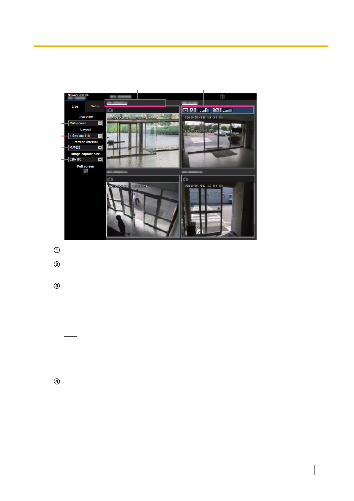
1.1.3 Monitor images from multiple cameras
Images from multiple cameras can be displayed on a multi-screen. Images from 4, 9, and up to 16 cameras
can be displayed simultaneously. To display images on a multi-screen, it is necessary to register cameras in
advance. 4 cameras can be registered as a group and up to 4 groups (16 cameras) can be registered.
(®page 155)
IMPORTANT
• When video is displayed in 4 screens and 9 screens, the video and audio may cut out because the
transmission volume of other cameras is large. In such cases, the setting of the registered cameras
needs to be changed to reduce the transmission volume.
Example of setup to reduce the transmission volume:
– Set the video transmission format to “H.265” or “H.264”.
– Set the “Transmission priority” (®page 106) of the stream to “Best effort”.
• To enable the audio for multi-screen, the audio must be enabled for the camera.
• When 16 screens are used for the display, only still images (JPEG) can be refreshed.
Note
• Multi-screen can be used to display JPEG images, and H.265 (or H.264) images. If other cameras
support audio, audio is also output.
• When displaying the multi-screen, adjust the volume.
• For further information about “Network Camera Recorder with Viewer Software Lite”, which is suited
to viewing images from several cameras, refer to our website
(https://security.panasonic.com/support/info/ <Control No.: C0301>).
• When you have registered a camera with the authentication function enabled, enter the user name and
password of the “Administrator” for the registered camera in the “Authentication dialog”.
Refer to the Panasonic support website below for information about the terms and conditions for use
of multi-screen.
https://security.panasonic.com/support/info/ <Control No.: C0302>
18 Operating Instructions
Page 19
A
B
F
C
D
E
G
1 Operations
1. From the “Live view” pull-down menu in the “Live” page, select “Multi-screen”.
→ Images from the registered cameras will be displayed on a selected multi-screen (screen can be split
up to 16 areas). The following are instructions when displaying on a 4-split screen.
“Live view” pull-down menu
Select the image displayed in the main area.
[Layout] pull-down menu
Select from the pull-down menu to display images from cameras in multi-screens of 4 to 9 or even 16
screens.
[Refresh interval] pull-down menu
Select from the pull-down menu and switch between video (H.265/H.264/MJPEG) and still images
(JPEG).
For still images (JPEG), select the refresh interval (Refresh interval : 1s/Refresh interval : 3s/Refresh
interval : 5s/Refresh interval : 10s/Refresh interval : 30s/Refresh interval : 60s) for camera images.
When the 16 screen layout is used, Refresh interval : 1s cannot be selected.
Note
• When “On” is selected for “Stream(1)”, “H.265” or “H.264” is selectable.
• When “H.265” is selected, H.264 or MJPEG image may be displayed depending on the camera
to be connected.
• When “H.264” is selected, H.265 or MJPEG image may be displayed depending on the camera
to be connected.
[Image capture size] pull-down menu
Select the image capture size from the pull-down menu to change it.
When you select “4 Screens” in the [Layout] pull-down menu, the image capture size of the camera
changes.
• When the aspect ratio is 4:3:
Switching between QVGA (default) and VGA
• When the aspect ratio is 16:9:
Switching between 320´180 (default) and 640´360
Operating Instructions 19
Page 20

1 Operations
Note
Full screen display
If you press the full screen button, the display of the camera image will be maximized. If you click the
(reset) button in the full screen display, the display size will be reset to original size.
Camera title
If you click the camera title, live images from the corresponding camera will be displayed on the
“Live” page of the newly opened window.
Camera control bar
Can be used to get snap shot of JPEG images or to adjust the PC mic input/output volume (mic input
or audio output).
• The frame rate may drop depending on the network environment and number of accessing users.
• If the image capture size specified for JPEG cannot be obtained, a JPEG image with an image
capture size that could be obtained is displayed. Therefore, when JPEG images obtained with snap
shot are displayed on a PC, the displayed image size may differ from the captured sized.
• When a video (H.265/ H.264/ MJPEG) is selected from the [Refresh interval] pull-down menu, a
different video from the setting may be displayed subject to the connected camera settings.
20 Operating Instructions
Page 21
A
B
F
C
E
D
G
1 Operations
1.2 Monitor images on a cellular phone/mobile terminal
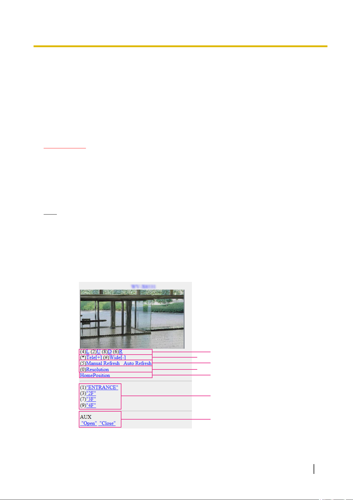
1.2.1 Monitor images on a cellular phone
It is possible to connect to the camera using a cellular phone via the Internet and monitor images (JPEG only)
from the camera on the screen of the cellular phone. It is also possible to refresh images to display the latest
image.
IMPORTANT
• When the authentication window is displayed, enter the user name and password.
To enhance the security, it is recommended to change the password periodically. (®page 182)
• If the cellular phone in use is not compatible with UTF-8 encode, it is impossible to display the screen
correctly.
• When “VGA”, “QVGA”, “640x360”, or “320x180” is not selected for either one of “JPEG(1)”,
“JPEG(2)”, or “JPEG(3)” of [JPEG] on the [Image] tab, images cannot be viewed from cellular phones.
• Audio is not supported for cellular phones.
Note
• It is necessary to configure the network settings of the cellular phone in advance to connect to the
Internet and monitor images from the camera. (®page 193)
• When “Auto” is selected for “Menu language”, the screen is displayed in English. If you want the screen
to be displayed in Japanese or Chinese, select “Japanese” or “Chinese” for “Menu language”.
(®page 71)
1. Access to “http://IP address/mobile”
cellular phone.
→ Images from the camera will be displayed.
*1
or “http://Host name registered in the DDNS server/mobile” using a
Operating Instructions 21
Page 22

1 Operations
Pan/Tilt
Controls the camera direction. The camera will pan or tilt to each direction by pressing the
corresponding dial key.
Zoom display
It is possible to perform zooming operations of the camera by pressing “*” or “#”.
Refresh control
Press the dial key “5” or the [Manual Refresh] button to refresh the camera images.
Press the [Auto Refresh] button to refresh the images from the camera in 5-second intervals.
When the dial key “5” or the [Manual Refresh] button is pressed again, the refresh mode of the camera
will return to manual refresh.
IMPORTANT
• Transmission will be periodically performed when “Auto Refresh” is selected for the camera
image. Confirm the contract plan of the cellular phone in use before using this function.
• Depending on the cellular phone in use, “Auto Refresh” may be unavailable.
Resolution control
Changes the image capture size by pressing the dial key “0”.
• Image in the aspect ratio of “4:3”: Changes the image capture size between 320x240 (default) and
640x480.
• Image in the aspect ratio of “16:9”: Changes the image capture size between 320x180 (default)
and 640x360.
Home position
The camera will move to the home position. (®Page 111)
Home position will be displayed only when home position is set.
Preset
The camera images will be displayed in a preset direction when a dial key on each window is pressed.
(The dial key numbers are not displayed for Preset No. 5 or greater. Only preset IDs will be displayed.)
(®Page 128)
AUX control
Controls the AUX terminal. These buttons will be displayed only when “AUX output” is selected for
“Terminal 3” on the setup menu. (®page 56)
Note
• Some cellular phones cannot change the image capture size even when resolution is changed by
resolution control.
• Depending on the image capture size selected for “JPEG(1)”, “JPEG(2)”, or “JPEG(3)”, “Resolution”
may not be able to be used.
• When the HTTP port number is changed from “80”, enter “http://IP address: (colon) + port number/
mobile”*1 in the address box of the browser. When using the DDNS function, access to “http://Host
name registered in the DDNS server: (colon) + port number/mobile”.
• When “HTTPS” is selected for “HTTPS” - “Connection” on the [Advanced] tab of the “Network” page,
enter as follows.
“https://IP address: (colon) + port number/mobile” or “https://Host name registered in the DDNS server:
(colon) + port number/mobile”
• When the authentication window is displayed, enter the user name of an administrator or user and
password. Depending on the cellular phone in use, password entry may be required each time the
screen is switched.
• It is impossible to send and receive audio using a mobile terminal.
• Depending on the cellular phone in use, larger size images may not be displayed. In this case, selecting
a setting close to the lowest quality setting for “Image quality setting” of “JPEG” (®page 103) may
sometimes solve this problem.
• Depending on the cellular phone in use or its contract plan, it may be impossible to access.
22 Operating Instructions
Page 23
C
D
B
A
1 Operations
• The operations menu displayed on the mobile telephone screen may not be displayed depending on
the user rights and access level of the accessing user. To display the operations menu, it is necessary
to set the user rights and access level (“User auth.” in “User mng.”). (®page 182)
*1
IP address is the global WAN IP address of the router that can be accessed via the Internet.
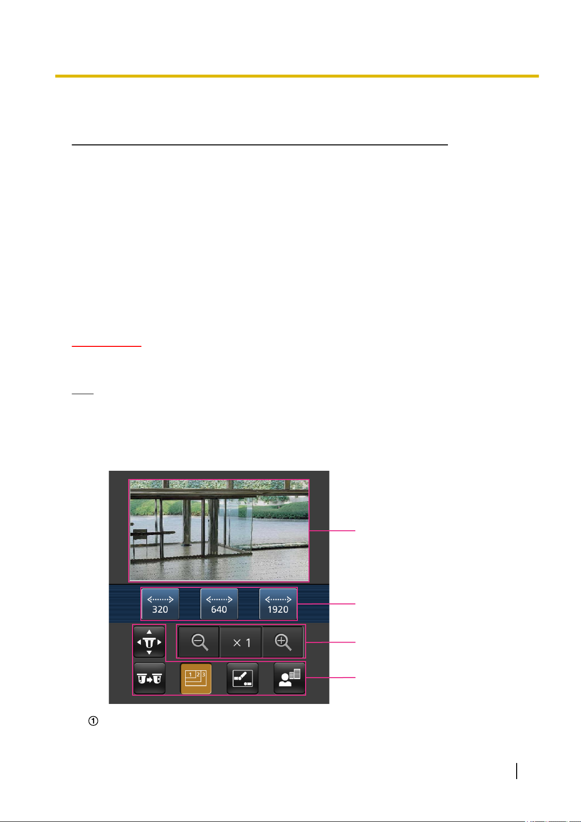
1.2.2 Monitor images on a mobile terminal (including smartphones)
It is possible to connect to the camera using a mobile terminal via the Internet and monitor images (MJPEG
or JPEG) from the camera on the screen of the mobile terminal. It is also possible to refresh images to display
the latest image.
The compatible mobile terminals are shown as follows. (As of April, 2019)
– iPad, iPhone (iOS 4.2.1 or later)
– Android™ mobile terminals
When an Android terminal is used, an MJPEG format image is displayed by the Firefox® browser, and a JPEG
format image is displayed by the standard browser.
IMPORTANT
• When the authentication window is displayed, enter the user name and password.
To enhance the security, it is recommended to change the password periodically. (®page 182)
Note
• It is necessary to configure the network settings of the mobile terminal in advance to connect to the
Internet and monitor images from the camera. (®page 193)
1. Access to “http://IP address/cam”
mobile terminal.
*1
or “http://Host name registered in the DDNS server/cam”*2 using a
→ Images from the camera will be displayed.
Live images area
Displays images from the camera.
Operating Instructions 23
Page 24
C DB
E
A
F
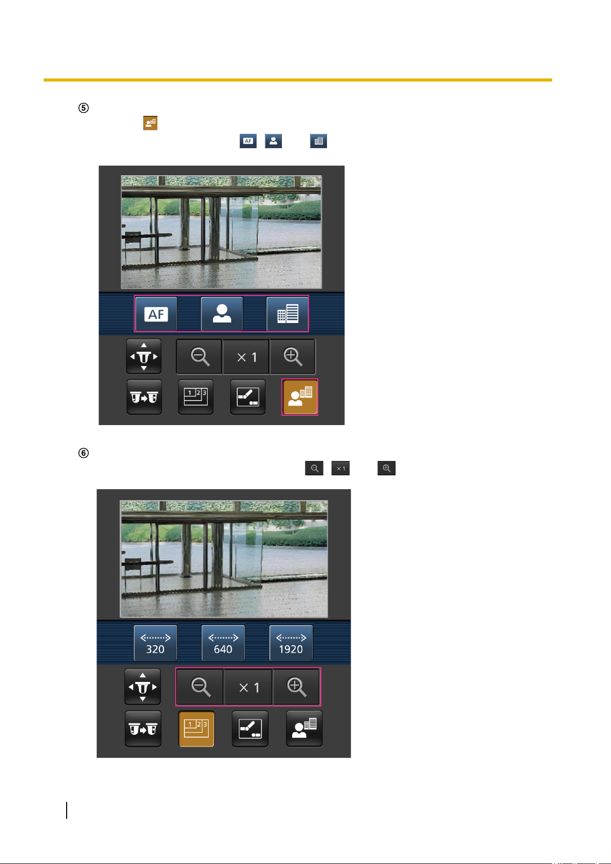
1 Operations
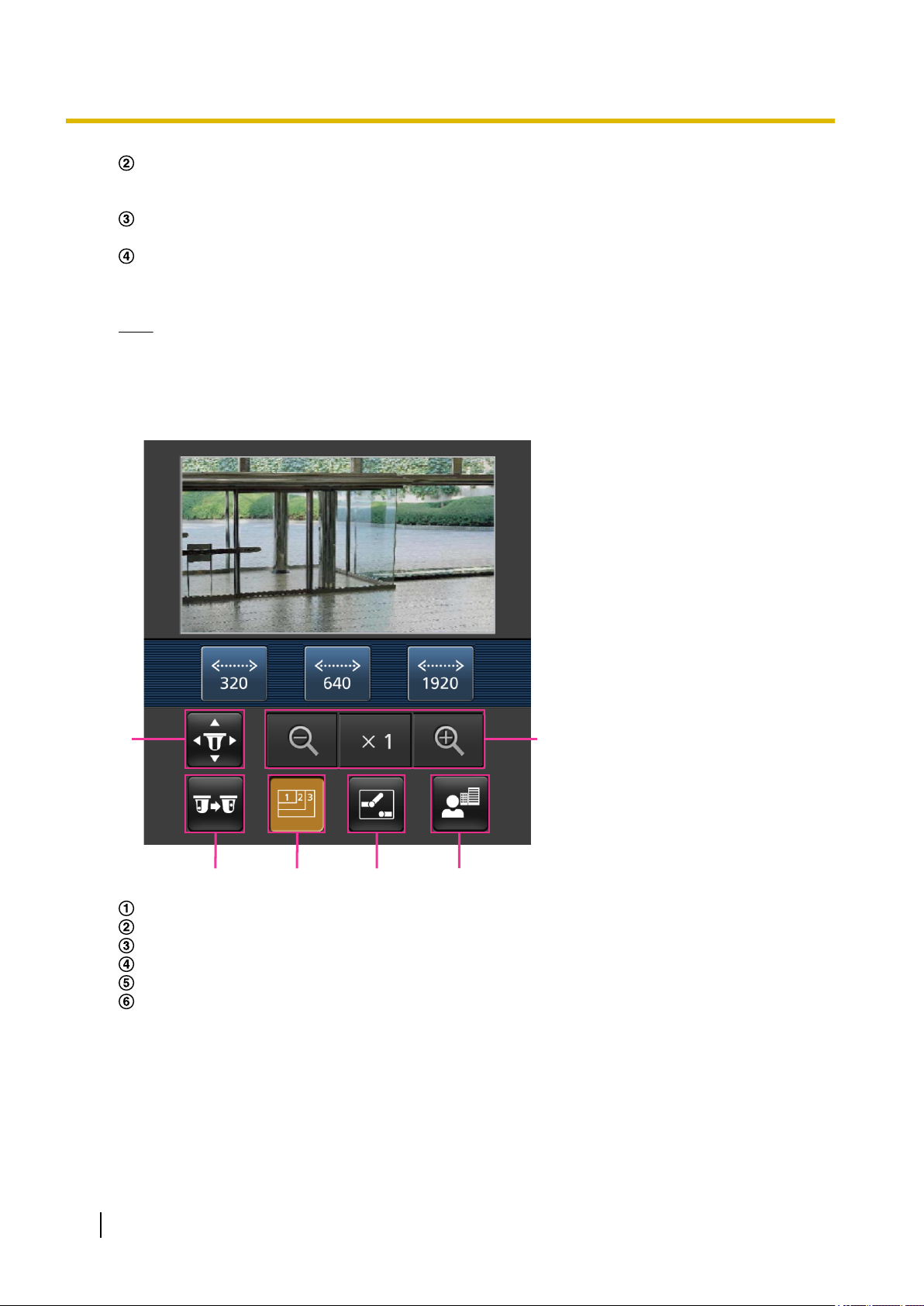
Operation buttons area
When functions are selected in the function selection area D, buttons to operate those functions are
displayed.
Zoom operation area
Buttons to operate the zoom are displayed.
Function selection area
When functions that can be operated are selected, operation buttons are displayed in the operation
buttons area B.
Note
• The operations button displayed on the mobile terminal screen may not be available depending on
the user rights and access level of the accessing user. To display the operations button, it is
necessary to set the user rights and access level (“User auth.” in “User mng.”). (®page 182)
2. Click the button of the function that you want to operate.
Pan/Tilt
Preset
Resolution control
AUX control
Focus display
Zoom display
Each function is explained below.
24 Operating Instructions
Page 25
1 Operations
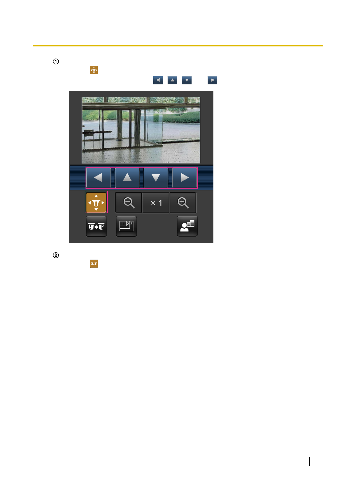
Pan/Tilt
Press the button to display the buttons used to operate pan/tilt on the screen. The pan/tilt can be
adjusted in each direction with the , , , and buttons.
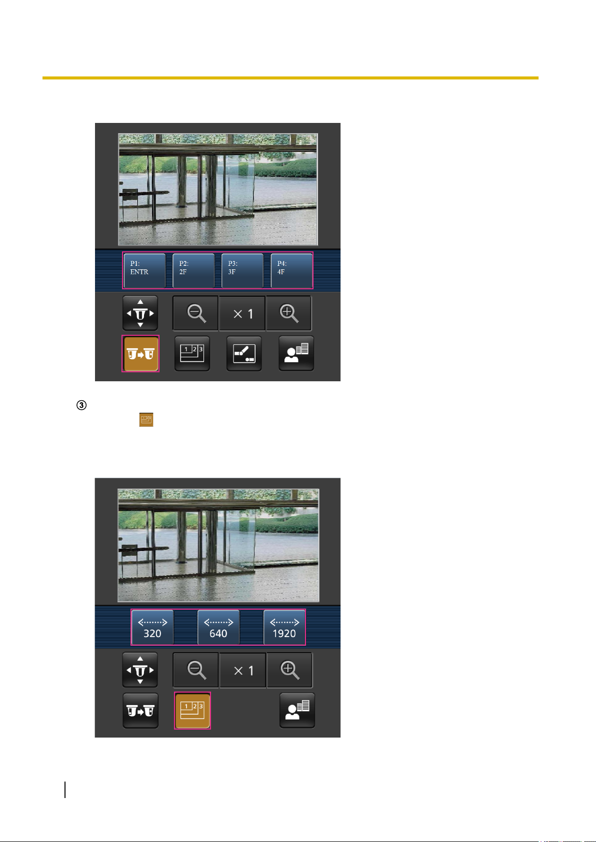
Preset
Press the button to display the buttons used to select the preset position on the screen. Camera
images are displayed of the registered preset camera directions according to the preset numbers
selected from the buttons.
• Only position numbers 1-4 for the preset positions are displayed.
• Only registered preset positions are displayed. Unregistered preset positions are not displayed.
Operating Instructions 25
Page 26
1 Operations
Resolution control
Press the button to display the buttons used to select the resolution on the screen. The resolution
can be changed by selecting a resolution setting from the buttons.
Images are displayed in the image capture size selected in “JPEG(1)”, “JPEG(2)”, or “JPEG(3)” of
[JPEG] on the [Image] tab.
26 Operating Instructions
Page 27
1 Operations
AUX control
Press the button to display the buttons used to operate the AUX output on the screen. The AUX
output terminals can be controlled with the and buttons.
This function is only displayed when [Terminal 3] is set to [AUX output] on the settings menu.
(®Page 57)
Operating Instructions 27
Page 28
1 Operations
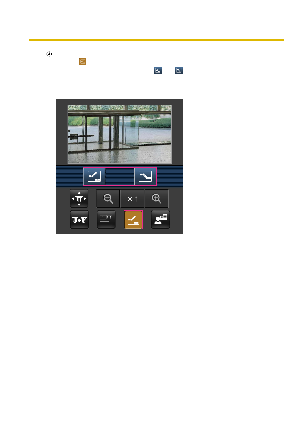
Focus display
Press the button to display the buttons used to operate the focus on the screen. The camera’s
focus can be operated with the , , and buttons.
Zoom display
The camera’s zoom can be operated with the , , and buttons.
28 Operating Instructions
Page 29

1 Operations
Note
• You can change the image size displayed on the mobile terminal by accessing the following addresses.
– Large display: http://IP address/cam/dl
– Medium display: http://IP address/cam/dm
– Small display: http://IP address/cam/ds
• When the resolution is changed by the resolution control, the displayed resolution changes but the
image size remains the same.
• When the HTTP port number is changed from “80”, enter “http://IP address: (colon) + port number/
cam”*1 in the address box of the browser. When using the DDNS function, access to “http://Host name
registered in the DDNS server: (colon) + port number/cam”*2.
• When “HTTPS” is selected for “HTTPS” - “Connection” on the [Advanced] tab of the “Network” page,
enter as follows.
“https://IP address: (colon) + port number/cam” or “https://Host name registered in the DDNS server:
(colon) + port number/cam”
• When the authentication window is displayed, enter the user name of an administrator or user and
password. Depending on the mobile terminal in use, password entry may be required each time the
screen is switched.
• It is impossible to send and receive audio using a mobile terminal.
• Depending on the mobile terminal in use, larger size images may not be displayed. In this case,
selecting a setting close to the lowest quality setting for “Image quality setting” of “JPEG” (®page
103) may sometimes solve this problem.
• Depending on the mobile terminal in use or its contract plan, it may be impossible to access.
*1
IP address is the global WAN IP address of the router that can be accessed via the Internet. However, when accessing the same
LAN as the camera with a wireless compatible mobile terminal, the IP address is the local IP address.
*2
Only when accessing the camera via the Internet.
Operating Instructions 29
Page 30
1 Operations
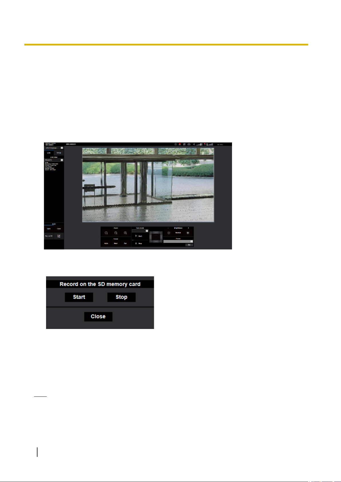
1.3 Record images on the SD memory card manually
Images displayed on the “Live” page can be recorded on the SD memory card manually. This button is operable
only when “Manual” is selected for “Save trigger” on the [SD memory card] tab on the “Basic” page of the setup
menu. (®page 84)
It is possible to select “JPEG(1)”, “JPEG(2)”, “JPEG(3)”, “Stream(1)”, “Stream(2)”, “Stream(3)”, or
“Stream(4)” on “Recording format” of the setup menu. (®page 83) When “JPEG” is selected for “Recording
format”, still image data are recorded. When “Stream(1)”, “Stream(2)”, “Stream(3)”, or “Stream(4)” is selected,
video data are recorded.
Images recorded on the SD memory card can be copied onto the PC. (®page 95)
1. Display the “Live” page. (®page 9)
2. Click the [Rec. on SD] button.
→ The SD recording window will open.
3. Click the [Start] button to start recording images on the SD memory card. The SD recording status indicator
will light red (®page 12) while images are being recorded on the SD memory card.
The image saving interval can be configured on the [SD memory card] tab of the “Basic” page.
(®page 79)
4. Click the [Stop] button to stop saving images on the SD memory card.
® The SD recording status indicator will turn off.
5. Click the [Close] button to close the window.
Note
• Image data saved on Drive B can be obtained by executing “Access img.” on the [SD memory card]
tab and logging in from the user authentication window (®page 95).
The destination to save image data is a fixed directory on Drive B (®page 278).
30 Operating Instructions
Page 31

1 Operations
• When the [Start] button is clicked immediately after the [Stop] button is clicked, saving of images may
not start. In this case, click the [Start] button again.
Operating Instructions 31
Page 32

1 Operations
1.4 Action at an alarm occurrence
The alarm action (camera action at an alarm occurrence) will be performed when the following alarms occur.
1.4.1 Alarm type
• Terminal alarm: When connecting an alarm device such as a sensor to the alarm input terminal of the
camera, the alarm action will be performed when the connected alarm device is activated.
• VMD alarm: When motion is detected in the set VMD area, the alarm action will be performed.
*VMD stands for “Video Motion Detection”.
• Command alarm: When a Panasonic alarm protocol is received from the connected device via a network,
the alarm action will be performed.
• Auto track alarm: According to the conditions set in advance, the alarm action will be performed in the
auto tracking operations.
• Audio detection alarm: When the configured audio detection level is exceeded, the alarm action will be
performed.
1.4.2 Action at an alarm occurrence
Display the alarm occurrence indication button on the “Live” page
The alarm occurrence indication button will be displayed on the “Live” page at an alarm occurrence.
(®page 12)
IMPORTANT
• When “Polling(30s)” is selected for “Status update mode” (®page 71), the Alarm occurrence
indication button will be refreshed in 30-second intervals. For this reason, it may take a maximum of
30 seconds until the alarm occurrence indication button is displayed on the “Live” page at an alarm
occurrence.
Notify of alarm occurrences to the device connected to the output terminal
It is possible to output signals from the output terminal of the camera and sound the buzzer when an alarm
occurs. The settings for the alarm output can be configured in the [Alarm] tab of the “Alarm” page.
(®page 159)
Save images on the SD memory card
When an alarm occurs, images (JPEG/H.265/H.264) will be saved on the SD memory card. The settings to
save images on the SD memory card can be configured on the [SD memory card] tab (®page 79) of the
“Basic” page and the [Alarm] tab of the “Alarm” page. (®page 161)
Transmit an image onto a server automatically
An alarm image can be transmitted at an alarm occurrence to the server designated in advance. The settings
required to transmit an alarm image to a server can be configured in the “Alarm image” section on the
[Alarm] tab of the “Alarm” page (®page 161) and the [Advanced] tab of the “Network” page (®page 203).
32 Operating Instructions
Page 33

1 Operations
Notify of alarm occurrences by E-mail
Alarm E-mail (alarm occurrence notification) can be sent at an alarm occurrence to the E-mail addresses
registered in advance. Up to 4 addresses can be registered as recipients of the alarm E-mail. An alarm image
(still picture) can be sent with the alarm E-mail as an attached file. The settings for alarm E-mail can be
configured in the “Alarm E-mail notification” section on the [Alarm] tab of the “Alarm” page (®page 161) and
the [Advanced] tab of the “Network” page (®page 198).
Notify of alarm occurrences to the designated addresses (Panasonic alarm
protocol notification)
This function is available only when a Panasonic device, such as the network disk recorder, is connected to
the system. When “On” is selected for “Panasonic alarm protocol”, the connected Panasonic device will be
notified that the camera is in the alarm state. The settings for Panasonic alarm protocol can be configured in
the “Panasonic alarm protocol notification” section of the [Notification] tab of the “Alarm” page. (®page 178)
Notify of alarm occurrences to the designated HTTP server (HTTP alarm
notification)
Alarm occurrence notifications can be sent at an alarm occurrence to the HTTP servers registered in advance.
Up to 5 HTTP servers can be registered as recipients of alarm notifications. The URL sent to HTTP servers
with alarm notifications can be specified. The settings for HTTP alarm notification can be configured on the
[Notification] tab of the “Alarm” page. (®page 180)
Operating Instructions 33
Page 34

1 Operations
1.5 Transmit images onto an FTP server
Images can be transmitted to an FTP server. By configuring the following settings, transmission of images
captured at an alarm occurrence or captured at a designated interval to an FTP server will become available.
IMPORTANT
• When using this function, set the user name and the password to access the FTP server to restrict
users who can log into the FTP server.
1.5.1 Transmit an alarm image at an alarm occurrence (Alarm image transmission)
An alarm image can be transmitted at an alarm occurrence to the FTP server. To transmit alarm images to an
FTP server, it is necessary to configure the settings in advance.
FTP server settings and settings relating to alarm image transmission can be configured in the “FTP” section
of the [Advanced] tab of the “Network” page. (®page 203) Settings can also be configured from the “Alarm
image FTP transmission” settings of “Camera action on alarm” on the [Alarm] tab of the “Alarm” page.
(®page 161)
Note
• Depending on the network traffic, the number of the transmitted images may not reach the set number
of images to be transmitted.
• Alarm images failed to be transmitted to the FTP server at an alarm occurrence will not be saved on
the SD memory card. However, images that fail to be transmitted with the FTP periodic image
transmission will be saved.
When “On” is selected for both the alarm image transmission function and the FTP periodic image
transmission function, the alarm image transmission function will be given priority over the FTP periodic
image transmission function. Also, when “On” is selected for the “FTP transmission retry” FTP setting
(®page 204), alarm images will be retransmitted if there is an FTP transmission failure. Therefore, if
there is continuous retransmission due to network problems or other factors, periodic transmission will
not be performed and images that fail to be transmitted with the FTP periodic image transmission will
not be saved to an SD memory card.
1.5.2 Transmit images at a designated interval or period (FTP periodic image transmission)
Images can be transmitted at a designated interval or period. To transmit images at a designated interval or
period, it is necessary to configure the settings in advance.
FTP server settings and settings relating to FTP periodic transmission image transmission can be configured
in the “FTP” section of the [Advanced] tab of the “Network” page. (®page 203)
When using FTP periodic image transmission, it is necessary to configure the schedule settings of FTP periodic
image transmission on the [Schedule] tab of the “Schedule” page.
Configure the schedule settings of the FTP periodic image transmission on the “Schedule” page.
(®page 242)
Note
• Depending on the line speed or the traffic, images may not be transmitted at the designated interval.
• When “On” is selected for both the alarm image transmission function and the FTP periodic image
transmission function, the alarm image transmission function will be given priority over the FTP periodic
34 Operating Instructions
Page 35

1 Operations
image transmission function. Therefore, images may not be transmitted at the interval designated on
the “FTP periodic image transmission” setting.
1.5.3 Save images on the SD memory card when images fail to transmit using the FTP periodic image transmission function
Images that have failed to transmit using the FTP periodic image transmission can be saved automatically on
the SD memory card. It is possible to select a trigger to save images on the SD memory card on the [SD
memory card] tab of the “Basic” page. (®page 79)
To use the SD memory backup function featured in Panasonic network disk recorder select “Off” for “FTP
periodic image transmission” (®page 205) and “FTP periodic image transmission error” for “Save trigger” of
“Recording stream 1” (®page 84).
Note
• When “On” is selected for both the alarm image transmission function and the FTP periodic image
transmission function, the alarm image transmission function will be given priority over the FTP periodic
image transmission function. Also, when “On” is selected for the “FTP transmission retry” FTP setting
(®page 203), alarm images will be retransmitted if there is an FTP transmission failure. Therefore, if
there is continuous retransmission due to network problems or other factors, periodic transmission will
not be performed and images that fail to be transmitted with the FTP periodic image transmission will
not be saved to an SD memory card.
IMPORTANT
• We make no guarantee for any damages of files on the SD memory card incurred by malfunction or
error occurrence in files saved in the SD memory card regardless of what the cause may be.
Operating Instructions 35
Page 36

1 Operations
1.6 Display the log list
The history of various logs will be displayed in list form.
• Alarm log: Logs of the alarm occurrences such as time and date of the alarm occurrences, the image
recording period and the alarm type will be displayed.
• Manual/Schedule log: Logs filed when images have been recorded manually or during the period of the
schedule, and the image recording period will be displayed.
• FTP trans. error log: Logs filed when the FTP periodic image transmission function has failed will be
displayed.
1. Display the “Live” page.
36 Operating Instructions
Page 37

2. Click the [Log] button.
A
B
C
D
E
F
→ The log list will be displayed in a newly opened window (log list window).
1 Operations
IMPORTANT
• Only a single user can operate the log list window. Other users cannot access the log list window.
Time
Displays the time period of the data recorded on the SD memory card.
Recording stream
Select the recording stream that you want to display logs for.
• Stream 1: The logs recorded by “Recording stream 1” on the [SD memory card] tab will be displayed.
• Stream 2: The logs recorded by “Recording stream 2” on the [SD memory card] tab will be displayed.
Event
Select a log type to display on the log list.
• All: All logs will be displayed.
• Select: Only the logs of the selected log type will be displayed.
– Alarm log: The log when an alarm is detected will be displayed.
– Manual/Schedule log: Manual and Schedule logs will be displayed.
– FTP trans. error log: Logs filed when the FTP periodic image transmission function has failed will
be displayed.
• Default: All
Operating Instructions 37
Page 38

1 Operations
Note
Recording time
Configure the time period of logs displayed on the log list.
• From: Configure the starting period of logs displayed on the log list.
• To: Configure the ending period of logs displayed on the log list when “First recording” or “Date/time”
[Search] button
Searches for logs according to the conditions specified in “Event” and “Recording time”.
The search result will be displayed on the log list.
Log list
Displays the log search results.
You can play back recorded data by clicking on the time or duration of the recorded data displayed under
[Time & date] and [Duration].
• When “Stream 1” is selected for “Recording stream” and either “JPEG(1)”, “JPEG(2)”, or
“JPEG(3)” is selected for “Stream 1”, the FTP trans. error log will be displayed.
– First recording: Displays from the first log recorded on the SD memory card.
– Today: Displays the logs recorded today.
– Yesterday: Displays the logs recorded from yesterday to the present day.
– Last 7 days: Displays the logs recorded from 6 days ago to the present day.
– Last 30 days: Displays the logs recorded from 29 days ago to the present day.
– Date/time: Displays the logs recorded from the entered date and time on “Date/time” box.
is selected for “From”.
– Last recording: Displays until the last log recorded on the SD memory card.
– Date/time: Displays the logs recorded until the entered date and time on “Date/time” box.
•
(Top) button: Click this button to display the log listed at the top.
• (Prev. page) button: Click this button to display the previous page of the log list.
• (Next page) button: Click this button to display the next page of the log list.
•
(Last) button: Click this button to display the log listed at the bottom.
• [Time & date]: Time and date when each log has been recorded will be displayed.
Note
• When “Off” is selected for “Time display format”, the alarm occurrence times are displayed in
24 hour time format.
• The recording timing of logs is as follows.
– Alarm log: Alarm occurrence time and date will be filed as a log.
– Manual/Schedule log: Time and date when recording of images onto the SD memory card
started manually or during the period of the schedule will be filed as a log. When images
are recorded sequentially, if “JPEG” is selected for “Recording format”, logs will be filed on
the hour every hour (12:00, 1:00, 2:00, etc.). If “Stream” is selected for “Recording
format”, logs will be filed every hour from the time when recording starts.
– FTP trans. error log: Logs will be filed every one hour.
• [Duration]: Displays the period of time that the data has been recorded on the SD memory card.
Note
• The difference between the recording end time and recording start time of the image is
calculated by rounding off to the nearest tenth of a second. For this reason, when only 1 JPEG
image is saved, 00:00:00 is displayed for the duration.
• [Event]: The event type will be displayed.
– MN/SC: Log by “Manual/Schedule”
38 Operating Instructions
Page 39

1 Operations
– TRM1: Alarm by alarm input to Terminal 1
– TRM2: Alarm by alarm input to Terminal 2
– TRM3: Alarm by alarm input to Terminal 3
– VMD: Alarm by VMD alarm
– COM: Alarm by command alarm
– AT: Alarm detected by auto track alarm
– AUD: Alarm by audio detection alarm
– FTP: Logs saved from FTP periodic image transmission errors
• [SD memory card]: Available capacity and the original capacity of the SD memory card will be
displayed.
• (Delete) button: Deletes log lists from all pages. When logs are searched for, only the searched
logs are deleted. Images associated with deleted logs will also be deleted.
IMPORTANT
• If there are many recorded data files on the SD memory card, it may take time to delete all of
them. (For example, when the total size is 1 GB, it may take about 1 hour to delete the files.)
In this case, format the SD memory card. However, please note that formatting will delete all
of the files on the SD memory card.
• In the process of the deletion, “Alarm” and “Manual/Schedule” cannot be operated.
• Do not turn off the power of the camera until the deletion is complete. When the power of the
camera is turned off in the process of the deletion, some images may remain on the SD memory
card. In this case, click the
button on the same log list window used to delete the logs.
• (Download) button: Click this button to download all logs of the selected log list onto the PC.
Note
• The following settings may be required.
Open Internet Explorer, click [Tools] ® [Internet Options] ® [Security] ® [Trusted Sites] ®
[Sites]. Register the camera address on [Website] of the displayed trusted windows.
After registration, close the web browser, and then access the camera again.
• Up to 50,000 logs will be downloaded to the SD memory card. When more than 50,000 logs
are filed, the older logs will be overwritten by the newer logs. In this case, the oldest log is the
first to be overwritten.
If there are many logs, it may take time to download the logs.
•
(Close) button: Click this button to close the log list window.
Operating Instructions 39
Page 40

A
1 Operations
1.7 Playback of images on the SD memory card
When clicking a time and date listed on the log list window, the “Live” page will turn to the “Playback” page.
When images associated with the clicked time and date are on the SD memory card, the first image of them
will be displayed.
The display format varies depending on the “Recording format” of the SD memory card.
IMPORTANT
• Refresh interval of images may become slow during playback or download.
• When many images are saved on the SD memory card, it may take time to display images on the
“Playback” page.
• When the aspect ratio is “4:3”, images will be displayed in VGA size on the “Playback” page regardless
of the image capture size of the images saved on the SD memory card. When the aspect ratio is
“16:9”, images will be displayed in “640x360” on the “Playback” page regardless of the image capture
size of the images saved on the SD memory card. Therefore, images may look coarse on the
“Playback” page.
• When playing images by selecting an FTP error log on the log list, images may not be played in order
of images recorded on the SD memory card if they have been recorded on the SD memory card with
selected value for the “Transmission interval” setting of “FTP periodic image transmission” on the
[Advanced] tab is “1min” or less.
• The playback refresh interval may become slower when recording data to the SD memory card.
1.7.1 Playback “JPEG(1)”/“JPEG(2)”/“JPEG(3)” images saved to the SD memory card
Number of images
When clicking a time and date listed on the log list window, total number of images associated with the
clicked time and date, and the number of the currently displayed image will be displayed.
40 Operating Instructions
Page 41

1 Operations
Note
• Enter the desired number of image and press the [Enter] key on the keyboard. The image of the
designated number will be displayed.
(REW) button
Each time the button is clicked, the playback speed will change.
When the button or the button is clicked during fast reverse playback, playback speed will return to
the normal playback speed.
(REV PLAY) button
Images will be played in reverse sequential order.
(PLAY) button
When this button is clicked, images will be played in sequential order.
(FF) button
Each time the button is clicked, the playback speed will change.
When the button or the button is clicked during fast playback, playback speed will return to the normal
playback speed.
(TOP) button
The first image will be displayed.
(PREV. IMAGE) button
The previous frame will be displayed and paused when this button is clicked during playback.
Each time this button is clicked during pausing, the frame previous to the currently displayed frame will be
displayed.
Note
• When the mouse button is held down while the mouse pointer is on this button, the image number will
be decreased.
When the mouse button is released, the decreasing of the image number will stop and the image
corresponding to the currently displayed number will be displayed.
(PAUSE) button
Playback will be paused when this button is clicked during playback.
Playback will resume when this button is clicked during pausing.
(STOP) button
Playback will stop and the “Playback” window will turn to the “Live” page.
(NEXT IMAGE) button
The next frame will be displayed and paused when this button is clicked during playback.
Each time this button is clicked during pausing, the frame next to the currently displayed frame will be displayed.
Operating Instructions 41
Page 42

1 Operations
Note
• When the mouse button is held down while the mouse pointer is on this button, the image number will
be increased.
When the mouse button is released, the increment of the image number will stop and the image number
displayed at the moment when the mouse button is released will be displayed.
(LAST) button
The last image will be displayed.
(Start) button
The selected image will be downloaded onto the PC. Before downloading images, designate the destination
directory in advance. (®page 97)
The following window will be displayed when the button is clicked.
Select the image to be downloaded, and then click the [OK] button.
• All: All images saved at the selected time and date will be downloaded.
• Current image: Only the currently displayed image will be downloaded.
• Download range: Images in the specified range will be downloaded.
Note
• When the [Cancel] button is clicked in the process of the download, the download will be canceled. In
this case, images already downloaded before clicking the [Cancel] button will be saved on the PC.
(Browse) button
When successfully logged in after the user authentication process, a folder on the SD memory card in which
images are saved will be displayed. (®page 95)
Note
• FTP access to camera must be allowed.
Select “Allow” for “FTP access to camera” on the [Network] tab.
• There is a possibility that authentication information (user names, passwords) will be leaked when
accessing the camera from a PC.
When loading images from the SD memory card, it is recommended to select “Digest” for
[Authentication method] in the [User auth.] tab, or download the playback image of the SD memory
card after encrypting access using the HTTPS function.
42 Operating Instructions
Page 43

A
1 Operations
1.7.2 Playback “Stream(1)”/“Stream(2)”/“Stream(3)”/“Stream(4)” images saved to the SD memory card
IMPORTANT
• Depending on the network environment, download of video data may fail. If downloading failed while
playing images, you may be able to download images after stopping the currently played images and
starting the download again.
• Depending on the network environment and status of the camera, you may not be able to operate each
operation on this screen consecutively.
Slider bar
By operating the slider bar, you can select where to start playing images from. The slider bar can only be
used before playing images, or when playing is paused or stopped.
(PAUSE) button
Playback will be paused when this button is clicked during playback.
(PLAY) button
When this button is clicked, recorded data will be played.
Note
• If audio is recorded, it can be played back, but the image and audio will not be synchronized. Therefore,
images and audio may not always match. When data is being recorded to the SD memory card, audio
may sound as if it is cutting out and the audio quality may be reduced.
• When recorded audio is played back, the refresh interval of live images and playback may become
slow.
• Recorded audio is not played back when “Off” or “Interactive(Half-duplex)” is selected for “Audio
transmission mode” on the [Audio] tab of the “Image/Audio” page.
Operating Instructions 43
Page 44

1 Operations
(FF) button
Each time this button is clicked, the playback speed will change. When the button is clicked during fast
playback, playback speed will return to the normal playback speed.
Note
• The maximum speed of the fast playback varies depending on the setting of “Bit rate” of the stream
selected with “Recording format” of the SD memory card.
• Recorded audio will not be played back during fast playback.
(5s backward) button
Each time this button is clicked, the recorded data goes back by 5 seconds and starts playing.
(5s forward) button
Each time this button is clicked, the recorded data goes forward by 5 seconds and starts playing.
(STOP) button
Playback will stop and the “Playback” window will turn to the “Live” page.
[Time & date]
Time and date when each log has been recorded will be displayed.
[Duration]
Displays the period of time that the data has been recorded on the SD memory card.
[Event]
The event type will be displayed.
• MN/SC: Log by “Manual/Schedule”
• TRM1: Alarm by alarm input to Terminal 1
• TRM2: Alarm by alarm input to Terminal 2
• TRM3: Alarm by alarm input to Terminal 3
• VMD: Alarm by VMD alarm
• COM: Alarm by command alarm
• AT: Alarm detected by auto track alarm
• AUD: Alarm by audio detection alarm
(Start) button
The selected image will be downloaded onto the PC.
Before downloading images, designate the destination directory in advance. (®page 97)
The message window will be displayed to ask if it is OK to start download when the
the [OK] button.
button is clicked. Click
Note
• The image playing screen cannot be operated while downloading. Perform operations after the
downloading is completed.
• When the [Cancel] button is clicked in the process of the download, the download will be canceled. In
this case, video data already downloaded before clicking the [Cancel] button will be saved on the PC.
• Video data are saved in the files of approx. 20 MB. When the file size of video data is more than 20
MB, two or more files will be downloaded.
44 Operating Instructions
Page 45

1 Operations
• It is possible to play back H.264 video data saved on the PC using such applications as Windows Media
Player. However, we are not liable for performance relating to these applications.
• Depending on the status of the SD memory card or Windows Media Player, H.264 video data cannot
be played back.
For information on playing back H.265 video data, refer to the following Panasonic website below.
https://security.panasonic.com/support/info/ <Control No.: C0303>
Operating Instructions 45
Page 46

2 Settings
2 Settings
2.1 About the network security
2.1.1 Equipped security functions
The following security functions are featured in this camera.
Access restrictions by the host authentication and the user authentication
It is possible to restrict users from accessing the camera by setting the host authentication and/or the user
authentication to “On”. (®page 182, page 185)
Access restrictions by changing the HTTP port
It is possible to prevent illegal access such as port scanning, etc. by changing the HTTP port number.
(®page 195)
Access encryption by the HTTPS function
It is possible to enhance the network security by encrypting the access to cameras using the HTTPS
function. (®page 216)
IMPORTANT
• Design and enhance security countermeasures to prevent leakage of information such as image data,
authentication information (user name and password), alarm E-mail information, FTP server
information, DDNS server information, etc. Perform the countermeasure such as access restriction
(using the user authentication) or access encryption (using the HTTPS function).
• After the camera is accessed by the administrator, make sure to close the browser for added security.
• Change the administrator password periodically for added security.
Note
• When user authentication (authentication error) has failed to pass 8 times within 30 seconds using the
same IP address (PC), access to the camera will be denied for a while.
46 Operating Instructions
Page 47

2.2 Display the setup menu from a PC
The settings of the camera can be configured on the setup menu.
IMPORTANT
• The setup menu is only operable by users whose access level is “1. Administrator”. Refer to
page 182 for how to configure the access level.
2.2.1 How to display the setup menu
1. Display the “Live” page. (®page 9)
2. Click the [Setup] button on the “Live” page.
→ The setup menu will be displayed. Refer to page 49 for further information about this menu.
2 Settings
Operating Instructions 47
Page 48

A B
A
B
C
D
2 Settings
2.2.2 How to operate the setup menu
Menu buttons
Setup page
1. Click the desired button in the frame on the left of the window to display the respective setup menu.
When there are tabs at the top of the “Setup” page displayed in the frame on the right of the window, click
the desired tab to display and configure the setting items relating to the name of the tab.
2. Complete each setting item displayed in the frame on the right of the window.
3. After completing each setting item, click the [Set] button to apply them.
IMPORTANT
• When there are two or more [Set], [Register], and [Execute] buttons on the page, click the respective
button to the edited setting item.
<Example>
When completing the setting items in field A, click the [Set] button (B) below field (A).
The edited settings in field A will not be applied unless the [Set] button (B) below field (A) is clicked.
In the same manner as above, click the [Set] button (D) below field C when completing the setting
items in field C.
48 Operating Instructions
Page 49

2.2.3 About the setup menu window
A
M
N
E
D
F
H
I
J
K
L
G
B
C
2 Settings
[Setup] button
Display the “Setup” page.
[Live] button
Display the “Live” page.
[Easy Setup] button
Displays the “Easy Setup” page. The “Easy Setup” page is used to set the connectivity to the Internet, as
well as to set event actions such as alarm settings and camera action on alarm. (®page 51)
[Basic] button
Displays the “Basic” page. The basic settings such as time and date and camera title, and the settings
relating to the SD memory card can be configured on the “Basic” page. (®page 71)
[Image/Audio] button
Displays the “Image/Audio” page. The settings relating to image quality, image capture size, etc. of JPEG/
H.265/H.264 camera images can be configured on the “Image/Audio” page. (®page 102)
[Multi-screen] button
Displays the “Multi-screen” page. The cameras from which images are to be displayed on a multi-screen
can be registered on the “Multi-screen” page. (®page 155)
[Alarm] button
Displays the “Alarm” page. The settings relating to alarm occurrences such as settings for the alarm action
at an alarm occurrence, the alarm occurrence notification, and the VMD area settings can be configured
on the “Alarm” page. (®page 157)
[User mng.] button
Displays the “User mng.” page. The settings relating to the authentication such as users and PCs
restrictions for accessing the camera can be configured on the “User mng.” page. (®page 182)
[Network] button
Displays the “Network” page. The network settings and the settings relating to DDNS (Dynamic DNS),
SNMP (Simple Network Management Protocol), FTP (File Transfer Protocol), the NTP server, and QoS
can be configured on the “Network” page. (®page 193)
Operating Instructions 49
Page 50

2 Settings
[Schedule] button
Displays the “Schedule” page. On the “Schedule” page, it is possible to designate time zones to allow to
activate the VMD detection function. (®page 239)
[Maintenance] button
Displays the “Maintenance” page. System log check, firmware upgrade, status check and initialization of
the setup menu can be carried out on the “Maintenance” page. (®page 246)
[Support] button
Displays the support page.
In the support page, how to access to the Panasonic support web site is described. (®Page 254)
Camera title
The title of the camera whose settings are currently being configured will be displayed.
Setup page
Pages of each setup menu will be displayed. There are tabs for some setup menus.
The bottom of the settings page has been omitted.
50 Operating Instructions
Page 51

2.3 Use Easy Setup [Easy Setup]
The “Easy Setup” page uses simple operations to set the following:
– Make the camera image available on the Internet
– Set event actions such as recording of a schedule/alarm to the SD memory card
The “Easy Setup” page consists of the [Internet] tab and [Event action] tab.
2.3.1 Configure the Internet settings [Internet]
Click the [Internet] tab of the “Easy Setup” page. (®For menu display and how to operate, refer to page 47,
page 48)
The settings relating to UPnP (Auto port forwarding), DDNS (Viewnetcam.com), and network settings for the
Internet can be configured on this page.
2 Settings
[UPnP (Auto port forwarding)]
Select “On” or “Off” to determine whether or not to use the port forwarding function of the router.
To use the auto port forwarding function, the router in use must support UPnP and the UPnP must be enabled.
• Default: Off
Note
• Due to auto port forwarding, the port number may sometimes be changed. When the number is
changed, it is necessary to change the port numbers registered in the PC and recorders, etc.
• The UPnP function is available when the camera is connected to the IPv4 network. IPv6 is not
supported.
• To check if auto port forwarding is properly configured, click the [Status] tab on the “Maintenance” page,
and check that the “Enable” is displayed for “Status” of “UPnP”. (®page 248)
When “Enable” is not displayed, refer to “Cannot access the camera via the Internet.” in
3.3 Troubleshooting.
• When the “UPnP (Auto port forwarding)” setting is changed, the “Auto port forwarding” setting under
“UPnP” on the [Advanced] tab of the “Network” page also changes to the same setting.
[Area]
Select the region where the camera is installed.
Global/Japan
Operating Instructions 51
Page 52

2 Settings
Note
• If the camera is used in Japan, select “Japan”. If the camera is used outside of Japan, select
“Global”. The “Viewnetcam.com” service that is displayed when “Global” is selected cannot be used in
Japan.
[Service]
Select “Viewnetcam.com” or “Off” to determine whether or not to use “Viewnetcam.com”.
By selecting “Viewnetcam.com” and clicking the [Set] button, the registration window for “Viewnetcam.com”
will be displayed in a newly opened window.
Follow the on-screen instructions to register with “Viewnetcam.com”.
Refer to page 235 or the “Viewnetcam.com” website (http://www.viewnetcam.com/) for further information.
• Default: Off
Note
• When the “DDNS” setting is changed, the “DDNS” setting on the [Advanced] tab of the “Network” page
also changes to the same setting.
[Recommended network setting for internet]
The recommended settings for connecting to the Internet are performed here.
By clicking the [Set] button, a dialog displaying how the following settings will change is displayed.
Click the [OK] button after checking the settings to change the settings to the displayed values.
– [Image] tab on the “Image/Audio” page
[JPEG(1)]
[Image capture size]: VGA/640x360
[JPEG(2)], [JPEG(3)]
[Image capture size]: QVGA/320x180
[Stream(1)]/[Stream(2)]/[Stream(3)]/[Stream(4)]
[Internet mode (over HTTP)]: On
[Transmission priority]: Best effort
[Max bit rate (per client)*]: 1024 kbps
[Stream(1)]
[Image capture size]: 1280x960/1280x720
[Stream(2)]
[Image capture size]: VGA/640x360
[Stream(3)], [Stream(4)]
[Image capture size]: QVGA/320x180
– [Network] tab on the “Network” page
[Common]
[Max RTP packet size]: Limited(1280byte)
[HTTP max segment size(MSS)]: Limited(1280byte)
2.3.2 Configure an event action [Event action]
Click the [Event action] tab in the “Easy Setup” page. (®For menu display and how to operate, refer to
page 47, page 48)
52 Operating Instructions
Page 53

2 Settings
The current settings are displayed here.
You can set event actions for SD schedule recording/FTP periodic image transmission/alarm detection. Once
the settings are completed in each setup menu, click the [Next] button to proceed.
The setup flow is as follows.
Note
• If you click the [Next] button, the settings in the screen will be saved.
• When “2 mega pixel [16:9](60fps mode)” is selected for “Image capture mode”, functions related to SD
memory cards are not available.
Operating Instructions 53
Page 54

2 Settings
Flow of event action setup
Event function type:
Select the trigger
according to the
purpose of setting.
Event action setup:
Configure the action
conditions selected in
the event function type
setup.
Event detailed setup:
Configure the details of
the settings in event
action setup.
Alarm
(®page 52)
Terminal/VMD/Audio detection
FTP img. trans.
(®page 60)
Settings of
image transfer
conditions
FTP settings
SD memory
recording:
JPEG/H.265/H.
264
(®page 60)
Settings of
recording
conditions
(®page 65)
SD memory
recording:
H.265/H.264
(®page 65)
Settings of
recording
conditions
Schedule
FTP periodic
image
transmission
(®page 67)
Settings of
image transfer
method
Alarm output (terminal)
E-mail settings Schedule settings
Completed Completed
54 Operating Instructions
Page 55

2 Settings
2.3.2.1 Configure the schedule/alarm (event function type setup menu)
Here, select the function type of the event.
[Trigger]
• Alarm: Select when setting the alarm detection settings.
• Schedule: Select during “SD memory recording” or “FTP periodic image transmission”.
• Default: Alarm
[SD memory card format]
To format the SD memory card, click the [Execute] button.
Once you click the [Execute] button, the “Format” confirmation screen will be displayed.
If you click the [OK] button, the formatting will start.
Once the “Format” completion screen is displayed, press the button.
IMPORTANT
• All data saved on the SD memory card will be deleted when the SD memory card is formatted.
• Do not turn off the power of the camera during formatting.
[Next] button
If you select “Alarm”, and click the [Next] button, the alarm setup menu will be displayed. (®page 56)
If you select “Schedule”, and click the [Next] button, the schedule function type setup menu will be displayed.
(®page 65)
Operating Instructions 55
Page 56

2 Settings
2.3.2.2 Alarm: Configure the terminal and VMD (alarm setup menu)
The settings relating to actions when an alarm is detected can be configured in this section.
Alarm
[Terminal 1]
Determine how to use terminal 1.
• Off: Not used.
• Alarm input(TRM1): Receives terminal alarm input.
– Close: An alarm is detected when the terminal status is changed to “On”.
– Open: An alarm is detected when the terminal status is changed to “Off”.
• Black & white input: Receives the black & white input. (When the input is set to “On”, the black & white
mode is activated)
• Auto time adjustment: Receives time setting through terminal input. When the signal is entered, if the
time difference from the hour (every hour) is less than 29 minutes, the time is adjusted to 00 minutes 00
seconds. The time is not changed in operations which reset the time under 5 seconds. If you select auto
time adjustment, the pull-down menu to select close or open is displayed.
– Close: Performs auto time adjustment when the terminal status is changed to “Close”.
– Open: Performs auto time adjustment when the terminal status is changed to “Open”.
• Default: Off
[Terminal 2]
Determine how to use terminal 2.
• Off: Not used.
• Alarm input(TRM2): Receives terminal alarm input.
– Close: An alarm is detected when the terminal status is changed to “On”.
– Open: An alarm is detected when the terminal status is changed to “Off”.
• Alarm output: Alarm output will be carried out according to the settings for “Output terminal” (®page
159).
56 Operating Instructions
Page 57

2 Settings
• Default: Off
[Terminal 3]
Determine how to use terminal 3.
• Off: Not used.
• Alarm input(TRM3): Receives terminal alarm input.
– Close: An alarm is detected when the terminal status is changed to “On”.
– Open: An alarm is detected when the terminal status is changed to “Off”.
• AUX output: AUX output is carried out. The [AUX] button will be displayed on the “Live” page.
• Default: Off
[VMD alarm]
Select an auto track alarm to be used from the following.
• On: If the VMD area is not configured, the entire region is configured. To configure the VMD area, use the
[VMD area] tab on the “Alarm” page. (®page 173)
• Off: Disables all VMD states.
• Default: Off
[Auto track alarm]
Select an auto track alarm to be used from the following.
• Off: Not used.
• On(Immediate):Alarms are continuously outputted during auto tracking. (Outputs are made at 5 second
intervals.)
• On(After alarm wait time): Alarms are outputted only once when the auto tracking is continuously
performed for a set period.
• On(In preset alarm area): While tacking, if the tracking target enters the set alarm area, an alarm is
outputted once.
• Default: Off
Note
• When “On(After alarm wait time)” is selected, it is required to set “Alarm wait time” in the auto track
setting. (®Page 136)
[Audio detection alarm]
• On: If audio detection is not configured, set audio detection to “On”. To set the sensitivity of audio detection,
set using the [Audio detection] tab on the “Alarm” page. (®page 175)
• Off: Disables audio detection.
• Default: Off
[Alarm deactivation time]
Set the duration for which detection is not to be performed after an alarm has been detected. For example, by
using this function you can prevent mail from being sent too often when the E-mail notifications are configured
to be sent to cellular phones when an alarm is detected.
5 – 600 seconds
• Default: 5s
Note
• The duration of the alarm deactivation time can be specified for each type of alarm. For example,
during the time when detections for “Terminal alarm 1” are not made, detections for “VMD alarm”
can be made.
Operating Instructions 57
Page 58

2 Settings
Camera action on alarm
[Terminal alarm 1]
Select an action to be taken when a terminal alarm 1 is detected from the following.
This setting is available when “Terminal 1” is selected for “Alarm input(TRM1)” of the [Alarm] tab.
• Off: Does not take any action even when a terminal alarm 1 is detected.
• 1-256: If a previously registered preset position is selected, when a terminal alarm 1 is detected, the camera
will move to that position.
• Auto track: When a terminal alarm 1 is detected, the camera will start the auto tracking.
• Patrol 1: When a terminal alarm 1 is detected, the camera will start the patrol.
* If “Patrol 1” is not registered, it is not displayed on the screen.
• Default: Off
[Terminal alarm 2]
Select an action to be taken when a terminal alarm 2 is detected from the following.
This setting is available when “Terminal 2” is selected for “Alarm input(TRM2)” of the [Alarm] tab.
• Off: Does not take any action even when a terminal alarm 2 is detected.
• 1-256: If a previously registered preset position is selected, when a terminal alarm 2 is detected, the camera
will move to that position.
• Auto track: When a terminal alarm 2 is detected, the camera will start the auto tracking.
• Patrol 2: When a terminal alarm 2 is detected, the camera will start the patrol.
* If “Patrol 2” is not registered, it is not displayed on the screen.
• Default: Off
[Terminal alarm 3]
Select an action to be taken when a terminal alarm 3 is detected from the following.
This setting is available when “Terminal 3” is selected for “Alarm input(TRM3)” of the [Alarm] tab.
• Off: Does not take any action even when a terminal alarm 3 is detected.
• 1-256: If a previously registered preset position is selected, when a terminal alarm 3 is detected, the camera
will move to that position.
• Auto track: When a terminal alarm 3 is detected, the camera will start the auto tracking.
• Patrol 3: When a terminal alarm 3 is detected, the camera will start the patrol.
* If “Patrol 3” is not registered, it is not displayed on the screen.
• Default: Off
[VMD alarm]
Select an action to be taken when a VMD alarm is detected from the following.
• Off: Does not take any action even when a VMD alarm is detected.
• 1-256: If a previously registered preset position is selected, when a VMD alarm is detected, the camera
will move to that position.
• Auto track: When a VMD alarm is detected, the camera will start the auto tracking.
• Patrol 1: When a VMD alarm is detected, the camera will start the patrol.
* If “Patrol 1” is not registered, it is not displayed on the screen.
• Default: Off
[Audio detection alarm]
Select an action to be taken when a sound alarm is detected from the following.
• Off: Does not take any action even when a sound alarm is detected.
• 1-256: If a previously registered preset position is selected, when a sound alarm is detected, the camera
will move to that position.
• Auto track: When a sound alarm is detected, the camera will start the auto tracking.
• Patrol 1: When a sound alarm is detected, the camera will start the patrol.
* If “Patrol 1” is not registered, it is not displayed on the screen.
58 Operating Instructions
Page 59

2 Settings
• Default: Off
[Next] button
If you click the [Next] button, the alarm function type setup menu will be displayed. (®page 59)
Note
• If you click the [Next] button, the setting items in the screen are saved.
[Back] button
If you click the [Back] button, the event function type setup menu will be displayed. (®page 55)
2.3.2.3 Alarm: Configure the alarm function type (Alarm function type setup menu)
Select the alarm function type as “FTP Transfer” or “SD memory recording”.
[Trigger]
• FTP Transfer: When an alarm occurs, performs FTP transfer of the JPEG image.
• SD memory recording: When an alarm occurs, records the image to the SD memory card.
Note
• “FTP Transfer” for when an alarm occurs and “FTP periodic image transmission” can both be performed
simultaneously.
• If both “FTP Transfer” for when an alarm occurs and “FTP periodic image transmission” are set, “FTP
Transfer” will be given priority when an alarm occurs.
[Recording format]
When “SD memory recording” is selected for “Trigger”, “JPEG(1)”, “JPEG(2)”, “JPEG(3)”, “Stream(1)”,
“Stream(2)”, “Stream(3)”, or “Stream(4)” can be selected for the stream encoding format for the recorded
image.
[Next] button
If you select “FTP Transfer” for “Trigger” and click the [Next] button, the FTP transfer setup menu will be
displayed. (®page 60)
If you select “SD memory recording” for “Trigger”, select “JPEG(1)”, “JPEG(2)”, or “JPEG(3)” for “Recording
format”, and then click the [Next] button, the JPEG recording setup menu will be displayed. (®page 61)
If you select “SD memory recording” for “Trigger”, select “Stream(1)”, “Stream(2)”, “Stream(3)”, or
“Stream(4)” for “Recording format”, and then click the [Next] button, the video recording setup menu will be
displayed. (page 61)
Note
• If you click the [Next] button, the setting items in the screen are saved.
[Back] button
If you click the [Back] button the alarm setup menu will be displayed. (®page 56)
Operating Instructions 59
Page 60

2 Settings
2.3.2.4 Alarm: Configure the details for image transfer or recording conditions
A Set FTP transfer (FTP transfer setup menu)
FTP transfer when an alarm is detected is set in this section.
Refer to page 203 for information about how to set the above screen. For information about “Image
compression rate upon alarm detection” and “Image quality upon alarm detection”, refer to “2.7.4.2 Configure
settings relating to image quality on alarm action”.
[Next] button
If you select “Alarm output” in the alarm setup menu and click the [Next] button, the alarm output setup menu
will be displayed. (®page 62)
If you click the [Next] button in the alarm setup menu without selecting “Alarm output”, the mail setup menu
will be displayed. (®page 63)
Note
• If you click the [Next] button, the setting items in the screen are saved.
[Back] button
If you click the [Back] button, the alarm function type setup menu will be displayed. (®page 59)
60 Operating Instructions
Page 61

2 Settings
B Configure SD memory recording (JPEG) (JPEG recording setup menu)
The SD memory recording (JPEG) when an alarm is detected is configure in this section.
Refer to page 85 of 2.4.2 Configure the settings relating to the SD memory card [SD memory card] for
information about how to set the above screen.
[Next] button
If you select “Alarm output” in the alarm setup menu and click the [Next] button, the alarm output setup menu
will be displayed. (®page 62)
If you click the [Next] button in the alarm setup menu without selecting “Alarm output”, the mail setup menu
will be displayed. (®page 63)
[Back] button
If you click the [Back] button, the alarm function type setup menu will be displayed. (®page 59)
C Configure SD memory recording (H.265 or H.264) (video recording setup
menu)
The SD memory recording (H.265 or H.264) when an alarm is detected is configured in this section.
[Audio recording]
Select On/Off to determine whether or not to record audio data.
• On: Saves audio data to videos (MP4 format).
• Off: Does not save audio data to videos (MP4 format).
Note
• This setting is not available when “Interactive(Half-duplex)” is selected for “Audio transmission
mode”.
[Frame rate]
Select a frame rate for the H.265 (or H.264) to be recorded.
Operating Instructions 61
Page 62

2 Settings
Note
• Refer to [Frame rate*] in “2.3.2.8 Schedule: Set SD memory recording (video recording setup
menu)” for information about available frame rates and the bit rates that are set according to the frame
rate.
[Pre alarm (recording) duration]
Determine whether or not to perform the pre alarm recording. Set the duration to save image data on the SD
memory card.
Off/ 1s/ 2s/ 3s/ 4s/ 5s/ 8s/ 10s/ 15s/ 20s/ 25s/ 30s/ 40s/ 50s/ 60s
• Default: Off
Note
• The values change depending on the bit rate and the image capture size of the recorded stream. As
the selected bit rate increases, the available maximum value for the pre alarm duration decreases.
[Post alarm (recording) duration]
Set the duration to save image data on the SD memory card after an alarm occurrence.
10s/ 20s/ 30s/ 40s/ 50s/ 60s/ 120s/ 180s/ 240s/ 300s
• Default: 30s
* The actual recording time may sometimes be longer than the duration selected for this setting.
[Next] button
If you select “Alarm output” in the alarm setup menu and click the [Next] button, the alarm output setup menu
will be displayed. (®page 62)
If you click the [Next] button in the alarm setup menu without selecting “Alarm output”, the mail setup menu
will be displayed. (®page 63)
Note
• If you click the [Next] button, the setting items in the screen are saved.
[Back] button
If you click the [Back] button, the alarm function type setup menu will be displayed. (®page 59)
2.3.2.5 Alarm: Configure the output terminal
Alarm output is configured in this section. This screen will be displayed when “Alarm output” is selected in the
alarm setup menu.
• To configure settings relating to the output terminal:
Refer to page 159 for information about how to configure the above screen.
62 Operating Instructions
Page 63

2 Settings
[Next] button
If you click the [Next] button, the mail setup menu will be displayed. (®page 63)
Note
• If you click the [Next] button, the setting items in the screen are saved.
[Back] button
If you click the [Back] button, either the FTP transfer setup menu (®page 60), the JPEG recording setup menu
(®page 61), or the video recording setup menu (®page 61) will be displayed.
2.3.2.6 Alarm: configure the mail notifications and mail server
The settings relating to e-mail can be configured in this section.
Operating Instructions 63
Page 64

2 Settings
• To configure e-mail related settings:
Refer to page 198 for information about how to configure the above screen.
[Set] button
If you click the [Set] button, setup will be completed.
[Back] button
If you click the [Back] button, either the FTP transfer setup menu (®page 60), the JPEG recording setup menu
(®page 61), the video recording setup menu (®page 61), or the alarm output setup menu (®page 62) will be
displayed.
64 Operating Instructions
Page 65

2 Settings
2.3.2.7 Schedule: Configure SD recording or FTP periodic image transmission (schedule function type setup menu)
Here, the schedule type is selected as “SD memory recording” or “FTP periodic image transmission”.
[Trigger]
• SD memory recording: Records the H.265 (or H.264) image in the SD memory card at the scheduled
time.
• FTP periodic image transmission: Transmits the JPEG image to the FTP server at the scheduled time.
[Recording format]
When “SD memory recording” is selected for “Trigger”, “Stream(1)”, “Stream(2)”, “Stream(3)”, or “Stream(4)”
can be selected for the recorded image.
[Next] button
If you select “SD memory recording” and click the [Next] button, the video recording setup menu will be
displayed. (®page 65)
If you select “FTP periodic image transmission” and click the [Next] button, the FTP periodic image transmission
setup menu will be displayed. (®page 67)
Note
• If you click the [Next] button, the setting items in the screen are saved.
[Back] button
If you click the [Back] button, the event function type setup menu will be displayed. (®page 55)
Note
• “FTP periodic image transmission” and “FTP img. trans.” for when an alarm occurs can both be
performed simultaneously.
• If you select “SD memory recording”, the “FTP periodic image transmission” setting will be canceled.
2.3.2.8 Schedule: Set SD memory recording (video recording setup menu)
Here, SD memory recording (H.265 or H.264) is configured according to the schedule.
Operating Instructions 65
Page 66

2 Settings
[Audio recording]
Determine whether or not to perform audio recording.
• On: Saves audio data to videos (MP4 format).
• Off: Does not save audio data to videos (MP4 format).
• Default: Off
Note
• This setting is not available when “Interactive(Half-duplex)” is selected for “Audio transmission
mode”.
IMPORTANT
• When the [Overwrite] setting is changed from “Off” to “On”, if the remaining capacity of the SD memory
card is low, old images may be deleted in order to prepare to save new images.
[Frame rate*]
Select a frame rate for the H.265 or H.264 to be recorded from the following.
1fps/ 3fps/ 5fps*/ 7.5fps*/ 10fps*/ 12fps*/ 15fps*/ 20fps*/ 30fps*
• Default: 30fps*
Note
• If you click the [Next] button, the “Transmission priority” will be set to “Frame rate”. (®page 106)
The bit rate is set as follows depending on the selected image capture size and frame rate.
Unit: kbps
Image capture
size
320´180
QVGA 128 256 256 256 256 256 256 256 384
400´300
640´360
VGA 256 384 384 384 384 384 384 384 512
800´600
1280´720
1280´960
1920´1080
2048´1536
1 3 5 7.5 10 12 15 20 30
128 256 256 256 256 256 256 256 384
128 256 256 256 256 384 384 384 384
256 384 384 384 384 384 384 384 512
384 512 512 512 768 768 768 768 1024
384 512 512 512 768 768 768 1024 1536
512 768 768 768 768 1024 1024 1024 1536
768 1024 1024 1024 1536 1536 1536 2048 2048
1024 1536 1536 1536 2048 2048 2048 2048 3072
Frame rate (fps)
[Overwrite]
Determine whether or not to overwrite images when the remaining capacity of the SD memory card becomes
insufficient.
• On: Overwrites when the remaining capacity of the SD memory card becomes insufficient. (The oldest
image is the first to be overwritten.)
• Off: Stops saving images on the SD memory card when the SD memory card becomes full.
66 Operating Instructions
Page 67

2 Settings
• Default: Off
IMPORTANT
• When the [Overwrite] setting is changed from “Off” to “On”, if the remaining capacity of the SD memory
card is low, old images may be deleted in order to prepare to save new images.
[Next] button
If you click the [Next] button, the setup menu to set the schedule for recording into the SD memory card will
be displayed. (®page 67)
[Back] button
If you click the [Back] button, the schedule function type setup menu will be displayed. (®page 65)
• To configure the schedule settings:
Refer to page 239 for information about how to set the above screen.
[Set] button
If you click the [Set] button, setup will be completed.
[Back] button
If you click the [Back] button, the (video recording setup menu will be displayed. (®page 65)
Note
• Video recording is not performed if “SD memory recording” is not selected in the “Schedule mode”.
2.3.2.9 Schedule: Configure FTP periodic image transmission (FTP periodic image transmission setup menu)
The FTP periodic image transmission is configured in this section.
Operating Instructions 67
Page 68

2 Settings
• To configure FTP periodic image transmission settings:
Refer to page 203 for information about how to configure the above screen.
[Next] button
If you click the [Next] button, the setup menu to set the FTP periodic image transmission schedule will be
displayed. (®page 69)
Note
• If you click the [Next] button, the setting items in the screen are saved.
[Back] button
If you click the [Back] button, the schedule function type setup menu will be displayed. (®page 65)
68 Operating Instructions
Page 69

• To configure FTP periodic image transmission schedule settings:
2 Settings
Refer to page 239 for information about how to set the above screen.
[Set] button
If you click the [Set] button, setup will be completed.
[Back] button
If you click the [Back] button, the FTP periodic image transmission setup menu will be displayed.
(®page 67)
Operating Instructions 69
Page 70

2 Settings
Note
• FTP periodic image transmission will not be performed when “FTP periodic image transmission” is
not selected in “Schedule mode”.
70 Operating Instructions
Page 71

2 Settings
2.4 Configure the basic settings of the camera [Basic]
The basic settings such as camera title, time and date, SD memory card and the logs can be configured on
the “Basic” page. The “Basic” page has the [Basic] tab, the [SD memory card] tab, the [Log] tab, and the
[Overlay image] tab.
2.4.1 Configure the basic settings [Basic]
Click the [Basic] tab on the “Basic” page. (®For menu display and how to operate, refer to page 47, page 48)
The settings such as the camera title, time and date, etc. can be configured on this page.
[Menu language]
Select the language to initially display when the camera is accessed from the following.
Operating Instructions 71
Page 72

2 Settings
Auto/English/Japanese/Italian/French/German/Spanish/Chinese/Russian/Portuguese
• Auto: The language used by the browser is automatically selected. If the language used by the browser
is not supported by the camera, English is selected.
• Default: Auto
The language displayed on the “Live” page can also be changed. (®page 12)
Note
• When Japanese is selected, diagnostic e-mails and the screens in cellular phones are displayed in
Japanese.
When Chinese is selected, the screens in cellular phones are displayed in Chinese.
When any other language is selected, diagnostic e-mails and the screens in cellular phones are
displayed in English.
[Camera title]
Enter the title of the camera. Click the [Set] button after entering the title of the camera. The entered title will
be displayed in the “Camera title” field.
• Available number of characters: 0 - 20 characters
• Unavailable characters: " &
• Default: The model No. is displayed.
[Date/time]
Enter the current time and date. When “12h” is selected for “Time display format”, “AM” or “PM” can be selected.
• Available range: Jan/01/2013 00:00:00 - Dec/31/2035 23:59:59
IMPORTANT
• Use an NTP server when the more accurate time & date setting is required for the system operation.
(®page 207)
[Date/time display]
Select On/Off to determine whether or not to display the date and time on an image. To hide the date and time,
select “Off”.
• Default: On
[Time display format]
Select the time display format from “24h” and “12h”. Enter the current hour reflecting this setting when entering
the current time and date for “Date/time”.
• Default: 24h
[Date/time display format]
Select a date/time display format. When “2016/04/01 13:10:00” is set for “Date/time” after selecting “24h” for
“Time display format”, time & date will be respectively displayed as follows.
• DD/MM/YYYY: 01/04/2016 13:10:00
• MM/DD/YYYY: 04/01/2016 13:10:00
• DD/Mmm/YYYY: 01/Apr/2016 13:10:00
• YYYY/MM/DD: 2016/04/01 13:10:00
• Mmm/DD/YYYY: Apr/01/2016 13:10:00
• Default: Mmm/DD/YYYY
[Date/time position]
Select the position to display the time and date in an image.
• Upper left: The information will be displayed at the upper left corner of the screen.
• Lower left: The information will be displayed at the lower left corner of the screen.
• Upper center: The information will be displayed at the upper center of the screen.
72 Operating Instructions
Page 73

2 Settings
• Lower center: The information will be displayed at the lower center of the screen.
• Upper right: The information will be displayed at the upper right corner of the screen.
• Lower right: The information will be displayed at the lower right corner of the screen.
• Default: Upper left
[NTP]
When “NTP >>” is clicked, the [Advanced] tab of the “Network” page will be displayed. (®page 207)
[Time zone]
Select a time zone corresponding to the location where the camera is in use.
• Default: (GMT +09:00) Osaka, Sapporo, Tokyo
[Summer time (daylight saving)]
Select “In”, “Out” or “Auto” to determine whether or not to apply daylight saving time. Configure this setting if
the summer time (daylight saving time) is applied in the location where the camera is in use.
• In: Applies summer time. An asterisk (*) will be displayed on the left side of the displayed time and date.
• Out: Does not apply summer time.
• Auto: Applies summer time in accordance with the settings for “Start time & date” and “End time &
date” (month, week, day of the week, time).
• Default: Out
[Start time & date] [End time & date]
When “Auto” is selected for “Summer time (daylight saving)”, select the time & date for the start time and the
end time (month, week, day of the week, time).
[Camera title on screen display]
Select “On” or “Off” to determine whether or not to display the camera title on the screen. When “On” is selected,
the character string entered for “Camera title on screen” will be displayed at the position selected for “Camera
title position”.
• Default: Off
[Camera title on screen]
Enter a character string to be displayed on the image.
• Available number of characters: 0 - 20 characters
• Available characters: 0-9, A-Z, a-z and the following marks.
! " # $ % & ' ( ) * + , - . / : ; = ?
• Default: None (blank)
[Camera title position]
Select the position where the character string is displayed on the screen.
• Upper left: The character string will be displayed in the upper left part of the screen.
• Lower left: The character string will be displayed in the lower left part of the screen.
• Upper center: The character string will be displayed in the upper center part of the screen.
• Lower center: The character string will be displayed in the lower center part of the screen.
• Upper right: The character string will be displayed in the upper right part of the screen.
• Lower right: The character string will be displayed in the lower right part of the screen.
• Default: Upper left
[OSD] - [Character size]
Select the character size of the date and time as well as text displayed in the image.
• 100%*: The image capture size of VGA or lower displays the character size in 150%. The image capture
size larger than VGA will be displayed in the standard size.
Operating Instructions 73
Page 74

X6533
2 Settings
• 100%: Displays in the standard size.
• 150%: Displays in 150% of the standard size.
• 200%: Displays in 200% of the standard size.
• Default: 100%*
IMPORTANT
• If the settings for [Date/time position] and [Camera title position] are different, the frame rate may be
lower than the specified value.
• If the settings for [Date/time position] and [Camera title position] are different, characters may be
displayed incorrectly or overlapped depending on the [Character size] setting and the number of
characters used. After completing the settings, confirm the result on the “Live” page.
• If “150%” or “200%” is selected for [Character size], the frame rate may be lower than the specified
value.
• Depending on the setting and the numbers of characters used for [Character size] and the image
capture size, characters displayed on the screen may be cut off. After completing the settings, confirm
the result on the “Live” page.
Note
• If “On” is selected for “Overlay”, “Character size” cannot be set to “150%” or “200%”.
[Brightness status display]
Select “On” or “Off” to determine whether or not to display the status of brightness on images displayed on the
“Live” page when adjusting brightness.
• Default: On
[Stabilizer]
Select “On” or “Off” to determine whether or not to activate the image stabilizer.
Intelligent Zoom Stabilization using a gyro sensor and image vector detection enables correcting low-frequency
vibration of the poles caused by wind or fine vibration generated when high magnification is set, and shooting
with less blurring can be achieved.
This is not available when “2 mega pixel [16:9](60fps mode)” is selected for “Image capture mode”.
• Default: Off
Only use the stabilizer function if the camera is installed in an environment that is subject to frequent vibrations.
The stabilizer function can reduce the shaking in images.
Use this function after checking operations when installing the camera.
Do not use the stabilizer function if the camera is installed in an environment that is not subject to vibrations.
If the stabilizer function is used in such a case and there is a moving subject, the stabilizer function will correct
the image and this may cause it to appear as if the entire screen is shaking.
IMPORTANT
• If “On” is selected for “Stabilizer”, the view angle will become narrower. When “On” is selected, check
the view angle at camera installation.
• If “On” is selected for “Stabilizer”, the noise in images may be increased.
• If “On” is selected, “Stream(4)” become “Off”.
• If “On” is selected for “Stabilizer”, “Smart Facial Coding” of “Smart Coding” for “Stream(1)” becomes
“Off”.
• The stabilizer is not available under the following conditions:
– During position refresh
• Depending on the photographic conditions such as in the following situations, images may not be able
to be effectively stabilized.
– When subjects are dark
– Subjects with short-cycled image shaking, such as mechanical vibration
74 Operating Instructions
Page 75

S6532
2 Settings
– Subjects with large-amplitude image shaking
– When subjects have little contrast, such as walls with a single color
– Auto mode (Auto pan, Preset sequence, Patrol)
– VMD alarm setting
– Image/Position setting
– During pan/tilt operation
• When capturing images of large subjects that are moving, stabilization may malfunction.
• If the settings for “Stabilizer” are changed when the following area settings are configured, the positions
of the configured areas may move out of alignment. Configure each area after configuring
“Stabilizer” settings.
– mask area
– privacy zone
– VMD area
– VIQS area
– Overlay image
• If “On” is selected for “Stabilizer”, the privacy zone may move out of alignment when the stabilizer is
operating. If you will use privacy zone, we recommend not using “Stabilizer”.
Note
• If there is shaking in dark environments, image stabilization can become more effective by using a
high-speed shutter setting of “Max. 1/100s” or more for “Maximum shutter”. Configure “Maximum
shutter” according to the installation environment.
• When the camera is used in environments of 40°C or higher, the effectiveness of the stabilizer will be
reduced.
[Indicator]
Select on/off of the SD memory card error indicator (SD ERROR). Select “On” to use the following indicators
to check the operational status by lighting them. The link indicator (LINK) and access indicator (ACT) cannot
be turned off.
Default: On
Note
• Link indicator (LINK) (orange): This indicator will light when communication with the connected
device is available.
• Access indicator (ACT) (green): This indicator will blink when accessing a network.
• SD memory card error indicator (SD ERROR) (red): Lights when data cannot be saved to the SD
memory card.
[Status update mode]
Select an interval of the camera status notification from the following.
When the status of the camera changes, the alarm occurrence indication button, [AUX] button, or the SD saving
status indicator will be displayed in the “Live” page to notify of the camera status.
• Polling(30s): Updates the status each 30 seconds and provide notification of the camera status.
• Real time: Provide notification of the camera status when the status has changed.
• Default: Real time
Note
• Depending on the network environment, notification may not be provided in real time.
• When multiple cameras are using the same “Status reception port”, even if “Real time” is selected for
“Status update mode”, status notification is not provided in real time. In this case, change the “Status
reception port” settings.
Operating Instructions 75
Page 76

2 Settings
[Status reception port]
When selecting “Real time” for “Status update mode”, designate a port number to which the status change
notification is to be sent.
• Available port number: 1 - 65535
• Default: 31004
The following port numbers are unavailable since they are already in use.
20, 21, 23, 25, 42, 53, 67, 68, 69, 80, 110, 123, 161, 162, 443, 995, 10669, 10670
[Viewer software (nwcv4Ssetup.exe)] - [Automatic installation]
Determine whether or not to install the viewer software from this camera.
• On: Installs the viewer software from the camera automatically.
• Off: The viewer software cannot be installed from the camera.
• Default: On
IMPORTANT
• For PCs that do not have the viewer software “Network Camera View 4S” installed, JPEG images are
displayed. You cannot display images using H.265 (or H.264) or send/receive audio to/from the
camera. In order to display H.265 (or H.264) images or send/receive audio to/from the camera, you
must click “Viewer software” on the “Live” page (®page 12) and then install the viewer software.
• The number of the viewer software installations can be checked on the [Upgrade] tab of the
“Maintenance” page.
[Viewer software (nwcv4Ssetup.exe)] - [Drawing method]
Perform image display settings when displaying camera images with the viewer software.
• GDI: The drawing method generally used in Windows.
• Direct2D: Can reduce choppy drawing of images.
• Default: GDI
IMPORTANT
• Use “Direct2D” with a computer that has the latest graphic driver version installed to it.
• When using “Direct2D”, set “Smoother live video display on the browser (buffering)” to “On”.
If “Off” is selected for “H.264 Smoother live video display on the browser (buffering)”, “Direct2D” may
not be very effective.
Note
• If your computer’s operating system is Windows 7 and the Aero function is disabled, “Direct2D” may
not be very effective.
• When “Direct2D” is selected for “Drawing method”, video may not be displayed or the displayed image
may be seen as it is partially corrupted depending on the PC in use.
• Refer to the Panasonic support website for information of PCs for which “Direct2D” is selectable.
Panasonic website (https://security.panasonic.com/support/info/ <Control No.: C0313>)
[Viewer software (nwcv4Ssetup.exe)] - [Decoding Options]
Select the decoding method for H.265/H.264 images on the “Live” page.
• Software: Decoding is performed by software.
• Hardware: Uses the Hardware Acceleration (QSV/DXVA) function that performs fast decoding.
• Default: Software
IMPORTANT
• “Hardware” may not be able to be used depending on the computer used.
One of the following messages is displayed when the [Confirm] button is clicked.
– The hardware decode is available for both H.265 and H.264 on your PC.
76 Operating Instructions
Page 77

2 Settings
→ Depending on your PC environment, images may not be able to be outputted. In this case,
select “Software” for “Decoding Options”.
– The hardware decode is available for H.264 on your PC, but unavailable for H.265 on your PC.
→ Depending on your PC environment, images may not be able to be outputted. In this case,
select “Software” for “Decoding Options”.
– “The hardware decode is not available on your PC.”
→ Select “Software” for “Decoding Options”.
Note
• When “Hardware” is selected for “Decoding Options”, video may not be displayed or the displayed
image may be seen as it is partially corrupted depending on the PC in use.
• Refer to the Panasonic support website below for information of PCs for which “Hardware” is selectable.
Panasonic website (https://security.panasonic.com/support/info/ <Control No.: C0313>)
[Viewer software (nwcv4Ssetup.exe)] - [Smoother live video display on the browser
(buffering)]
Perform settings to display camera images on the viewer software.
• On: Images are temporarily stored on the computer and are displayed smoother.
• Off: Images are displayed in real-time and are not stored on the computer.
• Default: Off
Note
• During the auto pan operation or when shooting the frequently moving subjects, the images may not
be displayed smoothly. In such a case, enable this function by selecting “On”. It should provide
smoother image.
[Viewer software (nwcv4Ssetup.exe)] - [Frame Skip Options (When PC is Heavy Processing
Load]
Perform settings to display camera images on the viewer software.
• Auto: If there is a delay in displaying images from the camera, the delay can be resolved by automatically
skipping frames.
• Manual: If there is a delay in displaying images from the camera, frames are not skipped automatically.
• Default: Auto
Note
• When “Manual” is selected, “Off”, “1 Frame Skip”, “2 Frames Skip”, “4 Frames Skip”, “6 Frames
Skip”, or “8 Frames Skip” can be selected for frame skip by right-clicking on the “Live” page. The value
selected here will revert to “Off” when the browser is closed.
[Viewer software (nwcv4Ssetup.exe)] - [Contrast enhancement(RGB:0 to 255)]
Select “On” or “Off” to determine whether or not to enhance the contrast of H.265 images or H.264 images on
the “Live” page.
If “On” is selected, the range of RGB signal on display is extended from 16-235 to 0-255.
When there is a bright part in an image, the intensity may be overexposed. Select a setting suitable to your
usage environment.
• Default: Off
Note
• This setting is only available when viewing images on the “Live” page with Internet Explorer.
• Even if this setting is changed, transmitted image data and data saved on the SD memory card are not
changed.
Operating Instructions 77
Page 78

2 Settings
[Audio out]
Set the Audio/Monitor output format.
Audio/Monitor
• Default: Audio
Note
• When “Audio out” is set to “Audio”, “Monitor out” cannot be selected.
• When “Audio transmission mode” is set to anything other than “Off” or “Mic input”, “Audio out” cannot
be set to “Monitor”.
• When “Audio out” is set to “Monitor”, “Audio transmission mode” can only be set to “Off” or “Mic
input”.
[Monitor out]
Set the image format to be output to a monitor used for confirmation.
NTSC/PAL
• Default: NTSC
78 Operating Instructions
Page 79

2 Settings
2.4.2 Configure the settings relating to the SD memory card [SD memory card]
Click the [SD memory card] tab on the “Basic” page. (®For menu display and how to operate, refer to
page 47, page 48)
The settings relating to the SD memory card can be configured on this page.
Operating mode
[SD memory card]
Select “Use” or “Not use” to determine whether or not to use the SD memory card.
• Default: Use
Note
• When “2 mega pixel [16:9](60fps mode)” is selected for “Image capture mode”, functions related to SD
memory cards are not available. “Not use” will be selected for “SD memory card”.
Operating Instructions 79
Page 80

2 Settings
[Audio recording]
Select whether or not to save audio data when saving video data in MP4 format.
• Off: Does not save audio data to videos (MP4 format).
• On: Saves audio data to videos (MP4 format).
• Default: Off
Note
• When “Audio recording” is used, a stream setting must be selected for “Recording stream 1”, and
“Off” must be selected for “Recording stream 2”.
[Remaining capacity notification]
When the E-mail notification function or the Panasonic alarm protocol function is used to provide notification
of the remaining capacity of the SD memory card, select a level to be notified at from the following.
50%/ 20%/ 10%/ 5%/ 2%
• Default: 50%
Note
• Notification will be provided each time the remaining capacity goes below each of the specified values.
For example, notification will be provided each time the remaining capacity reaches 50%, 20%, 10%,
5% and 2% when “50%” is selected. Notification may not always be made at the very moment when
the remaining capacity of the SD memory card has reached each value.
[Overwrite]
Determine whether or not to overwrite when the remaining capacity of the SD memory card becomes
insufficient.
• On: Overwrites when the remaining capacity of the SD memory card becomes insufficient. (The oldest
image is the first to be overwritten.)
• Off: Stops saving images on the SD memory card when the SD memory card becomes full.
• Default: Off
IMPORTANT
• Select “Not use” when operating without an SD memory card.
• Before removing the SD memory card from the camera, it is necessary to select “Not use” first. The
recorded data may be corrupted if the SD memory card is removed when “Use” is selected.
• When an SD memory card is inserted when “Use” is selected, data will be saved in accordance with
the setting of “Save trigger”.
• After inserting the SD memory card, it is necessary to select “Use” to use the SD memory card.
• When the image refresh interval is short, notification/recording timing or interval may become incorrect.
Notification/recording may also not be performed correctly as configured when multiple users are
receiving images. In this case, set the refresh interval longer.
• There are limited times to overwrite on an SD memory card. When having a high frequency of
overwriting, the lifetime of the SD memory card may become shorter.
• A lifetime of an SD memory card should be influenced by the number of the image files stored and log
savings on the SD memory card. Selecting “Stream(1)”, “Stream(2)”, “Stream(3)”, or “Stream(4)” for
“Recording format” can reduce the number of files that can be stored on the SD memory card.
• If the data writing speed goes down after data is repeatedly written on an SD memory card, we
recommend replacing the SD memory card.
• When the setting is changed from “Off” to “On”, if the remaining capacity of the SD memory card is low,
old images may be deleted in order to prepare to save new images.
80 Operating Instructions
Page 81

2 Settings
SD memory card security
[Additional info for detecting alteration]
Select whether or not to add information to enable detection when the data in the SD memory card is altered.
Alteration detection supports video data (MP4 format) only and can be checked using exclusive software.
Click the [Setup>>] button to display the setup menu that can configure the settings relating to additional info
for detecting alteration. The setup menu will be displayed in a newly opened window. (®page 88)
[SD memory card password lock]
Configure a password for the SD memory card. When configuring a password, devices other than the camera
will be unable to write to or read the SD memory card. If the SD memory card is stolen or lost, the risk of
recorded data being leaked can be reduced.
[Set]
When an SD memory card with no configured password is inserted, a password can be configured using the
[Set] button.
[Password]/[Retype password]
Enter the password.
Available number of characters: 4 - 16 characters
Unavailable characters: " &
Default: None (blank)
[Remove]
When an SD memory card with a configured password is inserted, the password can be removed using the
[Remove] button.
[Password]
Enter the password.
Available number of characters: 4 - 16 characters
Unavailable characters: " &
Operating Instructions 81
Page 82

2 Settings
[Change]
When an SD memory card with a configured password is inserted, the password can be changed using the
[Change] button.
[Old password]/[New password]/[Retype new password]
Enter the password.
Available number of characters: 4 - 16 characters
Unavailable characters: " &
[Status]
Display the configuration status of the password lock.
• Lock: A password is configured on the SD memory card, and the lock function is enabled.
• Unlock: The lock function is disabled.
Also display the password configuration status of SD memory card respectively.
• Password is set.: The password is configured correctly.
• Error(Unsupported SD memory card): A card that does not support password lock is inserted. Check
that an SDHC memory card or SDXC memory card is inserted.
• Error(Password mismatch): The SD memory card cannot be used because the password configured for
the SD memory card and the password configured for the camera do not match. Check that the passwords
are correct.
• Error(Undefined error): Displayed when an error occurs in the SD memory card. Check the SD memory
card.
Note
• The password lock function supports only SDHC memory cards and SDXC memory cards.
• If you will use the SD memory card on a device other than the camera with password lock configured,
remove the password using the password lock remove button before removing the SD memory card.
The password cannot be removed on devices (such as PCs) other than the camera.
• When the “Status” of “SD memory card password lock” is “Lock”, if an SD memory card with
noconfigured password is inserted, the password is automatically configured to the SD memory card.
IMPORTANT
• If you forget the configured password, the password cannot be removed. The SD memory card with
the configured password will become unusable, so manage passwords with great care.
• If you forget the configured password and you want to replace the SD memory card with a new one,
perform one of the following step to set the “Status” of “SD memory card password lock” to “Unlock”
before replacing the SD memory card.
– Use the password lock remove button to enter a password and then press the [Set] button.
– Initialize settings from the “Maintenance” page.
82 Operating Instructions
Page 83

Recording stream 1/Recording stream 2
[Recording format]
Select the type of image data to be recorded on the SD memory card.
“Off” can only be selected for the “Recording format” of “Recording stream 2”.
“JPEG(1)”, “JPEG(2)”, and “JPEG(3)” can only be selected for the “Recording format” of “Recording stream
1”.
• Off: Does not record data.
• JPEG(1): Records still image data (JPEG(1)). The data is recorded in accordance with the settings of
“JPEG(1)” on the [Image] tab of the “Image/Audio” page.
• JPEG(2): Records still image data (JPEG(2)). The data is recorded in accordance with the settings of
“JPEG(2)” on the [Image] tab of the “Image/Audio” page.
• JPEG(3): Records still image data (JPEG(3)). The data is recorded in accordance with the settings of
“JPEG(3)” on the [Image] tab of the “Image/Audio” page.
• Stream(1): Records video data (Stream(1)) in the MP4 video encoding format. The data is recorded in
accordance with the settings of “Stream(1)” on the [Image] tab of the “Image/Audio” page.
• Stream(2): Records video data (Stream(2)) in the MP4 video encoding format. The data is recorded in
accordance with the settings of “Stream(2)” on the [Image] tab of the “Image/Audio” page.
• Stream(3): Records video data (Stream(3)) in the MP4 video encoding format. The data is recorded in
accordance with the settings of “Stream(3)” on the [Image] tab of the “Image/Audio” page.
• Stream(4): Records video data (Stream(4)) in the MP4 video encoding format. The data is recorded in
accordance with the settings of “Stream(4)” on the [Image] tab of the “Image/Audio” page.
• Default:
– Recording stream 1: JPEG(2)
– Recording stream 2: Off
2 Settings
IMPORTANT
• If using an SD memory card of SD Speed Class other than 10, keep the maximum combined bit rate
of “Recording stream 1” and “Recording stream 2” selected in “Recording format” 6 Mbps or less.
• If using an SD memory card of SD Speed Class 10, keep the maximum combined bit rate of “Recording
stream 1” and “Recording stream 2” selected in “Recording format” 12 Mbps or less.
• For SD memory cards with an SD Speed Class 10, use a card that supports UHS-I.
(Ultra High Speed-I)
• Recording stream 2 is not available when a JPEG setting is selected for Recording stream 1.
Note
• When “Stream(1)” is selected, the settings for “Stream(1)” on the [Image] tab of the “Image/Audio” page
will be changed to the settings for “Stream(1) & recording”.
When “Stream(2)” is selected, the settings for “Stream(2)” on the [Image] tab of the “Image/Audio” page
will be changed to the settings for “Stream(2) & recording”.
When “Stream(3)” is selected, the settings for “Stream(3)” on the [Image] tab of the “Image/Audio” page
will be changed to the settings for “Stream(3) & recording”.
When “Stream(4)” is selected, the settings for “Stream(4)” on the [Image] tab of the “Image/Audio” page
will be changed to the settings for “Stream(4) & recording”.
• When using the SD memory JPEG recording function of a Panasonic network disk recorder, select
“JPEG(1)” for “Recording format” of “Recording stream 1”. Also, when using the SD memory video
recording function of a Panasonic network disk recorder, select “Stream(1)” for “Recording format” of
“Recording stream 1”.
• When “Stream(1)”, “Stream(2)”, “Stream(3)”, or “Stream(4)” is selected for “Recording format”, the
settings of the following functions may be corrected.
– When “VBR” or “Best effort” is selected for [Transmission priority], “Frame rate” is set.
– When “2s”, “3s”, “4s” or “5s” is selected for “Refresh interval”, “1s” is set.
Operating Instructions 83
Page 84

2 Settings
• When “On” is selected for “Additional info for detecting alteration”, “Recording format” cannot be
changed to “JPEG(1)”, “JPEG(2)”, or “JPEG(3)”.
• When “Stream(1)”, “Stream(2)”, “Stream(3)”, or “Stream(4)” is selected for “Recording format”, the
name of the saved file will be given automatically.
• When “Stream(1)”, “Stream(2)”, “Stream(3)”, or “Stream(4)” is selected for “Recording format”, the
number of users that can access the camera may be reduced.
• If “JPEG(1)”, “JPEG(2)”, or “JPEG(3)” is selected for the “Recording format” of “Recording stream 1”,
and “Stream(1)”, “Stream(2)”, “Stream(3)”, or “Stream(4)” is selected for the “Recording format” of
“Recording stream 2”, the maximum bit rate that can be selected for “Stream” is limited.
• When “On” is selected for “Audio recording”, the maximum value of the available bit rate for “Stream”
will be limited.
• When “On” is selected for “Additional info for detecting alteration”, the maximum value of the available
bit rate for “Stream” will be limited.
[Save trigger]
Select a trigger to save images on the SD memory card from the following.
• FTP periodic image transmission error: Saves images when images have failed to transmit to the FTP
server by the FTP periodic image transmission function. Available only for the “JPEG(1)”, “JPEG(2)”, or
“JPEG(3)” images.
• Alarm input: Saves images at an alarm occurrence.
• Manual: Saves images manually.
• Schedule: Saves images in accordance with the settings for “Schedule” (®page 239). Available only for
the “Stream(1)”, “Stream(2)”, “Stream(3)”, or “Stream(4)” images.
• Default:
– Recording stream 1: FTP periodic image transmission error
– Recording stream 2: Alarm input
If you have selected “Alarm input” in the [Save trigger], you can select the alarm type from the following:
• Terminal 1: Save the image when an alarm occurs in Terminal 1.
• Terminal 2: Save the image when an alarm occurs in Terminal 2.
• Terminal 3: Save the image when an alarm occurs in Terminal 3.
• VMD: Save the image when a motion detection occurs.
• Command alarm: Save the image when a command alarm is entered.
• Audio detection: Save the image when an audio detection occurs.
• Auto track: Save the image when an auto track alarm occurs.
Note
• When “Stream(1)”, “Stream(2)”, “Stream(3)”, or “Stream(4)” is selected for “Recording format”, “FTP
periodic image transmission error” is unavailable.
• To enable alarms to occur, alarm settings must be configured in advance on the [Alarm] tab.
• When “JPEG(1)”, “JPEG(2)”, or “JPEG(3)” is selected for “Recording format”, “Schedule” is
unavailable.
JPEG recording(Manual)
This setting is only available when “JPEG(1)”, “JPEG(2)”, or “JPEG(3)” is selected for “Recording format”, and
“Manual” is selected for “Save trigger”.
84 Operating Instructions
Page 85

2 Settings
[File name]
Enter the file name used for the image to be saved on the SD memory card. The file name will be as follows.
• File name: [“Entered file name” + “Time and date (year/ month/ day/ hour/ minute/ second)”] + “Serial
number”
• Available number of characters: 1 - 8 characters
• Unavailable characters: " & * / : ; < > ? \ |
[Image saving interval]
When “Manual” is selected for “Save trigger”, select an interval (frame rate) of saving images on the SD memory
card from the following.
0.1fps/0.2fps/0.33fps/0.5fps/1fps
• Default: 1fps
JPEG recording(Alarm)
This setting is only available when “JPEG(1)”, “JPEG(2)”, or “JPEG(3)” is selected for “Recording format”, and
“Alarm input” is selected for “Save trigger”.
[File name]
Enter the file name used for the image to be saved on the SD memory card. The file name will be as follows.
• File name: [“Entered file name” + “Time and date (year/ month/ day/ hour/ minute/ second)”] + “Serial
number”
• Available number of characters: 1 - 8 characters
• Unavailable characters: " & * / : ; < > ? \ |
[Image saving interval/Number of images to be saved(Pre alarm)] - [Image saving interval]
When “Alarm input” is selected for “Save trigger”, select a pre alarm interval (frame rate) of saving images on
the SD memory card from the following.
0.1fps/0.2fps/0.33fps/0.5fps/1fps
• Default: 1fps
[Image saving interval/Number of images to be saved(Pre alarm)] - [Number of images to be
saved]
Select a number of pre alarm images to be saved on the SD memory card from the following.
Off/1pic/2pics/3pics/4pics/5pics
• Default: Off
[Image saving interval/Number of images to be saved(Post alarm)] - [Image saving interval]
When “Alarm input” or “Manual” is selected for “Save trigger”, select an interval (frame rate) of saving images
on the SD memory card from the following.
0.1fps/0.2fps/0.33fps/0.5fps/1fps
• Default: 1fps
Operating Instructions 85
Page 86

2 Settings
[Image saving interval/Number of images to be saved(Post alarm)] - [Number of images to be
saved]
Select a number of alarm images to be saved on the SD memory card from the following.
10pics/ 20pics/ 30pics/ 50pics/ 100pics/ 200pics/ 300pics/ 500pics/ 1000pics/ 2000pics/ 3000pics
• Default: 100pics
Stream recording(Alarm)
This setting is only available when “Stream(1)”, “Stream(2)”, “Stream(3)”, or “Stream(4)”, is selected for
“Recording format” of the SD memory card, and “Alarm input” is selected for “Save trigger”.
[Pre alarm (recording) duration]
Determine whether or not to perform the pre alarm recording. Set the duration to save image data on the SD
memory card.
Off/ 1s/ 2s/ 3s/ 4s/ 5s/ 8s/ 10s/ 15s/ 20s/ 25s/ 30s/ 40s/ 50s/ 60s/ 90s/ 120s
• Default: Off
Note
• The available values change depending on the bit rate and image capture size for “Stream” selected
for recording. As the selected bit rate increases, the available maximum value for the pre alarm
duration decreases.
[Post alarm (recording) duration]
Set the duration to save image data on the SD memory card after an alarm occurrence.
10s/ 20s/ 30s/ 40s/ 50s/ 60s/ 120s/ 180s/ 240s/ 300s
• Default: 30s
* The actual recording time may sometimes be longer than the duration selected for this setting.
SD memory card information
[Remaining capacity]
Total capacity and remaining capacity of the SD memory card will be displayed.
Depending on the status of the SD memory card, the size indications will differ as follows.
Indication
----------MB/----------MB No SD memory card is inserted. Failed to
obtain available capacity due to error, etc.
**********MB/**********MB The SD memory card is unformatted, or
locked (write-protected).
Description
##########MB/##########MB The SD memory card password lock
cannot be unlocked.
Note
• When “Off” is selected for “Overwrite” and the available size of the SD memory card is “0 MB”, images
will not be saved on the SD memory card. When the notification function is on, a notification will be
86 Operating Instructions
Page 87

2 Settings
sent to the registered addresses and destinations of the Panasonic alarm protocol when the SD
memory card becomes full. (®page 166, page 177)
[Format]
To format the SD memory card, click the [Execute] button.
IMPORTANT
• Before formatting the SD memory card, it is necessary to select “Use” for “SD memory card” on the
[SD memory card] tab of the “Basic” page (®page 79) and “Off” for “FTP periodic image
transmission” on the [Advanced] tab of the “Network” page (®page 205).
• Use the SD memory card after formatting it using the [SD memory card] tab. If using the SD memory
card that has not been formatted on the [SD memory card] tab, the following functions may not work
correctly.
– Save/obtain images that failed to transmit to the FTP server using the FTP periodic image
transmission function
– Save/obtain alarm images
– Save/obtain images saved manually
– Save/obtain images in accordance with the schedule settings
– Save/obtain the alarm logs, the manual/schedule logs, the FTP error logs and the system logs
– Save/obtain images recorded using the SD memory recording function of Panasonic network disk
recorder
– Play/download images on the SD memory card
• When an SD memory card is formatted while another user is in operation, the operation will be
canceled.
• It is impossible to access the SD memory card during the process of formatting.
• All data saved on the SD memory card will be deleted when the SD memory card is formatted.
• Do not turn off the power of the camera during the process of formatting.
• After formatting the SD memory card, available size may be smaller than the total size since the default
directory is automatically created in the SD memory card.
• Compatible SD memory card
Manufactured by Panasonic (Industrial use, SD speed class 6 or higher)
miniSD and microSD cards cannot be used.
– SDXC memory card: 64 GB, 128 GB, 256 GB
– SDHC memory card: 4 GB, 8 GB, 16 GB, 32 GB
– SD memory card: 2 GB
• Refer to our website (https://security.panasonic.com/support/info/<Control No.: C0107>) for latest
information about the compatible SD memory cards.
• When repeatedly recording images on an SD memory card using the auto overwrite function, make
sure to use an SD memory card with high reliability and durability.
• Use the SD memory card that complies with UHS-1(Ultra High Speed-1) in the case of SD Speed
Class10.
SD memory card images
[Access img.]
Images on the SD memory card can be obtained. Click the [Execute] button. Refer to page 95 for how to
access images.
Operating Instructions 87
Page 88

2 Settings
Insert/Remove SD memory card
[Insert/Remove mode]
When removing or inserting an SD memory card while the power is turned on, use “Insert/Remove mode".
To set “Insert/Remove mode”, click the [Execute] button.
To restore the normal operation, click the [Exit] button.
2.4.3 Configure the settings relating to alteration detection [Alteration detection]
Selecting alteration detection enables detection using exclusive software when the data on the SD memory
card is altered.
Alteration detection supports video files (MP4 format) only.
Refer to page 90 for information on how to configure alteration detection.
For further information about exclusive software for alteration detection and how to use it, refer to our website
below.
https://security.panasonic.com/support/info/ <Control No.: C0304>
Note
• When Alteration detection is used, a stream setting must be selected for “Recording stream 1”, and
“Off” must be selected for “Recording stream 2”.
[Select certificate]
Select the certificate to be used with HTTPS.
Pre-installed: Selects a pre-installed certificate.
CA: Selects a “CA Certificate”. Only displayed when the “CA Certificate” is installed.
Default: Pre-installed
88 Operating Instructions
Page 89

2 Settings
[Additional info for detecting alteration]
Select whether or not to give information for alteration detection to video files (MP4 format) to be saved on the
SD memory card.
Note
• When the certificate (CA certificate) issued by CA (Certificate Authority) is not valid, “On” cannot be
selected.
• When “JPEG(1)”, “JPEG(2)”, or “JPEG(3)” is selected for “Recording format” of “Recording stream
1”, “On” cannot be selected.
[Pre-installed certificate - Certificate download]
Click the [Execute] button and download the root certificate for the pre-installed certificate. By installing the
root certificate to your PC, you can get signature verification for the pre-installed certificate.
Note
• Refer to the Panasonic website (https://security.panasonic.com/support/info/ <Control No.: C0305>)
for further information about how to install certificates on your PC.
[CA Certificate - CRT key generate]
CRT key (encryption key) used for alteration detection is generated. To generate the CRT key, click the
[Execute] button to display “CRT key generate” dialog box.
[CA Certificate - Generate Certificate Signing Request]
When using the CA certificate issued by CA as the CA certificate used for alteration detection, the CSR
(Certificate Signing Request) will be generated.
To generate the CSR, click the [Execute] button to display the “CA Certificate - Generate Certificate Signing
Request” dialog window.
[CA Certificate - Certificate install]
Installs the certificate (CA certificate) issued by CA and displays the information of the installed certificate (CA
certificate).
To install the certificate (CA certificate), click the [Browse...] button to display the [Open] dialog box, and select
the file of the certificate (CA certificate) issued by CA, and click the [Execute] button.
If the certificate (CA certificate) is already installed, the file name of the installed certificate will be displayed.
[CA Certificate - Information]
Displays the information of the certificate (CA certificate) issued by CA.
When the [Confirm] button is clicked, the registered information of the installed certificate (CA certificate) will
be displayed in the “CA Certificate - Confirm” dialog box. If the certificate (CA certificate) is not installed, the
content of the generated CSR file will be displayed.
When the [Delete] button is clicked, the installed certificate (CA certificate) will be deleted.
[CA Certificate - Certificate download]
Downloads the certificate (CA certificate) issued by CA from the camera.
When implementing alteration detection of video data (MP4 files) on the SD memory card using exclusive
software, the downloaded certificate is used.
IMPORTANT
• Before deleting the valid certificate (CA certificate), confirm that there is a backup file of the certificate
(CA certificate) on the PC or another media. The backup file will be required when installing the
certificate (CA certificate) again.
Operating Instructions 89
Page 90

Generation of the CRT key (encryption key)
Configuration of the additional info for detecting alteration
Application for the approval by CA
(Certificate Authority) - Issue of the certificate
Generation of CSR (Certificate Signing Request)
Installation of the certificate
When using the certificate issued by CAWhen using a pre-installed certificate
2 Settings
2.4.4 How to configure alteration detection settings
The settings relating to alteration detection that detects when data in the SD memory card is altered or edited
can be configured on this page.
The alteration detection settings will be configured in the following procedure.
2.4.4.1 Generation of the CRT key (encryption key)
IMPORTANT
• When the certificate (CA certificate) issued by CA is valid, it is impossible to generate the CRT key.
• When the certificate (CA certificate) issued by CA is used, the available key size varies depending on
the CA. Check the available key size in advance.
• To generate the CRT key, it may take about 2 minutes. Do not operate the web browser until the
generation of CRT key is complete. While the CRT key is being generated, the refresh interval and line
speed may be lower.
1. Click the [Execute] button of “CRT key generate”.
→ The “CRT key generate” dialog box will be displayed.
90 Operating Instructions
Page 91

2 Settings
2. Click the [Execute] button.
→ The generation of CRT key will be started. When the generation is finished, the key size and generation
time & date of the generated key will be displayed on “Current CRT key”.
Note
• To change (or update) the generated CRT key, perform step 1 to 2. The CRT key and certificate issued
by CA are valid in a set. When the CRT key is changed, it is necessary to re-apply for the certificate
issued by CA.
• When the CRT key is updated, the log of the previous CRT key is saved. When the [History] button of
“Current CRT key” on the “CRT key generate” dialog box is clicked, the “Previous CRT key” dialog box
will be displayed, and it is possible to check the key size and generation time & date of the previous
key. When the [Apply] button is clicked on the “Previous CRT key” dialog box, it is possible to replace
the current CRT key with the previous one.
2.4.4.2 Generation of CSR (Certificate Signing Request)
IMPORTANT
• If the CRT key is not generated, it is impossible to generate the CSR.
• Before generating the CSR file, configure the following settings on [Internet Options] of the web browser
in advance. Click [Internet Options...] under [Tools] of the menu bar of Internet Explorer, and then click
the [Security] tab.
– Register the camera for [Trusted Sites].
– Click the [Custom level…] button to open the [Security Settings] window, and check the [Enable]
radio button of [File Download] under [Downloads].
– Click the [Custom level…] button to open the [Security Settings] window, and check the [Enable]
radio button of [Automatic prompting for file downloads] under [Downloads].
Operating Instructions 91
Page 92

2 Settings
1. Click the [Execute] button of “CA Certificate - Generate Certificate Signing Request”.
→ The “CA Certificate - Generate Certificate Signing Request” dialog box will be displayed.
2. Enter the information of the certificate to be generated.
Item
[Common Name] Enter the camera address or host name. 64 characters
[Country] Enter the country name. 2 characters (Country code)
[State] Enter the state name. 128 characters
[Locality] Enter the locality name. 128 characters
[Organization] Enter the organization name. 64 characters
[Organizational
Unit]
[CRT key] Displays the key size and generation time & date
Enter the unit name of the organization. 64 characters
of the current key.
Description Available number of characters
—
3. Click the [OK] button after entering the items.
→ The [Save As] dialog box will be displayed.
4. Enter a file name for the CSR in the [Save As] dialog box to save on the PC.
→ The saved CSR file will be applied to the CA.
IMPORTANT
• The certificate will be issued for the set of the generated CSR and CRT key. If the CRT key is
re-generated or updated after applying to the CA, the issued certificate will be invalidated.
Note
• This camera generates the CSR file in the PEM format.
92 Operating Instructions
Page 93

2.4.4.3 Installation of the certificate issued by CA
IMPORTANT
• If the CSR file is not generated, it is impossible to install the certificate (CA certificate) issued by CA.
• For the installation of the certificate issued by CA, the CA certificate issued by CA is required.
1. Click the [Browse...] button of “CA Certificate - Certificate install”.
→ The [Open] dialog box will be displayed.
2. Select the certification file and click the [Open] button. Then, click the [Execute] button.
→ The certification will be installed.
Note
• The host name registered in the installed certificate will be displayed on “CA Certificate -
Information”. Depending on the status of the certificate, the following are displayed.
2 Settings
Indication
Invalid The CA certificate is not installed.
[Host name of the certificate] The certificate has already been installed and
validated.
Expired The certification has already expired.
Description
• When the [Confirm] button is clicked, the registered information of the installed certificate (CA
certificate) will be displayed in the “CA Certificate - Confirm” dialog box. (Only “Organizational
Unit” will be displayed with an asterisk (*).)
• When the [Delete] button is clicked, the installed certificate (CA certificate) will be deleted.
• When “On” is selected for “Additional info for detecting alteration”, it is impossible to delete the
certificate (CA certificate) issued by CA.
• To change (or update) the certificate issued by CA, perform step 1 and 2.
IMPORTANT
• Before deleting the valid certificate (CA certificate), confirm that there is a backup file of the certificate
(CA certificate) on the PC or another media. The backup file will be required when installing the
certificate (CA certificate) again.
• The expiration date of the certificate issued by CA can be checked by double-clicking the server
certification file issued by CA.
Operating Instructions 93
Page 94

2 Settings
2.4.4.4 Configuration of alteration detection
1. Select “On” for “Additional info for detecting alteration”, and click the [Set] button.
2. Extensive information for alteration detection will be added to video files (MP4 format) recorded after
changing the setting.
IMPORTANT
• When the “Additional info for detecting alteration” setting is changed, manual recording on the SD
memory card will stop. Start manual saving again as necessary.
Note
• Alteration detection can be performed on video files (MP4 format) recorded when “On” is selected for
“Additional info for detecting alteration” using exclusive software.
For further information about exclusive software and how to use it, refer to our website below.
https://security.panasonic.com/support/info/ <Control No.: C0304>
94 Operating Instructions
Page 95

2 Settings
2.4.5 Access copy images saved on the SD memory card onto the PC [SD memory card images]
Click the [SD memory card] tab on the “Basic” page. (®For menu display and how to operate, refer to
page 47, page 48)
The following are descriptions of how to copy images saved on the SD memory card onto the PC. It is necessary
in advance to select “Allow” for “FTP access to camera” on the [Network] tab of the “Network” page.
(®page 193)
IMPORTANT
• It may sometimes be impossible to operate when another user is accessing images on the SD memory
card. In this case, retry later.
• Depending on the settings of a proxy server or a firewall, images may not be obtained via a network.
In this case, refer to the network administrator.
1. Click the [Execute] button of “SD memory card images”.
→ The user authentication window will be displayed.
2. Click the [OK] button after entering the user name and password of the camera administrator.
→ The folder in which images are to be saved will be displayed.
Note
• When the FTP server of the camera is logged to access images, the SD memory card is assigned to
Drive B.
Images are saved in different directories according to “Save trigger”.
Move to the directory corresponding to the desired images and copy them.
Refer to page 278 for further information about the directory structure.
Operating Instructions 95
Page 96

2 Settings
Possible number of JPEG images that can be saved on the SD memory card
(as indications)
For possible numbers of JPEG images that can be saved on the SD memory card, refer to our website below.
https://security.panasonic.com/support/info/ <Control No.: C0306>
Possible duration of stream images (H.265 or H.264) that can be saved on
the SD memory card (as indications)
For possible duration of stream images (H.265 or H.264) that can be saved on the SD memory card, refer to
our website below.
https://security.panasonic.com/support/info/ <Control No.: C0307>
96 Operating Instructions
Page 97

2 Settings
2.4.6 Configure the directory of the PC that images will be downloaded to [Log]
Click the [Log] tab on the “Basic” page. (®For menu display and how to operate, refer to page 47, page 48)
The directory of the PC that images recorded on the SD memory card will be downloaded to can be configured
in this section.
Alarm
The settings related to the directory of the PC that recorded images of when alarms occur will be downloaded
to can be performed.
[Recording stream 1] - [Name of the destination directory for downloaded images]
Enter the name of the destination directory to which images recorded in the recording stream 1 are to be
downloaded. For example, enter “C:\alarm” to designate the folder “alarm” under drive C.
• Available number of characters: 3 - 128 characters
• Available characters: Alphanumeric characters, the slash (/), the backslash (\), the colon (:) and the
underscore (_).
[Recording stream 2] - [Name of the destination directory for downloaded images]
Enter the name of the destination directory to which images recorded in the recording stream 2 are to be
downloaded. For example, enter “C:\alarm2” to designate the folder “alarm2” under drive C.
• Available number of characters: 3 - 128 characters
• Available characters: Alphanumeric characters, the slash (/), the backslash (\), the colon (:) and the
underscore (_).
Manual/Schedule
The settings related to the directory name of the PC that images recorded by manual saving or schedule saving
will be downloaded to can be performed.
Designate the destination folder in the same manner as for “Alarm”.
Note
• Schedule saving is available only when “Stream(1)”, “Stream(2)”, “Stream(3)”, or “Stream(4)” is
selected for “Recording format”.
Operating Instructions 97
Page 98

2 Settings
FTP periodic image transmission error
The settings related to the directory name of the PC that recorded images of when FTP errors occur will be
downloaded to can be performed.
Designate the destination folder in the same manner as for “Alarm”.
IMPORTANT
• When “Name w/o time&date” is selected for “File name” of “FTP periodic image transmission”on the
[Advanced] tab on the “Network” page, FTP error log and associated images will not be saved. To save
them, select “Name w/time&date”. (®page 205)
Note
• When “Stream(1)”, “Stream(2)”, “Stream(3)”, or “Stream(4)” is selected for “Recording format”, “FTP
periodic image transmission error” is unavailable.
98 Operating Instructions
Page 99

2 Settings
2.4.7 Configure the overlay image function [Overlay image]
The overlay image function is a function that superimposes an image uploaded to the camera onto a live image
and display it as an overlaid image.
Click the [Overlay image] tab on the “Basic” page. (®For menu display and how to operate, refer to page 47,
page 48)
The settings relating to the overlay image function can be configured on this page.
[Overlay]
Select “On” or “Off” to determine whether to display an uploaded image overlaid.
On: Displays uploaded an image overlaid.
Off: Does not display uploaded an image overlaid.
Default: Off
IMPORTANT
• When “On” is set for [Overlay], an overlaid image will be recorded during the SD memory card recording.
Note
• If “Character size” of “OSD” is “150%” or “200%”, “Overlay image” is not selectable.
[Image Selection]
Upload an image file to be overlaid to the camera in the following procedure.
1) Click the [Reference] button and select an image file saved on the PC.
2) Click the [Run] button to upload the selected image to the camera.
When the image is uploaded, the uploaded image will be displayed overlaid on the display.
Image files with the following specification are available for the overlay display.
Operating Instructions 99
Page 100

(0,0)
(639,0)
(0,479 *
1
)
upper lef t cor ner
of the image (X,Y)
uploaded image
*1 In case that [4:3] is
set for [Image
capture mode]
When [16:9] is set
for [Image capture
mode], [Y] will be
“359”
(639,479 *
1
)
2 Settings
• Image format: 8-bit bitmap (BMP: Windows format)
• Image size: 24 pixels´24 pixels - 512 pixels´512 pixels
• File size: 257 KB or less
Note
• Save image files in a folder whose name does not contain a space or two-bytes code. An image saved
in a folder whose name contains a space or two-bytes code may not be uploaded.
• The images to be uploaded will be saved when they are uploaded.
IMPORTANT
• Do not turn off the power of the camera or operate the camera during uploading of an image file.
• The uploaded image to be displayed will be reduced in size depending on the resolution of live image.
Since the uploaded image could sometimes be displayed with low image quality, check the live image
page if images are displayed overlaid.
[Position]
The display position of the uploaded image (upper left corner of the image) will be displayed with [X] and [Y]
coordinates.
There are following two methods to change the display position of the uploaded image.
• Drag and drop the currently displayed uploaded image using the mouse.
• Enter coordinates to [X] and [Y] and then click the [Set] button.
Available numbers:
– When “3 mega pixel [4:3](30fps mode)” is selected for “Image capture mode”
X: 0 – (639 minus the horizontal length of the uploaded image)
Y: 0 – (479 minus the vertical length of the uploaded image)
– When “2 mega pixel [16:9](30fps mode)” or “2 mega pixel [16:9](60fps mode)” is selected for “Image capture
mode”
100 Operating Instructions
 Loading...