

Page 1
Operating Instructions
Network Camera
Model No. WV-SUD638
WV-SUD638PJ
WV-SUD638-H
WV-SUD638-T
Before attempting to connect or operate this product, please read these instructions
carefully and save this manual for future use.
The model number is abbreviated in some descriptions in this manual.
Page 2

Preface
Preface
About the user manuals
There are 3 sets of operating instructions as follows.
• Operating Instructions (this document): Provides information about the software settings and operations
used to operate the camera.
• Important Information: Provides information about the cautions required for safely using and installing this
camera.
• Installation Guide: Provides information about installation procedures and network connections.
Abbreviations
The following abbreviations are used in these operating instructions.
Microsoft® Windows® 10 is described as Windows 10.
Microsoft® Windows® 8.1 is described as Windows 8.1.
Microsoft® Windows® 8 is described as Windows 8.
Microsoft® Windows® 7 is described as Windows 7.
Windows® Internet Explorer® 11, Windows® Internet Explorer® 10, Windows® Internet Explorer® 9 and
Windows® Internet Explorer® 8 are described as Internet Explorer.
Universal Plug and Play is described as UPnP™ or UPnP.
2 Operating Instructions
Page 3

Preface
Registering the administrator when accessing the
camera
When the camera is accessed for the first time, an administrator registration screen is displayed.
[User name (1 to 32 characters)]
Enter a user name.
Available number of characters: 1 - 32 characters
Unavailable characters: " & : ; \
[Password (8 to 32 characters)]/[Retype password]
Enter a password.
Available number of characters: 8 - 32 characters
Unavailable characters: " &
Note
• Entries are case sensitive so take care when entering user names and passwords.
• 3 types of characters can be used for passwords: alphabetical characters, numbers, and codes.
Passwords must be composed of at least 2 types of characters.
IMPORTANT
• If you forgot or do not know the password or user name, the camera must be initialized. Because all
settings other than preset position settings are deleted when the camera is initialized, make sure to
keep the information secure from third parties. Refer to “About the INITIAL SW (Initial switch)” in the
“Parts and functions” section in the Installation Guide for more information about initializing the camera.
• Make sure to change the administrator password periodically.
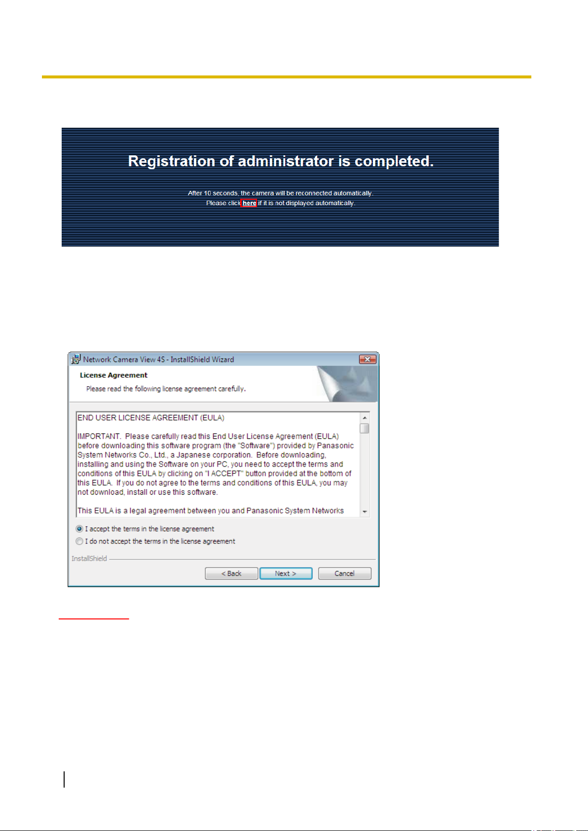
A registration completion screen is displayed after the user name and password registration for the
administrator have been completed. The camera will be automatically reconnected to about 10 seconds after
this screen is displayed. If the camera is not automatically reconnected to, click “here”.
Operating Instructions 3
Page 4
Preface
An authentication screen is displayed after reconnecting to the camera. Enter the registered user name and
password to use the camera.
Viewer software
It is necessary to install the viewer software “Network Camera View 4S” (ActiveX®) to display images on a PC.
This software can be installed directly from the camera or by selecting the [Install] button next to [Viewer
Software] on the menu of the CD-ROM provided, and then following the on-screen instructions.
IMPORTANT
• The default setting of “Automatic installation” is “On”. Follow the instructions on page 208 when the
message is displayed on the information bar of the browser.
• When the “Live” page is displayed for the first time, the install wizard of the ActiveX control required to
display images from the camera will be displayed. Follow the instructions of the wizard.
• When the install wizard is displayed again even after completing the installation of the ActiveX, restart
the PC.
• The viewer software used on each PC should be licensed individually. The number of installations of
the viewer software from the camera can be checked on the [Upgrade] tab of the “Maintenance” page
(®page 182). Refer to your dealer for the software licensing.
4 Operating Instructions
Page 5

Table of Contents
Table of Contents
1 Monitor images on a PC ..........................................................................8
1.1 Monitor images from a single camera .............................................................................8
1.2 About the “Live” page ....................................................................................................10
1.3 Monitor images from multiple cameras ........................................................................17
2 Monitor images on a cellular phone/mobile terminal .........................18
2.1 Monitor images on a cellular phone ..............................................................................18
2.2 Monitor images on a mobile terminal ............................................................................20
3 Action at an alarm occurrence ..............................................................28
3.1 Alarm type ........................................................................................................................28
3.2 Action at an alarm occurrence .......................................................................................28
4 Transmit images onto an FTP server ...................................................30
4.1 Transmit an alarm image at an alarm occurrence (Alarm image
transmission) ...................................................................................................................30
4.2 Transmit images at a designated interval or period (FTP periodic image
transmission) ...................................................................................................................30
5 About the network security ...................................................................31
5.1 Equipped security functions ..........................................................................................31
6 Display the setup menu from a PC .......................................................32
6.1 How to display the setup menu .....................................................................................32
6.2 How to operate the setup menu .....................................................................................34
6.3 About the setup menu window ......................................................................................36
7 Configure the basic settings of the camera [Basic] ...........................38
7.1 Configure the basic settings [Basic] .............................................................................38
7.1.1 Configure the washer settings (“Washer control” setup menu) ......................................43
7.2 Configure the Internet settings [Internet] .....................................................................43
8 Configure the settings relating to images and audio [Image/
Audio] ......................................................................................................46
8.1 Configure the settings relating to the image capture mode [JPEG/H.264] ................46
8.2 Configure the settings relating to JPEG images [JPEG/H.264] ..................................47
8.3 Configure the settings relating to H.264 images [JPEG/H.264] ..................................49
8.4 Configure the settings relating to the camera operations [Cam. Function] ..............55
8.5 Configure the settings relating to image position [Image/Position] ..........................58
8.5.1 Configure the settings relating to image quality (“Image adjust” setup menu) ...............59
8.5.2 Set mask areas ..............................................................................................................68
8.5.3 Configure the settings relating to the preset positions (“Preset position” setup
menu) .............................................................................................................................71
8.5.4 Configure the settings relating to the auto pan function (“Auto pan” setup menu) .........75
8.5.5 Configure the settings relating to patrol (“Patrol” setup menu) .......................................76
8.5.6 Configure the settings relating to auto track (“Auto track” setup menu) .........................78
8.5.7 Configure the settings relating to direction/angle setting (“Direction/Angle setting” setup
menu) .............................................................................................................................84
8.5.8 Configure the settings relating to the privacy zone (“Privacy zone” setup menu) ..........85
8.5.9 Configure the VIQS setting .............................................................................................88
8.5.10 Configure the VIQS area ................................................................................................91
8.6 Configure the settings relating to audio [Audio] .........................................................93
Operating Instructions 5
Page 6

Table of Contents
9 Configure the multi-screen settings [Multi-screen] ............................97
10 Configure the alarm settings [Alarm] ...................................................99
10.1 Configure the settings relating to the alarm action [Alarm] .......................................99
10.2 Configure the settings relating to the camera action on alarm occurrence
[Alarm] ............................................................................................................................101
10.2.1 Configure the settings relating to Preset per sender (“Preset per sender” setup
menu) ...........................................................................................................................103
10.2.2 Configure settings relating to image quality on alarm action ........................................104
10.2.3 Configure settings relating to alarm E-mail notifications ..............................................105
10.2.4 Configure settings relating to FTP transmissions of alarm images ..............................106
10.2.5 Configure settings relating to Panasonic alarm protocol notification when an alarm
occurs ...........................................................................................................................107
10.2.6 Configure settings relating to HTTP alarm notification when an alarm occurs .............108
10.3 Configure the settings relating to the alarm output terminal [Alarm] ......................108
10.4 Change the AUX name [Alarm] ....................................................................................109
10.5 Configure the VMD settings [VMD area] .....................................................................110
10.6 Configure the settings relating to the audio detection [Audio detection] ...............114
10.7 Configuration of the settings relating to alarm notification [Notification] ..............116
10.7.1 Configure the settings relating to Panasonic alarm protocol ........................................117
10.7.2 Configure the settings relating to HTTP alarm notification ...........................................119
11 Configure the settings relating to the authentication [User
mng.] .....................................................................................................121
11.1 Configure the settings relating to the user authentication [User auth.] ..................121
11.2 Configure the settings relating to the host authentication [Host auth.] ..................122
11.3 Configure the settings relating to the priority stream [System] ...............................123
12 Configuring the network settings [Network] .....................................126
12.1 Configure the network settings [Network] ..................................................................126
12.2 Configure advanced network settings [Advanced] ...................................................130
12.2.1 Configure the settings related to sending E-mails ........................................................131
12.2.2 Configure the settings related to FTP transmission .....................................................134
12.2.3 Configure the settings relating to the NTP server ........................................................137
12.2.4 Configure the UPnP settings ........................................................................................139
12.2.5 Configure the HTTPS settings ......................................................................................140
12.2.6 Configure the settings relating to DDNS ......................................................................142
12.2.7 Configure the settings relating to SNMP ......................................................................142
12.2.8 Configure the Diffserv settings .....................................................................................143
12.3 How to configure HTTPS settings ...............................................................................144
12.3.1 Configuration of HTTPS connections ...........................................................................145
12.3.2 Generation of the CRT key (SSL encryption key) ........................................................146
12.3.3 Generation of CSR (Certificate Signing Request) ........................................................147
12.3.4 Installation of the server certificate ...............................................................................149
12.4 Access the camera using the HTTPS protocol (for pre-installed certificate) ..........150
12.4.1 Installation of the root certificate ...................................................................................150
12.4.2 Configuration of the host file .........................................................................................155
12.5 Access the camera using the HTTPS protocol (for CA Certification) ......................161
12.5.1 Install the security certificate ........................................................................................162
12.6 How to configure the settings relating to DDNS ........................................................168
12.6.1 Configuration of the DDNS service (Example of the “Viewnetcam.com” service) ........169
12.6.2 When using the “Viewnetcam.com” service .................................................................170
12.6.3 Procedure to register information for the “Viewnetcam.com” service ...........................170
12.6.4 Checking the information registered for the “Viewnetcam.com” service ......................172
6 Operating Instructions
Page 7

Table of Contents
12.6.5 When using “Dynamic DNS Update” ............................................................................172
12.6.6 When using “Dynamic DNS Update(DHCP)” ...............................................................172
13 Configure the settings relating to the schedules [Schedule] ..........174
13.1 How to set the schedules .............................................................................................177
13.2 How to delete the set schedule ....................................................................................179
14 Extension unit setting [Extension unit] (WV-SUD6FRL1) .................181
15 Maintenance of the camera [Maintenance] ........................................182
15.1 Check the system log [System log] .............................................................................182
15.2 Upgrade the firmware [Upgrade] .................................................................................182
15.3 Check the status [Status] .............................................................................................184
15.3.1 Damage notification function ........................................................................................186
15.4 Reset the settings/Reboot the camera [Default reset] ...............................................187
15.5 Settings data/backing up or restoring logs [Data] .....................................................188
16 Using the CD-ROM ...............................................................................190
16.1 About the CD launcher .................................................................................................190
16.2 Installing Panasonic “IP Setting Software” ................................................................191
16.3 Installing the manuals ..................................................................................................192
16.4 Installing the Viewer software ......................................................................................192
16.5 Configure the network settings of the camera using the Panasonic “IP Setting
Software” .......................................................................................................................193
17 About the displayed system log .........................................................196
18 Troubleshooting ...................................................................................200
Operating Instructions 7
Page 8

1 Monitor images on a PC
1 Monitor images on a PC
The following are descriptions of how to monitor images from the camera on a PC.
1.1 Monitor images from a single camera
1. Start up the web browser.
2. Enter the IP address designated using the Panasonic “IP Setting Software” in the address box of the
browser.
• Example when entering an IPv4 address: http://URL registered using IPv4 address
http://192.168.0.10/
• Example when entering an IPv6 address: http://[URL registered using IPv6 address]
http://[2001:db8::10]/
<Example of IPv4 access>
<Example of IPv6 access>
IMPORTANT
• When the HTTP port number is changed from “80”, enter “http://IP address of the camera + : (colon)
+ port number” in the address box of the browser. (Example: http://192.168.0.11:8080)
• When the PC is in a local network, configure the proxy server setting of the web browser (under
[Internet Options...] under [Tools] of the menu bar) to bypass the proxy server for the local address.
Note
• Refer to page 161 for further information about the case in which “HTTPS” is selected for
“HTTPS” - “Connection” on the [Advanced] tab of the “Network” page (®page 126).
8 Operating Instructions
Page 9

1 Monitor images on a PC
3. Press the [Enter] key on the keyboard.
→ The “Live” page will be displayed. Refer to page 10 for further information about the “Live” page.
When “On” is selected for “User auth.”, the authentication window will be displayed before displaying live
images for the user name and password entries.
IMPORTANT
• Change this password periodically.
• When displaying multiple H.264 images on a PC, images may not be displayed depending on the
performance of the PC.
Note
• The maximum number of concurrent access user is 14 including users who is receiving H.264 images
and users who are receiving JPEG images. Depending on the set values for “Bandwidth control(bit
rate)” and “Max bit rate (per client)”, the maximum concurrent access number may be 14 or less users.
When 14 users are concurrently accessing, the access limit message will be displayed for users who
subsequently attempt to access. When “Multicast” is selected for “Transmission type” of “H.264”, only
the first user who accessed to monitor H.264 images will be included in the maximum number. The
second and subsequent users who are monitoring H.264 images will not be included in the maximum
number.
• When “On” is selected for “H.264 transmission” (®page 49), H.264 images will be displayed. When
“Off” is selected, a JPEG image will be displayed. It is possible to display a JPEG image even when
“On” is selected for “H.264 transmission”. In this case, the refresh interval of JPEG images will be
limited to 5 fps.
• The refresh interval may become longer depending on a network environment, PC performance,
photographic subject, access traffic, etc.
<Refresh interval of JPEG images>
When “On” is selected for “H.264 transmission”
max. 5 fps
When “Off” is selected for “H.264 transmission”
max. 30 fps
Operating Instructions 9
Page 10
1
②
①
③
⑤
④
⑥
⑧
⑨
⑦
⑪
⑯
⑰⑱⑲⑳
21
⑩
⑫
⑬⑭
⑮
㉒
㉓
㉔
1 Monitor images on a PC
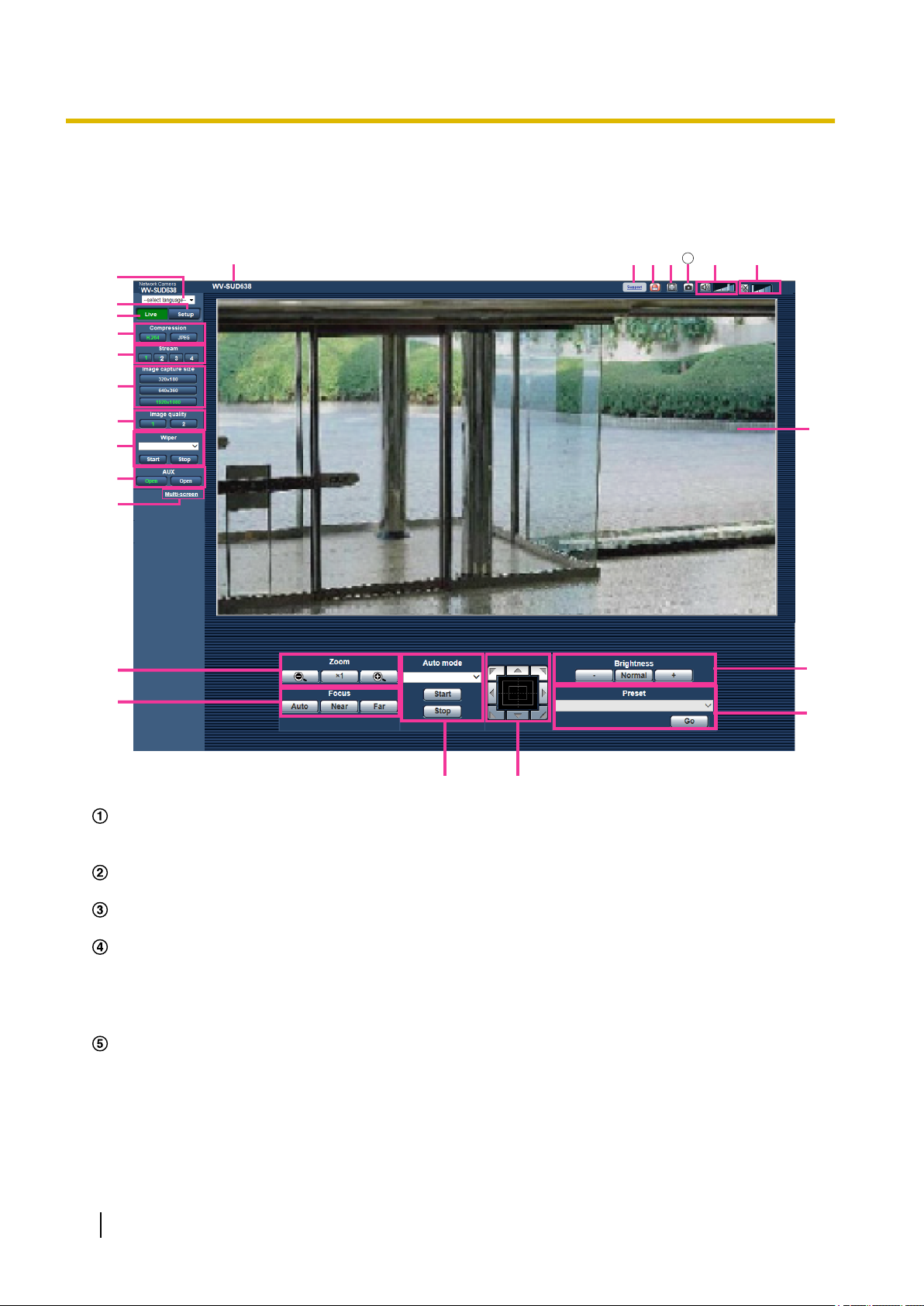
1.2 About the “Live” page
[select language] pull-down-menu
The camera’s display language can be selected. The default language can be set in the [Language] in the
[Basic] settings. (®page 38)
[Setup] button
Displays the setup menu. The button will turn green and the setup menu will be displayed.
[Live] button
Display the “Live” page. The button will turn green and the “Live” page will be displayed.
[Compression] buttons
• [H.264] button: The letters “H.264” on the button will turn green and an H.264 image will be displayed.
When “On” is selected for “H.264 transmission” of “H.264(1)”, “H.264(2)”, “H.264(3)”, “H.264(4)”, the
[H.264] button will be displayed. (®page 49)
• [JPEG] button: The letters “JPEG” on the button will turn green and JPEG image will be displayed.
[Stream] buttons
These buttons will be displayed only when an H.264 image is displayed.
• [1] button: The letter “1” will turn green and images in the main area will be displayed in accordance
with the setting of “H.264(1)”. (®page 49)
• [2] button: The letter “2” will turn green and images in the main area will be displayed in accordance
with the setting of “H.264(2)”. (®page 49)
10 Operating Instructions
*1
Page 11

1 Monitor images on a PC
• [3] button: The letter “3” will turn green and images in the main area will be displayed in accordance
with the setting of “H.264(3)”. (®page 49)
• [4] button: The letter “4” will turn green and images in the main area will be displayed in accordance
with the setting of “H.264(4)”. (®page 49)
[Image capture size] buttons
These buttons will be displayed only when a JPEG image is displayed.
Aspect ratio of
“4:3”
Aspect ratio of
“16:9”
[1280x960] The letters “1280x960” will turn green and images in the
main area will be displayed in 1280 x 960 (pixels).
[800x600] The letters “800x600” will turn green and images in the
main area will be displayed in 800 x 600 (pixels).
[VGA] The letters “VGA” will turn green and images in the main
area will be displayed in VGA size.
[400x300] The letters “400x300” will turn green and images in the
main area will be displayed in 400 x 300 (pixels).
[QVGA] The letters “QVGA” will turn green and images in the main
area will be displayed in QVGA size.
[160x120] The letters “160x120” will turn green and images in the
main area will be displayed in 160 x 120 (pixels).
[1920x1080] The letters “1920x1080” will turn green and images in the
main area will be displayed in 1920x1080 (pixels).
[1280x720] The letters “1280x720” will turn green and images in the
main area will be displayed in 1280 x 720 (pixels).
[640x360] The letters “640x360” will turn green and images in the
main area will be displayed in 640 x 360 (pixels).
[320x180] The letters “320x180” will turn green and images in the
main area will be displayed in 320 x 180 (pixels).
[160x90] The letters “160x90” will turn green and images in the
main area will be displayed in 160 x 90 (pixels).
Note
• Images are displayed in the image capture size selected in “JPEG(1)”, “JPEG(2)”, or “JPEG(3)” of
[JPEG] on the [JPEG/H.264] tab.
• When “1920x1080”, “1280x960”, or “1280x720” is selected for the image capture size, it may
become smaller than the actual size depending on the window size of the web browser.
[Image quality] buttons
These buttons will be displayed only when a JPEG image is displayed.
• [1] button: Images in the main area will be displayed in accordance with the setting for “Quality1” of
“Image quality setting”. (®page 47)
• [2] button: Images in the main area will be displayed in accordance with the setting for “Quality2” of
“Image quality setting”. (®page 47)
[Wiper]
Select an operation from the pull-down menu and click the [Start] button. The selected operation will start.
Click the [Stop] button to stop the operation.
*2
• Continuous:High: The wiper wipes the front glass once every 4 seconds.
• Continuous:Low: The wiper wipes the front glass once every 8 seconds.
• 1shot: The wiper wipes the front glass 5 times.
• Washer: Performs the following washer/wiper operations.
1. The camera moves to the washer position.
Operating Instructions 11
Page 12
1 Monitor images on a PC
2. The washer operates according to the “Pulse width” setting. (®page 43)
3. While wiping according to the “Wiper count” setting (®page 43), the camera moves back to its original
position.
Note
• During washer operations, wiper [Start] and [Stop], pan/tilt/zoom/focus control, Auto mode [Start],
and preset action [Start] cannot be operated.
• “Washer” can only be selected when “Washer control” is selected for “Relay output” on the
[Basic] tab of the “Basic” page. Refer to page 43 for information on washer settings.
• When “Continuous:High” or “Continuous:Low” is selected and the [Start] button is clicked, the wiper
will stop after a maximum of 5 minutes from when the [Start] button was clicked.
• During pan/tilt/zoom controls, [Start] may not be able to be operated for the washer.
• If the wiper or washer operations are started during auto tracking operations, the wiper may be
detected and tracked.
[AUX] button
These buttons will be displayed only when “Terminal 3” of “Alarm” is set to “AUX output” on the setup menu.
(®page 99)
• [Open] button: The characters “Open” on the button will turn green and the status of the AUX connector
will be open.
• [Close] button: The characters “Close” on the button will turn green and the status of the AUX
connector will be closed.
Note
• The names of “AUX”, “Open” and “Close” can be changed. (®page 109)
[Multi-screen]
Images from multiple cameras can be displayed on a multi-screen by registering cameras on the setup
menu. (®page 17)
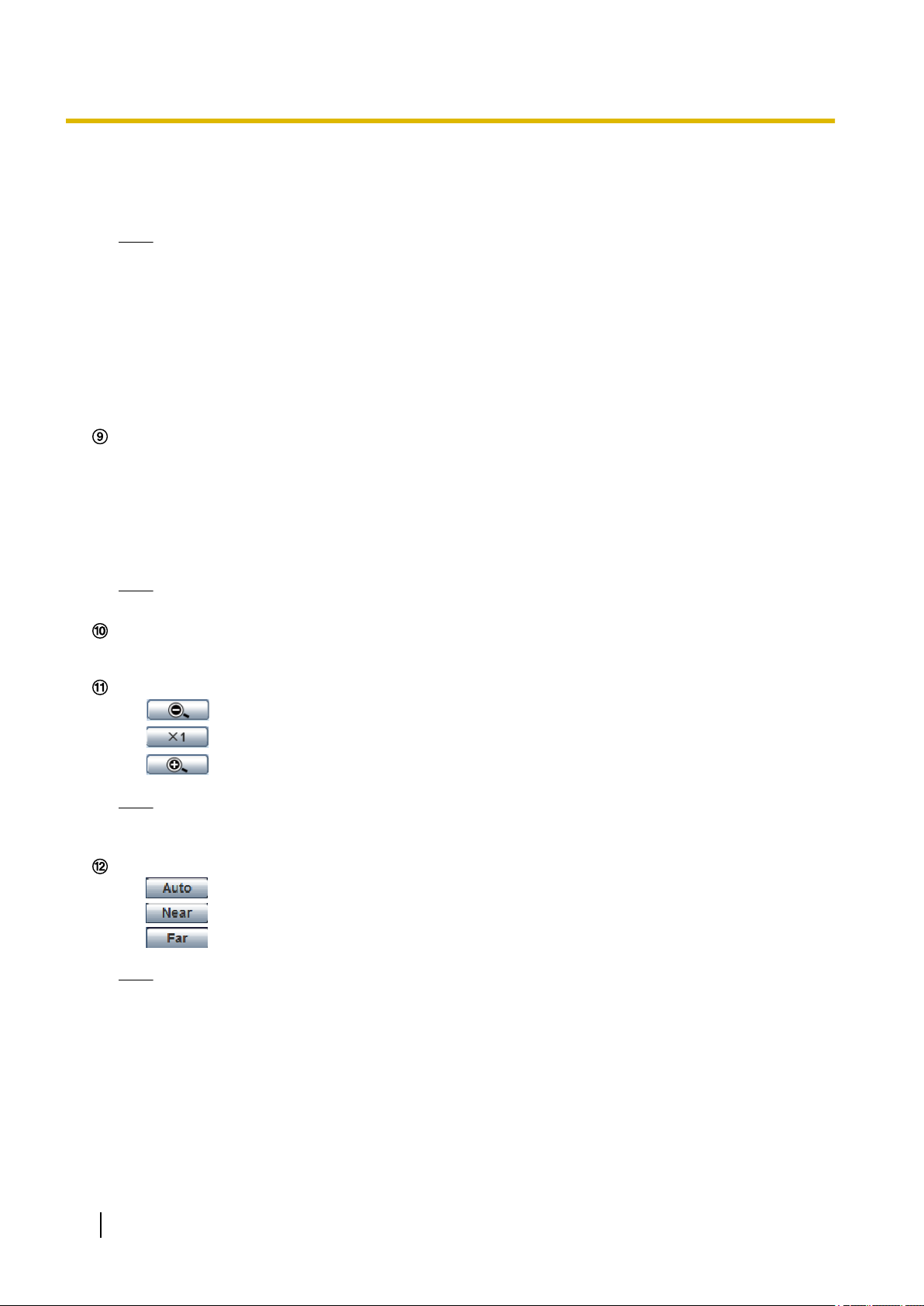
[Zoom] button
•
*2
: Click this button to adjust the zoom ratio to the “Wide” side.
• : Click this button to set the zoom ratio to x1.0.
• : Click this button to adjust the zoom ratio to the “Tele” side.
Note
• The [Zoom] button cannot be operated while the washer is operating. Operate the control pad/
buttons after the washer has finished operating.
[Focus] button
•
*2
: Click this button to adjust the focus automatically.
• : Click this button to adjust the focus to the “Near” side.
• : Click this button to adjust the focus to the “Far” side.
Note
• The [Focus] button cannot be operated while the washer is operating. Operate the control pad/
buttons after the washer has finished operating.
• When shooting the following place or the following subjects, focus may not be adjusted
automatically. Adjust the focus manually.
– Shiny or strongly reflective subject
– Subject through the glass with dew or smudge
– Two subjects whose distances from the camera are different
– Less contrast subject (e.g. white wall)
– Horizontal-striped subject such as a window blind
12 Operating Instructions
Page 13

1 Monitor images on a PC
– Inclined subject
– Dark subjects
Auto mode
Select an operation from the pull-down menu and click the [Start] button. The selected operation will start.
Click the [Stop] button to stop the operation. The selected operation will stop when the camera (panning/
tilting/zooming/focusing) is operated or when an action that is to be taken according to the settings for “Self
return”(®page 55) or for “Camera action on alarm” (®page 101) starts.
Note
*2
• The [Start] button for “Auto mode” cannot be operated while the washer is operating. Operate auto
mode after the washer has finished operating.
• Auto track: Automatically tracks objects in the shooting area.
Note
• With the Auto track feature, objects moving in the screen are picked out and automatically tracked.
• In the following situations, targets may not be able to be tracked, or false detections may occur.
– when there is little contrast between the subject and the background
– when the front glass is dirty or wet
– when there are large changes to the lighting intensity
– when there are many moving objects other than the subject
– when there is a change to the axis of the camera’s lens
– when the subject moves directly underneath the camera
– when there is harsh flickering
– when there are reflections from light entering the front glass due to reflections from a window
or road, or from a backlight
– when the target is hidden behind a utility pole or other objects
– when the subject passes by other moving objects
– when the target moves too fast or too slow
– when the camera is shaking
• When the zoom ratio is set to the “Tele” side, it may be difficult to obtain accuracy with the auto
tracking function. It is recommended to use the auto tracking function with setting the zoom ratio
to the “Wide” side.
• During auto tracking, if the camera is operated using the control pad or by other methods, or if an
alarm occurs, auto tracking is stopped.
• Auto pan: Automatically pans between the start position and the end position set in advance
(®page 75).
Even when the camera is operated for zooming or focusing, the camera continues panning. (However,
panning will stop when the zoom button (x1) is clicked.)
• Preset sequence: Automatically moves to the preset positions (®page 71) orderly (start from the
lowest preset position number).
• 360 map-shot: Moves 45° horizontally at a time and repeats 8 times to shoot images of each 45°
position (45° x 8 = 360°), and then displays 8 thumbnail images of each 45° position (45° x 8 = 360°)
on a newly opened window. When a thumbnail image is clicked, the camera moves to the respective
position and live images will be displayed on the “Live” page.
• Preset map-shot: 8 thumbnail images of the preset position 1-8 (®page 71) will be displayed orderly
on a newly displayed window. When a thumbnail image is clicked, the camera moves to the respective
position and live images will be displayed on the “Live” page.
Note
• Do not operate the browser until all the thumbnail images are displayed and the camera returns to
the original position (where the camera was when “360 map-shot” or “Preset map-shot” was carried
out).
Operating Instructions 13
Page 14

1 Monitor images on a PC
• When “360 map-shot” is carried out while the camera is moving (panning/tilting), images captured
while panning/tilting may be displayed as the thumbnail display. In this case, stop the current
operation and carry out “360 map-shot” again.
• When “Preset map-shot” is carried out with an unregistered preset position (among preset position
1-8), the thumbnail image of the preset position before the unregistered preset position will be
displayed.
In this case, the camera will not move when the thumbnail image is clicked.
• The camera will not always return to the exactly same position where it was before “360
map-shot” or “Preset map-shot” was carried out. (It may sometimes be slightly different.)
• The window on which the thumbnail images are displayed will close when clicking the following
buttons that can switch the camera channel or reload images: [Live], [Multi-screen], [H.264],
[JPEG], [Stream], [Image capture size], [Image quality], [Setup].
To display the thumbnail images again, carry out “360 map-shot” or “Preset map-shot” again.
• Patrol 1-4: Performs patrols 1-4 that were set in advance. (®page 76)
Control pad/buttons
Left-click on the control pad or buttons to adjust the horizontal/vertical position of the camera (panning/
tilting). Panning/tilting speed will be faster if a clicked point gets farther from the center point of the control
pad.
It is also possible to pan/tilt the camera by dragging the mouse.
Zoom and focus can be adjusted by right-clicking. When an upper/lower area of the control pad is
right-clicked, the displayed image will be zoomed in/out on. When a left/right area is right-clicked, the focus
will be adjusted to the Near/Far side.
Zoom can also be adjusted using the mouse wheel.
*2
Note
• The control pad/buttons cannot be operated while the washer is operating. Operate the control
pad/buttons after the washer has finished operating.
[Brightness] buttons
*2
Available range: 0 - 255
• : Images become darker.
•
: The adjusted brightness will return to the default brightness (64).
• : Images become brighter.
[Preset]
Select a preset position from the pull-down menu and click the [Go] button. The camera will move to the
selected preset position (®page 71). “H” next to the preset position number indicates the home position.
When “Home position” is selected, the camera will move to the home position. (®page 55)
When “Preset ID” is registered for a preset position, the registered preset ID will be displayed next to the
preset position number.
Note
*2
• The [Go] cannot be operated while the washer is operating. Operate auto mode after the washer
has finished operating.
Camera title
The camera title entered for “Camera title” on the [Basic] tab will be displayed. (®page 38)
[Support] button
When this button is clicked, the support site below will be displayed in a newly opened window. This website
contains technical information, FAQ, and other information.
http://security.panasonic.com/support/
Alarm occurrence indication button
This button will be displayed and will blink when an alarm has occurred. When this button is clicked, this
button will disappear. (®page 28)
*2
14 Operating Instructions
Page 15

1 Monitor images on a PC
Note
• Since the blinking of the alarm occurrence indication button is not coupled to forwarding E-mails,
or other operations, check the settings of each operation separately.
Full screen button
Images will be displayed on a full screen. If the full screen button is clicked once when the image displayed
in the main area is smaller than the main area, the image is displayed corresponding to its image capture
size. If the full screen button is clicked once when images are displayed corresponding to their image
capture sizes, images are displayed in full screen. To return to the “Live” page when displaying an image
in full screen, press the [Esc] key.
The aspect ratio of displayed images will be adjusted in accordance with the monitor.
Snap shot button
Click this button to take a picture (a still picture). The picture will be displayed on a newly opened window.
When right-clicking on the displayed image, the pop-up menu will be displayed. It is possible to save the
image on the PC by selecting “Save” from the displayed pop-up menu.
When “Print” is selected, printer output is enabled.
Note
• For the case of using Windows 8 or Windows 7, the following settings may be required.
Open Internet Explorer, click [Tools] ® [Internet Options] ® [Security] ® [Trusted Sites] ®
[Sites]. Register the camera address on [Website] of the displayed trusted windows. After
registration, close the web browser, and then access the camera again.
• When it takes longer than the specified period to obtain the snap shot picture due to the network
environment, the snap shot picture may not be displayed.
Mic input button
Turns on/off the audio reception (hear audio from the camera on a PC). This button will be displayed only
when “Mic input”, “Interactive(Full-duplex)” or “Interactive(Half-duplex)” is selected for “Audio transmission/
reception” on the setup menu. (®page 93)
When the audio reception is turned off, the button will turn into the button and audio from the camera
will not be heard.
Audio volume can be adjusted (Low/ Middle/ High) by moving the volume cursor
*3
.
Note
• The volume cursor is not displayed when “Audio detection” is used.
• When the camera is restarted, the adjusted volume level (for the reception) will return to the level
that had been set on the [Audio] tab on the setup menu. (®page 93)
• Actual volume level will change in three steps even though the volume cursor can be adjusted
minutely.
Audio output button
*3
Turns on/off the audio transmission (play audio from the PC on the unit speaker). This button will be
displayed only when “Audio output”, “Interactive(Full-duplex)” or “Interactive(Half-duplex)” is selected for
“Audio mode” on the setup menu. (®page 93)
The button will blink during the audio transmission.
When the audio transmission is turned off, the button will turn into the
button and audio from the PC
will not be heard.
Audio output volume can be adjusted (Low/Middle/High) by moving the volume cursor .
Note
• When a user is using the audio transmission function with “Interactive(Half-duplex)” selected, the
receiver button and the transmission button will be inoperable for the other users. When
“Interactive(Full-duplex)” is selected, the transmission button is inoperable for other users.
Operating Instructions 15
Page 16

1 Monitor images on a PC
• The duration of continuous audio transmission can be configured in the [Audio] tab of the setup
menu. Audio output stops when the specified time has passed. To turn the audio transmission
function on, click the [Audio output] button again.
• When the camera is restarted, the adjusted volume level (for both the audio transmission and
reception) will return to the level that had been set on the [Audio] tab on the setup menu.
(®page 93)
• Actual volume level will change in three steps even though the volume cursor can be adjusted
minutely.
Main area
Images from the camera will be displayed in this area.
The current time and date will be displayed according to the settings configured for “Time display format”
and “Date/time display format”. (®page 39)
In addition, when being adjusted, the status of brightness (®page 40), camera position (®page 56),
and the preset ID (®page 73) will be displayed as well as the characters configured for “Camera title on
screen” (®page 40). The number of lines for the display is 3. Click a desired point in the main area on
the “Live” page that is to be the center of the angle of view. The camera moves to adjust the position in
order to set the clicked point as the center.*4 When selecting an area in the main area by dragging the
mouse, the selected area will be located at the center of the main area. In this case, the zoom ratio will be
adjusted automatically.
A zoom operation can be performed using the mouse wheel.
When the main area of the “Live” page is right-clicked, “Auto track” starts for the clicked object. Depending
on the targeted object or its surroundings, “Auto track” may not perform normally.
*4
Note
• When the camera is operated by a user with a low access level, images displayed on the screen
may be changed temporarily. This does not affect operation of the camera.
• Depending on the PC in use, screen tearing* may occur due to the GDI restrictions of the OS when
the shooting scene drastically changes or when the wiper is in use.
*A phenomenon in which portions of the screen are displayed out of alignment.
*1
Only operable by users whose access level is “1. Administrator”.
*2
Only operable by users whose access level is “1. Administrator” or “2. Camera control” when “On” is selected for “User
auth.” (®page 121)
*3
Operable by users who belong to the access level selected for “Permission level of audio trans./recep.” on the [Audio] tab of the
“Image/Audio” page. Refer to page 93 for the permission level of audio.
*4
As the tilt angle approaches 90°, because the difference between the specified position and the actual direction the camera is moving
increases, the camera may not move to the specified angle of view.
16 Operating Instructions
Page 17
②
①
③
1 Monitor images on a PC
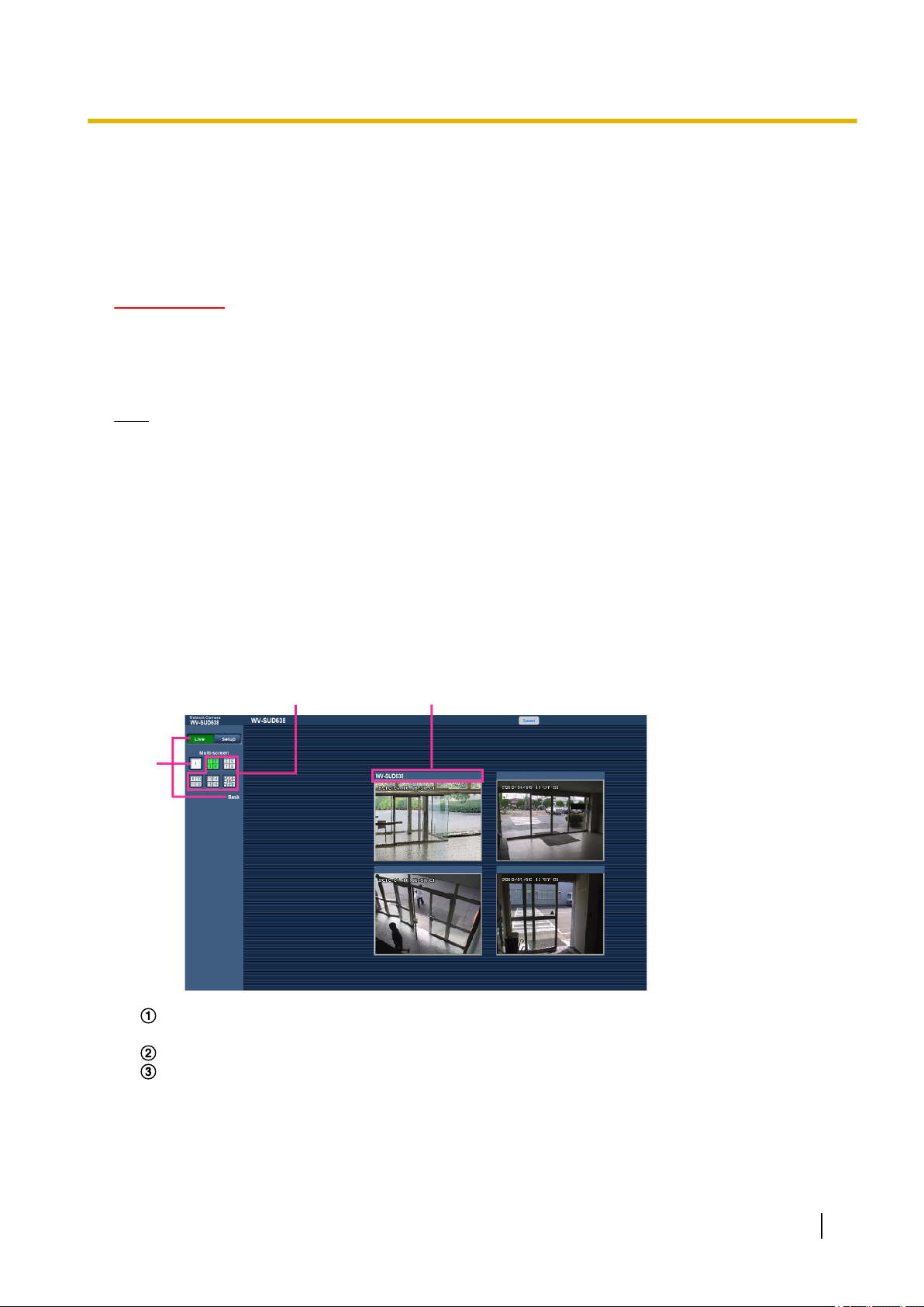
1.3 Monitor images from multiple cameras
Images from multiple cameras can be displayed on a multi-screen. Images from 4 cameras (up to 16 cameras)
can be displayed simultaneously. To display images on a multi-screen, it is necessary to register cameras in
advance. 4 cameras can be registered as a group and up to 4 groups (16 cameras) can be registered.
(®page 97)
IMPORTANT
• When displaying images on a 16-screen, panning, tilting and zooming operations become unavailable
for images from cameras with Pan/Tilt/Zoom functions.
• When the power is turned off or the LAN cable is disconnected while displaying images, displaying
images on a multi-screen from the “Live” page will become unavailable.
Note
• When displaying images on a 4-screen, panning, tilting and zooming operations become available only
for images from cameras with Pan/Tilt/Zoom functions. Refer to our website
(http://security.panasonic.com/support/info/) for further information about the compatible cameras and
their versions.
• Only JPEG images can be displayed on a multi-screen. Audio will not be heard.
• When displaying the image on a multi-screen and “16:9” is selected for the aspect ratio, the image will
be displayed altered vertically to the aspect ratio of “4:3”.
• “Network Camera Recorder with Viewer Software Lite” which supports live monitoring and recording
images from multiple cameras is available. For further information, refer to our website
(http://security.panasonic.com/support/info/).
1. Click the desired [Multi-screen] on the “Live” page.
→ Images from the registered cameras will be displayed on a selected multi-screen (screen can be split
up to 16 areas). The following are instructions when displaying on a 4-split screen.
To show 1 camera screen, click the [Live] button.
You can also click “1” below “Multi-screen” or “Back” to display the camera's “Live” page.
Click the [Multi-screen] button to display images from cameras in a multi-screen of 4 to 16 screens.
Click a camera title. Live images from the camera corresponding to the clicked camera title will be
displayed on the “Live” page of the newly opened window.
Operating Instructions 17
Page 18

2 Monitor images on a cellular phone/mobile terminal
2 Monitor images on a cellular phone/mobile
terminal
2.1 Monitor images on a cellular phone
It is possible to connect to the camera using a cellular phone via the Internet and monitor images (JPEG only)
from the camera on the screen of the cellular phone. It is also possible to refresh images to display the latest
image.
IMPORTANT
• When the authentication window is displayed, enter the user name and password.
To enhance the security, change the password periodically. (®page 121)
• If the cellular phone in use is not compatible with UTF-8 encode, it is impossible to display the screen
correctly.
• When “VGA”, “QVGA”, “640x360”, or “320x180” is not selected one time or more for either one of
“JPEG(1)”, “JPEG(2)”, or “JPEG(3)” of [JPEG] on the [JPEG/H.264] tab, images cannot be viewed from
cellular phones.
Note
• It is necessary to configure the network settings of the cellular phone in advance to connect to the
Internet and monitor images from the camera. (®page 126)
• When “Auto” is selected for “Language”, the screen is displayed in English. If you want the screen to
be displayed in Japanese or Chinese, select “Japanese” or “Chinese” for “Language”. (®page 38)
18 Operating Instructions
Page 19
A
B
C
D
E
F
G
H
2 Monitor images on a cellular phone/mobile terminal
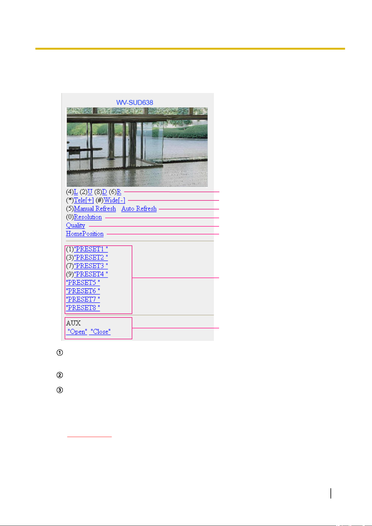
1. Access to “http://IP address/mobile”
*1
cellular phone.
→ Images from the camera will be displayed.
or “http://Host name registered in the DDNS server/mobile” using a
Pan/Tilt
*2
Controls the camera direction. The camera will pan or tilt to each direction by pressing the
corresponding dial key.
Zoom display
*2
It is possible to perform zooming operations of the camera by pressing “*” or “#”.
Refresh control
Press the dial key “5” or the [Manual Refresh] button to refresh the camera images.
Press the [Auto Refresh] button to refresh the images from the camera in 5-second intervals.
When the dial key “5” or the [Manual Refresh] button is pressed again, the refresh mode of the camera
will return to manual refresh.
IMPORTANT
• Transmission will be periodically performed when “Auto Refresh” is selected for the camera
image. Confirm the contract plan of the cellular phone in use before using this function.
• Depending on the cellular phone in use, “Auto Refresh” may be unavailable.
Operating Instructions 19
Page 20

2 Monitor images on a cellular phone/mobile terminal
Resolution control
Changes the image capture size by pressing the dial key “0”.
• Image in the aspect ratio of “4:3”: Changes the image capture size between 320x240 (default) and
640x480.
• Image in the aspect ratio of “16:9”: Changes the image capture size between 320x180 (default)
and 640x360.
Image quality control
It is possible to change the image quality between “Quality1” and “Quality2”. (®page 47)
Home position
*2
The camera will move to the home position. (®page 55)
Home position will be displayed only when home position is set.
*2
Preset
The camera will move to the designated preset position to display images by pressing the dial key
corresponding to the desired channel. (The dial key numbers are not displayed for Preset No. 5 or
greater. Only preset IDs will be displayed for them.) (®page 71)
AUX control
*2
Controls the AUX terminal.
This function is only displayed when “AUX output” is set to “Terminal 3” on the settings menu. (Refer
to page 99)
Note
• Some cellular phones cannot change the image capture size even when resolution is changed by
resolution control.
• Depending on the image capture size selected for “JPEG(1)”, “JPEG(2)”, or “JPEG(3)”, “Resolution”
may not be able to be used.
• When the HTTP port number is changed from “80”, enter “http://IP address: (colon) + port number/
mobile”*1 in the address box of the browser. When using the DDNS function, access to “http://Host
name registered in the DDNS server: (colon) + port number/mobile”.
• When “HTTPS” is selected for “HTTPS” - “Connection” on the [Advanced] tab of the “Network” page,
enter as follows.
“https://IP address: (colon) + port number/mobile” or “https://Host name registered in the DDNS server:
(colon) + port number/mobile”
• When the authentication window is displayed, enter the user name of an administrator or user and
password. Depending on the cellular phone in use, password entry may be required each time the
screen is switched.
• It is impossible to receive audio using a cellular phone.
• Depending on the cellular phone in use, larger size images may not be displayed. In this case, selecting
“9 Low” for “Image quality setting” of “JPEG” (®page 47) may sometimes solve this problem.
• Depending on the cellular phone in use or its contract plan, it may be impossible to access.
*1
IP address is the global WAN IP address of the router that can be accessed via the Internet.
*2
When “User auth.” is set to “On” (®page 121), only users with the access level of “1. Administrator” or “2. Camera control” will be
displayed.
2.2 Monitor images on a mobile terminal
It is possible to connect to the camera using a mobile terminal via the Internet and monitor images (MJPEG
or JPEG) from the camera on the screen of the mobile terminal. It is also possible to refresh images to display
the latest image.
The compatible mobile terminals are shown as follows. (As of August, 2016)
– iPad, iPhone, iPod touch (iOS 4.2.1 or later)
– Android™ mobile terminals
20 Operating Instructions
Page 21

A
B
C
D
2 Monitor images on a cellular phone/mobile terminal
When an Android terminal is used, an MJPEG format image is displayed by the Firefox® browser, but a JPEG
format image is displayed by the standard browser.
For further information about compatible devices, refer to our website
(http://security.panasonic.com/support/info/).
IMPORTANT
• When the authentication window is displayed, enter the user name and password.
To enhance the security, change the password periodically. (®page 121)
Note
• It is necessary to configure the network settings of the mobile terminal in advance to connect to the
Internet and monitor images from the camera. (®page 126)
1. Access to “http://IP address/cam”
mobile terminal.
→ Images from the camera will be displayed.
*1
or “http://Host name registered in the DDNS server/cam”*2 using a
Live images area
Displays images from the camera.
Operation buttons area
When functions are selected in the function selection area D, buttons to operate those functions are
displayed.
Zoom operation area
Buttons to operate the zoom are displayed.
Function selection area
Displays the functions that can be operated. When a function is selected from here it is displayed in
the operation buttons area B.
Operating Instructions 21
Page 22

C D
A
B E
F
2 Monitor images on a cellular phone/mobile terminal
2. Click the button of the function that you want to operate.
Pan/Tilt
Preset
Resolution control
AUX control
Focus display
Zoom display
Each function is explained below.
22 Operating Instructions
Page 23

2 Monitor images on a cellular phone/mobile terminal
Pan/Tilt
Press the button to display the buttons used to operate pan/tilt on the screen. The pan/tilt can be
adjusted in each direction with the , , , and buttons.
Preset
Press the
button to display the buttons used to select the preset position on the screen. Camera
images are displayed of the registered preset camera directions according to the preset numbers
selected from the buttons.
• Only position numbers 1-4 for the preset positions are displayed.
• Only registered preset positions are displayed. Unregistered preset positions are not displayed.
Operating Instructions 23
Page 24

2 Monitor images on a cellular phone/mobile terminal
Resolution control
Press the button to display the buttons used to select the resolution on the screen. The resolution
can be changed by selecting a resolution setting from the buttons.
Images are displayed in the image capture size selected in “JPEG(1)”, “JPEG(2)”, or “JPEG(3)” of
[JPEG] on the [JPEG/H.264] tab.
24 Operating Instructions
Page 25

2 Monitor images on a cellular phone/mobile terminal
AUX control
Press the button to display the buttons used to operate the AUX output on the screen. The AUX
output terminals can be controlled with the and buttons.
This function is only displayed when “Terminal 3” is set to “AUX output” on the settings menu.
(®page 99)
Operating Instructions 25
Page 26

2 Monitor images on a cellular phone/mobile terminal
Focus display
Press the button to display the buttons used to operate the focus on the screen. The camera’s
focus can be operated with the , , and buttons.
Zoom display
The camera’s zoom can be operated with the
, , and buttons.
26 Operating Instructions
Page 27

2 Monitor images on a cellular phone/mobile terminal
Note
• You can change the image size displayed on the mobile terminal by accessing the following addresses.
– Large display: http://IP address/cam/dl
– Medium display: http://IP address/cam/dm
– Small display: http://IP address/cam/ds
• When the resolution is changed by the resolution control, the displayed resolution changes but the
image size remains the same.
• When the HTTP port number is changed from “80”, enter “http://IP address: (colon) + port number/
cam”*1 in the address box of the browser. When using the DDNS function, access to “http://Host name
registered in the DDNS server: (colon) + port number/cam”*2.
• When “HTTPS” is selected for “HTTPS” - “Connection” on the [Network] tab of the “Network” page,
enter as follows.
“https://IP address: (colon) + port number/cam” or “https://Host name registered in the DDNS server:
(colon) + port number/cam”
• When the authentication window is displayed, enter the user name of an administrator or user and
password. Depending on the mobile terminal in use, password entry may be required each time the
screen is switched.
• It is impossible to transmit/receive audio using a mobile terminal.
• Depending on the mobile terminal in use, larger size images may not be displayed. In this case,
selecting “9 Low” for “Image quality setting” of “JPEG” (®page 47) may sometimes solve this
problem.
• Depending on the mobile terminal in use or its contract plan, it may be impossible to access.
*1
IP address is the global WAN IP address of the router that can be accessed via the Internet. However, when accessing the same
LAN as the camera with a wireless compatible mobile terminal, the IP address is the local IP address.
*2
Only when accessing the camera via the Internet.
Operating Instructions 27
Page 28

3 Action at an alarm occurrence
3 Action at an alarm occurrence
The alarm action (camera action at an alarm occurrence) will be performed when the following alarms occur.
3.1 Alarm type
• Terminal alarm: When connecting an alarm device such as a sensor to the alarm input terminal of the
camera, the alarm action will be performed when the connected alarm device is activated.
• VMD alarm: When motion is detected in the set VMD area, the alarm action will be performed.
*VMD stands for “Video Motion Detection”.
• Command alarm: When a Panasonic alarm protocol is received from the connected device via a network,
the alarm action will be performed.
• Auto track alarm: According to the conditions set in advance, the alarm action will be performed in the
auto tracking operations.
• Audio detection alarm: When the configured audio detection level is exceeded, the alarm action will be
performed.
3.2 Action at an alarm occurrence
Display the alarm occurrence indication button on the “Live” page
The alarm occurrence indication button will be displayed on the “Live” page at an alarm occurrence.
(®page 10)
IMPORTANT
• When “Polling(30s)” is selected for “Alarm status update mode” (®page 38), the Alarm occurrence
indication button will be refreshed in 30-second intervals. For this reason, it may take a maximum of
30 seconds until the alarm occurrence indication button is displayed on the “Live” page at an alarm
occurrence.
Notify of alarm occurrences to the device connected to the alarm connector
It is possible to output signals from the alarm output terminal of the camera and sound the buzzer when an
alarm occurs. The settings for the alarm output can be configured in the “Alarm output terminal setup” section
of the [Alarm] tab of the “Alarm” page. (®page 108)
Transmit an image onto a server automatically
An alarm image can be transmitted at an alarm occurrence to the server designated in advance. The settings
required to transmit an alarm image to a server can be configured in the [Alarm] tab of the “Alarm” page
(®page 101) and the [Advanced] tab of the “Network” page. (®page 134)
Notify of alarm occurrences by E-mail
Alarm E-mail (alarm occurrence notification) can be sent at an alarm occurrence to the E-mail addresses
registered in advance. Up to 4 addresses can be registered as recipients of the alarm E-mail. An alarm image
(still picture) can be sent with the alarm E-mail as an attached file. The settings for alarm E-mail can be
configured in the [Alarm] tab of the “Alarm” page (®page 101) and the [Advanced] tab of the “Network” page.
(®page 131)
28 Operating Instructions
Page 29

3 Action at an alarm occurrence
Notify of alarm occurrences to the designated addresses (Panasonic alarm
protocol notification)
This function is available only when a Panasonic device, such as the network disk recorder, is connected to
the system. When “On” is selected for “Panasonic alarm protocol notification”, the connected Panasonic device
will be notified that the camera is in the alarm state. The settings for Panasonic alarm protocol can be configured
in the Panasonic alarm protocol section of the [Notification] tab of the “Alarm” page. (®page 117)
Notify of alarm occurrences to the designated HTTP server (HTTP alarm
notification)
Alarm occurrence notifications can be sent at an alarm occurrence to the HTTP servers registered in advance.
Up to 5 HTTP servers can be registered as recipients of alarm notifications. The URL sent to HTTP servers
with alarm notifications can be specified. The settings for HTTP alarm notification can be configured on the
[Notification] tab of the “Alarm” page. (®page 119)
Operating Instructions 29
Page 30

4 Transmit images onto an FTP server
4 Transmit images onto an FTP server
Images can be transmitted to an FTP server. By configuring the following settings, transmission of images
captured at an alarm occurrence or captured at a designated interval to an FTP server will become available.
IMPORTANT
• When using this function, set the user name and the password to access the FTP server to restrict
users who can log into the FTP server.
4.1 Transmit an alarm image at an alarm occurrence (Alarm image transmission)
An alarm image can be transmitted at an alarm occurrence to the FTP server. To transmit alarm images to an
FTP server, it is necessary to configure the settings in advance.
FTP server settings and settings relating to alarm image transmission can be configured in the “FTP” section
of the [Advanced] tab of the “Network” page. (®page 134) Settings can also be configured from the “Alarm
image FTP transmission” settings of “Camera action on alarm” on the [Alarm] tab of the “Alarm” page.
(®page 101)
Note
• Depending on the network traffic, the number of the transmitted images may not reach the set number
of images to be transmitted.
• When “On” is selected for both the alarm image transmission function and the FTP periodic image
transmission function, the alarm image transmission function will be given priority over the FTP periodic
image transmission function. Also, when “On” is selected for the “FTP transmission retry” FTP setting
(®page 135), alarm images will be retransmitted if there is an FTP transmission failure. Therefore, if
there is continuous retransmission due to network problems or other factors, periodic transmission will
not be performed.
4.2 Transmit images at a designated interval or period (FTP periodic image transmission)
Images can be transmitted at a designated interval or period. To transmit images at a designated interval or
period, it is necessary to configure the settings in advance.
FTP server settings and settings relating to FTP periodic transmission image transmission can be configured
in the “FTP” section of the [Advanced] tab of the “Network” page. (®page 134)
Configure the schedule settings of the FTP periodic image transmission on the “Schedule” page.
(®page 177)
Note
• Depending on the line speed or the traffic, images may not be transmitted at the designated interval.
• When “On” is selected for both the alarm image transmission function and the FTP periodic image
transmission function, the alarm image transmission function will be given priority over the FTP periodic
image transmission function. Therefore, images may not be transmitted at the interval designated on
the “FTP periodic image transmission” setting.
30 Operating Instructions
Page 31

5 About the network security
5.1 Equipped security functions
The following security functions are featured in this camera.
Access restrictions by the host authentication and the user authentication
It is possible to restrict users from accessing the camera by setting the host authentication and/or the user
authentication to “On”. (®page 121, page 122)
Access restrictions by changing the HTTP port
It is possible to prevent illegal access such as port scanning, etc. by changing the HTTP port number.
(®page 128)
Access encryption by the HTTPS function
It is possible to enhance the network security by encrypting the access to cameras using the HTTPS
function. (®page 144)
IMPORTANT
• Design and enhance security countermeasures to prevent leakage of information such as image data,
authentication information (user name and password), alarm E-mail information, FTP server
information, DDNS server information, etc. Perform the countermeasure such as access restriction
(using the user authentication) or access encryption (using the HTTPS function).
• After the camera is accessed by the administrator, make sure to close the browser for added security.
• Change the administrator password periodically for added security.
5 About the network security
Note
• When user authentication (authentication error) has failed to pass 8 times within 30 seconds using the
same IP address (PC), access to the camera will be denied for a while.
Operating Instructions 31
Page 32

6 Display the setup menu from a PC
6 Display the setup menu from a PC
The settings of the camera can be configured on the setup menu.
IMPORTANT
• The setup menu is only operable by users whose access level is “1. Administrator”. Refer to
page 121 for how to configure the access level.
6.1 How to display the setup menu
1. Display the “Live” page. (®page 8)
2. Click the [Setup] button on the “Live” page.
→ The window with the user name and password entry fields will be displayed.
32 Operating Instructions
Page 33

6 Display the setup menu from a PC
3. Click the [OK] button after entering the user name and the password.
→ The setup menu will be displayed. Refer to page 36 for further information about this menu.
Operating Instructions 33
Page 34

②①
6 Display the setup menu from a PC
6.2 How to operate the setup menu
Menu buttons
Setup page
1. Click the desired button in the frame on the left of the window to display the respective setup menu.
When there are tabs at the top of the “Setup” page displayed in the frame on the right of the window, click
the desired tab to display and configure the setting items relating to the name of the tab.
2. Complete each setting item displayed in the frame on the right of the window.
3. After completing each setting item, click the [Set] button to apply them.
IMPORTANT
• When there are two or more [Set] and [Execute] buttons on the page, click the respective button to the
edited setting item.
34 Operating Instructions
Page 35

D
C
B
A
6 Display the setup menu from a PC
<Example>
When completing the setting items in field A, click the [Set] button (B) below field (A).
The edited settings in field A will not be applied unless the [Set] button (B) below field (A) is clicked.
In the same manner as above, click the [Set] button (D) below field C when completing the setting
items in field C.
Operating Instructions 35
Page 36

②
①
③
⑤
④
⑥
⑧
⑨
⑩
⑦
⑪
⑫
⑬
6 Display the setup menu from a PC
6.3 About the setup menu window
[Setup] button
Display the “Setup” page.
[Live] button
Display the “Live” page.
[Basic] button
Displays the “Basic” page. The basic settings such as time and date and camera title, and the settings
required to connect the camera to the Internet can be configured on the “Basic” page. (®page 38)
[Image/Audio] button
Displays the “Image/Audio” page. The settings relating to image quality, image capture size, etc. of JPEG/
H.264 camera images can be configured on the “Image/Audio” page. (®page 46)
[Multi-screen] button
Displays the “Multi-screen” page. The cameras from which images are to be displayed on a multi-screen
can be registered on the “Multi-screen” page. (®page 97)
36 Operating Instructions
Page 37

6 Display the setup menu from a PC
[Alarm] button
Displays the “Alarm” page. The settings relating to alarm occurrences such as settings for the alarm action
at an alarm occurrence, the alarm occurrence notification, and the VMD area settings can be configured
on the “Alarm” page. (®page 99)
[User mng.] button
Displays the “User mng.” page. The settings relating to the authentication such as users and PCs
restrictions for accessing the camera can be configured on the “User mng.” page. (®page 121)
[Network] button
Displays the “Network” page. The network settings and the settings relating to DDNS (Dynamic DNS),
SNMP (Simple Network Management Protocol), FTP (File Transfer Protocol), the NTP server, and Diffserv
can be configured on the “Network” page. (®page 126)
[Schedule] button
Displays the “Schedule” page. On the “Schedule” page, it is possible to designate time zones to allow to
activate the VMD detection function. (®page 174)
[Extension unit] button
Displays the “Extension unit” page. The settings can be configured when using the front unit.
(®page 181)
[Maintenance] button
Displays the “Maintenance” page. System log check, firmware upgrade, status check and initialization of
the setup menu can be carried out on the “Maintenance” page. (®page 182)
Camera title
The title of the camera whose settings are currently being configured will be displayed.
Setup page
Pages of each setup menu will be displayed. There are tabs for some setup menus.
Operating Instructions 37
Page 38

7 Configure the basic settings of the camera [Basic]
7 Configure the basic settings of the camera
[Basic]
The basic settings such as camera title, time and date, and the logs can be configured on the “Basic” page.
The “Basic” page has the [Basic] tab, and the [Internet] tab.
7.1 Configure the basic settings [Basic]
Click the [Basic] tab on the “Basic” page. (®page 32, page 34)
The settings such as the camera title, time and date, etc. can be configured on this page.
[Language]
Select the language to initially display when the camera is accessed from the following.
Auto/English/Japanese/Italian/French/German/Spanish/Chinese/Russian/Portuguese
• Auto: The language used by the browser is automatically selected. If the language used by the browser
is not supported by the camera, English is selected.
• Default: Auto
The language displayed on the “Live” page can also be changed. (®page 10)
[Camera title]
Enter the title of the camera. Click the [Set] button after entering the title of the camera. The entered title will
be displayed in the “Camera title” field.
38 Operating Instructions
Page 39

7 Configure the basic settings of the camera [Basic]
• Available number of characters: 0 - 20 characters
• Unavailable characters: " &
• Default: The model No. is displayed.
[Date/time]
Enter the current time and date. When “12h” is selected for “Time display format”, “AM” or “PM” can be selected.
• Available range: Jan/01/2013 00:00:00 - Dec/31/2035 23:59:59
IMPORTANT
• Use an NTP server when the more accurate time & date setting is required for the system operation.
(®page 137)
[Time display format]
Select the time display format from “24h”, “12h” and “Off”. Enter the current hour reflecting this setting when
entering the current time and date for “Date/time”. To hide time and date, select “Off”.
• Default: 24h
[Date/time display format]
Select a date/time display format. When “2016/04/01 13:10:00” is set for “Date/time” after selecting “24h” for
“Date/time display format”, time & date will be respectively displayed as follows.
• DD/MM/YYYY: 01/04/2016 13:10:00
• MM/DD/YYYY: 04/01/2016 13:10:00
• DD/Mmm/YYYY: 01/Apr/2016 13:10:00
• YYYY/MM/DD: 2016/04/01 13:10:00
• Mmm/DD/YYYY: Apr/01/2016 13:10:00
• Default: Mmm/DD/YYYY
[NTP]
When “NTP >>” is clicked, the [Advanced] tab of the “Network” page will be displayed. (®page 137)
[Time zone]
Select a time zone corresponding to the location where the camera is in use.
• Default: (GMT +09:00) Osaka, Sapporo, Tokyo
[Summer time (daylight saving)]
Select “In”, “Out” or “Auto” to determine whether or not to apply daylight saving time. Configure this setting if
the summer time (daylight saving time) is applied in the location where the camera is in use.
• In: Applies summer time. An asterisk (*) will be displayed on the left side of the displayed time and date.
• Out: Does not apply summer time.
• Auto: Applies summer time in accordance with the settings for “Start time & date” and “End time &
date” (month, week, day of the week, time).
• Default: Out
[Start time & date] [End time & date]
When “Auto” is selected for “Summer time (daylight saving)”, select the time & date for the start time and the
end time (month, week, day of the week, time).
[Camera title on screen]
Select “On” or “Off” to determine whether or not to display the camera title on the screen. When “On” is selected,
the character string entered for “Camera title on screen (0-9, A-Z)” will be displayed at the position selected
for “OSD”.
• Default: Off
Operating Instructions 39
Page 40

7 Configure the basic settings of the camera [Basic]
[Camera title on screen (0-9, A-Z)]
Enter a character string to be displayed on the image.
• Available number of characters: 0 - 20 characters
• Available characters: 0-9, A-Z and the following marks
! " # $ % & ' ( ) * + , - . / : ; = ?
• Default: None (blank)
[OSD] - [Date/time position]
Select the position where the time and date is displayed in images on the “Live” page.
• Upper left: The time and date will be displayed in the upper left part of the screen.
• Lower left: The time and date will be displayed in the lower left part of the screen.
• Upper center: The time and date will be displayed in the upper center part of the screen.
• Lower center: The time and date will be displayed in the lower center part of the screen.
• Upper right: The time and date will be displayed in the upper right part of the screen.
• Lower right: The time and date will be displayed in the lower right part of the screen.
• Default: Upper left
[OSD] - [Camera title position]
Select the position where the character string is displayed in images on the “Live” page.
• Upper left: The character string will be displayed in the upper left part of the screen.
• Lower left: The character string will be displayed in the lower left part of the screen.
• Upper center: The character string will be displayed in the upper center part of the screen.
• Lower center: The character string will be displayed in the lower center part of the screen.
• Upper right: The character string will be displayed in the upper right part of the screen.
• Lower right: The character string will be displayed in the lower right part of the screen.
• Default: Upper left
[OSD] - [Character size]
Select the size of the entered character string to be displayed at the selected OSD position in the image on
the “Live” page.
• 100%: Displays in the standard size.
• 150%: Displays in 150% of the standard size.
• 200%: Displays in 200% of the standard size.
• Default: 100%
IMPORTANT
• If the settings for [Date/time position] and [Camera title position] are different, the frame rate may be
lower than the specified value.
• If the settings for [Date/time position] and [Camera title position] are different, characters may be
displayed incorrectly or overlapped depending on the [Character size] setting and the number of
characters used. After completing the settings, confirm the result on the “Live” page.
• If “150%” or “200%” is selected for [Character size], the frame rate may be lower than the specified
value.
[Brightness status display]
Select “On” or “Off” to determine whether or not to display the status of brightness on images displayed on the
“Live” page when adjusting brightness.
• Default: On
[Indicator]
Determine whether or not to use the following indicators.
– Link indicator
40 Operating Instructions
Page 41

7 Configure the basic settings of the camera [Basic]
– Access indicator
– Live indicator
• On: All the indicators will light in accordance with the status.
• On(Access): Only the live indicator will light when images are viewed.
• Off: All the indicators will light off.
• Default: On
Note
• LINK indicator (orange): This indicator will light when communication with the connected device is
available.
• ACT Indicator (green): This indicator will light when accessing a network.
• STATUS indicator (red/orange/green): The live indicator will light or blink as follows depending on
the camera status.
Operation status
When the power is turned on Before the network
connection is established
When the network
connection is established
During standby or connection (Cable is not connected.) Lights orange
During standby or connection (Cable is connected.) Lights green
During the upgrade process Blinks orange
During the initialization
Port forwarding error caused by the UPnP function Blinks orange (in 2 seconds
Trouble happening on the camera Blinks red
Trouble with the installation position of the camera Lights red
Lights orange ® Lights off ® Blinks
orange ® Lights orange
Lights orange ® Lights off ® Blinks
orange ® Blinks green ® Lights
green
Lights orange ® Lights off ® Blinks
orange ® Lights orange
intervals (on for 1 second / off for 1
second))
Indicator status
[Alarm status update mode]
Select an interval of the camera status notification from the following.
When the status of the camera changes, the alarm occurrence indication button or the [AUX] button will be
displayed to notify of the camera status.
• Polling(30s): Updates the status each 30 seconds and provide notification of the camera status.
• Real time: Provide notification of the camera status when the status has changed.
• Default: Real time
Note
• Depending on the network environment, notification may not be provided in real time.
• When multiple cameras are using the same “Alarm status reception port”, even if “Real time” is selected
for “Alarm status update mode”, status notification is not provided in real time. In this case, change the
“Alarm status reception port” settings.
Operating Instructions 41
Page 42

7 Configure the basic settings of the camera [Basic]
[Alarm status reception port]
When selecting “Real time” for “Alarm status update mode”, designate a port number to which the status change
notification is to be sent.
• Available port number: 1 - 65535
• Default: 31004
The following port numbers are unavailable since they are already in use.
20, 21, 23, 25, 42, 53, 67, 68, 69, 80, 110, 123, 161, 162, 443, 995, 10669, 10670
[Viewer software (nwcv4Ssetup.exe)] - [Automatic installation]
Determine whether or not to install the viewer software from this camera.
• On: Installs the viewer software from the camera automatically.
• Off: The viewer software cannot be installed from the camera.
• Default: On
IMPORTANT
• It is impossible to display images and to receive audio between the camera and the PC when the viewer
software “Network Camera View 4S” is not installed on the PC.
• The number of the viewer software installations can be checked on the [Upgrade] tab of the
“Maintenance” page.
[Viewer software (nwcv4Ssetup.exe)] - [Smoother live video display on the browser
(buffering)]
Perform settings to display camera images on the viewer software.
• On: Images are temporarily stored on the computer and are displayed smoother.
• Off: Images are displayed in real-time and are not stored on the computer.
• Default: Off
[Viewer software (nwcv4Ssetup.exe)] - [Contrast enhancement (RGB:0 to 255)]
Select “On” or “Off” to determine whether or not to enhance the contrast of H.264 images on the “Live” page.
If “On” is selected, the range of RGB signal on display is extended from 16-235 to 0-255.
When there is a bright part in an image, the intensity may be overexposed.
• Default: Off
Note
• This setting is only available when viewing images on the “Live” page with Internet Explorer.
• Even if this setting is changed, transmitted image data is not changed.
[Relay output]
• On: Connects the contact points of the "-" and "+" relay pins.
• Off: Disconnects the contact points of the "-" and "+" relay pins.
• Washer control: Makes it possible to control relay line switch according to the washer control settings.
“Relay output” is set to “On” at the start of the period set in “Pulse width” and is set to “Off” at the end of
period set in “Pulse width”. When “Washer control” is selected, a link to “Washer control >>” is displayed.
(®page 43)
• Default: Off
Note
• Refer to page 43 for information on washer settings.
42 Operating Instructions
Page 43

7 Configure the basic settings of the camera [Basic]
7.1.1 Configure the washer settings (“Washer control” setup menu)
Select “Washer control” for “Relay output” on the [Basic] tab of the “Basic” page. Click “Washer control >>”.
(Refer to page 42)
[Pulse width]
Enter the pulse width of the washer from 1 second to 60 seconds in 1 second intervals.
Available time setting: 1 to 60
• Default: 5
[Wiper count]
After the time for the pulse width of the wiper has completed, specify the wiper count.
Available number of counts: 0 to 10
• Default: 2
[Close] button
Click this button to close the “Washer control” setup menu.
Note
• When “0” is selected for “Wiper count”, wiper control is not performed after washer control and the
camera position reverts back to the position it was before the washer operations started.
• Refer to the Important Information for information about washer installation.
7.2 Configure the Internet settings [Internet]
Click the [Internet] tab of the “Basic” page. (®page 32, page 34)
Operating Instructions 43
Page 44

7 Configure the basic settings of the camera [Basic]
The settings relating to UPnP (Auto port forwarding), DDNS (Viewnetcam.com), and network settings for the
Internet can be configured on this page.
[UPnP (Auto port forwarding)]
Select “On” or “Off” to determine whether or not to use the port forwarding function of the router.
To use the auto port forwarding function, the router in use must support UPnP and the UPnP must be enabled.
• Default: Off
Note
• Due to auto port forwarding, the port number may sometimes be changed. When the number is
changed, it is necessary to change the port numbers registered in the PC and recorders, etc.
• The UPnP function is available when the camera is connected to the IPv4 network. IPv6 is not
supported.
• To check if auto port forwarding is properly configured, click the [Status] tab on the “Maintenance” page,
and check that the “Enable” is displayed for “Status” of “UPnP”. (®page 184)
When “Enable” is not displayed, refer to “Cannot access the camera via the Internet.” in
“18 Troubleshooting”. (®page 200)
• When the “UPnP (Auto port forwarding)” setting is changed, the “Auto port forwarding” setting under
“UPnP” on the [Advanced] tab of the “Network” page also changes to the same setting.
[Area]
Select the region where the camera is installed. If the camera is used outside of Japan, select “Global”. If the
camera is used in Japan, select “Japan”.
Japan/Global
[Service]
Select “Viewnetcam.com” or “Off” to determine whether or not to use “Viewnetcam.com”.
By selecting “Viewnetcam.com” and clicking the [Set] button, the registration window for “Viewnetcam.com”
will be displayed in a newly opened window.
Follow the on-screen instructions to register with “Viewnetcam.com”.
Refer to page 170 or the “Viewnetcam.com” website (http://www.viewnetcam.com/) for further information.
• Default: Off
Note
• When the “DDNS” setting is changed, the “DDNS” setting on the [Advanced] tab of the “Network” page
also changes to the same setting.
[Recommended network setting for internet]
The recommended settings for connecting to the Internet are performed here.
By clicking the [Set] button, a dialog displaying how the following settings will change is displayed.
44 Operating Instructions
Page 45

7 Configure the basic settings of the camera [Basic]
Click the [OK] button after checking the settings to change the settings to the displayed values. Specifically,
the setting values will be changed as follows.
– [JPEG/H.264] tab on the “Image/Audio” page
[JPEG(1)]
[Image capture size]: VGA/640x360
[JPEG(2)]
[Image capture size]: QVGA/320x180
[JPEG(3)]
[Image capture size]: 160x120/160x90
[H.264(1)]/[H.264(2)]/[H.264(3)]/[H.264(4)]
[Internet mode (over HTTP)]: On
[Transmission priority]: Best effort
[H.264(1)]
[Image capture size]: 1280x960/1280x720
[Max bit rate (per client)*]: Max. 1024 kbps, Min. 256 kbps
[H.264(2)]
[Image capture size]: VGA/640x360
[Max bit rate (per client)*]: Max. 1024 kbps, Min. 128 kbps
[H.264(3)]
[Image capture size]: QVGA/320x180
[Max bit rate (per client)*]: Max. 1024 kbps, Min. 128 kbps
[H.264(4)]
[Image capture size]: 160x120/160x90
[Max bit rate (per client)*]: Max. 1024 kbps, Min. 128 kbps
– [Network] tab on the “Network” page
[Common]
[Max RTP packet size]: Limited(1280byte)
[HTTP max segment size(MSS)]: Limited(1280byte)
Operating Instructions 45
Page 46

8 Configure the settings relating to images and audio [Image/Audio]
8 Configure the settings relating to images and
audio [Image/Audio]
The settings relating to JPEG and H.264 images such as the settings of image quality, audio, etc. can be
configured on this page.
The “Image/Audio” page has the [JPEG/H.264] tab, the [Cam. Function] tab, the [Image/Position] tab, and the
[Audio] tab.
8.1 Configure the settings relating to the image capture mode [JPEG/H.264]
Click the [JPEG/H.264] tab on the “Image/Audio” page. (®page 32, page 34)
[Image capture mode]
Select an image capture mode from the following.
2 mega pixel [16:9](30fps mode)/2 mega pixel [16:9](60fps mode)/1.3 mega pixel [4:3](30fps mode)
• Default: 2 mega pixel [16:9](30fps mode)
IMPORTANT
• The positions of areas may move out of alignment when the “Image capture mode” setting is changed
when the following area settings are configured. Therefore we recommend that you configure each
area setting after configuring the “Image capture mode”.
– mask area (®page 68)
– privacy zone (®page 85)
– VMD area (®page 110)
– VIQS area (®page 88)
Note
• When “On” is selected for “VIQS” and the setting value for the aspect ratio is changed from “4:3” to
“16:9”, make sure that the VIQS setting value does not exceed the maximum designated range.
46 Operating Instructions
Page 47

8 Configure the settings relating to images and audio [Image/Audio]
8.2 Configure the settings relating to JPEG images [JPEG/H.264]
Click the [JPEG/H.264] tab on the “Image/Audio” page. (®page 32, page 34)
“Live” page (Initial display)
Configure the settings relating to the initial images displayed on the “Live” page.
[Initial display stream]
Select the image to display on the “Live” page from the following.
H.264(1)/H.264(2)/H.264(3)/H.264(4)/JPEG(1)/JPEG(2)/JPEG(3)
• Default: H.264(1)
[Refresh interval (JPEG)*]
Select an interval to refresh the displayed JPEG image from the following.
0.1fps/ 0.2fps/ 0.33fps/ 0.5fps/ 1fps/ 2fps/ 3fps/ 5fps/ 6fps*/ 10fps*/ 12fps*/ 15fps*/ 30fps*
• Default: 5fps
Note
• When “On” is selected for “H.264 transmission”, the refresh interval may be longer than the set value
when any value with an asterisk (*) on the right is selected.
• Depending on factors such as the network environment, the resolution, the image quality, or the number
of computers concurrently accessing the camera, the transmission interval may be longer than the set
value.
• If images are not delivered in the specified transmission interval, you can make the images be delivered
closer to the specified time by lowering the resolution or image quality.
[Image quality (JPEG)]
Select the image quality of JPEG images displayed initially on the “Live” page.
• Default: Quality1
JPEG
Configure the settings such as “Image capture size”, “Quality1”, and “Quality2” of “JPEG(1)”, “JPEG(2)”, and
“JPEG(3)” on this section. Refer to page 49 for further information about the settings relating to H.264 images.
Operating Instructions 47
Page 48

8 Configure the settings relating to images and audio [Image/Audio]
[Image capture size]
Select the image capture size to display the JPEG image.
– When “2 mega pixel [16:9](30fps mode)” or “2 mega pixel [16:9](60fps mode)” is selected for “Image
capture mode”
1920x1080/1280x720/640x360/320x180/160x90
– When “1.3 mega pixel [4:3]” (30fps mode) is selected for “Image capture mode”
1280x960/800x600/VGA/400x300/QVGA/160x120
• Default:
– JPEG(1): 1920x1080
– JPEG(2): 640x360
– JPEG(3): 320x180
[Image quality]
Select two types of image quality of JPEG images for each image capture size.
0 Super fine/ 1 Fine/ 2/ 3/ 4/ 5 Normal/ 6/ 7/ 8/ 9 Low
• Default:
– Quality1: 5 Normal
– Quality2: 8
The setting for “Quality1” is activated for FTP periodic image transmission, files attached to alarm E-mails.
48 Operating Instructions
Page 49

8 Configure the settings relating to images and audio [Image/Audio]
8.3 Configure the settings relating to H.264 images [JPEG/H.264]
Click the [JPEG/H.264] tab on the “Image/Audio” page. (®page 32, page 34)
Configure the settings relating to H.264 image such as “Max bit rate (per client)*”, “Image capture size”, “Image
quality”, etc. in this section. Refer to page 47 for the settings relating to JPEG images.
H.264(1)/H.264(2)/H.264(3)/H.264(4)
[H.264 transmission]
Select “On” or “Off” to determine whether or not to transmit H.264 images.
• On: Transmits H.264 images.
• Off: Does not transmit H.264 images.
• Default: On
Note
• When “On” is selected for “H.264 transmission” in “H.264(1)”, “H.264(2)”, “H.264(3)”, or “H.264(4)”
displaying of both H.264 images and JPEG images on the “Live” page will become available.
• When “On” is selected for “H.264 transmission” in “H.264(1)”, “H.264(2)”, “H.264(3)”, or “H.264(4)”, the
transmission interval of JPEG images may sometimes become longer.
[Internet mode (over HTTP)]
Select “On” when transmitting H.264 images via the Internet. It is possible to transmit H.264 images without
changing the broadband router settings configured for JPEG image transmission.
• On: H.264 images and audio will be transmitted using the HTTP port. Refer to page 128 for further
information about the HTTP port number settings.
Operating Instructions 49
Page 50

8 Configure the settings relating to images and audio [Image/Audio]
• Off: H.264 images and audio will be transmitted using the UDP port.
• Default: Off
Note
• When “On” is selected, only “Unicast port (AUTO)” will be available for “Transmission type”.
• When “On” is selected, it may take time to start displaying H.264 images.
• When “On” is selected, H.264 images may not be displayed depending on the number of the concurrent
access user and audio data availability, etc.
• When “On” is selected, only IPv4 access is available.
[Image capture size]
Select the image capture size from the following. What can be selected may be limited depending on the image
capture size already selected.
Image capture
mode
2 mega pixel [16:9]
(30fps mode)
2 mega pixel [16:9]
(60fps mode)
1.3 mega pixel [4:3]
(30fps mode)
• Default:
– H.264(1): 1920x1080
– H.264(2): 640x360
– H.264(3): 320x180
– H.264(4): 160x90
Image capture size
H.264(1) H.264(2) H.264(3) H.264(4)
1920x1080
1280x720
640x360
320x180
160x90
1920x1080
1280x720
1280x960
800x600
VGA
400x300
QVGA
160x120
1920x1080
1280x720
640x360
320x180
160x90
1920x1080
1280x720
640x360
320x180
160x90
1280x960
800x600
VGA
400x300
QVGA
160x120
1280x720
640x360
320x180
160x90
1280x720
640x360
320x180
160x90
1280x960
800x600
VGA
400x300
QVGA
160x120
1280x720
640x360
320x180
160x90
1280x720
640x360
320x180
160x90
1280x960
800x600
VGA
400x300
QVGA
160x120
[Transmission priority]
Select a transmission priority for H.264 images from the following.
• Constant bit rate: H.264 images will be transmitted with the bit rate selected for “Max bit rate (per
client) *”.
• VBR: H.264 images will be transmitted with the frame rate selected for “Frame rate*” while maintaining the
image quality level selected in “Image quality”. H.264 images will be transmitted with the bit rate kept within
the maximum bit rate that is set for “Max bit rate (per client)*”. The image quality is fixed, and the recording
capacity changes according to the “Image quality” setting and conditions of the subject. When calculation
of recording capacity is needed in advance, use “Advanced VBR”.
• Frame rate: H.264 images will be transmitted with the frame rate selected for “Frame rate*”.
• Best effort: In accordance with the network bandwidth, H.264 images will be transmitted with the bit rate
varying between the maximum and minimum bit rates that are set for “Max bit rate (per client)*”.
50 Operating Instructions
Page 51

8 Configure the settings relating to images and audio [Image/Audio]
• Advanced VBR: H.264 images are transmitted at the frame rate specified for “Frame rate*” while the image
quality is controlled so that the average transmission rate during the period specified for “Control time
period” becomes the bit rate selected for “Max bit rate (per client)*”.
• Default: Frame rate
Note
• When “Frame rate” or “Advanced VBR” is selected for “Transmission priority”, number of users who
can access the camera may be limited more (may become less than 10).
[Frame rate*]
Select a frame rate for H.264 images from the following.
1fps/ 3fps/ 5fps*/ 7.5fps*/ 10fps*/ 12fps*/ 15fps*/ 20fps*/ 30fps*/ 60fps*
• Default: 30fps*
Note
• When “Frame rate”, “Advanced VBR”, or “VBR” is selected for “Transmission priority”, this setting is
available.
• “Frame rate*” is restricted by “Max bit rate (per client)*”. For this reason, the frame rate may be lower
than the specified value when any value marked with an asterisk (*) is selected. When “VBR” is selected
for “Transmission priority”, depending on the settings of “Max bit rate (per client)*” and “Image
quality”, transmission of images may periodically be paused. Check the transmission of images after
changing settings.
• H.264(1) will be fixed to 60fps when “2 mega pixel [16:9](60fps mode)” or “1.3 mega pixel [16:9](60fps
mode)” is selected for “Image capture mode”.
[Burst tolerance level]
Select how much the bit rate can exceed “Max bit rate (per client)*” by from the following.
High/Middle/Low
• Default: Low
Note
• This setting is only available when “Advanced VBR” is selected for “Transmission priority”.
[Control time period]
Select the time period that the bit rate will be controlled for from the following. Images are transmitted so that
the average transmission rate during the selected period becomes the bit rate selected for “Max bit rate (per
client)*”.
1h/6h/24h/1week
• Default: 24h
Note
• This setting is only available when “Advanced VBR” is selected for “Transmission priority”.
[Max bit rate (per client)*]
Select an H.264 bit rate per a client from the following. When “Best effort” is selected for “Transmission
priority”, set the maximum and minimum bit rates.
64kbps/ 128kbps*/ 256kbps*/ 384kbps*/ 512kbps*/ 768kbps*/ 1024kbps*/ 1536kbps*/ 2048kbps*/ 3072kbps*/
4096kbps*/ 6144kbps*/ 8192kbps*/ 10240kbps*/ 12288kbps*/ 14336kbps*/ 16384kbps*/ 20480kbps*/
24576kbps*/ 30720kbps*/ 40960kbps*
• Default:
– H.264(1): 4096kbps*
– H.264(2): 1536kbps*
– H.264(3): 1024kbps*
Operating Instructions 51
Page 52

8 Configure the settings relating to images and audio [Image/Audio]
– H.264(4): 512kbps*
* The range of bit rates that can be configured for H.264 bit rates differs depending on the “Transmission
priority” and “Image capture size”.
When “Constant bit rate”, “Frame rate”, “Advanced VBR”, or “Best effort” is selected for
“Transmission priority”
• 160x120 and 160x90: 64kbps - 2048kbps*
• QVGA, 400x300, VGA, 320x180, and 640x360: 64kbps - 4096kbps*
• 800x600: 128kbps* - 4096kbps*
• 1280x960 and 1280x720: 256kbps* - 8192kbps*
• 1920x1080: 512kbps* - 14336kbps*
• 1920x1080 (60fps) and 1280x720 (60fps): 1024kbps* - 24576kbps*
When “VBR” is selected for “Transmission priority”
• 160x120 and 160x90: 64kbps - 40960kbps*
• QVGA, 400x300, VGA, 320x180, and 640x360: 64kbps - 40960kbps*
• 800x600: 128kbps* - 40960kbps*
• 1280x960 and 1280x720: 256kbps* - 40960kbps*
• 1920x1080: 512kbps* - 40960kbps*
• 1920x1080 (60fps) and 1280x720 (60fps): 1024kbps* - 40960kbps*
Note
• The H.264 bit rate is restricted by “Bandwidth control(bit rate)” on the [Network] tab on the “Network”
page (®page 126). For this reason, the bit rate may be lower than the value when any value with an
asterisk (*) on the right is selected.
[Image quality]
Select the image quality of H.264 images from the following.
• When “Transmission priority” is set to “Constant bit rate” or “Best effort”: Low(Motion priority)/
Normal/ Fine(Image quality priority)
• VBR: 0 Super fine/ 1 Fine/ 2/ 3/ 4/ 5 Normal/ 6/ 7/ 8/ 9 Low
• Default: Normal
Note
• When “Constant bit rate”, “Best effort”, or “VBR” is selected for “Transmission priority”, this setting is
available.
[Smart Coding mode]
You can turn stream transmission adjustment on and off.
This allows you to reduce the amount of data transmitted when there is little motion in the image.
• Default: Off
Note
• This setting is available when “Transmission priority” is set to “VBR” .
• When “Smart Coding mode” is set to “On”, the maximum refresh interval becomes 8s.
• When “Smart Coding mode” is changed from “On” to “Off”, the “Refresh interval” setting returns to the
“Off” value.
• Turning “Smart Coding mode” to “On” will make refresh interval variable between 1s and 8s. If only
I-frame is used for playback and display, the display interval will change.
[Refresh interval]
Select an interval (I-frame interval; 0.2 - 5 seconds) to refresh the displayed H.264 images.
52 Operating Instructions
Page 53

8 Configure the settings relating to images and audio [Image/Audio]
If using under a network environment with frequent error occurrences, shorten the refresh interval for H.264
to diminish image distortions. However, the refresh interval may be longer than the set value.
0.2s/ 0.25s/ 0.33s/ 0.5s/ 1s/ 2s/ 3s/ 4s/ 5s
• Default: 1s
[Transmission type]
Select the transmission type of H.264 images from the following.
• Unicast port (AUTO): Up to 14 users can access a single camera concurrently. “Unicast port1(Image)”
and “Unicast port2(Audio)” will automatically be selected when transmitting images and audio from the
camera. When it is unnecessary to fix the port number for H.264 image transmission such as when using
in a particular LAN environment, it is recommended to select “Unicast port (AUTO)”.
• Unicast port (MANUAL): Up to 14 users can access a single camera concurrently. It is necessary to select
“Unicast port1(Image)” and “Unicast port2(Audio)” manually to transmit images and audio from the camera.
It is possible to fix the port number of the router used for H.264 image transmission via the Internet by
setting “Unicast port (MANUAL)” (®page 126). Refer to the operating instructions of the router in use.
• Multicast: Unlimited number of users can access a single camera concurrently. Complete the entry field
of “Multicast address”, “Multicast port” and “Multicast TTL/HOPLimit” when transmitting H.264 images with
multicast.
* Refer to page 8 for further information about the maximum concurrent access number.
• Default: Unicast port (AUTO)
[Unicast port1(Image)]
Enter the unicast port number (used to transmit images from the camera).
*2
• Available port number: 1024 - 50000 (Only even numbers are available.)
• Default:
– H.264(1): 32004
– H.264(2): 32014
– H.264(3): 32024
– H.264(4): 32034
[Unicast port2(Audio)]
Enter the unicast port number (used to transmit audio from the camera).
*2
• Available port number: 1024 - 50000 (Only even numbers are available.)
• Default:
– H.264(1): 33004
– H.264(2): 33014
– H.264(3): 33024
– H.264(4): 33034
[Multicast address]
Enter the multicast IP address. Images and audio will be transmitted to the designated IP address.
*3
• Available IPv4 address: 224.0.0.0 - 239.255.255.255
• Available IPv6 address: Multicast address starting with “FF”
• Default:
– H.264(1): 239.192.0.20
– H.264(2): 239.192.0.21
– H.264(3): 239.192.0.22
– H.264(4): 239.192.0.23
Note
• Enter a multicast IP address after checking available multicast address.
Operating Instructions 53
Page 54

8 Configure the settings relating to images and audio [Image/Audio]
[Multicast port]
*3
Enter the multicast port number (used to transmit images from the camera).
• Available port number: 1024 - 50000 (Only even numbers are available.)
• Default: 37004
Note
• When audio is transmitted from the unit, the port number to be used will be the multicast port number
plus “1000”.
[Multicast TTL/HOPLimit]
*3
Enter a value for “Multicast TTL/HOPLimit”.
• Available value: 1-254
• Default: 16
IMPORTANT
• When transmitting an H.264 image via a network, the transmitted image sometimes may not be
displayed depending on the settings of a proxy server or a firewall. In this case, refer to the network
administrator.
• When two or more network interface cards are installed on the PC in use, the network interface
card(s) not used for receiving images should be invalidated when displaying images using the multicast
port.
*1
Used by super resolution techniques.
*2
It is necessary to designate the unicast port number when “Unicast port (MANUAL)” is selected for “Transmission type”.
*3
It is necessary to designate the multicast IP address when “Multicast” is selected for “Transmission type”.
54 Operating Instructions
Page 55

8 Configure the settings relating to images and audio [Image/Audio]
8.4 Configure the settings relating to the camera operations [Cam. Function]
Click the [Cam. Function] tab on the “Image/Audio” page. (®page 32, page 34)
Configure the settings relating to camera operations.
[Home position]
A preset position (®page 71) can be set as the home position.
When a preset position is set as the home position, “H” will be displayed next to the preset position number.
• Default: Off
Note
• To move the camera to the home position when the power of the camera is turned on, select “Home
position” for “Self return”.
[Self return]
When the time set for “Self return time” has passed after manual operations of the camera, the camera will
automatically be in the selected mode.
• Off: Self return is not performed.
• Home position: When the set time has passed, the camera will move to the home position automatically.
• Auto track: When the set time has passed, the camera will move to the home position and will start the
advanced auto track function. The camera will repeat this action (moving to the home position and starting
the auto track function) afterward.
• Auto pan: When the set time has passed, the camera will start the auto pan function.
• Preset sequence: When the set time has passed, the camera will start the sequence display.
• Patrol: When the set time has passed, the camera will start the patrol.
• Default: Off
Note
• This function is also useful to automatically set the camera in a specific mode when the power of the
camera is turned on.
• The self return function works even when the setup menu is displayed.
[Self return time]
Select a waiting time (amount of time until the camera starts the selected operation after the end of the manual
operations) from the following.
Operating Instructions 55
Page 56

8 Configure the settings relating to images and audio [Image/Audio]
10s/ 20s/ 30s/ 1min/ 2min/ 3min/ 5min/ 10min/ 20min/ 30min/ 60min
• Default: 1min
[HD Extra optical zoom]
Select the HD extra optical zoom setting from the following.
• On (Max X45): Images can be zoomed in on with the optical zoom (1x - 30x) and the HD extra optical
zoom (higher zoom factors, up to 45x).
• Off (Max X30): Does not use the HD extra optical zoom.
• Default: On (Max X45)
About HD extra optical zoom
Among approx. 2.07 megapixel image capture area of the MOS image sensor, the central part of approx. 0.92
megapixels is extracted for shooting. That enables the shooting with a higher zooming effect. When the image
capture size of 1280x720 or less is applied, the zoom factor can be adjusted up to 45x.
[Digital zoom]
Select the digital zoom setting from the following.
• On (Max X1080): Images can be zoomed in on with the optical zoom (1x - 30x), extra optical zoom (up to
45x) and the electronic zoom (higher zoom factors, up to 1080x).
• Off: Does not use the digital zoom.
• Default: Off
Note
• When “On (Max X1080)” is selected, digital zooming will stop when the zoom factor has reached 45x.
• When the zoom factor is 45x or more, the setting of the preset positions will become unavailable.
[Number of Privacy zone]
Select the number of privacy zones that can be configured from the following.
• 8: Up to 8 privacy zones can be configured.
• 32: Up to 32 privacy zones can be configured.
• Default: 8
Note
• A maximum of 8 privacy zones can be displayed on 1 screen simultaneously.
[Privacy zone]
Select a display type of the privacy zone from the following.
• Gray: The privacy zones will be displayed in gray.
• Mosaic: The privacy zones will be displayed with a mosaic effect.
• Off: Does not display the privacy zones.
• Default: Gray
[Camera position display]
When operating the camera manually, you can select what information to display in the image from the
following.
• Off: Information is not displayed in the image.
• Pan-Tilt degree/Zoom ratio display: The Pan degree/Tilt degree/Zoom ratio display is displayed.
• Direction display: Direction display is displayed.
• Default: Pan-Tilt degree/Zoom ratio display
Note
• When “Pan-Tilt degree/Zoom ratio display” is selected, the Pan-Tilt degree/Zoom ratio display is
displayed in the position specified in “OSD” on the [Basic] tab. (®page 40)
56 Operating Instructions
Page 57

8 Configure the settings relating to images and audio [Image/Audio]
• When “Direction display” is selected, the direction display is displayed in the position specified in
“OSD” on the [Basic] tab. (®page 40)
• When “Direction display” is selected, configure the direction of north in “North point setting” of
“Direction/Angle setting”. (®page 84)
[Operation mode display]
When the camera is operating automatically, the operation mode is displayed.
• On: Displays the operation mode.
• Off: Does not display the operation mode.
• Default: Off
Operation mode
The camera is initializing. INITIAL
The camera is auto panning. AUTO PAN
The camera is waiting to start
auto tracking.
The camera is auto tracking. AUTO TRACKING
The camera is patrolling. PATROL
The camera is moving through
the preset sequences.
AUTO TRACK WAITING
PRESET SEQ
Display
[Tilt flip]
Select the tilt flip setting from the following.
• On: When the camera attains its tilt end point with manual operations, the high-speed pan automatically
rotates the camera so that it does not stop at its tilt end point and enables operations to be continued.
• Off: Tilt flip does not operate.
• Default: On
Note
• When the tilt flip is operated on the "Tele" side, there may be some areas that are not visible.
• Click a desired point in the main area on the “Live” page that is to be the center of the angle of view.
The camera moves to adjust the position in order to set the clicked point as the center. Also in this
case, the camera does not stop at its tilt end point and operations can be continued.
Operating Instructions 57
Page 58

8 Configure the settings relating to images and audio [Image/Audio]
8.5 Configure the settings relating to image position [Image/Position]
Click the [Image/Position] tab on the “Image/Audio” page. (®page 32, page 34)
When the [Setup>>] button of each setting item is clicked, the detailed settings menu will be displayed in a
newly opened window. The detailed settings can be configured while monitoring images displayed on the
[Image/Position] tab.
The settings relating to image adjust, preset position, auto pan, patrol, auto track, direction/angle, privacy zone,
and VIQS can be configured in this section.
Note
• Each setting for [Image/Position] cannot be configured while the washer is operating. Configure [Image/
Position] settings after the washer has finished operating.
[Image adjust]
Click the [Setup>>] button to display the setup menu that can configure the settings relating to image quality.
The setup menu will be displayed in a newly opened window. (®page 59)
[Preset position]
Click the [Setup>>] button to display the setup menu that can configure the preset position. The setup menu
will be displayed in a newly opened window. (®page 71)
[Auto pan]
Click the [Setup>>] button to display the setup menu that can configure the settings relating to the auto pan
function. The setup menu will be displayed in a newly opened window. (®page 75)
[Patrol]
Click the [Setup>>] button to display the setup menu that can configure the settings relating to the patrol
function. The setup menu will be displayed in a newly opened window. (®page 76)
58 Operating Instructions
Page 59

8 Configure the settings relating to images and audio [Image/Audio]
[Auto track]
Click the [Setup>>] button to display the setup menu that can configure the settings relating to the auto track
function. The setup menu will be displayed in a newly opened window. (®page 78)
[Direction/Angle]
Click the [Setup>>] button to display the setup menu that can configure the settings relating to the direction/
angle setting function. The setup menu will be displayed in a newly opened window. (®page 84)
[Privacy zone]
Click the [Setup>>] button to display the setup menu that can configure the settings relating to the privacy
zone. The setup menu will be displayed. (®page 85)
[VIQS]
Click the [Setup>>] button to display the setup menu that can configure the settings relating to VIQS. The setup
menu will be displayed. (®page 88)
* VIQS is an abbreviation of Variable Image Quality on Specified area and is a feature that enables you to
enhance the image quality of specified areas in images.
8.5.1 Configure the settings relating to image quality (“Image adjust” setup menu)
Click the [Setup>>] button of “Image adjust” on the [Image/Position] tab of the “Image/Audio” page.
(®page 58)
The settings relating to image quality can be configured with the setup menu displayed in a newly displayed
window. When the values are changed, the changed values will be applied to the currently displayed image
on the [Image/Position] tab.
Operating Instructions 59
Page 60

8 Configure the settings relating to images and audio [Image/Audio]
60 Operating Instructions
Page 61

A
B
C
8 Configure the settings relating to images and audio [Image/Audio]
[Super Dynamic(SD)]
Select “On”, or “Off” to determine whether or not to activate the super dynamic function.
The super dynamic function cannot be selected when “2 mega pixel [16:9](60fps mode)” is selected for “Image
capture mode”.
Refer to the description “Super Dynamic function” (®page 61) about the super dynamic function.
• On: The super dynamic function will work.
• Off: The super dynamic function will not work.
• Default: Off
Note
• When the following are observed depending on the light condition, select “Off” for “Super
Dynamic(SD)”.
– When flickering appears or the color changes on the screen
– When noise appears in the brighter area on the screen
Super Dynamic function
When there is wide variation between the illumination of light and dark areas of the location being monitored,
the camera adjusts the lens iris in accordance with the brighter areas. This causes loss of detail in darker areas.
Conversely, adjusting the lens brightness for the darker areas causes the brighter areas to become washed
out.
For images that have a large amount of contrast, Super Dynamic digitally combines an image that is set up
for a clear view of the brighter areas with an image that is set up for a clear view of the darker areas, creating
a final image that preserves overall detail.
A. Subject in the dark
area is hard to notice...
B. Subject in the bright
area is washed out...
C. Creates a clearer
image by digitally
combining images
[Face SD]
With the “Face SD” setting, if a person's face is dark and difficult to see, by combining the face detection and
Super Dynamic functions, the area with the face in the image can be corrected to become brighter and easier
to see.
Operating Instructions 61
Page 62

8 Configure the settings relating to images and audio [Image/Audio]
Select “On” or “Off” to determine whether or not to interact with the Super Dynamic function.
• On: The interactive control with face detection will work.
• Off: The interactive control with face detection will not work.
• Default: Off
Note
• The interactive control with face detection is available even when “Off” is selected for “Super
Dynamic(SD)”. In the image quality settings of each preset position, face detection is applied when
“On” is selected for “Super Dynamic(SD)”.
[Adaptive black stretch]
Select “On” or “Off” to determine whether or not to activate the darkness compensation function. The darkness
compensation function can make darker parts of images brighter by digital image processing.
• On: Activates the darkness compensation function.
• Off: Deactivates the darkness compensation function.
• Default: Off
IMPORTANT
• When “On” is selected for “Adaptive black stretch”, noise in the darker parts may be increased, and
parts around borders between the darker parts and the brighter parts may become darker/brighter than
the other darker/brighter parts.
[Back light compensation (BLC)]
Select “On” or “Off” to determine whether or not to activate the back light compensation (BLC) function. When
“On” is selected for “Super Dynamic(SD)”, this setting is unavailable.
The back light compensation function can compensate back light by setting mask areas on brighter parts of
images.
• On: Mask areas will be set automatically.
• Off: Mask areas will not be set automatically. It is necessary to set them manually.
• Default: Off
[Mask area]
When “Off” is selected for “Super Dynamic(SD)” and “Back light compensation (BLC)”, it is possible to
compensate for backlight by masking brighter areas.
Refer to page 68 for information on how to set the mask area.
[Light control mode]
Select the light control mode from the following.
• Outdoor scene: Depending on the brightness level (illuminance), the iris will automatically be controlled
together with the shutter speed adjustment to control light. When shooting a bright subject such as outdoor,
etc., select this parameter. Be aware that flicker may occur when a subject is under fluorescent lighting.
• Indoor scene (50 Hz) / Indoor scene (60 Hz): The shutter speed will automatically be adjusted to prevent
flicker caused by fluorescent light. Select 50 Hz or 60 Hz corresponding to the location where the camera
is in use.
• Fix shutter: The selected value will be set as the fixed shutter speed.
– When “2 mega pixel [16:9](60fps mode)” is selected for “Image capture mode”:
1/60 Fix, 1/100 Fix, 1/120 Fix, 1/250 Fix, 1/500 Fix, 1/1000 Fix, 1/2000 Fix, 1/4000 Fix, 1/10000 Fix
– When a setting other than "2 mega pixel [16:9](60fps mode)" is selected for “Image capture mode”
1/30 Fix, 3/100 Fix, 3/120 Fix, 2/100 Fix, 2/120 Fix, 1/100 Fix, 1/120 Fix, 1/250 Fix, 1/500 Fix, 1/1000
Fix, 1/2000 Fix, 1/4000 Fix, 1/10000 Fix
– Default: Outdoor scene
62 Operating Instructions
Page 63

8 Configure the settings relating to images and audio [Image/Audio]
Note
• When a faster shutter speed is selected (up to 1/10000 Fix), it is possible to capture a fast moving
object with less blur.
• When a faster shutter speed is selected, the sensitivity will become lower.
• When “On” is selected for “Super Dynamic(SD)”, “Fix shutter” is not available.
To configure “Fix shutter”, set “Super Dynamic(SD)” to “Off”.
• When “Fix shutter” is used, if there is fine weather (about 60,000 lx or more), subjects may be
overexposed.
When there is overexposure, increasing the shutter speed (up to 1/10000 Fix) can reduce it.
[AGC]
Select a method of gain adjustment from the following.
• On(High)/ On(Mid)/ On(Low): When the luminance of the subject becomes darker, gain will be
automatically increased and screen will become brighter. “High”, “Mid” and “Low” are indications of gain
level.
• Off: Images will be captured with the fixed gain level.
• Default: On(High)
[Maximum shutter]
The maximum shutter time adjusts the storage time of the sensor. The following are available for the recording
duration.
Max.1/1000s, Max.1/500s, Max.1/250s, Max.1/120s, Max.2/120s, Max.1/100s, Max.2/100s, Max.1/60s, Max.
1/30s, Max.2/30s, Max.4/30s, Max.6/30s, Max.10/30s, Max.16/30s
• Default: Max.1/30s
IMPORTANT
• When a value with an interval longer than “Max.1/30s” (Max.2/30s/ Max.4/30s/ Max.6/30s/ Max.
10/30s/ Max.16/30s) is selected for “Maximum shutter”, the frame rate may become lower. Noise or
white dots (blemishes) may sometimes appear.
Note
• “Max.1/60s” can only be selected when “2 mega pixel [16:9](60fps mode)” is selected for “Image
capture mode”.
• When “Max.16/30s” is selected, for example, sensitivity will automatically be increased up to x16.
• When “Off” is selected for “AGC”, values with an interval longer than “Max. 1/30s” (Max.2/30s/ Max.
4/30s/ Max.6/30s/ Max.10/30s/ Max.16/30s) will become unavailable.
When “2 mega pixel [16:9](60fps mode)” is selected for “Image capture mode”, “Max. 1/30s” will also
become unavailable.
• The available values change depending on the light control mode settings.
[Day & Night(IR)]
Select switching between the color mode and the black & white mode from the following.
• Off: The color mode is selected.
• On: The black & white mode is selected.
• Auto1(Normal): The camera automatically switches between the color mode and the black & white mode
in accordance with picture brightness (luminance). The black & white mode will automatically be selected
when the lighting condition becomes darker, while the color mode will automatically be selected when it
becomes brighter.
• Auto2(IR Light): Suitable when using near-infrared light source at night.
• Auto3(Super Chrome Compensation(SCC)): Suitable to keep the color mode even under darker light
condition. The color mode will be carried on by the Super Chrome Compensation (SCC) function even
under illumination that is lower than Auto1(Normal).
• Default: Auto1(Normal)
Operating Instructions 63
Page 64

8 Configure the settings relating to images and audio [Image/Audio]
Super Chroma Compensation (SCC)
This function achieves faithful color images using the proprietary color compensation technology that
reproduce images even under low illumination where it is usually difficult to capture objects faithfully.
Note
• The operating sound might be heard when changing to black-and-white mode, however it does not
indicate any malfunction.
• Since the color compensation technology is used for Auto3(Super Chrome Compensation(SCC)),
some colors may look different from the actual objects depending on the light condition.
[Level]
Select the threshold illuminance level (brightness) to switch between the color mode and the black & white
mode.
The descriptions about the following threshold illuminance levels are given when “Off” is selected for “Super
Dynamic(SD)”.
When “Day & Night(IR)” is set to “Auto1(Normal)” or “Auto2(IR Light)”
– High: Switches from the color mode to the black & white mode when the ambient brightness (illuminance)
of the camera is approx. 6 lx or less.
– Low: Switches from the color mode to the black & white mode when the ambient brightness (illuminance)
of the camera is approx. 2 lx or less.
When “Day & Night(IR)” is set to “Auto3(Super Chrome Compensation(SCC))”
– High: Carries on the color mode by activating the super chroma compensation function when the ambient
brightness (illuminance) of the camera is approx. 6 lx or less.
When the color temperature of the object becomes approx. 3,500 K or lower, the color mode will be
switched to the black & white mode.
– Low: Carries on the color mode by activating the super chroma compensation function when the ambient
brightness (illuminance) of the camera is approx. 2 lx or less.
When the color temperature of the object becomes approx. 3,500 K or lower, the color mode will be
switched to the black & white mode.
• Default: High
[Dwell time]
Select a wait time for switching between the color mode and the black & white mode from the following.
2s/ 10s/ 30s/ 1min
• Default: 10s
[White balance]
Select a method of white balance adjustment from the following.
White color can be adjusted by “Red gain” and “Blue gain”.
• ATW1: Selects the automatic tracing white balance mode. The camera will constantly check the color
temperature of the light source and adjust the white balance automatically. Operating color temperature
range is approx. 2,700 K to 6,000 K.
• ATW2: Selects the automatic tracing white balance mode under a sodium lamp. The camera will adjust
the white balance automatically under a sodium lamp. Operating color temperature range is approx. 2,000
K to 6,000 K.
• AWC: Selects the automatic white balance control mode. This adjustment is suitable for a location where
a light source is stable. Operating color temperature range is approx. 2,000 K to 10,000 K.
• Default: ATW1
Note
• Under the following conditions, color may not be faithfully processed. In these cases, select “AWC”.
– When shooting a subject whose major part is a thick color
– When shooting blue sky or sun at sunset
64 Operating Instructions
Page 65

8 Configure the settings relating to images and audio [Image/Audio]
– When shooting a subject whose luminance is too low
• When “AWC” is selected, click the [Set] button.
[Red gain]
Adjust the red color of images.
When the cursor is moved in the “+” direction, the red color will become thicker. When the cursor is moved in
the “-” direction, the red color will be thinner. Click the [Reset] button to reset the color to the default.
• Default: 128
[Blue gain]
Adjust the blue color of images.
When the cursor is moved in the “+” direction, the blue color will become thicker. When the cursor is moved
in the “-” direction, the blue color will be thinner. Click the [Reset] button to reset the color to the default.
• Default: 128
[DNR]
The digital noise reduction function reduces noise automatically under the condition of low illuminance. Select
an effect level “High” or “Low” for the digital noise reduction.
• High: High DNR, increases afterimage
• Low: Low DNR, reduces afterimage
• Default: High
[Stabilizer]
Select “On” or “Off” to determine whether or not to activate the stabilizer function that uses a hybrid correction
system of “electronic stabilization” and “pan/tilt stabilization”.
• Default: Off
“Electronic stabilization” and “pan/tilt stabilization” hybrid correction system
Hybrid correction corrects image distortions caused by camera movement from wind, vibrations to the camera
installation area, etc.
• Electronic stabilization
Electronic stabilization uses arithmetic computing technology to pick up images that were affected by
vibrations and reduce the distortions in those images before displaying them. This is effective with
correcting minor distortions over a wide range of frequencies.
• Pan/tilt stabilization
Operating Instructions 65
Page 66

8 Configure the settings relating to images and audio [Image/Audio]
Pan/tilt stabilization reduces the distortions in images. This is effective with correcting large, slow-moving
distortions.
IMPORTANT
• If “Stabilizer” is used, the view angle will become narrower and the resolution becomes lower. In
this case, check the view angle and resolution at camera installation. The image stabilizer function
may become less effective under the following conditions.
– Short cycled image shaking such as mechanical vibration
– Large amplitude image shaking
• If “Stabilizer” is used, the noise in images may be increased.
Note
• If there is shaking at night or in dark conditions, image stabilization can become more effective by
using a high-speed shutter setting of “Max. 1/100s” or more for “Maximum shutter”. Configure
“Maximum shutter” according to the installation environment.
• Image stabilization does not operate during Auto mode (Auto track, Auto pan, Preset sequence,
360 map-shot, Preset map-shot, Patrol), Position refresh, Washer, VMD area setting, image/
position setting, and pan/tilt operations.
• When image stabilization is enabled, the angle of the range of the alarm detection area configured
in VMD area and VIQS area is changed. Therefore, you must reconfigure the VMD area and VIQS
area settings.
[Chroma gain level]
Adjusts the chroma level (color density).
When the cursor is moved in the “+” direction, the colors will become thicker. When the cursor is moved in the
“-” direction, the colors will be thinner. Click the [Reset] button to reset the color to the default.
• Default: 128
[Aperture level]
Adjust the aperture level (outline compensation).
Images will be sharper when the cursor is moved in the “+” direction, and will be softer when the cursor is
moved in the “-” direction. Click the [Reset] button to reset the color to the default.
• Default: 16
[Pedestal level]
Adjust the black level of images by moving the cursor.
66 Operating Instructions
Page 67

8 Configure the settings relating to images and audio [Image/Audio]
When the cursor is moved to the “+” direction, images will become brighter. When the cursor is moved to the
“-” direction, images will be darker. Click the [Reset] button to reset the color to the default.
• Default: 128
[Fog compensation]
Select “On” or “Off” to determine whether or not to activate the fog compensation function. When “On” is
selected for “Super Dynamic(SD)”, or when “On” is selected for “Adaptive black stretch”, this setting is not
available.
The fog compensation function can make dim images that have been affected by fog or other conditions clearer
using digital image processing.
• On: Activates the fog compensation function.
• Off: Stops the fog compensation function.
• Default: Off
[Level]
Adjust the fog compensation level.
The level of fog compensation will increase when the cursor is moved in the “+” direction, and decrease when
the cursor is moved in the “-” direction. Click the [Reset] button to reset to the default setting.
• Default: 64
[High light compensation(HLC)]
Select “On” or “Off” to determine whether or not to activate the high light compensation function. When “On”
is selected for “Super Dynamic(SD)”, or when “On” is selected for “Back light compensation (BLC)”, this setting
is not available.
When the high light compensation function is activated, if there are bright lights (such as those from car
headlights) at night, blown out highlights of subjects can be limited.
• On: Activates the high light compensation function.
• Off: Deactivates the high light compensation function.
• Default: Off
[Level]
Adjust the high light compensation level.
The level of compensation will increase when the cursor is moved in the “+” direction, and decrease when the
cursor is moved in the “-” direction. Click the [Reset] button to reset to the default setting.
• Default: 16
[Scene file]
The combination of settings used to adjust image quality can be saved as a scene file. The scene file can be
selected here.
Registered scene files can be configured in the “Schedule” page. (®page 174) If the timing of when images
are viewed greatly affects the area where images are viewed, registering scene files to the schedule can let
you match a combination of settings to different times of day in order to view images in the best conditions.
[Scene file title]
The scene file name (up to 10 characters) displayed in “Scene file” can be changed. Only file names displayed
in “1:” and “2:” can be changed.
Unavailable characters: " &
[Load] button
Loads the setting data selected in “Scene file” and changes the current image accordingly.
[Register] button
The combination of settings used to adjust image quality that are currently displayed can be registered to the
scene file displayed in “Scene file”.
Operating Instructions 67
Page 68

8 Configure the settings relating to images and audio [Image/Audio]
[Close] button
Click this button to quit the “Image adjust” setup menu.
8.5.2 Set mask areas
When “Off” is selected for “Super Dynamic(SD)” and “Back light compensation (BLC)”, it is possible to
compensate for backlight by masking brighter areas.
68 Operating Instructions
Page 69

8 Configure the settings relating to images and audio [Image/Audio]
1. Display the “Image adjust” setup menu. (®page 58)
Operating Instructions 69
Page 70

8 Configure the settings relating to images and audio [Image/Audio]
2. Click the [Start] button of “Mask area”.
→ Borders will appear and the image displayed on the [Image/Position] tab will be divided into 48 (6x8).
3. Click the divided areas to be masked.
→ The clicked areas will be masked and will become white. To cancel masking, click the area again.
4. Click the [End] button after completing masking areas.
→ The borders on the image displayed on the [Image/Position] tab will disappear.
70 Operating Instructions
Page 71

8 Configure the settings relating to images and audio [Image/Audio]
IMPORTANT
• The mask area may move out of alignment when the JPEG/H.264 “Image capture mode” setting is
changed. Make sure to check the mask area after changing the “Image capture mode” setting.
• The mask area may move out of alignment when “HD Extra optical zoom” is configured. Make sure to
check the mask area after configuring “HD Extra optical zoom”.
Note
• When the [Reset] button is clicked, masking for all the masked areas will be canceled.
8.5.3 Configure the settings relating to the preset positions (“Preset position” setup menu)
Click the [Setup>>] button of “Preset position” on the [Image/Position] tab of the “Image/Audio” page
(®page 58).
It is possible to register, edit and delete the preset positions on this page.
When the focus, brightness, zoom factor are adjusted, the adjustment will be applied immediately to the
currently displayed image on the [Image/Position] tab.
Operating Instructions 71
Page 72

8 Configure the settings relating to images and audio [Image/Audio]
IMPORTANT
• When the zoom factor is 45x or more, the setting of the preset positions will become unavailable.
• Preset position can be set to a maximum of 256 positions.
Note
• Depending on the environment (such as when the temperature is below 5° C (41 °F), for example), the
moving speed of the camera to the preset position may become slower.
• Reconfigure the preset position if the way the camera is fixed is changed after registering preset
positions.
72 Operating Instructions
Page 73

8 Configure the settings relating to images and audio [Image/Audio]
Position No
[Preset ID]
Select “On” or “Off” to determine whether to enable or disable the preset ID display. This function can be applied
to each preset position.
• On: Displays the preset ID.
• Off: Does not display the preset ID.
• Default: Off
IMPORTANT
• When “Preset ID (0-9,A-Z)” or “Preset ID” is configured, it is necessary to click the [Set] button to apply
them.
Note
• When “On” is selected, the entered preset ID will be displayed at the position selected for “OSD” on
the [Basic] tab of the “Basic” page. (®page 40)
[Preset ID (0-9,A-Z)]
Enter the preset ID to be displayed on images. This function can be applied to each preset position.
• Available number of characters: 0 - 20 characters
• Available characters: 0-9, A-Z and the following marks. ! " # $ % & ' ( ) * + - , . / ; : = ?
• Default: None (blank)
Note
• The entered preset ID will be displayed next to the preset position number on the pull-down menu.
When “On” is selected for “Preset ID”, the preset ID will be displayed on images.
[Auto focus]
Select “Auto” or “Off” to determine whether to enable or disable the auto focus function after the camera has
moved to a preset position. This function can be applied to each preset position.
• Auto: The auto focus function will be activated after moving to a preset position.
• Off: Does not activate the auto focus function after moving to a preset position.
• Default: Off
Note
• When the preset position is set to shoot the following objects, it is recommended to select “Off”, and
adjust the focus before registering the preset positions.
– An object whose contrast is low
– An object whose depth never changes
– An object with high luminance such as a spotlight
[Dwell time]
Select a dwell time (duration the camera stops for at each preset position) for the preset sequence operation.
Off/ 5s/ 10s/ 15s/ 20s/ 25s/ 30s
• Default: 10s
Note
• When the preset sequence operates, preset positions that are set to “Off” will not be moved to and the
sequence will move to the next position.
[Super Dynamic]
Select “On” or “Off” to determine whether to turn on or off the Super Dynamic function. This function can be
applied to each preset position.
Operating Instructions 73
Page 74

8 Configure the settings relating to images and audio [Image/Audio]
• On: The Super Dynamic function will work.
• Off: The Super Dynamic function will not work.
• Default: Off
[Back light compensation (BLC)]
Select “On” or “Off” to determine whether or not to activate the back light compensation (BLC) function. When
“On” is selected for “Super Dynamic”, this setting is unavailable. The back light compensation function can
compensate back light by setting mask areas on brighter parts of images.
• On: Mask areas will be set automatically.
• Off: Mask areas will not be set automatically. It is necessary to set them manually.
• Default: Off
[Mask area]
When “Off” is selected for “Super Dynamic” and “Back light compensation (BLC)”, it is possible to compensate
for backlight by masking brighter areas.
Refer to page 68 for descriptions of how to mask.
[Zoom] buttons, [Focus] buttons, [Brightness] buttons, Control pad/buttons
Refer to page 10 for descriptions of how to operate these buttons/pad.
[Set] button
Registers the preset positions.
[Delete] button
Deletes the preset position specified by the position number.
[Close] button
Click this button to close the “Preset position” setup menu.
Register the preset positions
1. Select a preset position number.
→ The selected preset position number will be displayed in the “Position No” area.
When the selected number has already been registered, the camera will move to the selected preset
position.
2. Move the camera to the desired direction.
3. To display the preset ID on the “Live” page, select “On” for “Preset ID” and enter the desired position title
to be displayed.
4. The settings for “Auto focus” and “Dwell time” can be configured for each position independently.
5. Click the [Set] button.
6. The settings for each item such as “Super Dynamic” can be configured for each position independently.
The settings for “Super Dynamic”, “Back light compensation (BLC)” and “Mask area” are updated
immediately.
Note
• When registering the preset position, the camera direction may move slightly.
• When a setting other than “Scene file is not applied” is selected for “Scene file” of “Image adjust”,
“Super Dynamic”, “Back light compensation (BLC)”, and “Mask area” cannot be used.
74 Operating Instructions
Page 75

8 Configure the settings relating to images and audio [Image/Audio]
8.5.4 Configure the settings relating to the auto pan function (“Auto pan” setup menu)
Click the [Setup>>] button of “Auto pan” on the [Image/Position] tab of the “Image/Audio” page (®page 58).
The settings relating to the auto pan function can be configured with the setup menu.
Position
[Left end position setup]
Move the camera to the desired point to be set as the left end position point of the auto panning using the
control pad/buttons and adjust the image using the [Zoom] buttons and the [Focus] buttons.
The zoom and focus settings are set together with the start point.
[Right end position setup]
Move the camera to the desired point to be set as the right end position point of the auto panning using the
control pad/buttons, and then click the [Set] button to register the position as the right end position.
Operating Instructions 75
Page 76

8 Configure the settings relating to images and audio [Image/Audio]
Note
• Panning, tilting and zooming operations can also be carried out on the [Image/Position] tab.
• Adjusted zoom and focus position for the auto pan function will be applied when the [Set] button is
clicked.
Auto pan
[Dwell time]
Select a dwell time at the start point and the end point from the following.
0s/ 1s/ 2s/ 3s/ 4s/ 5s/ 10s/ 15s/ 20s/ 25s/ 30s
• Default: 5s
[Speed]
Select a speed for the auto panning from the following.
1°/s, 2°/s, 3°/s, 4°/s, 5°/s, 7°/s, 10°/s, 13°/s, 18°/s, 24°/s
• Default: 13°/s
IMPORTANT
• When “Auto pan” is edited, it is necessary to click the [Set] button to apply them.
Note
• Even when the selected zoom factor is higher than 45x, the camera will start panning with 45x zoom
factor.
[Endless panning]
The operations for panning can be set to the following
Off: Pan between the left and right end position points.
On(Clockwise): Pans clockwise.
On(Counterclockwise): Pans counterclockwise.
Default: Off
[Zoom] buttons, [Focus] buttons, [Brightness] buttons, Control pad/buttons and [Go] button
Refer to page 10 for descriptions of how to operate these buttons/pad.
[Close] button
Click this button to close the “Auto pan” setup menu.
8.5.5 Configure the settings relating to patrol (“Patrol” setup menu)
Click the [Setup>>] button of “Patrol” on the [Image/Position] tab of the “Image/Audio” page (®page 58).
Here the information related to patrol is set.
76 Operating Instructions
Page 77

8 Configure the settings relating to images and audio [Image/Audio]
The Patrol function can be configured to learn pan, tilt, zoom, focus, and brightness settings and operations,
and then use these learned settings and operations to operate the camera.
Patrol setting
[Number of patrol pattern]
Select the patrol pattern number. The length of patrol patterns that can be learned differs depending on the
pattern number.
• 1: 2 minutes of operations can be learned for Patrol 1.
• 2: 1 minute of operations can be learned for both Patrol 1 and Patrol 2.
• 4: 30 seconds of operations can be learned each for Patrol 1, Patrol 2, Patrol 3, and Patrol 4.
• Default: 1
Note
• When the number of control patterns is changed, the learned patrol operations are deleted.
[Learn patrol pattern]
Click [
patrol number indicates that the patrol operation has already been learned for the patrol number.
With the patrol number selected, click the [Learn] button to start learning the camera operations. During
learning, “LEARNING (***S)” is displayed on the screen. “***S” is the length of possible learning time remaining.
Click the [Stop] button to stop learning and replaying camera operations. When the remaining time is zero
seconds (0S), operations are automatically stopped.
With the patrol number selected, click the [Confirm] button to replay the learned camera operations.
] of “Patrol No.” and select a patrol number (1-4) from the pull-down menu. An asterisk (*) next to the
Operating Instructions 77
Page 78

8 Configure the settings relating to images and audio [Image/Audio]
Note
• The following are the camera operations that can be learned.
– Start position operations
pan/tilt/zoom/focus position/brightness
– Camera operations
pan/tilt/zoom/focus position/brightness/moving the preset position
• The auto focus function cannot be used when performing patrol operations. As a characteristic of zoom
lenses, when images are zoomed up from the “Wide” side, they may become blurred. When learning
zoom operations, starting from the “Tele” side will reduce blurring.
[Zoom] buttons, [Focus] buttons, [Brightness] buttons, Control pad/buttons and [Go] button
Refer to page 10 for descriptions of how to operate these buttons/pad.
[Close] button
Click this button to close the “Patrol” setup menu.
8.5.6 Configure the settings relating to auto track (“Auto track” setup menu)
Click the [Setup>>] button of “Auto track” on the [Image/Position] tab of the “Image/Audio” page (®page 58).
Here the information related to the auto track setting is set.
78 Operating Instructions
Page 79

8 Configure the settings relating to images and audio [Image/Audio]
The Auto track function can be used to detect movement in a predetermined area and automatically track and
capture images of the subject detected in that area.
Operating Instructions 79
Page 80

H2
Camera
Tracking
target
H1
Within 2.5m(8.5ft) to
30.0m(100.0ft)
8 Configure the settings relating to images and audio [Image/Audio]
Auto track setting
[Camera height]
Select the height that the camera is installed to from the following.
2.5m(8.5ft)/2.75m(9.0ft)/3.0m(10.0ft)/3.25m(11.0ft)/3.5m(11.5ft)/3.75m(12.5ft)/4.0m(13.5ft)/4.25m(14.0ft)/
4.5m(15.0ft)/4.75m(16.0ft)/5.0m(16.5ft)/5.5m(18.5ft)/6.0m(20.0ft)/6.5m(21.5ft)/7.0m(23.5ft)/7.5m(25.0ft)/
8.0m(26.5ft)/8.5m(28.5ft)/9.0m(30.0ft)/9.5m(31.5ft)/10.0m(33.5ft)/12.0m(40.0ft)/14.0m(46.5ft)/16.0m(53.5ft)/
18.0m(60.0ft)/20.0m(66.5ft)/22.0m(73.5ft)/24.0m(80.0ft)/26.0m(86.5ft)/28.0m(93.5ft)/30.0m(100.0ft)
Default: 2.5m(8.5ft)
The “Camera height” setting is the tracking target’s and camera’s height (H1: 2.5m(8.5ft) - 30.0m(100.0ft)), not
H2.
IMPORTANT
• Enter the height for “Camera height” accurately. The detection and tracking capabilities are greatly
reduced if the height setting is incorrect.
[Auto track alarm]
Select an alarm to be used when auto tracking from the following.
Off: An alarm is not outputted.
On(Immediate): Alarms are continuously outputted during auto tracking. (Outputs are made at 5 second
intervals.)
On(After alarm wait time): Alarms are outputted only once when the auto tracking is continuously performed
for a set period.
On(In preset alarm area): While tacking, if the tracking target enters the set alarm area, an alarm is outputted
once. Refer to page 82 for information about alarm areas.
Default: Off
[Alarm wait time]
Select a setting time from the following when “Auto track alarm” is set to “On(After alarm wait time)”.
1s/10s/30s/1min/3min/5min
Default: 10s
[Auto track data in video stream]
From the following selections select whether or not to add auto track in the video stream.
Off: Auto track data is not added to images.
On: Auto track data is added to images, but an outline of the tracking target is not displayed on the “Live” page.
On with track video display: Auto track data is added to images and an outline of the tracking target is
displayed on the “Live” page.
Default: Off
80 Operating Instructions
Page 81

8 Configure the settings relating to images and audio [Image/Audio]
Advanced setting
[Zoom with auto track]
Select the tracking zoom control from the following.
Off: Zoom control is not performed.
On: Zoom control is performed.
Default: On
[Object size]
Select an object size from the following.
Small(1/4 of the image): The tracking target is enlarged to about 1/4 the size (lengthwise) of the monitor
screen.
Middle(1/2 of the image): The tracking target is enlarged to about 1/2 the size (lengthwise) of the monitor
screen.
Large(3/4 of the image): The tracking target is enlarged to about 3/4 the size (lengthwise) of the monitor
screen.
Default: Small(1/4 of the image)
Note
• The sizes described here are only a guide. Depending on the environment conditions and the tracking
conditions the displayed size may be different from the expected size.
• Increasing the display size of the tracking target reduces the tracking capabilities.
[Sensitivity]
Select the tracking sensitivity from the following.
High/Middle/Low
Default: Middle
Note
• Reducing the sensitivity can help reduce false detections such as when a tree is swaying, but it will
also reduce the tracking capabilities. On the other hand, increasing the sensitivity increases the tracking
capabilities but also increases false detections. Match the settings according to where the camera is
used.
[Auto track duration time]
Select the time that tracking will be forced to stop from after it started from the following.
Off(Unlimited)/10s/20s/30s/40s/50s/1min/2min/3min/5min/10min
Default: Off(Unlimited)
Note
• The camera will stop in the position it is at when the auto track duration time expires. To return to auto
mode, set the self return, and after tracking is finished, the self return time is counted and the camera
returns to auto mode.
[Lost object search]
Select the operations to be performed when the tracking loses the target from the following.
Off: Tracking stops at the position that it lost the target.
On(w/o zoom-out): If the target is lost, tracking starts looking for new movement and if it finds movement it
continues auto tracking.
On(w/zoom-out): If the target is lost, the camera zooms out and tracking starts looking for new movement, if
it finds movement it continues auto tracking.
Default: On(w/zoom-out)
Operating Instructions 81
Page 82

8 Configure the settings relating to images and audio [Image/Audio]
Alarm area
[Area select]
Click [ ] of “Area No.” and select an area number (1-4) from the pull-down menu. An asterisk (*) next to the
area number indicates that the area has already been learned. When “On” (when there is an alarm area
intrusion) is selected with “Auto track alarm”, the alarm area will become active.
[Area No. notification]
When “Panasonic alarm protocol notification >>” is clicked, the [Notification] tab of the “Alarm” page will be
displayed. (®page 117)
Note
• The alarm area cannot be configured separately for each preset position. The configured alarm area
is active for all preset areas.
Detection mask area
[Area select]
Click [ ] of “Area No.” and select an area number (1-4) from the pull-down menu. An asterisk (*) next to the
area number indicates that the area has already been learned. By setting a mask for shooting areas (the screen)
that you do not want to detect movement in, false detections can be reduced.
Note
• By setting a mask for shooting areas (the screen) that have objects that can cause false detections
such as swaying trees, roads (where cars pass through), or level surfaces (areas that cause light
reflection), false detections can be reduced.
• Mask areas cannot be configured separately for each preset position. The specified area is active for
all the preset positions.
IMPORTANT
• During auto tracking, if the tracking target enters the masked area, tracking will continue unchanged.
Note that the mask area will not be active in this situation.
[Zoom] buttons, [Focus] buttons, [Brightness] buttons, Control pad/buttons and [Go] button
Refer to page 10 for descriptions of how to operate these buttons/pad.
[Close] button
Click this button to close the “Auto track” setup menu.
IMPORTANT
• In the following situations, targets may not be able to be tracked, or false detections may occur.
– when there is little contrast between the subject and the background
– when the front glass is dirty or wet
– when there are large changes to the lighting intensity
– when there are many moving objects other than the subject
– when there is a change to the axis of the camera’s lens
– when the subject moves directly underneath the camera
– when there is harsh flickering
– when there are reflections from light entering the front glass due to reflections from a window or
road, or from a backlight
– when the target is hidden behind a utility pole or other objects
– when the subject passes by other moving objects
82 Operating Instructions
Page 83

Camera 1
IP address: 192.168.0.11
Camera 2
IP address: 192.168.0.12
Panasonic alarm protocol notification is sent
During auto tracking,
Camera 1 checks for targets
in alarm area No. 1
Camera 2 moves to
the set preset position
and starts auto tracking
Alarm area No. 1
[2]
[3]
[1]
8 Configure the settings relating to images and audio [Image/Audio]
– when the target moves too fast or too slow
– when the camera is shaking
• In no event shall we be liable to any consequential inconvenience, or loss or damage, arising out of
the settings or results of the Auto tracking system.
• We recommend that you use this setting under the following setting conditions to improve the detection
accuracy.
– set the size of the tracking target to over 1/5 of the monitoring screen (lengthwise)
Procedure to setup auto track cooperation
If 2 or more cameras that support the auto track function are used, tracking of targets can be coordinated
between cameras. (Auto track cooperation setting)
For example, the procedure for getting Camera 2 (IP address: 192.168.0.12) to take over auto tracking from
Camera 1 (192.168.0.11) when the tracking target enters into alarm area No.1 during auto tracking as shown
below, is explained here.
1. Set an alarm area to Camera 1 in the area where you want to perform auto track cooperation.
2. On Camera 2, configure the preset position for received notification commands. (Configure the preset
position so that alarm area No. 1 enters the screen as configured in step 1.)
3. Set Camera 1 (IP address: 192.168.0.11) to notify commands.
Display the “Auto track setting” page.
With “Auto track alarm” select “On(In preset alarm area)” and click the [Set] button.
Select 1 from the “Area No.” pull-down menu of “Area select” in “Alarm area”.
While monitoring images, perform the pan/tilt/zoom, and then set the alarm area.
Click the [Set] button.
Display the “Preset position” setting page. (®page 71)
Select a preset number that you want set from the “Preset” pull-down menu.
While monitoring images, perform the pan/tilt/zoom, and then set the preset position.
Click the [Set] button.
Display the “Notification” screen from the “Alarm” page. (®page 117)
From “Panasonic alarm protocol”, set “Panasonic alarm protocol” to “On” and click the [Set] button.
From “Destination of notification”, check the “Alarm” checkbox of “Address 1” (any notification
destination address can be selected), and enter 192.168.0.12 in “Destination IP address”.
Set “Auto track cooperation” to “On”, and select “1” for the alarm area number.
Click the [Set] button.
Operating Instructions 83
Page 84

8 Configure the settings relating to images and audio [Image/Audio]
4. Configure the settings of Camera 2 (IP address: 192.168.0.12), which receives notification commands from
the other cameras.
Display the “Alarm” screen from the “Alarm” page. (®page 99)
From “Alarm”, set “Command alarm” to “On” and click the [Set] button.
Set the “Command alarm” of “Camera action on alarm” to “Preset per sender”, and click “Preset per
sender >>”.
On the “Preset per sender” setup menu (®page 103), check the “Auto track cooperation” checkbox
of “Sender's address 1” (any destination address can be used) and enter 192.168.0.11 (Camera 1) for
the sender’s address. Then select the preset position set at step 2, click the [Set] button, and then close
the page.
Click the [Set] button.
5. Auto track cooperation can be used by starting the auto tracking for Camera 1.
8.5.7 Configure the settings relating to direction/angle setting (“Direction/Angle setting” setup menu)
Click the [Setup>>] button of “Direction/Angle” on the [Image/Position] tab of the “Image/Audio” page
(®page 58).
Here the information related to the direction/angle setting is set. The pan/tilt position moves to the position set
as north when displaying this page.
Direction/Angle setting
[North point setting]
If “Direction display” is selected for “Camera position display”, one of the eight directions will be indicated
instead of the preset position title when the camera is not at the preset position.
Determine the direction setting by adjusting the displayed panning position to the north (N) indication.
84 Operating Instructions
Page 85

8 Configure the settings relating to images and audio [Image/Audio]
[Panning 0° direction setting]
Configure the Panning 0° direction setting. When the [Set] button is clicked after adjusting the angle of view
with the control pad/buttons, the current direction of the pan becomes 0°. Click the [Reset] button to reset to
the default setting.
Note
• The tilt 0° angle is not configured.
• Even if the Panning 0° direction is changed, there is no change to the preset positions already
configured. The range of the auto pan setting and the actions of the patrol setting already configured
are also not changed.
• Thumbnail images displayed before and after changing the Panning 0° direction for the 360 map-shot
function are changed.
[Zoom] buttons, [Focus] buttons, [Brightness] buttons, Control pad/buttons and [Go] button
Refer to page 10 for descriptions of how to operate these buttons/pad.
[Close] button
Click this button to close the “Direction/Angle setting” setup menu.
8.5.8 Configure the settings relating to the privacy zone (“Privacy zone” setup menu)
Click the [Setup>>] button of “Privacy zone” on the [Image/Position] tab of the “Image/Audio” page
(®page 58).
When there is a zone that you do not want to display, set the zone as a privacy zone not to be displayed.
According to the setting of “Number of Privacy zone”, up to 8 or 32 privacy zones can be set. (®page 56)
You can set the areas by dragging the mouse on the screen.
Note
• The privacy zone function does not work when the camera is in the process of warming-up just after
turning on the power, or in the process of refreshing the position.
• Depending on the panning/tilting direction (especially when the tilting degree is 45° - 90°) and the
zooming factor, the area set as the privacy zone may become visible. Make sure that each of the set
privacy zone is not visible after setting it.
Operating Instructions 85
Page 86

8 Configure the settings relating to images and audio [Image/Audio]
• Reconfigure the privacy zone if the way the camera is fixed is changed.
Zone setting
[Zone select]
Click [ ] of “Zone No” and select a zone number (1-8 or 1-32) from the pull-down menu.
An asterisk (*) next to the zone number indicates that the privacy zone has already been set for the number.
The privacy zone will be set when an area is designated by dragging the mouse.
Click the [Set] button after determining the position of the camera. In this case, a slightly wider area than was
specified will be configured.
To delete the registered zone, click the [Delete] button after designating the desired zone number to be deleted.
Click the [Cancel] button to cancel what was set or deleted.
Note
• Set the privacy zone larger than the size of an object to be hidden.
To raise the precision of the privacy zone placement especially when the zoom is on the “Wide” side,
it is recommended to set the privacy zone with the zoom range between 1x and 3x.
• Panning, tilting and zooming operations can also be carried out on the [Image/Position] tab.
• When selecting “Zone No” after selecting “Gray” for “Privacy zone”, a mask will be displayed in the
image display area and will start blinking while changing its color as follows: Dark gray ® Clear ® Light
gray
• Even when “32” is selected for “Number of Privacy zone”, the maximum number of privacy zones that
can be displayed on 1 screen at the same time is limited to 8. Depending on the positions of the
configured privacy zones and the operation of the camera, the privacy zones may be automatically
combined together and displayed as a maximum of 8 privacy zones.
• When the “Number of Privacy zone” setting is changed from “32” to “8”, privacy zones for zones
numbers other than 1-8 are not displayed.
[Zoom] buttons, [Focus] buttons, [Brightness] buttons, Control pad/buttons and [Go] button
Refer to page 10 for descriptions of how to operate these buttons/pad.
86 Operating Instructions
Page 87

8 Configure the settings relating to images and audio [Image/Audio]
[Close] button
Click this button to close the “Privacy zone” setup menu.
Operating Instructions 87
Page 88

8 Configure the settings relating to images and audio [Image/Audio]
8.5.9 Configure the VIQS setting
Click the [Setup>>] button of “VIQS” on the [Image/Position] tab of the “Image/Audio” page. (®page 58)
VIQS is an abbreviation of Variable Image Quality on Specified area and is a feature that enables you to change
the images of a specified area.
It is possible to enhance the image quality of the specified range within a shooting area (image).
It is also possible to moderate the image data size by lowering the image quality of other areas.
The VIQS setting is available only for H.264 images.
VIQS can be set to preset position numbers 1 to 8 as well as settings other than preset positions, and up to 8
VIQS areas can be set for each preset position.
To check the image after configuring VIQS, when H.264 images are selected under “Stream”, you can check
the image by pressing the [Confirm] button. You can also check by displaying an H.264 image on the “Live”
page.
VIQS Area
[Select a preset position]
In order to configure a VIQS area, select the preset position number of the VIQS area that you want to configure,
and then click the [Start] button.
88 Operating Instructions
Page 89

8 Configure the settings relating to images and audio [Image/Audio]
In order to configure a VIQS area outside of preset areas, select “except the preset positions”.
[Area]
When selecting a VIQS area in the screen, it will be numbered as area 1. (Subsequent areas will be numbered
in the order of selection.)
[Center]
When the [Center] button is clicked, the whole area will become the VIQS area, and “1(White)” will be
automatically applied to “Area”.
[Status]
Select “On” or “Off” to determine whether or not to use the VIQS area.
• On: The VIQS area will be set.
• Off: Does not set the VIQS area.
• Default: Off
[Delete] button
Deletes the VIQS area. Click the button to delete the VIQS area.
Operating Instructions 89
Page 90

8 Configure the settings relating to images and audio [Image/Audio]
[Level]
Configure the difference level in the image quality between specified areas and non-specified areas. The
greater the difference level, the more the image quality of the non-specified area is reduced. This makes it
possible to moderate the image data size.
0 Min./ 1/ 2/ 3/ 4/ 5 Normal/ 6/ 7/ 8/ 9 Max.
• Default: 5 Normal
90 Operating Instructions
Page 91

8 Configure the settings relating to images and audio [Image/Audio]
8.5.10 Configure the VIQS area
The VIQS area is specified by following the steps below.
1. Drag the mouse on the screen to specify the area (up to 8 areas).
→ The specified area is set to area “1(White)”, and the outline is displayed.
The areas are set in the area number order from number 1. The color next to the area number show
the color of the corresponding outline.
2. Configure the difference level in the image quality between specified areas and non-specified areas. The
greater the difference level, the more the image quality of the non-specified area is reduced. This makes
it possible to moderate the image data size.
3. Select On/Off to activate/deactivate a distributed image of “H.264(1)”, “H.264(2)”, “H.264(3)”, or “H.
264(4)”.
4. Click the [Set] button.
→ This unit is updated with the setting contents. Click the [Delete] button corresponding to the area to be
deleted.
Operating Instructions 91
Page 92

8 Configure the settings relating to images and audio [Image/Audio]
5. Click the [Confirm] button.
→ The image (“H.264(1)”, “H.264(2)”, “H.264(3)”, or “H.264(4)”) that the [Confirm] button was pressed for
is displayed. When a window is newly opened and about 3 seconds pass, the currently outputted bit
rate can be confirmed with the configured VIQS.
IMPORTANT
• No setting contents are determined unless the [Set] button is clicked.
• To check the image after configuring VIQS, display an H.264 image on the “Live” page, or press the
[Confirm] button under “Stream”.
• The outputted bit rate changes depending on the subject. Confirm the bit rates with actual subjects
used when operating the camera.
92 Operating Instructions
Page 93

8 Configure the settings relating to images and audio [Image/Audio]
8.6 Configure the settings relating to audio [Audio]
Click the [Audio] tab on the “Image/Audio” page. (®page 32, page 34)
The settings relating to audio can be configured on this page.
Note
• Images and audio will not be synchronized. Therefore, images and audio may not always match.
• Audio may be interrupted depending on the network environment.
[Audio transmission/reception]
Select the communication mode used for audio data transmission/reception between the camera and the PC
from the following.
• Off: Does not receive/transmit audio between the camera and the PC. Therefore, the settings and controls
relating to audio will be invalidated.
• Mic input: The PC receives audio data from the camera. Audio can be heard with images on the PC.
Images and audio will not be synchronized.
• Audio output: Audio data from the PC will be transmitted to the camera. Audio can be heard from the
speaker connected to the camera.
• Interactive(Half-duplex): Both reception and transmission are available. However, audio data cannot
simultaneously be transmitted and received.
• Interactive(Full-duplex): Both reception and transmission are simultaneously available.
• Default: Off
Note
• Howling may be generated depending on usage conditions. If howling is generated, prevent sound
generated by the PC from entering the PC microphone.
• When “Multicast” is selected for “Transmission type” on the [JPEG/H.264] tab of the “Image/Audio”
page, “Audio output” will become unavailable while monitoring H.264 images. To enable “Audio
output”, click the [JPEG] button on the “Live” page.
• “Audio detection” only operates when “Mic input” or “Interactive(Full-duplex)” is selected for “Audio
transmission/reception”.
Operating Instructions 93
Page 94

8 Configure the settings relating to images and audio [Image/Audio]
[Audio encoding format]
Select the audio reception encoding format from G.726, G.711, AAC-LC and AAC-LC (HIGH QUALITY).
• Default: G.726
IMPORTANT
• When “AAC-LC (HIGH QUALITY)” is selected, there are limitations about the following function.
– “Audio detection” is not available.
– HTTPS is not available.
– The maximum concurrent access number is limited to 5.
[Audio bit rate]
Select the audio bit rate used to transmit/receive audio data.
When G.726 is selected for “Audio encoding format” : 16kbps/ 32kbps
When AAC-LC (HIGH QUALITY) is selected for “Audio encoding format” : 64kbps/ 96kbps/ 128kbps
• Default:
– When “G.726” is selected : 32kbps
– When “AAC-LC (HIGH QUALITY)” is selected : 128kbps
Note
• When selecting a smaller value for “Bandwidth control(bit rate)” (®page 126) while putting a priority
on the JPEG image and H.264 image transmission, select “16kbps” for “Audio bit rate”.
• [Audio bit rate] is unavailable when “G.711” or “AAC-LC” is selected for “Audio encoding format”.
[Mic input volume (Camera to PC)]
Select a volume level on the PC to hear audio transmitted from the camera.
• Line High: The volume level will become high.
• Line Middle: The volume level will become middle.
• Line Low: The volume level will become low.
• Default: Line Middle
Note
• These settings are linked with the volume settings of “Audio detection”.
[AGC (audio)]
Automatically adjusts the audio reception to a suitable volume. The degree to which the volume is adjusted
can be selected from High/Middle/Low.
When “High” is selected, it is easier to hear quiet sounds, but sounds may be heard as noise. If you do not
want to hear noise, select “Middle” or “Low”.
• Default: High
Note
• This setting is also applied to the volume for [Audio detection].
• The audio is only for line input.
IMPORTANT
• If the [AGC (audio)] setting is changed after configuring [Audio detection], the volume of the sound that
is detected with [Audio detection] may change. In this case, make sure to check the [Audio detection]
setting.
[Mic input interval (Camera to PC)]
Select an interval for audio reception from the following.
20ms/ 40ms/ 80ms/ 160ms
94 Operating Instructions
Page 95

8 Configure the settings relating to images and audio [Image/Audio]
• Default: 40ms
Note
• When a shorter interval is selected, the delay time will be shorter. When a longer interval is selected,
audio interruption may be diminished even though the delay time will be longer. Select the interval
according to the network environment.
• “Mic input interval (Camera to PC)” is unavailable when “AAC-LC” or "AAC-LC (HIGH QUALITY)" is
selected for “Audio encoding format”.
[Audio output volume (PC to Camera)]
Select a volume level on the camera to hear audio transmitted from the PC.
High/Middle/Low
• Default: Middle
[Audio output interval (PC to Camera)]
Select an interval for audio transmission from the following.
160ms/320ms/640ms/1280ms
• Default: 640ms
Note
• When a shorter interval is selected, the delay time will be shorter. When a longer interval is selected,
audio interruption may be diminished even though the delay time will be longer. Select the interval
according to the network environment.
• Audio may temporarily be interrupted and noise may be heard when multiple users are accessing the
camera concurrently. It may be possible to diminish the interruption or noise by setting a longer interval
for “Audio output interval (PC to Camera)”.
• Audio may sometimes not be heard depending on the network environment.
[Audio output duration]
Configure the maximum duration for each time audio is outputted.
1min/2min/3min/5min/10min/20min/30min/1h
• Default: 5min
Note
• Audio output stops when the specified time has passed. To turn the audio transmission function on,
click the Audio output button again.
[Audio output port (PC to Camera)]
Enter the transmission port number (the port number on the camera used to receive audio data transmitted
from the PC).
• Available port number: 1024 to 50000 (Only even numbers are available.)
• Default: 34004
Note
• The transmission port number entered for “Audio output port (PC to Camera)” will be used only when
“Unicast port (MANUAL)” is selected for “Transmission type” (page 53). When “Off” is selected for “H.
264 transmission” (page 49) or when “Unicast port (AUTO)” or “Multicast” is selected for “Transmission
type”, it is not necessary to enter the transmission port number.
[Permission level of audio trans./recep.]
Select an access level for audio reception from the following.
1. Level 1 only/ 2. Level 2 or higher/ 3. All users
• Default: 3. All users
Operating Instructions 95
Page 96

8 Configure the settings relating to images and audio [Image/Audio]
Note
• Refer to page 121 for further information about the access level.
96 Operating Instructions
Page 97

9 Configure the multi-screen settings [Multi-screen]
9 Configure the multi-screen settings
[Multi-screen]
The cameras from which images are to be displayed on a multi-screen can be registered on the
“Multi-screen” page. (®page 32, page 34)
[IP address]
Enter the IP address or the host name of the camera to be used for the multi-screen. 4 cameras can be
registered as a group and up to 4 groups (16 cameras) can be registered.
When the HTTP port number for the camera of which images are to be displayed had been changed, enter as
follows:
Example of entry:
– Example when entering an IPv4 address: http://192.168.0.10:8080
– Example when entering an IPv6 address: http://[2001:db8:0:0:0:0:0:1]:8080
To access the cameras using the HTTPS protocol, enter as follows:
Example of entry: https://192.168.0.10/
• Available number of characters: 1 - 128 characters
• Default: (Cam. 1) selfcamera, (Cam. 2 - 16) not registered
IMPORTANT
• When accessing the camera using the HTTPS protocol, install the security certificate of the camera to
display images on the monitor. (®page 162)
Operating Instructions 97
Page 98

9 Configure the multi-screen settings [Multi-screen]
• “Network Camera Recorder with Viewer Software Lite” which supports live monitoring and recording
images from multiple cameras is available. For further information, refer to our website
(http://security.panasonic.com/support/info/).
• This camera is specified when “selfcamera” is displayed for the IP address or host name.
Note
• When using the host name, it is necessary to configure the DNS settings of the PC to be used for the
multi-screen display. Refer to the network administrator for information on the DNS setting of PCs.
[Camera title]
Enter the title of the camera. The entered camera title will be displayed on a multi-screen.
• Available number of characters: 0 - 20 characters
• Unavailable characters: " &
• Default:
– (Cam. 1) The model No. is displayed.
– (Cam. 2 - 16) None (blank)
Note
• When selecting a 16 split-screen, some characters of the camera title to be displayed may not be
displayed.
• Even when “16:9” is selected for the aspect ratio, the multi-screen is displayed in 4:3.
98 Operating Instructions
Page 99

10 Configure the alarm settings [Alarm]
10 Configure the alarm settings [Alarm]
The settings relating to alarm occurrences such as settings for the alarm action at an alarm occurrence or
alarm images, the VMD area settings, audio detection settings, and the alarm occurrence notification can be
configured on this page.
The “Alarm” page has the [Alarm] tab, the [VMD area] tab, the [Audio detection] tab, and the [Notification] tab.
10.1 Configure the settings relating to the alarm action [Alarm]
Click the [Alarm] tab on the “Alarm” page. (®page 32, page 34)
The settings relating to the camera action at an alarm occurrence can be configured in this section. Refer to
page 101 for further information about the settings relating to the alarm images and the alarm output terminal.
Alarm
[Terminal 1]
Determine how to use terminal 1.
• Off: Not used.
• Alarm input: Receives alarms. When “Alarm input” is selected, a pull-down menu for “Close” and
“Open” is displayed.
– Close: An alarm is detected when the terminal status is changed to “Close”.
– Open: An alarm is detected when the terminal status is changed to “Open”.
• Black & white input: Receives the black & white switchover input. (When the input is set to On, the black
& white mode is activated.)
• Auto time adjustment: Receives time & date setting from the terminal input. When a signal is inputted, if
the time difference from the hour (the hour at "00" minutes) is 29 minutes or less, the time will be set to the
hour and "00" minutes and "00" seconds. When the time setting is moved back by less than 5 seconds,
the time is not changed.
When “Auto time adjustment” is selected, a pull-down menu for “Close” and “Open” is displayed.
– Close: An alarm is detected when the terminal status is changed to “Close”.
– Open: An alarm is detected when the terminal status is changed to “Open”.
• Default: Off
Operating Instructions 99
Page 100

10 Configure the alarm settings [Alarm]
[Terminal 2]
Determine how to use terminal 2.
• Off: Not used.
• Alarm input: Receives alarms. When “Alarm input” is selected, a pull-down menu for “Close” and
“Open” is displayed.
– Close: An alarm is detected when the terminal status is changed to “Close”.
– Open: An alarm is detected when the terminal status is changed to “Open”.
• Alarm output: Alarm output will be carried out according to the settings for “Alarm output terminal
setup” (®page 108).
• Default: Off
[Terminal 3]
Determine how to use terminal 3.
• Off: Not used.
• Alarm input: Receives alarms. When “Alarm input” is selected, a pull-down menu for “Close” and
“Open” is displayed.
– Close: An alarm is detected when the terminal status is changed to “Close”.
– Open: An alarm is detected when the terminal status is changed to “Open”.
• AUX output: AUX output will be supplied. The [AUX] buttons will be displayed on the “Live” page.
• Default: Off
IMPORTANT
• In order for the EXT I/O terminals to detect alarm inputs when the terminal status is changed from Open
to Close (On) or from Close to Open (Off), about 100 ms or more is needed. Because alarms cannot
be detected for about 5 seconds after a detection is made, alarm inputs received within about 5 seconds
after an alarm is detected are not detected.
Note
• AUX is a camera terminal that allows users to operate (Open/Close) arbitrarily from the “Live” page.
For example, an operator can remotely control lights in a place where the camera is installed by
connecting the terminal to the light controller.
• Refer to the installation guide for further information about input/output rating of each terminal.
[VMD alarm]
When clicking “VMD >>”, the [VMD area] tab of the “Alarm” page will be displayed. (®page 110)
[Auto track alarm]
When “Auto track setting >>” is clicked, the [Image/Position] tab of the “Image/Audio” page will be displayed.
The setup menu will be displayed in a newly opened window. (®page 78)
[Audio detection alarm]
When “Audio detection>>” is clicked, the [Audio detection] tab will be displayed. (®page 114)
[Command alarm]
Select “On” or “Off” to determine whether or not to receive the command alarm.
The command alarm is the function that provides notification of a Panasonic protocol alarm from the other
cameras. When “On” is selected, alarm actions will be performed between multiple cameras.
• Default: Off
[Originating port number]
Select a port number to be used to receive the command alarm.
• Available range: 1-65535
100 Operating Instructions
 Loading...