

Panasonic WV-Snm100 Operating Instructions
Before attempting to connect or operate this product,
please read these instructions carefully and save this manual for future use.
Model No. WV-NM100
Network Camera
Operating Instructions

2
The serial number of this product may be found on the bottom of the unit.
You should note the serial number of this unit in the space
provided and retain this book as a permanent record of your
purchase to aid identification in the event of theft.
Model No. WV-NM100
Serial No.
Caution:
Before attempting to connect or operate this product,
please read the label on the bottom.
NOTE: This equipment has been tested and found to comply with the limits for a Class B digital device, pursuant to
part 15 of the FCC Rules. These limits are designed to provide reasonable protection against harmful interference in a
residential installation.
This equipment generates, uses and can radiate radio frequency energy and, if not installed and used in accordance
with the instructions, may cause harmful interference to
radio communications. However, there is no guarantee that
interference will not occur in a particular installation. If this
equipment does cause harmful interference to radio or television reception, which can be determined by turning the
equipment off and on, the user is encouraged to try to correct the interference by one or more of the following measures:
– Reorient or relocate the receiving antenna.
– Increase the separation between the equipment and
receiver.
– Connect the equipment into an outlet on a circuit different
from that to which the receiver is connected.
– Consult the dealer or an experienced radio/TV technician
for help.
FCC Caution: To assure continued compliance, (example use only shielded interface cables when connecting to computer or peripheral devices). Any changes or modifications
not expressly approved by the party responsible for compliance could void the user’s authority to operate this equipment.
For U.S.A
WARNING: To prevent fire or electric shock hazard, do not expose this appliance to rain or moisture. The apparatus shall not be exposed to
dripping or splashing and that no objects filled with liquids, such as vases, shall be placed on the apparatus.
The lightning flash with arrowhead symbol,
within an equilateral triangle, is intended to
alert the user to the presence of uninsulated
"dangerous voltage" within the product's
enclosure that may be of sufficient magnitude to constitute a risk of electric shock to
persons.
The exclamation point within an equilateral
triangle is intended to alert the user to the
presence of important operating and maintenance (servicing) instructions in the literature accompanying the appliance.
Power disconnection. Unit with or without
ON-OFF switches has power supplied to the
unit whenever the power cord is inserted
into the power source; however, the unit is
operational only when the ON-OFF switch is
in the ON position. Unplug the power cord
to disconnect the main power for all unit.
CAUTION: TO REDUCE THE RISK OF ELECTRIC SHOCK,
DO NOT REMOVE COVER (OR BACK).
NO USER-SERVICEABLE PARTS INSIDE.
REFER SERVICING TO QUALIFIED SERVICE PERSONNEL.
CAUTION
RISK OF ELECTRIC SHOCK
DO NOT OPEN
SA 1965
SA 1966
ENGLISH VERSION

3
IMPORTANT SAFETY INSTRUCTIONS
1) Read these instructions.
2) Keep these instructions.
3) Heed all warnings.
4) Follow all instructions.
5) Do not use this apparatus near water.
6) Clean only with dry cloth.
7) Do not block any ventilation openings. Install in accordance with the manufacturer's instructions.
8) Do not use near any heat sources such as radiators, heat registers, stoves, or other apparatus (including amplifiers) that produce heat.
9) Do not defeat the safety purpose of the polarized or grounding-type plug. A polarized plug has two blades with
one wider than the other. A grounding-type plug has two blades and a third grounding prong. The wide blade or
the third prong are provided for your safety. If the provided plug does not fit into your outlet, consult an electrician
for replacement of the obsolete outlet.
10) Protect the power cord from being walked on or pinched particularly at plugs, convenience receptacles and the
points where they exit from the apparatus.
11)Only use attachments/accessories specified by the manufacturer.
12) Use only with the cart, stand, tripod, bracket, or table specified by the manufacturer, or sold with the apparatus.
When a cart is used, use caution when moving the cart/apparatus combination to avoid injury from tip-overs.
13)Unplug this apparatus during lightning storms or when unused for long periods of time.
14)Refer all servicing to qualified service personnel. Servicing is required when the apparatus has been damaged in
any way, such as power-supply cord or plug is damaged, liquid has been spilled or objects fallen into the apparatus, the apparatus has been exposed to rain or moisture, does not operate normally, or has been dropped.
S3125A

4
CONTENTS
PREFACE ....................................................................................................................... 6
FEATURES................................................................................................................ 6
PRECAUTIONS .............................................................................................................. 7
PLATFORM ............................................................................................................... 8
TRADEMARKS AND REGISTERED TRADEMARKS .............................................. 9
DOCUMENT CONVENTION ..................................................................................... 9
MAJOR OPERATING CONTROLS AND THEIR FUNCTIONS...................................... 10
Front View ................................................................................................................. 10
Rear View .................................................................................................................. 10
INSTALLATIONS ............................................................................................................ 11
CONNECTIONS.............................................................................................................. 12
Connection between a PC and This Camera (Connection type 1) ............................ 12
Using with an Intranet (LAN) (Connection type 2) ..................................................... 13
Using via Internet (Connection type 3-4) ................................................................... 14
SETUP ............................................................................................................................ 15
Preparations for the Setup ........................................................................................ 15
Setup with the Provided "Panasonic IP Setup" Software .......................................... 16
Network Setup of the PC ........................................................................................... 18
Using Windows 98 SE................................................................................................ 18
Using Windows 2000 ................................................................................................. 20
Using Windows XP (Category View) ......................................................................... 22
Network Setup of the Camera ................................................................................... 24
Parameters for the “Network setup” Items Depending on the Connection Type ....... 27
Installation of the MPEG-4 Plug-in ............................................................................ 29
Basic Settings ............................................................................................................ 30
BROWSING PICTURES................................................................................................. 32
Monitoring a Still Picture of a Single Camera ............................................................ 32
Monitoring the Motion Picture of a Single Camera .................................................... 34
Monitoring Still Pictures of Multiple Cameras ............................................................ 36
Monitoring the Picture of a Camera in a Preset Position ........................................... 39
Saving the Currently Monitored Picture on the PC .................................................... 41
DETECTING MOTION IN THE MONITORED AREA...................................................... 42
Motion Detector Function .......................................................................................... 42
Action when Motion is Detected ................................................................................ 42
Settings of the Actions to be Performed when Motion is Detected ........................... 43
Items on the “Alarm” page.......................................................................................... 45
Setting of the Motion Detection Area ......................................................................... 46
Viewing the Picture Stored in the Camera ................................................................ 48
TRANSFERRING PICTURES TO THE SERVER........................................................... 49
Preparations for Transferring Pictures to the Server ................................................. 49
Transferring Pictures to the Server at Designated Intervals ...................................... 51
Transferring Pictures to the Server when Motion is Detected ................................... 52
OTHER FUNCTIONS...................................................................................................... 53
Alarm Connector and AUX Output Connector ........................................................... 53
Customizing the Contents of the Alarm Mail ............................................................. 53

5
ADVANCED SETTINGS ................................................................................................. 54
Advanced Settings for “Operation mode” .................................................................. 54
Adjusting the Picture ................................................................................................. 56
Settings for the Host Authentication .......................................................................... 58
Settings for the User Authentication .......................................................................... 60
System Settings ........................................................................................................ 62
SNMP Settings .......................................................................................................... 65
USING “HELP” ............................................................................................................... 67
FIRMWARE UPGRADE ................................................................................................. 67
TROUBLESHOOTING.................................................................................................... 68
SPECIFICATIONS .......................................................................................................... 71
GLOSSARY OF TERMS................................................................................................. 72

6
PREF ACE
This camera offers you the following features:
● You can use it with the web browser of a PC.
You can view camera pictures, set up preferences for the camera and operate the camera with the web browser of
a PC just by connecting the camera to a network.
Note: Setting of the network environment is required depending on the PC.
● You can view still pictures and motion pictures.
You can view the camera picture as a still picture (JPEG) or a motion picture (MPEG-4). You can display or stop the
camera picture with the web browser.
Note: To monitor motion pictures (MPEG-4), it is necessary to install the plug-in provided onto the web browser.
● You can simultaneously view camera pictures from multiple cameras on a single monitor
screen.
You can display still pictures from up to four cameras on a single monitor screen.
● You can specify operations in case movement is detected in the area under surveillance.
When movement is detected in the area under surveillance, you can specify operations such as storing images,
sending automatic e-mails, etc.
● You can set limitations for users.
By setting user names and passwords in advance, you can limit unregistered users to view camera pictures. You
can also specify the operating level for each user, such as limiting the user's authority to operate the camera, to perform the settings, etc.
This is a camera that can be connected to a network.
You can view camera pictures with the web browser on a personal computer (PC), by connecting this camera to
networks such as a LAN or the Internet.
FEATURES

7
PRECAUTIONS
● Refer all work related to the installation
of this product to qualified service
personnel or system installers.
● Do not operate the appliance beyond its
specified temperature, humidity, or
power source ratings.
Use the appliance at temperatures within 0 °C - +
40 °C (32 °F - 104 °F) and humidity below 90 %.
The input power source for this appliance is 120 V
AC 60 Hz.
● Handle the appliance with care.
Do not strike or shake, as this may damage the
appliance.
● Do not aim the camera at bright light
sources.
If a bright light, such as a spotlight, is present on
the monitor screen, blooming (blurring around
areas with excessive brightness) or smearing
(appearance of vertical lines above and below a
bright object) may occur.
● Only use the camera indoors.
Do not install it in places where the camera is
exposed to sunlight for long periods of time or near
air conditioning equipment. This will cause deformation, discoloration, breakdown or malfunction.
● Only use the AC adapter provided with
this camera to connect to the power
source.
Do not plug it into an outlet also hosting big appliances with high power consumption (such as a
copy machine or an air conditioning unit).
● Do not touch the dome cover directly.
Dirt on the dome cover may decrease the quality of
the picture.
Hold it by its sides when you move the camera.
● Do not strike or give a strong shock to
the camera.
It may cause damage or allow water to enter the
camera.
● Built-in backup battery
Before the first use, charge the built-in backup battery by turning on the power for 48 hours or more.
If it is not charged enough, in the case where the
power goes down, the internal clock may keep bad
time or the operative condition may be different to
that before the electric power failure.
The built-in battery life is approximately 5 years.
Ask the shop where you purchased the camera
when replacement of the battery is required.
● Cleaning
Turn the power off when cleaning the camera.
Otherwise it may cause injuries.
● Do not use strong or abrasive detergents
when cleaning the appliance body.
Use a dry cloth to clean the appliance when it is
dirty.
When the dirt is hard to remove, use a mild detergent and wipe gently.
● To obtain clear images
Clean the dome cover approximately once a month
to obtain clear images.
● PC monitor
Displaying the same image for a long time on the
monitor screen may damage the monitor screen. It
is recommended that a screen saver be used.
● Broadband Router
If the camera is connected via the Internet with a
router, use a broadband router with address translation (NAT or IP masquerade). Refer to the operating instructions of the broadband router for the
description of the address translation.
● Restart automatically when an error is
detected.
The camera restarts automatically when an error is
detected for any reason. You cannot operate the
camera for approximately two minutes after the
restart until the initialization has been completed,
as happens when the power is turned on for the
first time.
●We recommend that you note down your
settings and save them. Power or battery
failure may erase the settings you
entered.

PLATFORM
Setting up and operating this camera is possible with PCs meeting the system requirements described below.
OS: Microsoft®Windows®98 Second Edition
Microsoft®Windows®2000 Professional Service Pack 2
Microsoft®Windows®Me
Microsoft®Windows®XP
Microsoft®Windows NT®Workstation 4.0 Service Pack 6a
Computer: PC/AT Compatible
CPU: Pentium®II (300 MHz or higher) for still pictures
Pentium®III or faster for motion pictures (MPEG-4)
Memory: 128 MB or more
Monitor: 24-bit True color or better
Required to support XVGA (1024 x 768) or higher picture resolution
Network Interface: 10/100Mbps Ethernet®board must be installed
Compatible Network Protocols: TCP/IP, UDP/IP, HTTP, FTP, SMTP, RTP, DNS, DDNS, DHCP, ARP, BOOTP, NTP
and SNMP
Browser: Internet Explorer 5.5, 5.5SP2, 6.0
Netscape Communicator®4.73, 4.78
The MPEG-4 plug-in is exclusive to Internet Explorer.
It cannot be used for Netscape Communicator.
Adobe®Acrobat®Reader®: Required to browse the operating instructions on the CD-ROM. If Acrobat®Reader
®
is not installed on the PC, download the latest version of Acrobat®Reader®from the
Adobe Systems Incorporated web site and install it.
CD-ROM Drive: Required to install the MPEG-4 plug-in software and browse the operating instruc-
tions on the CD-ROM.
• This camera does not support Netscape 6.x currently released.
• This camera does not support the PPPoE network protocol.
• When browsing still pictures and motion pictures with Internet Explorer, select [Tool] – [Internet options] to display “Internet Options”, then click the [Security] tab and press the [Custom Level…] button to display the
[Security Setting] window. And then, check “Enable” for the following:
• Script ActiveX controls marked safe for scripting
• Run ActiveX controls and plug-ins
• Active scripting
• To perform the settings for the proxy server, select [Tool] – [Internet options] to display “Internet Options”, then
press the [LAN Settings…] button to display the [Local Area Network (LAN) settings] window. And then, check
“Use a proxy server” and “Bypass proxy server for local addresses”.
• When using Internet Explorer, select [Tool] – [Internet options] to display “Internet Options”. Press the
[Settings…] button in the “Temporary Internet files” area on the [General] page to display the [Settings] page.
And then, check “Every visit to the page”. When using Netscape Communicator 4.7x, select [Edit] – [Preferences]
to display the [Preferences] window. Click [Advanced] - [Cache], and check “Every time” for “Document in cache
is compared to document on network”.
• Cookie is accepted when the camera accesses an HTML document. When using Netscape Communicator,
uncheck “Warn me before accepting a cookie.” Otherwise, an alert message will appear with every access.
! Important
8
PRECAUTIONS

9
TRADEMARKS AND REGISTERED TRADEMARKS
• Microsoft, Windows, Windows NT and Windows XP are registered trademarks of Microsoft Corporation in the
U.S. and/or other countries.
• Netscape, Netscape Navigator, Netscape ONE, the Netscape N and Ship's Wheel logos are registered trademarks of Netscape Communications Corporation in the U.S. and other countries. Other Netscape product names
used in this document are also trademarks of Netscape Communications Corporation and may be registered
outside the U.S.
• Ethernet is a registered trademark of Xerox Corporation.
• Other names of companies and products contained in these operating instructions may be trademarks or registered trademarks of their respective owners.
• Distributing, copying, disassembling, reverse compiling, reverse engineering, and also exporting in violation of
export laws of the Software provided with this product, is expressly prohibited.
DOCUMENT CONVENTION
The abbreviations below are used in this manual.
Windows 98 SE stands for Microsoft®Windows®98 Second Edition.
Windows 2000 stands for Microsoft®Windows®2000 Professional Service Pack 2.
Windows Me stands for Microsoft®Windows®Millennium Edition.
Windows NT stands for Microsoft®Windows NT®Workstation 4.0 Service Pack 6a.
Windows XP stands for Microsoft®Windows®XP.
10
MAJOR OPERATING CONTROLS AND THEIR FUNCTIONS
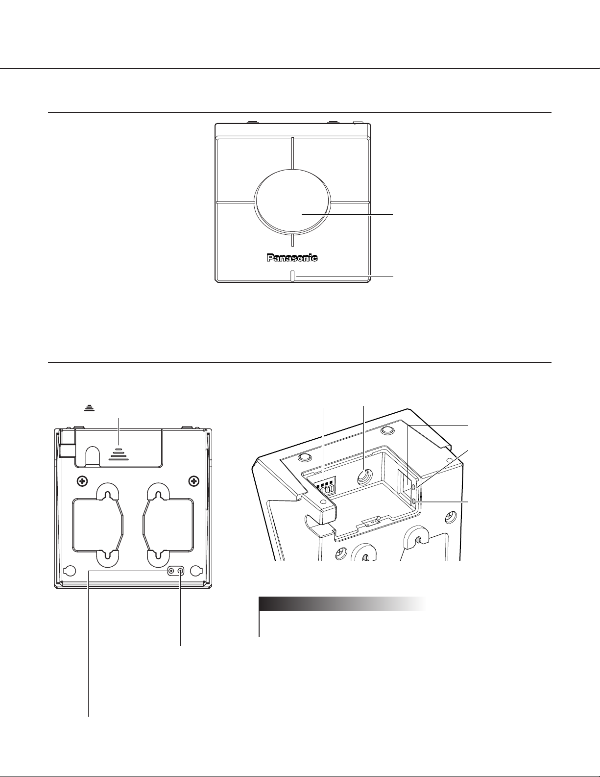
Front View
Dome cover
Power LED
You can select ON or OFF for
the LED on the “System” page.
(Refer to page 63.)
Rear View
HTML document initialization switch
All HTML documents return to the default settings (to the default settings of the latest upgraded firmware if the firmware has been
upgraded) when the AC adapter is plugged into an outlet while this switch is pressed and kept pressed for five seconds or more
after the plug is inserted.
Note:
It will take around 5 minutes to initialize all HTML documents. The power LED blinks during the initialization. It changes to steady
light after the initialization has been completed.
Setting reset switch
All settings return to the default settings when the AC adapter is plugged into an outlet while this switch is
pressed and kept pressed for five seconds or more after the plug is inserted.
Connector cover
To detach the connector cover, hold down
the part and slide it.
Alarm connector
Power plug connector
(Only use the AC adapter supplied)
Ethernet
connector
Link LED
(Lights up when
communication with
connected devices
becomes possible.)
Access LED
(Lights up when
accessing to the
network.)
Inside of the connector cover
Firmly insert the power plug of the AC adapter into the power plug
connector of the camera.
! Important
11
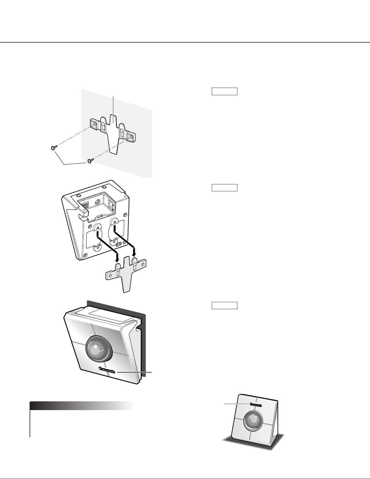
INST ALLA TIONS
This is an example of an installation onto a wall.
Install the wall-mounting bracket onto the wall
using the screws.
STEP1
Install the camera onto the wall-mounting bracket by referring to the illustration shown on the
left.
It is possible to install the camera upside down.
Install the camera in the upside down position
according to your needs.
Confirm that the Panasonic logo is in the position shown in the illustration.
If the logo is upside down, rotate the logo.
STEP3
STEP2
If the camera is placed on a desk, as shown in the illustration on the right, select "Desk top" for "Camera position" on
the "Basic setup" page.
Note
Logo
Screws
Wall-mounting bracket
Logo
12
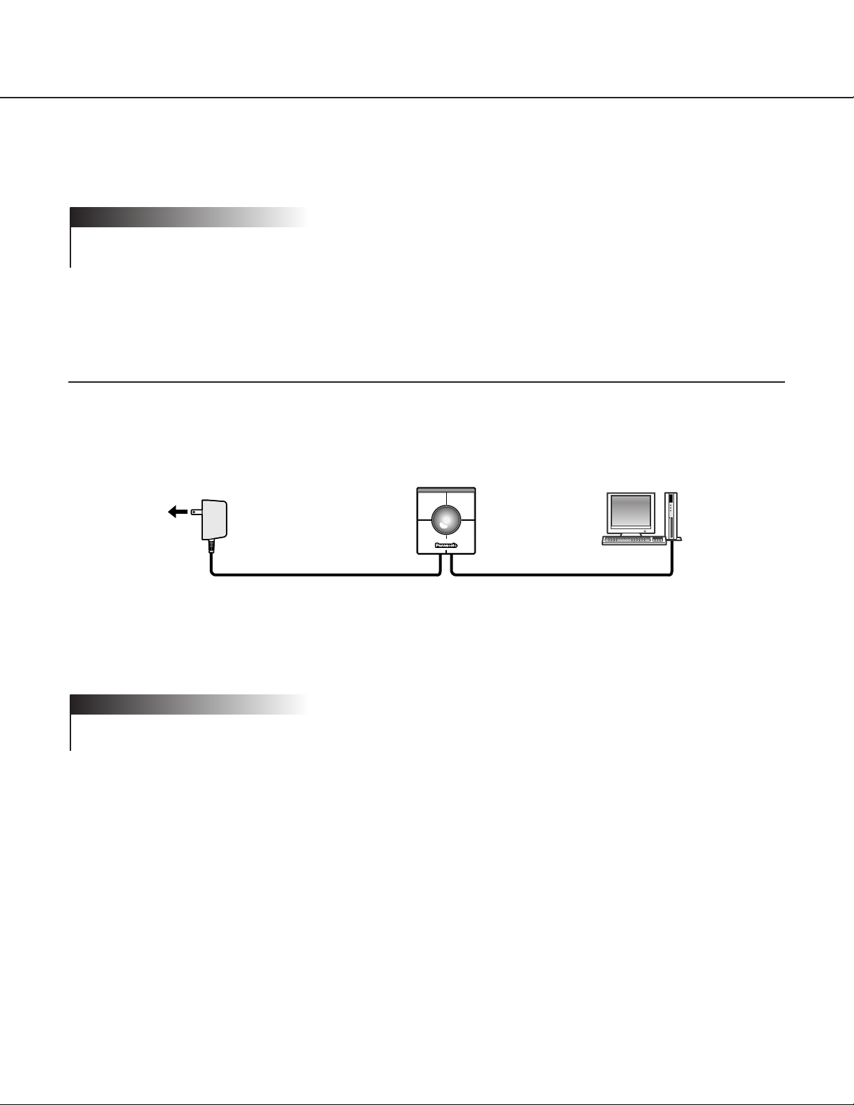
CONNECTIONS
Connection between a PC and This Camera (Connection type 1)
Connect the camera and the PC directly using an Ethernet cable when browsing the camera pictures or performing
the network settings of the camera.
< Connection example >
< Required cable >
Ethernet cable (category 5 cross cable)
• All cameras connected to the network must use their own exclusive AC adapter.
• Use only the specified Ethernet cable, category 5 cross cable.
! Important
Before starting the connections, confirm which type of connection meets your needs.
The following explanations are provided for each connection type.
Prepare the required hardware and cables for your connection type before starting the connections.
Before starting the connections, confirm that all the power switches of the camera, the ADSL/cable modem, the
switching hub and the PC are turned off, and that all power plugs are not connected to the outlet.
! Important
AC adapter
To an outlet
(120 V AC)
Ethernet cable
(category 5 cross cable)
13
Using with an Intranet (LAN)
(Connection type 2)
Connect the camera to an intranet (LAN) using an Ethernet switching hub or router when browsing camera pictures
of a camera installed in the same LAN (the intranet of a company or home).
< Connection example >
< Required hardware >
Ethernet switching hub or router
< Required cable >
Ethernet cable (category 5 straight cable)
• Use an Ethernet switching hub or router suitable for 10Base-T/100Base-TX.
• Install also a LAN card suitable for 10Base-T/100Base-TX on the PC.
• All cameras connected to the network must use their own exclusive AC adapter.
! Important
Ethernet
switching hub or router
LAN
AC adapter
To an outlet
(120 V AC)
AC adapter
To an outlet
(120 V AC)
14
CONNECTIONS
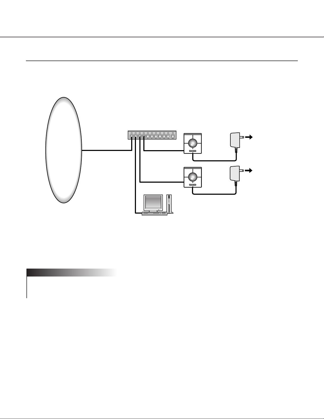
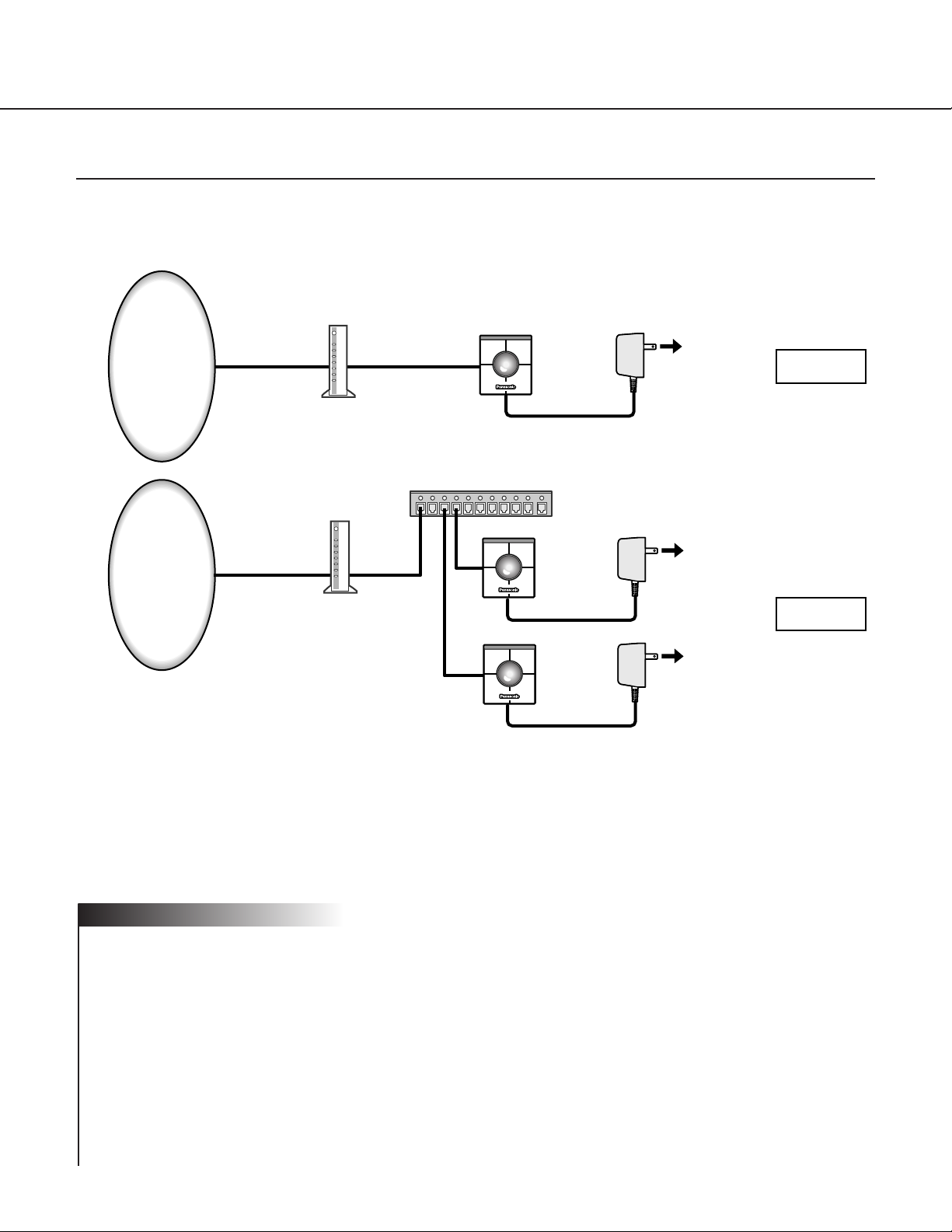
Using via the Internet (Connection type 3-4)
Connecting the camera to the Internet using an xDSL modem or a cable modem.
< Connection example >
< Required hardware >
• Cable modem or xDSL modem
• Broadband router
< Required cable >
Ethernet cable (category 5 straight cable)
• When the camera is connected using connection type 3 or 4, obtain the global IP address from the Internet service provider. Perform the settings of the camera by connecting the camera and the PC directly. (Refer to the
next page.)
• When the camera is connected using connection type 3, it is required to assign the global IP address to the camera. When the camera is connected using connection type 4, it is required to assign the global IP address to the
broadband router and to set the address translation. (Refer to page 26.).
• Use an Ethernet switching hub or a broadband router suitable for 10Base-T/100Base-TX.
Install also a LAN card suitable for 10Base-T/100Base-TX on the PC.
• All cameras connected to the network must use their own exclusive AC adapter.
• To use multiple cameras, it is necessary to set up the router and assign each camera with an HTTP port number. For further information about the assignment of the HTTP port number to the camera, refer to page 28. For
further information about the setup of the router, refer to the operating instructions of the router.
! Important
Connection of
a single camera
Cable modem
Cable line
Internet
Internet
Broadband router
Cable modem or
xDSL modem (1 port)
Cable line
or xDSL
line
AC adapter
To an outlet
(120 V AC)
AC adapter
To an outlet
(120 V AC)
AC adapter
To an outlet
(120 V AC)
Connection
type 3
Connection
type 4
15
SETUP
After completing the connections, it is necessary to set up the network of the PC and the camera.
To operate the camera connected in a network such as a LAN or the Internet, it is necessary to set up the network.
Use the provided "Panasonic IP Setup" software to set up the network of the camera. (Refer to the next page).
If the setup with the provided software fails, set up the PC and the camera separately. For further information, refer
to pages 18 - 28.
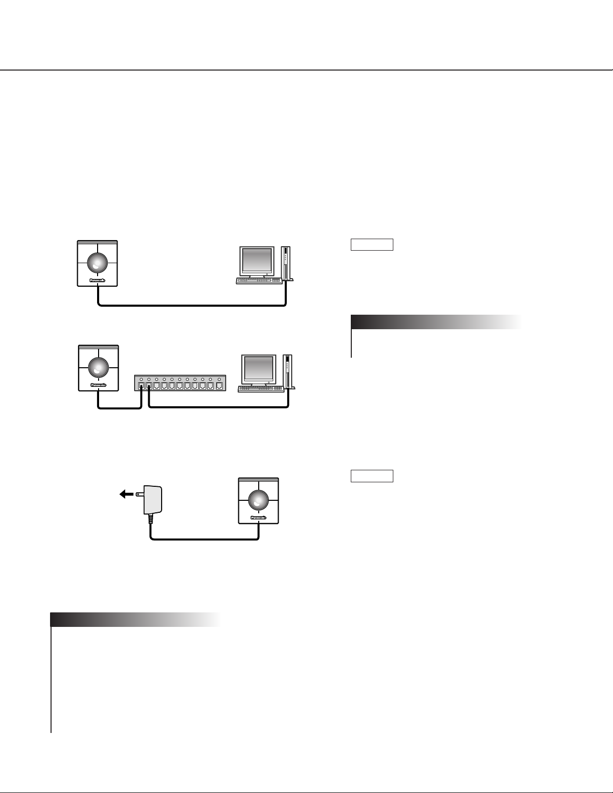
Preparations for the Setup
Prepare the following items before starting the network setup.
Connect the camera and the PC in either of the
ways shown on the left.
Use a category 5 cross cable if the camera
and the PC are connected directly.
! Important
STEP1
Turn on the power of the camera after the connection is made.
The power is supplied to the camera by connecting the AC adapter to an outlet.
After the power is supplied, it will take around 2
minutes before the camera can be operated.
STEP2
• When the power is supplied, the power LED lights up for around 80 seconds and then blinks for around 20 seconds. Then the camera performs one complete panning and tilting operation.
• Confirm that the power LED and the link LED are lit after the power is supplied.
If the power LED is not lit:
Confirm that the AC adapter is firmly plugged into both the camera and the outlet.
If the link LED is not lit:
Confirm that the Ethernet cable is inserted firmly. Confirm also that the cable type (straight / cross) corresponds
to the connection type.
Notes
Ethernet cable
(Category 5 cross cable)
Ethernet
switching hub
Ethernet cable
(Category 5 straight cable)
AC adapter
To an outlet
(120 V AC)
16
SETUP
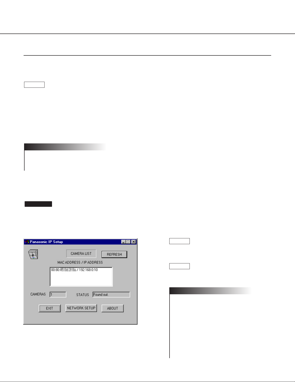
Setup with the Provided "Panasonic IP Setup"Software
Set up the network of the camera by using the "Panasonic IP Setup" software included on the CD-ROM provided
with the camera.
The "Panasonic IP Setup" starts up.
The MAC address and the IP address of the connected camera
will be displayed. (Click the “REFRESH” button if they are not
displayed.)
Screenshot 1
Click the MAC address/IP address of the camera to be set up.
Click the [NETWORK SETUP] button.
• When two or more cameras are connected,
the MAC addresses and the IP addresses of
all the connected cameras will be displayed.
• The “Panasonic IP Setup” software can recognize only those cameras in the same subnet.
• The updated MAC addresses and IP
addresses of all the connected cameras that
are in the same subnet will be displayed by
pressing the REFRESH button.
Notes
STEP3
STEP2
When the provided CD-ROM is inserted into the CD-ROM drive of the PC, the launcher software starts up and the
readme file is displayed.
Items included in the software
• SETUP
• Instructions
• MPEG-4 Installation
After reading the readme file, click the [SETUP] button.
• Double click "launch.exe" on the provided CD-ROM if the launcher software does not start up automatically.
• If a firewall (including software) exists, allow access to all UDP ports. Otherwise, it is impossible to use the
“Panasonic IP Setup” software.
Notes
STEP1
17
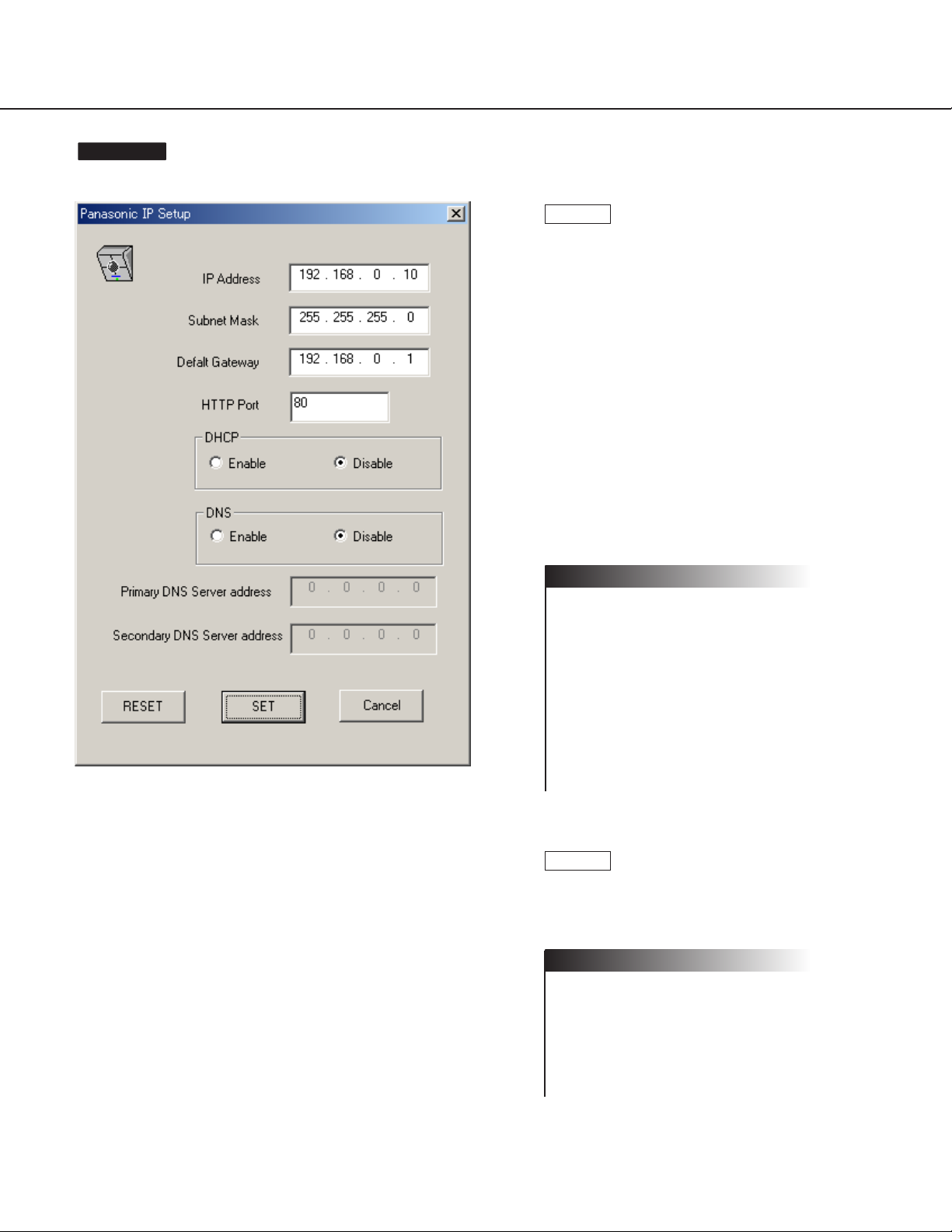
Set parameters for each item.
"IP Address"
"Subnet Mask"
"Default Gateway"
"HTTP Port"
Enter parameters depending on your environment.
For further information about the parameters,
refer to pages 27-28.
"DHCP"
"DNS"
Click the [Enable] radio button when using the
DHCP and the DNS.
When using the DNS function, enter the
“Primary DNS Server address” and the
“Secondary DNS Server address”.
• If DHCP is enabled although there is no
DHCP server in the network, check
“Disable” for DHCP in the “Panasonic IP
Setup” window.
• If DHCP is enabled, and the DHCP server
has not assigned an IP address yet,
“0.0.0.0” is displayed for the IP address. The
IP address of the camera will be displayed
after the DHCP server assigns one to the
camera.
Click the [SET] button after completing the setting.
It takes around 20 seconds to complete the
settings of the camera after the [SET] button
is pressed. If the AC adapter or the Ethernet
cable is detached before the settings are completed, the settings may not be performed correctly.
! Important
STEP5
Notes
STEP4
The setup window appears.
Screenshot 2
18
SETUP
Begin the setup when the PC is in the same condition as just
after the startup.
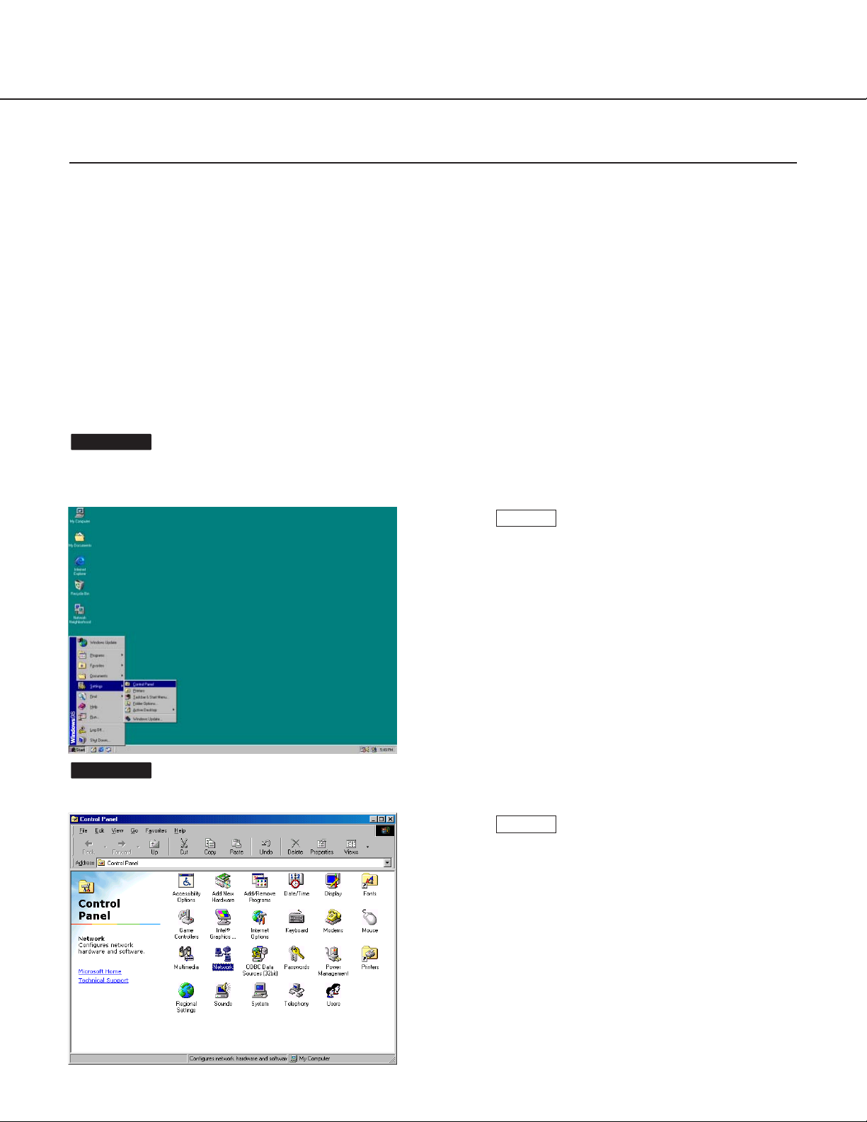
The "Control Panel" window appears.
Screenshot 2
Screenshot 1
Select "Control Panel" ([Start] - [Settings] [Control Panel]).
STEP1
Click once to select the [Network] icon.
STEP2
Network Setup of the PC
To set up the network of the PC, first change the TCP/IP settings of the PC to match them to the default settings of
the camera. The following are the default network settings of the camera.
• IP address: 192.168.0.10
• Subnet mask: 255.255.255.0
• Default gateway: 192.168.0.1
To access the camera, the IP address of the PC should be "192.168.0.XXX" (where XXX should be a number from
2 to 254 except 1 and 10). In case the IP address of the camera is set with the "Panasonic IP Setup" software, perform the network setting of the PC according to the network environment.
The settings differ depending on which OS is installed on the PC. Confirm which OS is installed on your PC, and
proceed with the settings corresponding to your OS.
Using Windows 98 SE
The following procedures are examples when using Windows 98 SE. You can proceed in the same way when using
Windows Me.
19
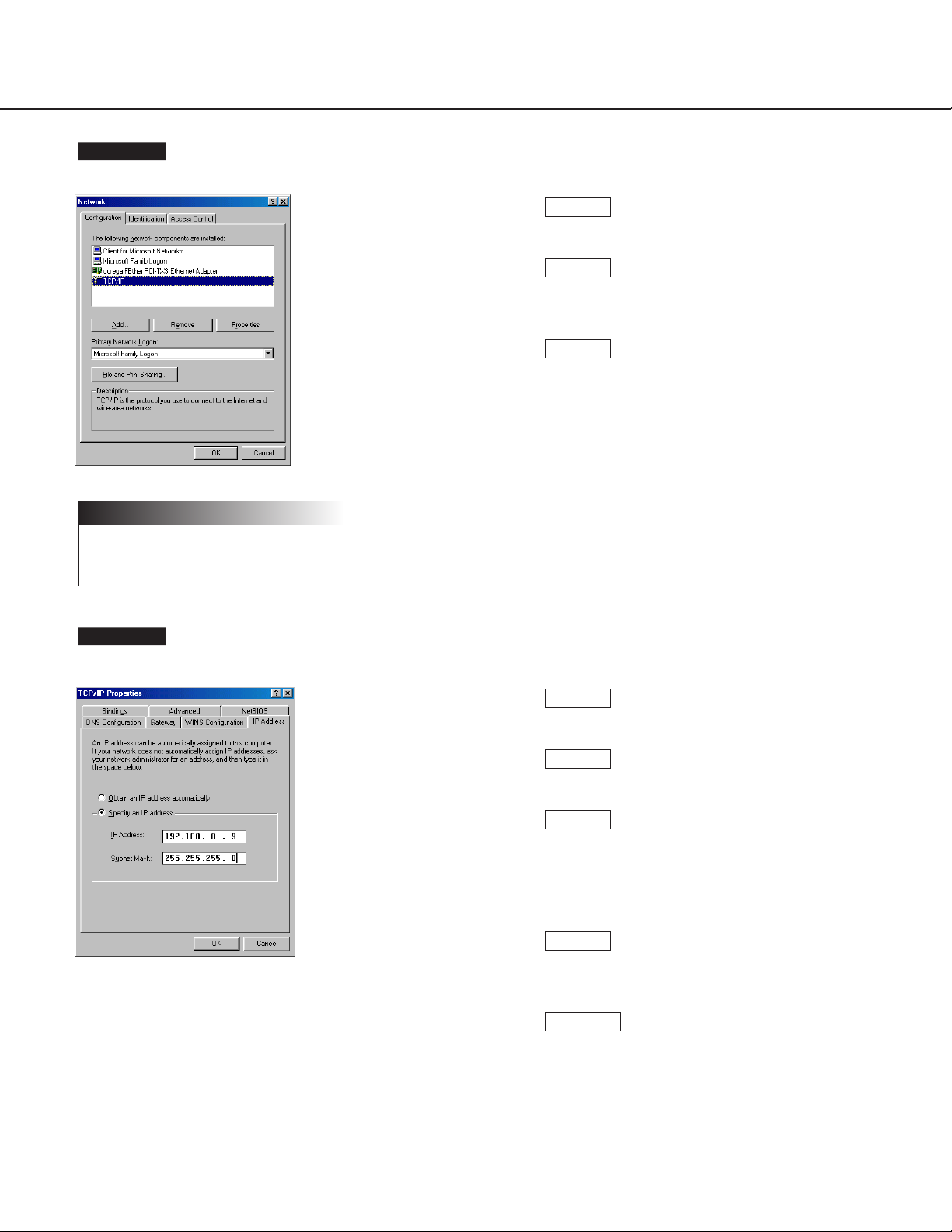
The "Network" window appears.
If the “TCP/IP” item is not displayed, refer to the operating
instructions of the OS and follow the procedures to install the
TCP/IP.
The "TCP/IP Properties" window appears.
Screenshot 4
Note
Screenshot 3
Click the [Configuration] tab.
Click to select the TCP/IP protocol of the currently used network card.
Click the [Properties] button.
STEP5
STEP4
STEP3
Click the [IP Address] tab.
Click the "Specify an IP address" radio button.
Enter the IP address and the subnet mask as
follows.
• IP Address: 192.168.0.9
• Subnet Mask: 255.255.255.0
Click the [OK] button, and the window closes.
Restart the PC to make the IP address valid.
STEP10
STEP9
STEP8
STEP7
STEP6
20
SETUP
Using Windows 2000
The following procedures are examples when using Windows 2000. You can proceed in the same way when using
Windows NT.
Log in as one of the administrators before beginning the setup.
! Important
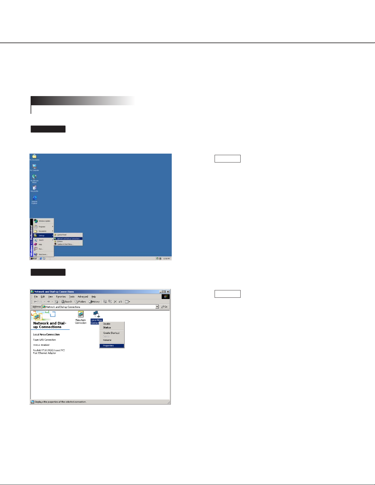
Begin the setup when the PC is in the same condition as just
after the startup.
The "Network and Dial-up Connections" window appears.
Screenshot 2
Screenshot 1
Select "Network and Dial-up Connections"
([Start] - [Settings] - [Network and Dial-up
Connections]).
STEP1
Click the right mouse button on the "Local Area
Connection" icon, and select "Properties" from
the pop-up menu.
STEP2
21
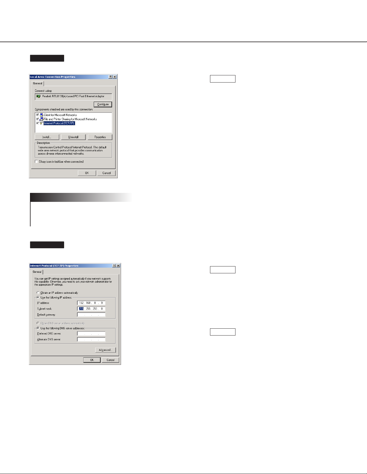
The "Local Area Connection Properties" window appears.
If the “Internet Protocol (TCP/IP)” item is not displayed, refer to
the operating instructions of the OS and follow the procedures
to install the TCP/IP.
The "Internet Protocol (TCP/IP) Properties" window appears.
Screenshot 4
Note
Screenshot 3
Click to select "Internet Protocol (TCP/IP)", and
then click the [Properties] button.
STEP3
Click the "Use the following IP address" radio
button and enter the IP address and the subnet
mask as follows.
• IP address: 192.168.0.9
• Subnet mask: 255.255.255.0
Click the [OK] button, and the window closes.
STEP5
STEP4
22
SETUP
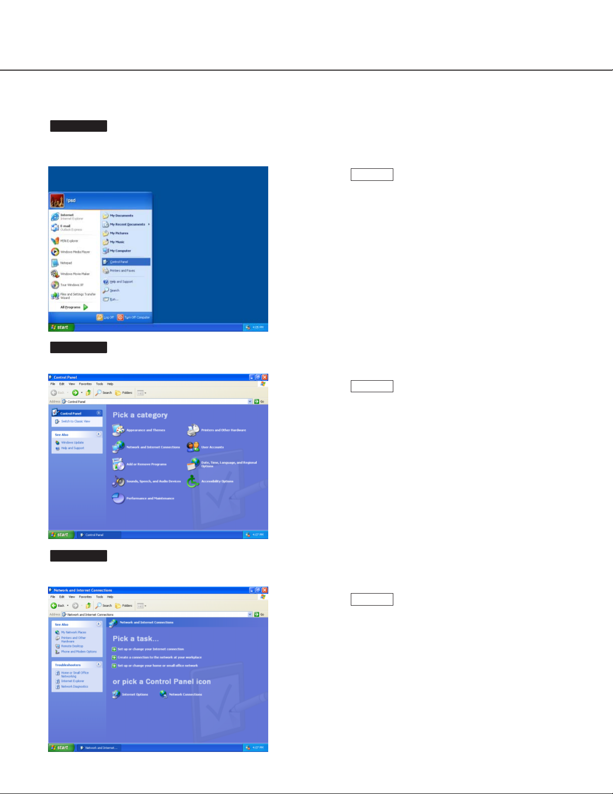
Using Windows XP (Category View)
Begin the setup when the PC is in the same condition as just
after the startup.
The "Control Panel" window appears.
The "Network and Internet Connections" window appears.
Screenshot 3
Screenshot 2
Screenshot 1
Select "Control Panel" ([Start] - [Control Panel]).
STEP1
Double click the "Network and Internet
Connections" icon.
STEP2
Double click the "Network Connections" icon.
STEP3
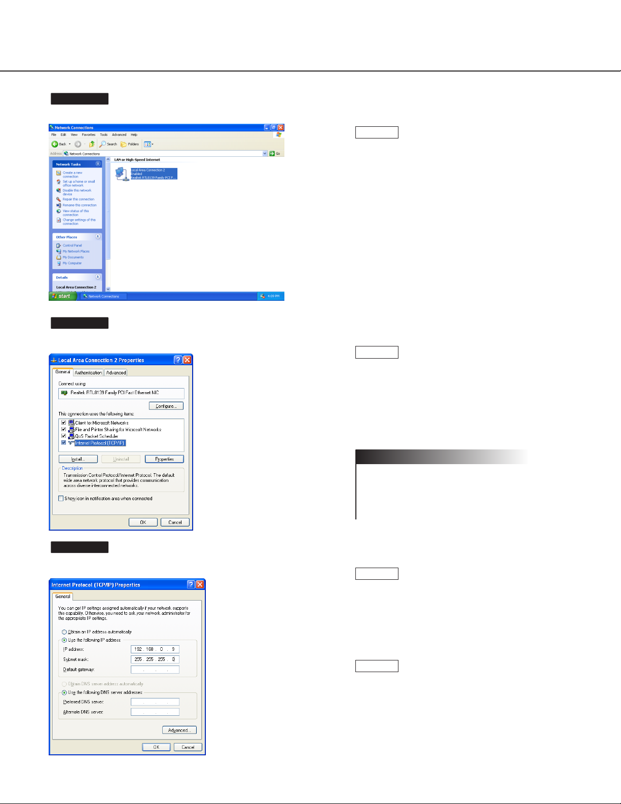
23
The "Network Connections" window appears.
The "Local Area Connection Properties" window appears.
The "Internet Protocol (TCP/IP) Properties" window appears.
Screenshot 6
Screenshot 5
Screenshot 4
Click to select "Local Area Connection", and
then click "Change settings of this connection"
in the "Network Tasks" menu.
STEP4
Click to select "Internet Protocol (TCP/IP)", and
then click the [Properties] button.
If the “Internet Protocol (TCP/IP)” item is not
displayed, refer to the operating instructions of
the OS and follow the procedures to install the
TCP/IP.
Note
STEP5
Click the "Use the following IP address" radio
button and enter the IP address and the subnet
mask as follows.
• IP address: 192.168.0.9
• Subnet mask: 255.255.255.0
Click the [OK] button, and the window closes.
STEP7
STEP6
 Loading...