

Page 1
Operating Instructions
WV-SFV481
WV-SFN480
Network Camera
Model No. WV-SFV481
WV-SFN480
This manual covers the models: WV-SFV481 and WV-SFN480.
Before attempting to connect or operate this product, please read these instructions
carefully and save this manual for future use.
Page 2

SFV481
SF N 4 8 0
Preface
Preface
About the user manuals
There are 3 sets of operating instructions as follows.
• Operating Instructions (this document): Explains how to perform the settings and how to operate this
camera.
• Important Information: Provides information about the cautions required for safely using and installing this
camera.
• Installation Guide: Explains how to install and connect devices.
The screens used in these operating instructions show the case of WV-SFV481. Depending on the model
used, the screens shown in the explanations may differ to the actual camera screens.
About notations
The following notations are used when describing the functions limited for specified models.
The functions without the notations are supported by all models.
: The functions with this notation are available when using the model WV-SFV481.
: The functions with this notation are available when using the model WV-SFN480.
Trademarks and registered trademarks
• Microsoft, Windows, Windows Vista, Windows Media, Internet Explorer, and ActiveX are either registered
trademarks or trademarks of Microsoft Corporation in the United States and/or other countries.
• Microsoft product screen shot(s) reprinted with permission from Microsoft Corporation.
• iPad, iPhone, iPod touch, and QuickTime are trademarks of Apple Inc., registered in the U.S. and other
countries.
• Android is a trademark of Google Inc.
• Firefox is a registered trademark of the Mozilla Foundation.
• SDXC Logo is a trademark of SD-3C, LLC.
• All other trademarks identified herein are the property of their respective owners.
Abbreviations
The following abbreviations are used in these operating instructions.
Microsoft® Windows® 8.1 is described as Windows 8.1.
Microsoft® Windows® 8 is described as Windows 8.
Microsoft® Windows® 7 is described as Windows 7.
Microsoft® Windows Vista® is described as Windows Vista.
Windows® Internet Explorer® 11, Windows® Internet Explorer® 10, Windows® Internet Explorer® 9, Windows
Internet Explorer® 8 and Windows® Internet Explorer® 7 are described as Internet Explorer.
SDXC/SDHC/SD memory card is described as SD card or SD memory card.
Universal Plug and Play is described as UPnP™.
®
2 Operating Instructions
Page 3
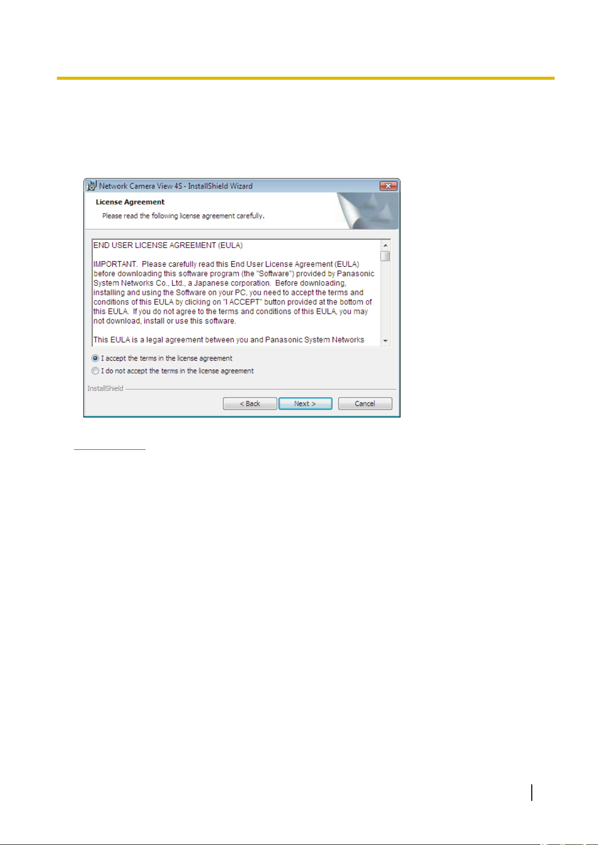
Viewer software
It is necessary to install the viewer software “Network Camera View 4S” (ActiveX®) to display images on a PC.
This software can be installed directly from the camera or by selecting the [Install] button next to [Viewer
Software] on the menu of the CD-ROM provided, and then following the on-screen instructions.
Preface
IMPORTANT
• The default setting of “Automatic installation” is “On”. Follow the instructions on page 229 when the
message is displayed on the information bar of the browser.
• When the “Live” page is displayed for the first time, the install wizard of the ActiveX control required to
display images from the camera will be displayed. Follow the instructions of the wizard.
• When the install wizard is displayed again even after completing the installation of the ActiveX, restart
the PC.
• The viewer software used on each PC should be licensed individually. The number of installations of
the viewer software from the camera can be checked on the [Upgrade] tab of the “Maintenance” page
(®page 204). Refer to your dealer for the software licensing.
Operating Instructions 3
Page 4

Table of Contents
Table of Contents
1 Monitor images on a PC ..........................................................................7
1.1 Monitor images from a single camera .............................................................................7
1.2 About live image types .....................................................................................................9
1.2.1 Type of images that can be displayed according to the image setting .............................9
1.2.2 About image capture mode ............................................................................................10
1.3 Image types .....................................................................................................................11
1.4 About image types and available functions .................................................................15
1.4.1 About available resolutions ............................................................................................16
1.5 About the “Live” page ....................................................................................................19
1.6 Monitor images from multiple cameras ........................................................................25
2 Monitor images on a cellular phone/mobile terminal .........................27
2.1 Monitor images on a cellular phone ..............................................................................27
2.2 Monitor images on a mobile terminal ............................................................................29
3 Record images on the SD memory card manually .............................39
4 Action at an alarm occurrence ..............................................................41
4.1 Alarm type ........................................................................................................................41
4.2 Action at an alarm occurrence .......................................................................................41
5 Transmit images onto an FTP server ...................................................43
5.1 Transmit an alarm image at an alarm occurrence (Alarm image
transmission) ...................................................................................................................43
5.2 Transmit images at a designated interval or period (FTP periodic image
transmission) ...................................................................................................................43
5.3 Save images on the SD memory card when images fail to transmit using the FTP
periodic image transmission function ..........................................................................44
6 Display the log list .................................................................................45
7 Playback of images on the SD memory card ......................................49
7.1 Playback “JPEG(1)”/“JPEG(2)” images saved to the SD memory card ....................49
7.2 Playback “H.264(1)”/“H.264(2)” images saved to the SD memory card ....................52
8 About the network security ...................................................................55
8.1 Equipped security functions ..........................................................................................55
9 Display the setup menu from a PC .......................................................56
9.1 How to display the setup menu .....................................................................................56
9.2 How to operate the setup menu .....................................................................................58
9.3 About the setup menu window ......................................................................................60
10 Configure the basic settings of the camera [Basic] ...........................62
10.1 Configure the basic settings [Basic] .............................................................................62
10.2 Configure the Internet settings [Internet] .....................................................................68
10.3 Configure the settings relating to the SD memory card [SD memory card] ..............70
10.4 Access copy images saved on the SD memory card onto the PC [SD memory card
images] .............................................................................................................................76
10.5 Configure the directory of the PC that images will be downloaded to [Log] ............92
4 Operating Instructions
Page 5

Table of Contents
11 Configure the settings relating to images and audio [Image/
Audio] ......................................................................................................94
11.1 Configure the settings relating to the image capture mode [JPEG/H.264] ................94
11.2 Configure the settings relating to JPEG images [JPEG/H.264] ..................................95
11.3 Configure the settings relating to H.264 images [JPEG/H.264] ..................................97
11.4 Configure the settings relating to the camera operations [Cam. Function] ............104
11.5 Configure the settings relating to image adjust, back focus, preset position, privacy
zone and VIQS [Image/Position] ..................................................................................106
11.5.1 Configure the settings relating to image quality (“Image adjust” setup menu) .............107
11.5.2 Set mask areas ............................................................................................................112
11.5.3 Configure the preset positions (Preset position setup menu) .......................................115
11.5.4 Configure the preset positions (Initial position setup menu) .........................................117
11.6 Back focus setting (“Back focus” setup menu) .........................................................120
11.7 Configure the settings relating to the privacy zone (“Privacy zone” setup
menu) .............................................................................................................................121
11.8 Configure the VIQS setting ..........................................................................................123
11.9 Configure the VIQS area ...............................................................................................126
11.10 Configure the settings relating to audio [Audio] .......................................................128
12 Configure the multi-screen settings [Multi-screen] ..........................132
13 Configure the alarm settings [Alarm] .................................................134
13.1 Configure the settings relating to the alarm action [Alarm] .....................................134
13.2 Configure the settings relating to the alarm output terminal [Alarm] ......................136
13.3 Change the AUX name [Alarm] ....................................................................................136
13.4 Configure the settings relating to the camera action on alarm occurrence
[Alarm] ............................................................................................................................137
13.4.1 Configure settings relating to alarm E-mail notifications ..............................................138
13.4.2 Configure settings relating to FTP transmissions of alarm images ..............................139
13.4.3 Configure settings relating to recording to an SD memory card when an alarm
occurs ...........................................................................................................................141
13.4.4 Configure settings relating to Panasonic alarm protocol notification when an alarm
occurs ...........................................................................................................................142
13.4.5 Configure settings relating to HTTP alarm notification when an alarm occurs .............143
13.4.6 Configure settings relating to camera actions on alarm action .....................................143
13.5 Configure the VMD settings [VMD area] .....................................................................144
13.5.1 Set the VMD areas [VMD area] ....................................................................................147
13.6 Configuration of the settings relating to alarm notification [Notification] ..............149
13.6.1 Configure the settings relating to Panasonic alarm protocol ........................................150
13.6.2 Configure the settings relating to HTTP alarm notification ...........................................152
14 Configure the settings relating to the authentication [User
mng.] .....................................................................................................154
14.1 Configure the settings relating to the user authentication [User auth.] ..................154
14.2 Configure the settings relating to the host authentication [Host auth.] ..................155
14.3 Configure the settings relating to the priority stream [System] ...............................156
15 Configuring the network settings [Network] .....................................159
15.1 Configure the network settings [Network] ..................................................................159
15.2 Configure advanced network settings [Advanced] ...................................................163
15.2.1 Configure the settings related to sending E-mails ........................................................164
15.2.2 Configure the settings related to FTP transmission .....................................................166
15.2.3 Configure the settings relating to the NTP server ........................................................170
15.2.4 Configure the UPnP settings ........................................................................................172
Operating Instructions 5
Page 6

Table of Contents
15.2.5 Configure the HTTPS settings ......................................................................................173
15.2.6 Configure the settings relating to DDNS ......................................................................175
15.2.7 Configure the settings relating to SNMP ......................................................................175
15.2.8 Configure the Diffserv settings .....................................................................................176
15.3 How to configure HTTPS settings ...............................................................................177
15.3.1 Generation of the CRT key (SSL encryption key) ........................................................178
15.3.2 Generation of the self-signed certificate (security certificate) .......................................179
15.3.3 Generation of CSR (Certificate Signing Request) ........................................................181
15.3.4 Installation of the server certificate ...............................................................................182
15.3.5 Configuration of the connection protocol ......................................................................183
15.4 Access the camera using the HTTPS protocol ..........................................................184
15.4.1 Install the security certificate ........................................................................................184
15.5 How to configure the settings relating to DDNS ........................................................191
15.5.1 Configuration of the DDNS service (Example of the “Viewnetcam.com” service) ........192
15.5.2 When using the “Viewnetcam.com” service .................................................................193
15.5.3 Procedure to register information for the “Viewnetcam.com” service ...........................194
15.5.4 Checking the information registered for the “Viewnetcam.com” service ......................195
15.5.5 When using “Dynamic DNS Update” ............................................................................195
15.5.6 When using “Dynamic DNS Update(DHCP)” ...............................................................196
16 Configure the settings relating to the schedules [Schedule] ..........197
16.1 How to set the schedules .............................................................................................200
16.2 How to delete the set schedule ....................................................................................202
17 Maintenance of the camera [Maintenance] ........................................204
17.1 Check the system log [System log] .............................................................................204
17.2 Upgrade the firmware [Upgrade] .................................................................................204
17.3 Check the status [Status] .............................................................................................206
17.4 Reset the settings/Reboot the camera [Default reset] ...............................................207
17.5 Settings data/backing up or restoring logs [Data] .....................................................208
18 Using the CD-ROM ...............................................................................211
18.1 About the CD launcher .................................................................................................211
18.2 Installing Panasonic “IP Setting Software” ................................................................212
18.3 Installing the manuals ..................................................................................................213
18.4 Installing the Viewer software ......................................................................................213
18.5 Configure the network settings of the camera using the Panasonic “IP Setting
Software” .......................................................................................................................214
19 About the displayed system log .........................................................217
20 Troubleshooting ...................................................................................221
21 Directory structure of drive B .............................................................231
6 Operating Instructions
Page 7
1 Monitor images on a PC
1 Monitor images on a PC
The following are descriptions of how to monitor images from the camera on a PC.
1.1 Monitor images from a single camera
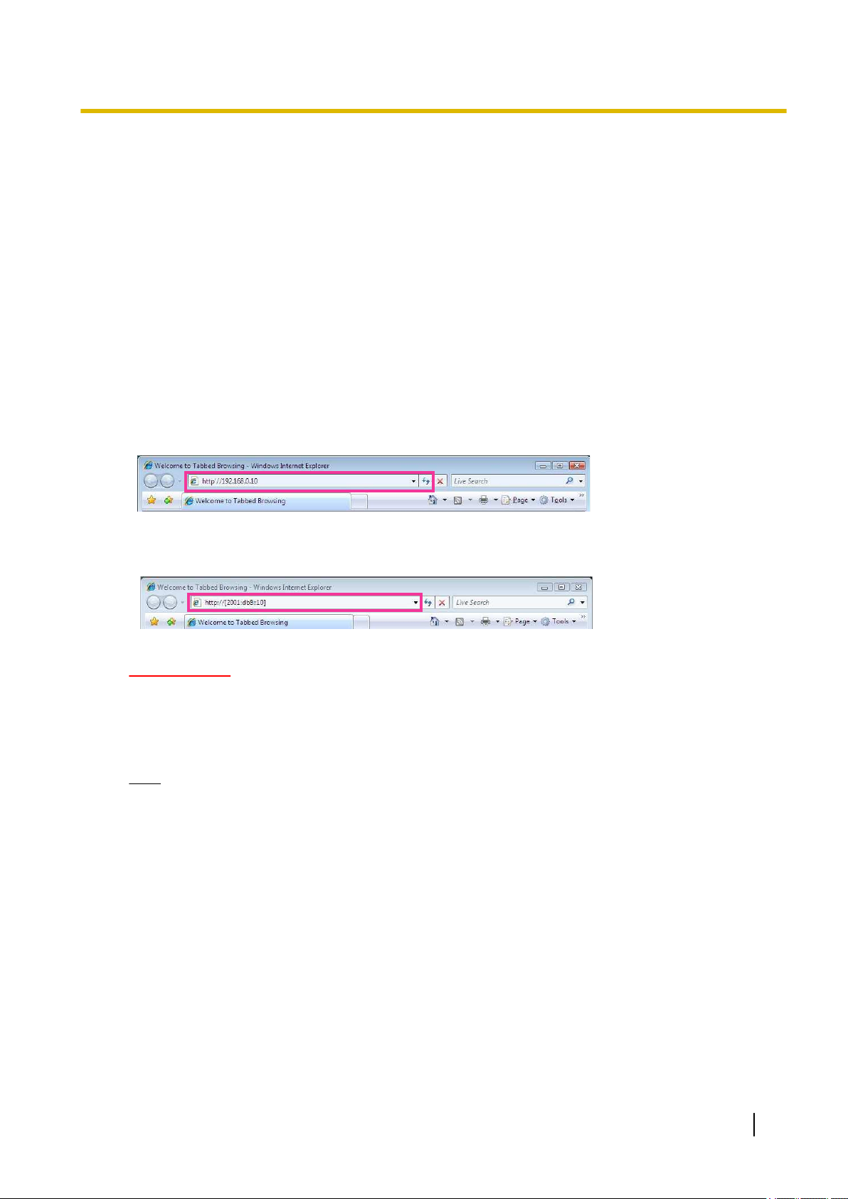
1. Start up the web browser.
2. Enter the IP address designated using the Panasonic “IP Setting Software” in the address box of the
browser.
• Example when entering an IPv4 address: http://URL registered using IPv4 address
http://192.168.0.10/
• Example when entering an IPv6 address: http://[URL registered using IPv6 address]
http://[2001:db8::10]/
<Example of IPv4 access>
<Example of IPv6 access>
IMPORTANT
• When the HTTP port number is changed from “80”, enter “http://IP address of the camera + : (colon)
+ port number” in the address box of the browser. (Example: http://192.168.0.11:8080)
• When the PC is in a local network, configure the proxy server setting of the web browser (under
[Internet Options...] under [Tools] of the menu bar) to bypass the proxy server for the local address.
Note
• Refer to page 184 for further information about the case in which “HTTPS” is selected for
“HTTPS” - “Connection” on the [Advanced] tab of the “Network” page (®page 159).
Operating Instructions 7
Page 8
1 Monitor images on a PC
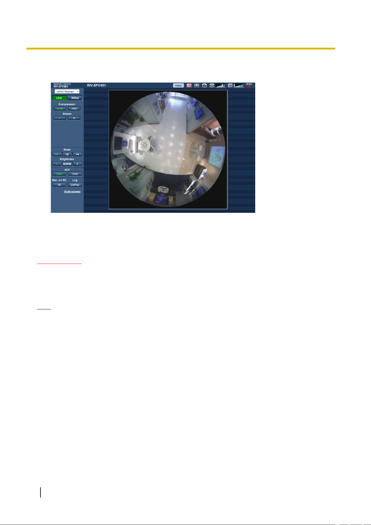
3. Press the [Enter] key on the keyboard.
→ The “Live” page will be displayed. Refer to page 19 for further information about the “Live” page.
When “On” is selected for “User auth.”, the authentication window will be displayed before displaying live
images for the user name and password entries. The default user name and password are as follows.
User name: admin
Password: 12345
IMPORTANT
• To enhance the security, change the password for the user name “admin”. It is recommended to change
this password periodically.
• When displaying multiple H.264 images on a PC, images may not be displayed depending on the
performance of the PC.
Note
• The maximum number of concurrent access user is 14 including users who is receiving H.264 images
and users who are receiving JPEG images. Depending on the set values for “Bandwidth control(bit
rate)” and “Max bit rate (per client)”, the maximum concurrent access number may be 14 or less users.
When 14 users are concurrently accessing, the access limit message will be displayed for users who
subsequently attempt to access. When “Multicast” is selected for “Transmission type” of “H.264”, only
the first user who accessed to monitor H.264 images will be included in the maximum number. The
second and subsequent users who are monitoring H.264 images will not be included in the maximum
number.
• When “On” is selected for “H.264 transmission” (®page 99), H.264 images will be displayed. When
“Off” is selected, a JPEG image will be displayed. It is possible to display a JPEG image even when
“On” is selected for “H.264 transmission”. In this case, the refresh interval of JPEG images will be
limited to 5fps.
• The refresh interval may become longer depending on a network environment, PC performance,
photographic subject, access traffic, etc.
<Refresh interval of JPEG images>
When “On” is selected for “H.264 transmission”
max. 5fps
When “Off” is selected for “H.264 transmission”
Becomes as follows depending on the setting for “Image capture mode”.
– 4M Fisheye: max. 30fps
8 Operating Instructions
Page 9

1 Monitor images on a PC
– 9M Fisheye/Double Panorama/Panorama/Quad PTZ/Single PTZ/4M Fisheye + Double
Panorama/4M Fisheye + Panorama/4M Fisheye + Quad PTZ: max. 15fps
– 8M Fisheye + Double Panorama/8M Fisheye + Panorama/8M Fisheye + Quad PTZ: max. 6fps
Note that JPEG images cannot be displayed when Quad stream is selected.
1.2 About live image types
The type of images displayed on the “Live” page can be selected using “Image capture mode” on the [JPEG/
H.264] tab of the “Image/Audio” page of the setup menu. (®page 94)
Configure the type, operation, and resolution of live images on this section.
1.2.1 Type of images that can be displayed according to the image
setting
There are 3 types of settings for Image capture mode: “1 Monitor”, “2 Monitor”, and “Quad stream”. The type
of images that can be displayed and the supported mounting positions differ for each type. Check which images
can be displayed in the following table.
Refer to page 10 for further information about “Image capture mode”.
Refer to page 11 for information about each image.
Image capture mode
type
1 Monitor
This type transmits 1
type of image.
2 Monitor
This type transmits 2
types of images.
Quad stream
This type transmits 4
types of images with H.
264 and can also
transmit a single screen
image containing the 4
types of images
combined together.
Image capture mode Image types Mounting positions
9M Fisheye
4M Fisheye
Double Panorama Double Panorama ceiling
Panorama Panorama wall
Quad PTZ Quad PTZ ceiling, wall
Single PTZ Single PTZ ceiling, wall
8M Fisheye + Double
Panorama
4M Fisheye + Double
Panorama
8M Fisheye + Panorama
4M Fisheye + Panorama
8M Fisheye + Quad PTZ
4M Fisheye + Quad PTZ
Quad stream Quad stream (each
Fisheye ceiling, wall
*1
Fisheye, Double
Panorama
Fisheye, Panorama wall
Fisheye, Quad PTZ ceiling, wall
stream with Single PTZ),
Quad PTZ
ceiling
*1
ceiling
Operating Instructions 9
Page 10

1 Monitor images on a PC
*1
Ceiling mounting may also be possible depending on the mounting conditions.
1.2.2 About image capture mode
The maximum image capture size that can be configured is 9 megapixel (2992(H)x2992(V)).
The following types of images can be transmitted by each mode.
Image capture
mode
Description
9M Fisheye Fisheye images are transmitted. (Max. 15fps)
The maximum image capture size that can be configured is 9 megapixel (2992
(H)x2992(V)).
4M Fisheye Fisheye images are transmitted. (Max. 30fps)
The maximum image capture size that can be configured is 4 megapixel (2048
(H)x2048(V)).
Double Panorama Double Panorama images are transmitted. (Max. 15fps)
The maximum image capture size that can be configured is 3.5 megapixel (2560
(H)x1440(V)).
Panorama Panorama images are transmitted. (Max. 15fps)
The maximum image capture size that can be configured is 3.5 megapixel (2560
(H)x1440(V)).
Quad PTZ Quad PTZ images are transmitted. (Max. 15fps)
The maximum image capture size that can be configured is 5 megapixel (2560
(H)x1920(V)).
Single PTZ Single PTZ images are transmitted. (Max. 15fps)
The maximum image capture size that can be configured is 5 megapixel (2560
(H)x1920(V)).
8M Fisheye +
Double Panorama
Fisheye images and Double Panorama can be transmitted at the same time. (Max.
7.5fps)
The maximum image capture size that can be configured for Fisheye images is 8
megapixel (2816(H)x2816(V)), and for Double Panorama images is 1 megapixel (1280
(H)x720(V)).
4M Fisheye +
Double Panorama
8M Fisheye +
Panorama
10 Operating Instructions
Fisheye images and Double Panorama images can be transmitted at the same time.
(Max. 15fps)
The maximum image capture size that can be configured for Fisheye images is 4
megapixel (2048(H)x2048(V)), and for Double Panorama images is 1 megapixel (1280
(H)x720(V)).
Fisheye images and Panorama images can be transmitted at the same time. (Max.
7.5fps)
The maximum image capture size that can be configured for Fisheye images is 8
megapixel (2816(H)x2816(V)), and for Panorama images is 1 megapixel (1280
(H)x720(V)).
Page 11
1 Monitor images on a PC
Image capture
mode
4M Fisheye +
Panorama
8M Fisheye +
Quad PTZ
4M Fisheye +
Quad PTZ
Quad stream 4 types of Single PTZ images can be transmitted. (max. 15fps)
Fisheye images and Panorama images can be transmitted at the same time. (Max.
15fps)
The maximum image capture size that can be configured for Fisheye images is 4
megapixel (2048(H)x2048(V)), and for Panorama images is 1 megapixel (1280
(H)x720(V)).
Fisheye images and Quad PTZ images can be transmitted at the same time. (Max.
7.5fps)
The maximum image capture size that can be configured for Fisheye images is 8
megapixel (2816(H)x2816(V)), and for Quad PTZ images is 1.3 megapixel (1280
(H)x960(V)).
Fisheye images and Quad PTZ images can be transmitted at the same time. (Max.
15fps)
The maximum image capture size that can be configured for Fisheye images is 4
megapixel (2048(H)x2048(V)), and for Quad PTZ images is 1.3 megapixel (1280
(H)x960(V)).
A single screen image containing the 4 types of images combined together can also
be transmitted. (max. 5fps)
Only H.264 images can be sent.
The maximum image capture size that can be configured for Single PTZ (Quad stream)
is 1.3 megapixel (1280(H)x960(V)), and for Quad stream is 5 megapixel (2560
(H)x1920(V)).
Description
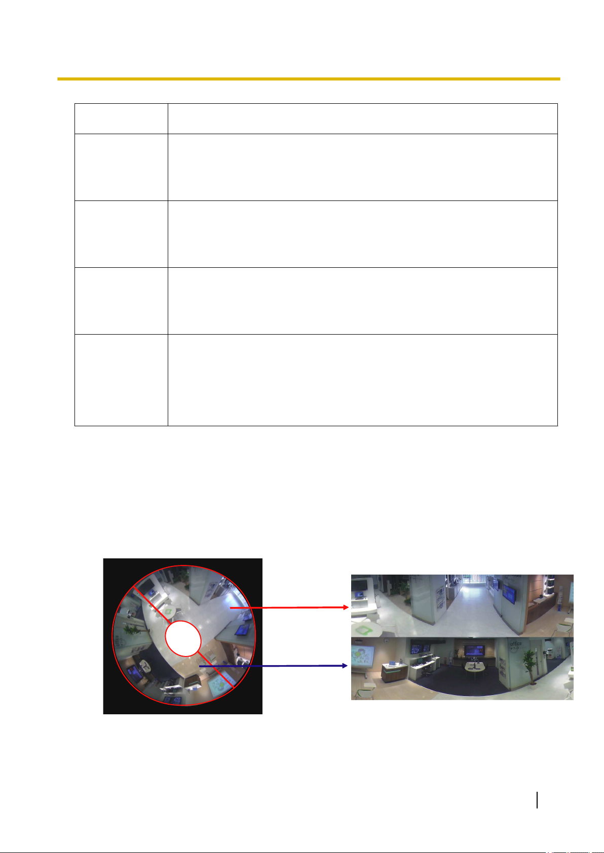
1.3 Image types
1. Double Panorama
In Double Panorama, the panorama image is displayed with distortion correction performed on a 180° image
for half of a fisheye image. Note that the center of a fisheye image is a blind spot and it is not displayed in the
fisheye image.
Note that the center of a fisheye image is a blind spot and it is not displayed in the fisheye image.
To divide the screen left-to-right or top-to-bottom, refer to the information in the Installation Guide and rotate
the image 45° to the left or right using the image rotation gear.
Operating Instructions 11
Page 12
1
3
2
4
1
3
2
4
1 Monitor images on a PC
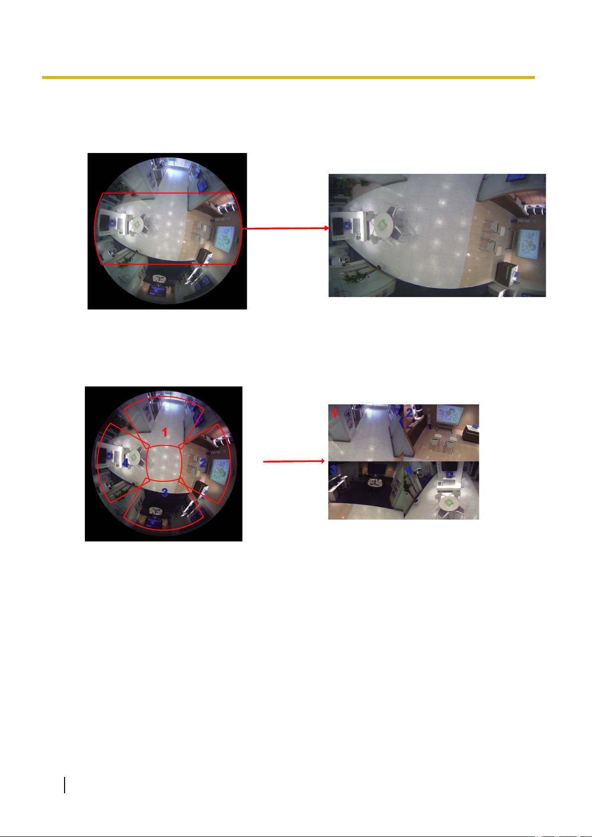
2. Panorama
In Panorama, the panorama image is displayed with distortion correction performed on the 180° horizontal
angle view part of the center of a fisheye image.
3. Quad PTZ
In the Quad PTZ screen, distortion in 4 fisheye images are corrected and the corrected images are displayed
together.
When an image is clicked by the mouse, the clicked position becomes the center of the image (Click &
Centering).
The display position of images can also be changed from the fisheye control screen.
12 Operating Instructions
Page 13
1
3
2
4
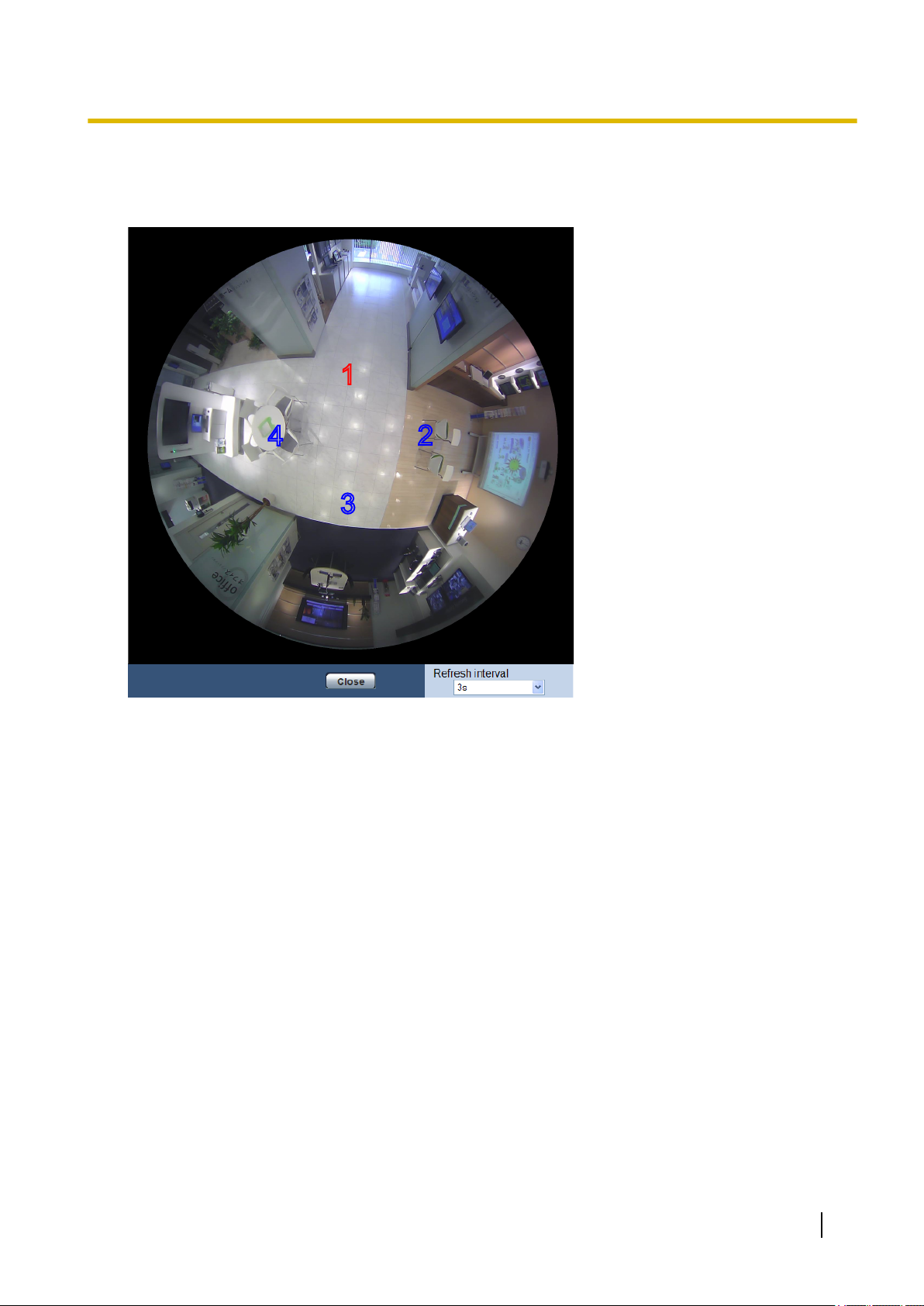
1 Monitor images on a PC
Fisheye Control
When the [Fisheye Control] button is clicked on the Quad PTZ or Single PTZ screen, the “Fisheye Control”
window is displayed.
From this window, the image position of each screen number can be changed.
By dragging and dropping the number icon on the screen onto the image, you can change the center of the
image to where the icon was dropped.
The red number icon is the selected number.
Select the “Refresh interval” value of “Fisheye Control” images from the following.
1s/ 3s/ 5s/ 10s/ 30s/ 60s
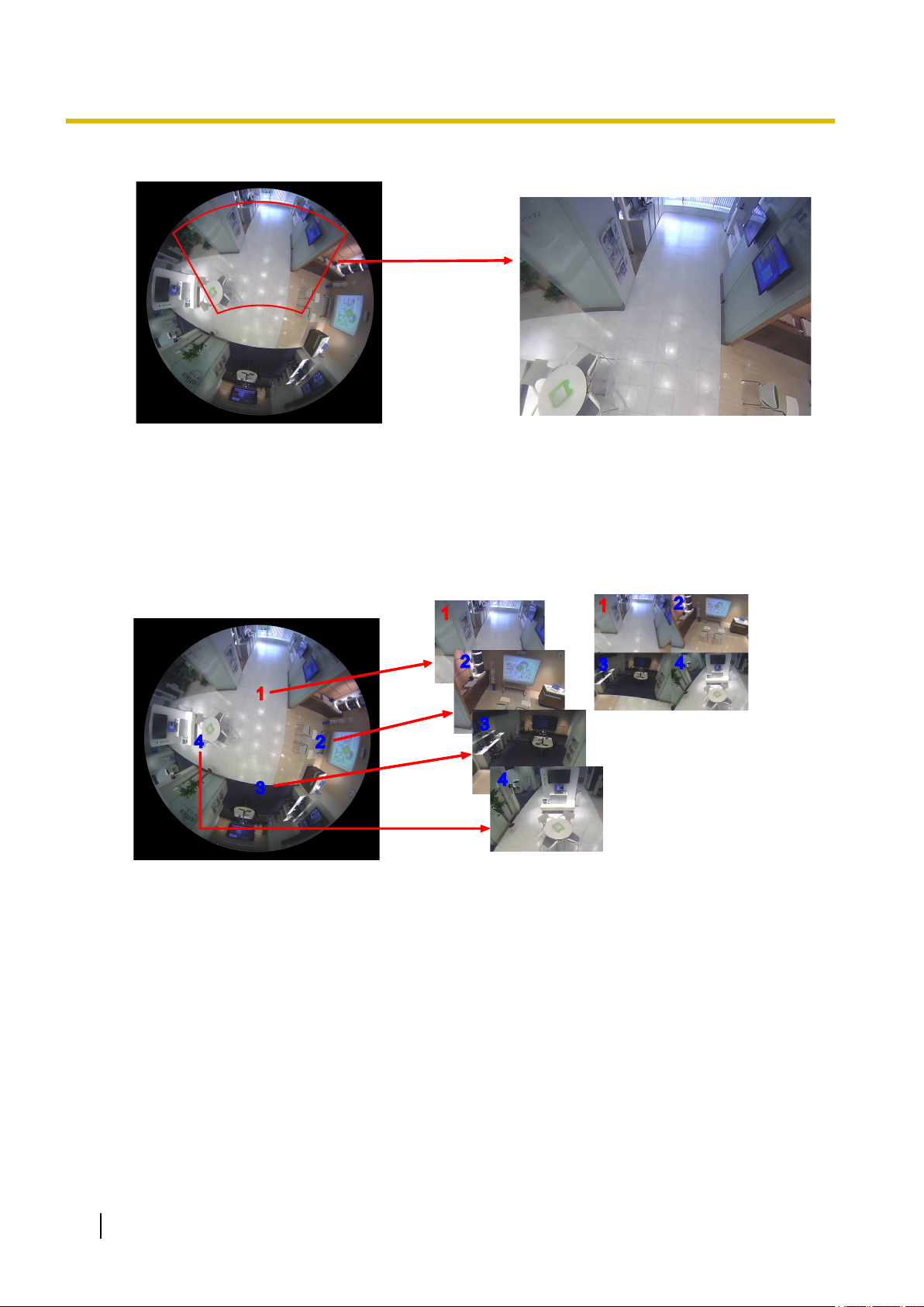
4. Single PTZ
In the Single PTZ screen, distortion in 1 fisheye image is corrected and the corrected image is displayed in a
4:3 image.
When the mouse button is used to click on an image, the clicked position of this image can be moved to the
center of the image (Click & Centering).
Operating Instructions 13
Page 14
1
3
2
4
1
2
3
4
1
2
3
4
H.264(1)
H.264(2)
1 Monitor images on a PC
The display position of images can also be changed from the fisheye control screen.
5. Quad stream
In the Quad stream, each of the four 4:3 images that had their distortions corrected are assigned a stream
number, and then displayed as H.264 images.
When H.264(2) is used, the 4 corrected images can be combined together to a single screen image and
transmitted.
14 Operating Instructions
Page 15
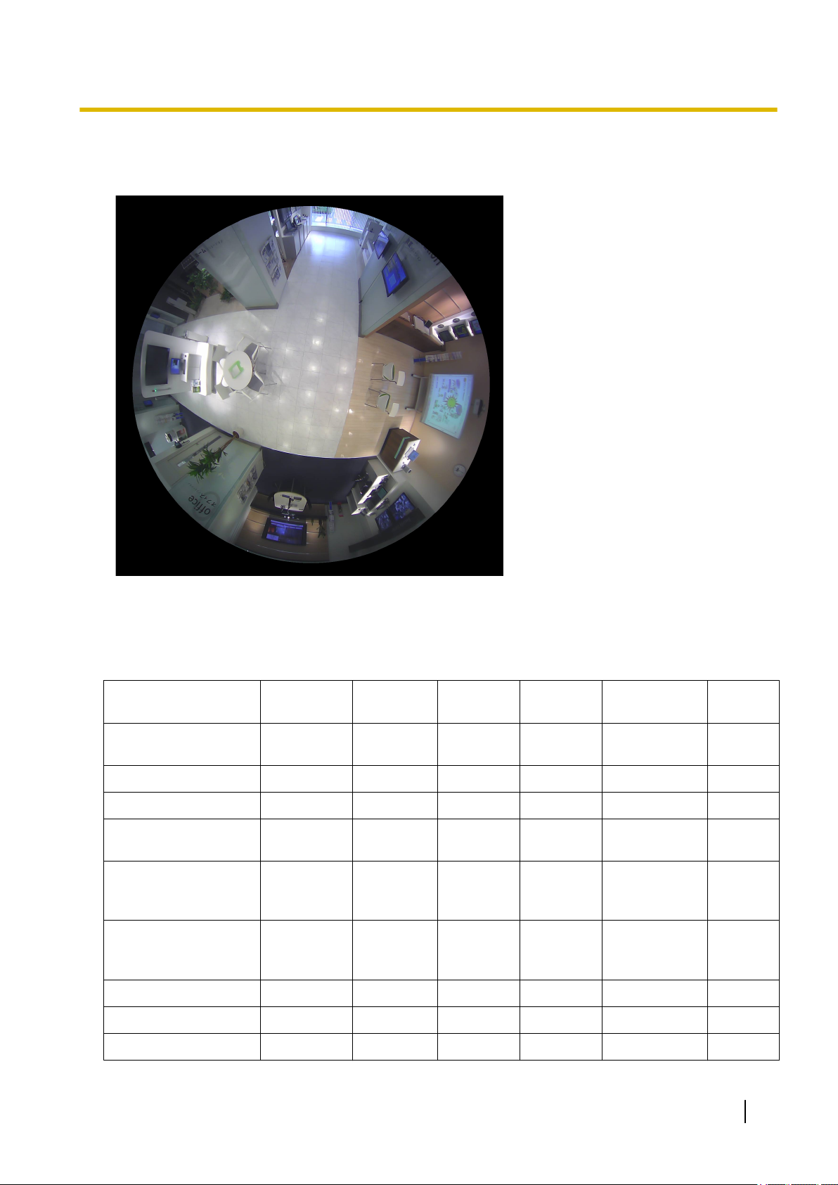
6. Fisheye
The 360° view is displayed without performing distortion correction as a fisheye image.
1 Monitor images on a PC
1.4 About image types and available functions
The following is a list of functions that can be used on the “Live” page according to the image type.
[select language]
pull-down menu
[Setup] button
[Live] button
[Compression]
buttons
[Image capture size]
buttons (when
“JPEG” is selected)
[Stream] buttons
(when “H.264” is
selected)
[Zoom] buttons
*6
[Brightness] buttons
[AUX] buttons
Double
Panorama
Panorama Quad PTZ
ü ü ü ü ü ü
ü ü ü ü ü ü
ü ü ü ü ü ü
ü ü ü ü
ü ü ü ü
*2
1, 2
ü ü
1, 2
*2
1, 2
*2
x x x
ü ü ü ü ü ü
ü ü ü ü ü ü
Single
PTZ
*2
1, 2
Quad stream Fisheye
*1
x
*1
x
1, 2, 3, 4,
Quad PTZ
ü
ü
1, 2
ü
Operating Instructions 15
Page 16

1 Monitor images on a PC
[Rec. on SD] button
[Log] button
[Multi-screen]
SD recording status
Double
Panorama
ü ü ü ü ü ü
ü ü ü ü ü ü
ü ü ü ü ü ü
ü ü ü ü ü ü
Panorama Quad PTZ
indicator
Camera title
Alarm occurrence
ü ü ü ü ü ü
ü ü ü ü ü ü
indication button
Full screen button
Snap shot button
Mic input button
Audio output button
ü ü ü ü ü ü
ü ü ü ü
ü ü ü ü ü ü
ü ü ü ü ü ü
Auto pan x x
Preset sequence x x
[Fisheye Control]
x x
button
Control Image x x
Preset x x
[Zoom] buttons
*7
x x
Control pad/buttons x x
Single
PTZ
*3
ü
ü ü
Quad stream Fisheye
ü ü ü
ü ü ü
ü
*5
ü
*5
ü
*5
ü
*4
x
ü ü
ü ü
ü ü
x
*8
ü
x
x
x
ü
x
x
x
x
ü = Available
x = Not available
*1
Because only H.264 transmission can be used, switching between H.264 and JPEG images, and changing the image capture size
setting of JPEG images is not possible.
*2
When the “Image capture mode” type is “2 Monitor”, the [Fisheye] button, [Double panorama] button, [Panorama] button, and [Quad
PTZ] button are displayed and images can be selected.
*3
Only operates on the top left image in Quad PTZ.
*4
The [Control Image] pull-down menu is displayed in gray and cannot be operated.
*5
Operations for the screen selected in the “Live” page, or the screen of the screen number selected in the [Control Image] pull-down
menu can be performed.
*6
The camera’s zoom can be operated with the [´1], [´2], and [´4] buttons on the left-hand side of the “Live” page.
*7
The camera’s zoom can be operated with the [–], [´1], and [+] buttons on the bottom of the “Live” page.
*8
Only operates in Ch1.
1.4.1 About available resolutions
An image can be displayed in any of the following resolutions depending on “Image capture mode” on the
“Live” page (except for multi-screen display).
16 Operating Instructions
Page 17

1 Monitor images on a PC
Image capture
mode
H.264(1) H.264(2) JPEG(1) JPEG(2)
9M Fisheye Fisheye:
2992x2992
1280x1280
640x640
320x320
4M Fisheye Fisheye:
2048x2048
1280x1280
640x640
320x320
Double Panorama Double
Panorama:
2560x1440
1920x1080
1280x720
640x360
320x180
Panorama Panorama:
2560x1440
1920x1080
1280x720
640x360
320x180
Fisheye:
1280x1280
640x640
320x320
Fisheye:
1280x1280
640x640
320x320
Double
Panorama:
1920x1080
1280x720
640x360
320x180
Panorama:
1920x1080
1280x720
640x360
320x180
Fisheye:
2992x2992
1280x1280
640x640
320x320
Fisheye:
2048x2048
1280x1280
640x640
320x320
Double
Panorama:
2560x1440
1920x1080
1280x720
640x360
320x180
Panorama:
2560x1440
1920x1080
1280x720
640x360
320x180
–
Fisheye:
1280x1280
640x640
320x320
Double
Panorama:
1920x1080
1280x720
640x360
320x180
Panorama:
1920x1080
1280x720
640x360
320x180
Quad PTZ Quad PTZ:
2560x1920
2048x1536
1600x1200
1280x960
800x600
VGA
QVGA
Single PTZ Single PTZ:
2560x1920
2048x1536
1600x1200
1280x960
800x600
VGA
QVGA
8M Fisheye +
Double Panorama
Fisheye:
2816x2816
1280x1280
640x640
320x320
Quad PTZ:
1280x960
800x600
VGA
QVGA
Single PTZ:
1280x960
800x600
VGA
QVGA
Double
Panorama:
1280x720
640x360
Quad PTZ:
2560x1920
2048x1536
1600x1200
1280x960
800x600
VGA
QVGA
Single PTZ:
2560x1920
2048x1536
1600x1200
1280x960
800x600
VGA
QVGA
Fisheye:
2816x2816
1280x1280
640x640
320x320
Quad PTZ:
1280x960
800x600
VGA
QVGA
Single PTZ:
1280x960
800x600
VGA
QVGA
Double
Panorama:
1280x720
640x360
Operating Instructions 17
Page 18

1 Monitor images on a PC
Image capture
mode
4M Fisheye +
Double Panorama
8M Fisheye +
Panorama
4M Fisheye +
Panorama
8M Fisheye + Quad
PTZ
H.264(1) H.264(2) JPEG(1) JPEG(2)
Fisheye:
2048x2048
1280x1280
640x640
320x320
Fisheye:
2816x2816
1280x1280
640x640
320x320
Fisheye:
2048x2048
1280x1280
640x640
320x320
Fisheye:
2816x2816
1280x1280
640x640
320x320
Double
Panorama:
1280x720
640x360
Panorama:
1280x720
640x360
Panorama:
1280x720
640x360
Quad PTZ:
1280x960
800x600
VGA
Fisheye:
2048x2048
1280x1280
640x640
320x320
Fisheye:
2816x2816
1280x1280
640x640
320x320
Fisheye:
2048x2048
1280x1280
640x640
320x320
Fisheye:
2816x2816
1280x1280
640x640
320x320
Double
Panorama:
1280x720
640x360
Panorama:
1280x720
640x360
Panorama:
1280x720
640x360
Quad PTZ:
1280x960
800x600
VGA
4M Fisheye + Quad
PTZ
Quad stream Quad stream:
Fisheye:
2048x2048
1280x1280
640x640
320x320
1280x960
800x600
VGA
QVGA
Quad PTZ:
1280x960
800x600
VGA
Quad PTZ:
2560x1920
2048x1536
1600x1200
1280x960
800x600
VGA
QVGA
Fisheye:
2048x2048
1280x1280
640x640
320x320
– –
Quad PTZ:
1280x960
800x600
VGA
IMPORTANT
• 1280x1280 cannot be selected when “9M Fisheye” is selected for “Image capture mode”, and
“On(PAL)” or “On(NTSC)” is selected for “Monitor out”.
• When “Quad stream” mode is used, 2560x1920 cannot be selected for H.264(2) if 1280x960 is selected
for H.264(1).
18 Operating Instructions
Page 19
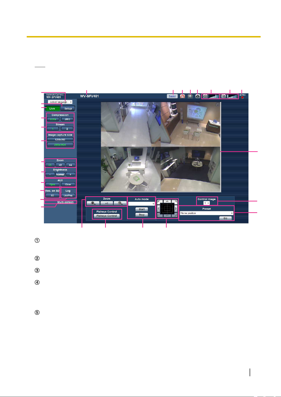
1.5 About the “Live” page
B
A
C
E
D
F
H
I
J
K
L
G
R
S
T
U
V
W
N
O
P
Q
M
X
Y
Z
a
Note
• Depending on the “Image capture mode” settings, the type of functions that can be used differ and the
displayed buttons change. Refer to page 15.
1 Monitor images on a PC
[select language] pull-down menu
The camera’s display language can be selected. The default language can be set in the [Language] in the
[Basic] settings. (®page 62)
[Setup] button
*1
Displays the setup menu. The button will turn green and the setup menu will be displayed.
[Live] button
Display the “Live” page. The button will turn green and the “Live” page will be displayed.
[Compression] buttons
• [H.264] button: The letters “H.264” on the button will turn green and an H.264 image will be displayed.
When “On” is selected for “H.264 transmission” of “H.264(1)” or “H.264(2)”, the [H.264] button will be
displayed. (®page 99)
• [JPEG] button: The letters “JPEG” on the button will turn green and JPEG image will be displayed.
[Stream] buttons
These buttons will be displayed only when an H.264 image is displayed.
• [1] button: The letter “1” will turn green and images in the main area will be displayed in accordance
with the setting of “H.264(1)”. (®page 99)
• [2] button: The letter “2” will turn green and images in the main area will be displayed in accordance
with the setting of “H.264(2)”. (®page 99)
Operating Instructions 19
Page 20

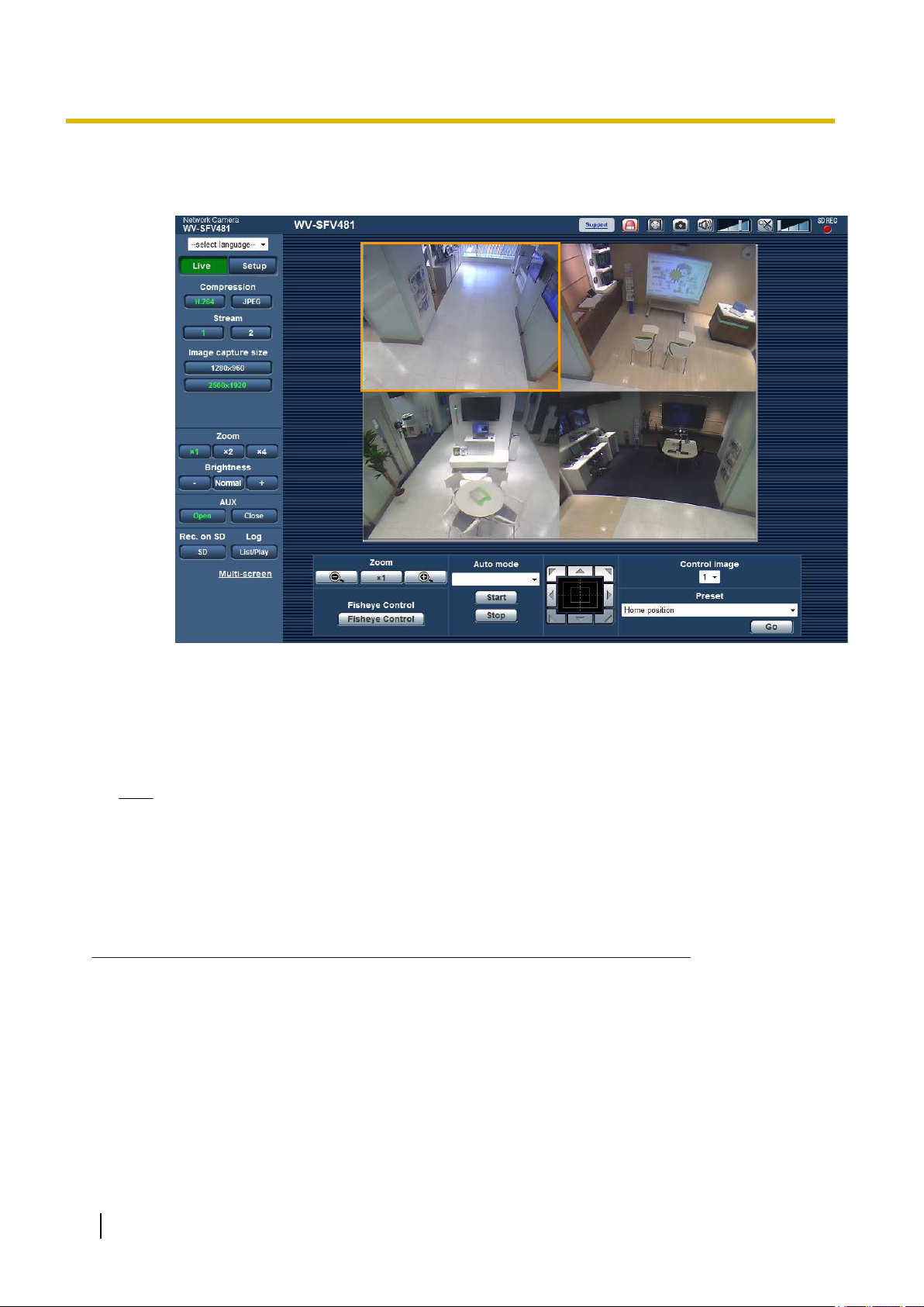
1 Monitor images on a PC
Note
• When “Quad stream” is selected for “Image capture mode”, the channel can be changed by clicking
on the buttons ([1] to [4]). The button turns green and the “Live” page of the selected channel is
displayed. The [Quad PTZ] button is displayed and images can be selected.
• When the “Image capture mode” type is “2 Monitor”, the [Fisheye], [Double panorama],
[Panorama], and [Quad PTZ] buttons are displayed and images can be selected.
[Image capture size] buttons
These buttons will be displayed only when a JPEG image is displayed.
The images that can be selected vary depending on the “Image capture mode” setting on the setup menu.
(®page 10)
Note
• Images are displayed in the image capture size selected in “JPEG(1)” or “JPEG(2)” of [JPEG] on
the [JPEG/H.264] tab.
• With the following “Image capture mode” settings, the refresh interval of JPEG images is limited to
a maximum of 15fps.
– 9M Fisheye
– Double Panorama
– Panorama
– Quad PTZ
– Single PTZ
– 4M Fisheye + Double Panorama
– 4M Fisheye + Panorama
– 4M Fisheye + Quad PTZ
• With the following “Image capture mode” settings, the refresh interval of JPEG images is limited to
a maximum of 6fps.
– 8M Fisheye + Double Panorama
– 8M Fisheye + Panorama
– 8M Fisheye + Quad PTZ
• When JPEG images and H.264 images are transmitted simultaneously, the refresh interval of JPEG
images will be limited to a maximum of 5fps.
• The image may become smaller than the actual size depending on the window size of the web
browser.
[Zoom] buttons (when the image type is Fisheye, Panorama, or Double Panorama)
Images will be zoomed in on with the electronic zoom by the viewer software “Network Camera View
4S”.
• [x1] button: The letter “x1” will turn green and images in the main area will be displayed at x1.
• [x2] button: The letter “x2” will turn green and images in the main area will be displayed at x2.
• [x4] button: The letter “x4” will turn green and images in the main area will be displayed at x4.
[Brightness] buttons
The brightness is adjustable from 0 to 255.
• (darker) button: Images become darker.
*2
• button: The adjusted brightness will return to the default brightness (64).
• (brighter) button: Images become brighter.
20 Operating Instructions
Page 21

1 Monitor images on a PC
[AUX] buttons
*2
These buttons will be displayed only when “Terminal 3” of “Alarm” is set to “AUX output” on the setup menu.
(®page 134)
• [Open] button: The letters “Open” on the button will turn green and the status of the AUX connector
will be open.
• [Close] button: The letters “Close” on the button will turn green and the status of the AUX connector
will be closed.
[Rec. on SD] button
This button will be displayed only when “Manual” is selected for “Save trigger” on the setup menu.
(®page 71)
Click this button to manually record images on the SD memory card. Refer to page 39 for descriptions
of how to manually record images on the SD memory card.
[Log] button
When the [List/Play] button is clicked, the log list will be displayed and images saved on the SD memory
card can be played.
Refer to page 45 for further information about the log list and for how to play images on the SD memory
card.
[Multi-screen]
Images from multiple cameras can be displayed on a multi-screen by registering cameras on the setup
menu. (®page 25)
[Zoom] buttons*2 (when the image type is Quad PTZ, Single PTZ, or Quad stream)
An image selected on the “Control Image” can be zoomed.
•
: Click this button to adjust the zoom ratio to the “Wide” side.
*2
• : Click this button to set the zoom ratio to x1.0.
• : Click this button to adjust the zoom ratio to the “Tele” side.
[Fisheye Control] button
When the [Fisheye Control] button is clicked, the “Fisheye Control” window will be displayed on a newly
opened window, and operations can be performed. (®page 13)
[Auto mode]
*2
Select an operation from the pull-down menu and click the [Start] button. The selected operation will start.
Click the [Stop] button to stop the operation. The selected operation will stop when the camera (panning/
tilting/zooming) is operated or when an action that is to be taken according to the settings for “Self
return” (®page 104) starts.
• Auto pan: Automatically pans.
Even when the camera is operated for zooming, the camera continues panning.
(However, panning will stop when the zoom button (x1) is clicked.) When “Quad PTZ” is selected for
“Image capture mode”, auto pan only operates for images in Ch1.
• Preset sequence: Automatically moves to the preset positions (®page 115) orderly (start from the
lowest preset position number). When “Quad PTZ” is selected for “Image capture mode”, all 4 images
are moved in the preset sequence.
Note
• If auto pan is used when the camera is mounted on a wall, depending on the tilt position, it may
appear that the range of auto pan is reduced and the camera is not panning. In this case, adjust
the tilt position up or down.
Control pad/buttons
Left-click on the control pad to adjust the horizontal/vertical position of the camera (panning/tilting).
It is also possible to pan/tilt the camera by dragging the mouse.
Zoom can be adjusted by right-clicking. When an upper/lower area of the control pad is right-clicked, the
displayed image will be zoomed in/out on. Zoom can also be adjusted using the mouse wheel.
*2
Operating Instructions 21
Page 22

1 Monitor images on a PC
[Control Image] pull-down menu
When the image type is Quad PTZ, select the screen number of the image to control its preset, zoom,
control pad/button settings.
[Preset]
*2
When a preset position is selected from the pull-down menu and the [Go] button is clicked, the image
registered for the preset position (®page 115) in advance is displayed. “H” next to the preset position
number indicates the home position. When “Home position” is selected, the camera image will move to the
home position image. When “Quad PTZ” is selected for “Image capture mode”, if preset positions “1-4”,
“5-8”, “9-12”, or “13-16” are selected, all 4 images are moved to the preset position.
When “Preset ID” is registered for a preset position, the registered preset ID will be displayed next to the
preset position number.
Preset IDs for “1-4” are displayed with the preset IDs for the lowest preset position numbers.
• The home position of each screen has been set in Preset 1 to Preset 4.
• The home position can be selected from the pull-down menu. When the home position is selected, all
4 screens will move to their home positions regardless of the “Control Image” setting.
Camera title
The camera title entered for “Camera title” on the [Basic] tab will be displayed. (®page 62)
[Support] button
When this button is clicked, the support site below will be displayed in a newly opened window. This website
contains technical information, FAQ, and other information.
http://security.panasonic.com/pss/security/support/
Alarm occurrence indication button
This button will be displayed and will blink when an alarm has occurred. When this button is clicked, the
alarm output terminal will be reset and this button will disappear. (®page 41)
Full screen button
Images will be displayed on a full screen. If the full screen button is clicked once when the image displayed
in the main area is smaller than the main area, the image is displayed corresponding to its image capture
size. If the full screen button is clicked once when images are displayed corresponding to their image
capture sizes, images are displayed in full screen. To return to the “Live” page when displaying an image
in full screen, press the [Esc] key.
Snap shot button
Click this button to take a picture (a still picture). The picture will be displayed on a newly opened window.
When right-clicking on the displayed image, the pop-up menu will be displayed. It is possible to save the
image on the PC by selecting “Save” from the displayed pop-up menu.
When “Print” is selected, printer output is enabled.
*2
Note
• For the case of using Windows 8, Windows 7 or Windows Vista, the following settings may be
required.
Open Internet Explorer, click [Tools] ® [Internet Options] ® [Security] ® [Trusted Sites] ®
[Sites]. Register the camera address on [Website] of the displayed trusted windows. After
registration, close the web browser, and then access the camera again.
• When it takes longer than the specified period to obtain the snap shot picture due to the network
environment, the snap shot picture may not be displayed.
• Snapshot cannot be used when “Quad stream” is selected for “Image capture mode”.
• Snapshot cannot be used when “On(PAL)” or “On(NTSC)” is selected for “Monitor out”.
Mic input button
Turns on/off the audio reception (hear audio from the camera on a PC). This button will be displayed only
when “Mic input”, “Interactive(Full-duplex)” or “Interactive(Half-duplex)” is selected for “Audio transmission/
reception” on the setup menu. (®page 128)
When this button is clicked, the button will turn into the
heard.
22 Operating Instructions
*3
button and audio from the camera will not be
Page 23

1 Monitor images on a PC
Audio volume can be adjusted (Low/ Middle/ High) by moving the volume cursor .
Note
• The volume cursor is not displayed when the “Audio recording” function is used.
Audio output button
Turns on/off the audio transmission (play audio from the PC on the unit speaker). This button will be
displayed only when “Audio output”, “Interactive(Full-duplex)” or “Interactive(Half-duplex)” is selected for
“Audio transmission/reception” on the setup menu. (®page 128)
The button will blink during the audio transmission.
When this button is clicked, the button will turn into the button and audio from the PC will not be heard.
Audio output volume can be adjusted (Low/Middle/High) by moving the volume cursor .
Note
*3
• When a user is using the audio transmission function with “Interactive(Half-duplex)” selected, the
receiver button and the transmission button will be inoperable for the other users. When
“Interactive(Full-duplex)” is selected, the transmission button is inoperable for other users.
• The duration of continuous audio transmission can be configured in the [Audio] tab of the setup
menu. Audio transmission stops when the specified time has passed. To turn the audio
transmission function on, click the [Audio output] button again.
• When the camera is restarted, the adjusted volume level (for both the audio transmission and
reception) will return to the level that had been set on the [Audio] tab on the setup menu.
(®page 128)
• Actual volume level will change in three steps even though the volume cursor can be adjusted
minutely.
SD recording status indicator
The status of the SD recording can be checked with this indicator.
When the SD recording starts, the SD recording status indicator will light red. It will go off when the SD
recording stops.
This indicator will be displayed when “Manual” or “Schedule” is selected for “Save trigger” on the setup
menu. (®page 70)
Main area
Images from the camera will be displayed in this area.
The current time and date will be displayed according to the settings configured for “Time display format”
and “Date/time display format”. (®page 63)
In addition, when being adjusted, the status of brightness (®page 64) will be displayed as well as the
characters configured for “Camera title on screen” (®page 64). The number of lines for the display is 2.
– When the image type is Quad PTZ or Single PTZ:
• When Quad PTZ is used, you can select the channel you want to operate by clicking in the main
area.
• Click a desired point in the main area on the “Live” page that is to be the center of the angle of
view. The camera moves to adjust the position in order to set the clicked point as the center.
• When selecting an area in the main area by dragging the mouse, the selected area will be located
at the center of the main area. In this case, the zoom ratio will be adjusted automatically.
Operating Instructions 23
Page 24
1 Monitor images on a PC
• Zoom can be adjusted using the mouse wheel.
– When the image type is Fisheye, Panorama, or Double Panorama:
• Electronic zoom can be performed with the scroll wheel.
• When clicking a desired point while displaying live images at x2 or x4 in the main area, the camera
will move to locate the clicked point at the center of the main area.
Note
• When the camera is operated by a user with a low access level, images displayed on the screen
may be changed temporarily. This does not affect operation of the camera.
• When the displayed image is being zoomed in on with a high zoom factor, the clicked point may
not always be located at the center of the main area.
• Depending on the PC in use, screen tearing* may occur when the shooting scene drastically
changes due to the GDI restrictions of the OS.
*A phenomenon in which portions of the screen are displayed out of alignment.
*1
Only operable by users whose access level is “1. Administrator”.
*2
Only operable by users whose access level is “1. Administrator” or “2. Camera control” when “On” is selected for “User
auth.” (®page 154)
*3
Operable by users who belong to the access level selected for “Permission level of audio trans./recep.” on the [Audio] tab of the
“Image/Audio” page. Refer to page 128 for the permission level of audio.
24 Operating Instructions
Page 25
C
A
B
1 Monitor images on a PC
1.6 Monitor images from multiple cameras
Images from multiple cameras can be displayed on a multi-screen. Images from 4 cameras (up to 16 cameras)
can be displayed simultaneously. To display images on a multi-screen, it is necessary to register cameras in
advance. 4 cameras can be registered as a group and up to 4 groups (16 cameras) can be registered.
(®page 132)
IMPORTANT
• When displaying images on a 16-screen, panning, tilting and zooming operations become unavailable
for images from cameras with Pan/Tilt/Zoom functions.
• When the “Image capture mode” type is “2 Monitor” or “Quad stream”, fisheye images are displayed.
(®page 95)
• When “On(NTSC)” or “On(PAL)” is selected for “Monitor out”, images are not displayed.
• When the power is turned off or the LAN cable is disconnected while displaying images, displaying
images on a multi-screen from the “Live” page will become unavailable.
Note
• When displaying images on a 4-screen, panning, tilting and zooming operations become available only
for images from cameras with Pan/Tilt/Zoom functions. Refer to our website
(http://security.panasonic.com/pss/security/support/info.html) for further information about the
compatible cameras and their versions.
• Only JPEG images can be displayed on a multi-screen. Audio will not be heard.
• When an image with the “16:9” aspect ratio is displayed on a multi-screen, it is stretched vertically to
fit the “4:3” aspect ratio. When the aspect ratio of images is “1:1”, images are stretched horizontally.
• “Network Camera Recorder with Viewer Software Lite” which supports live monitoring and recording
images from multiple cameras is available. For further information, refer to our website
(http://security.panasonic.com/pss/security/support/info.html).
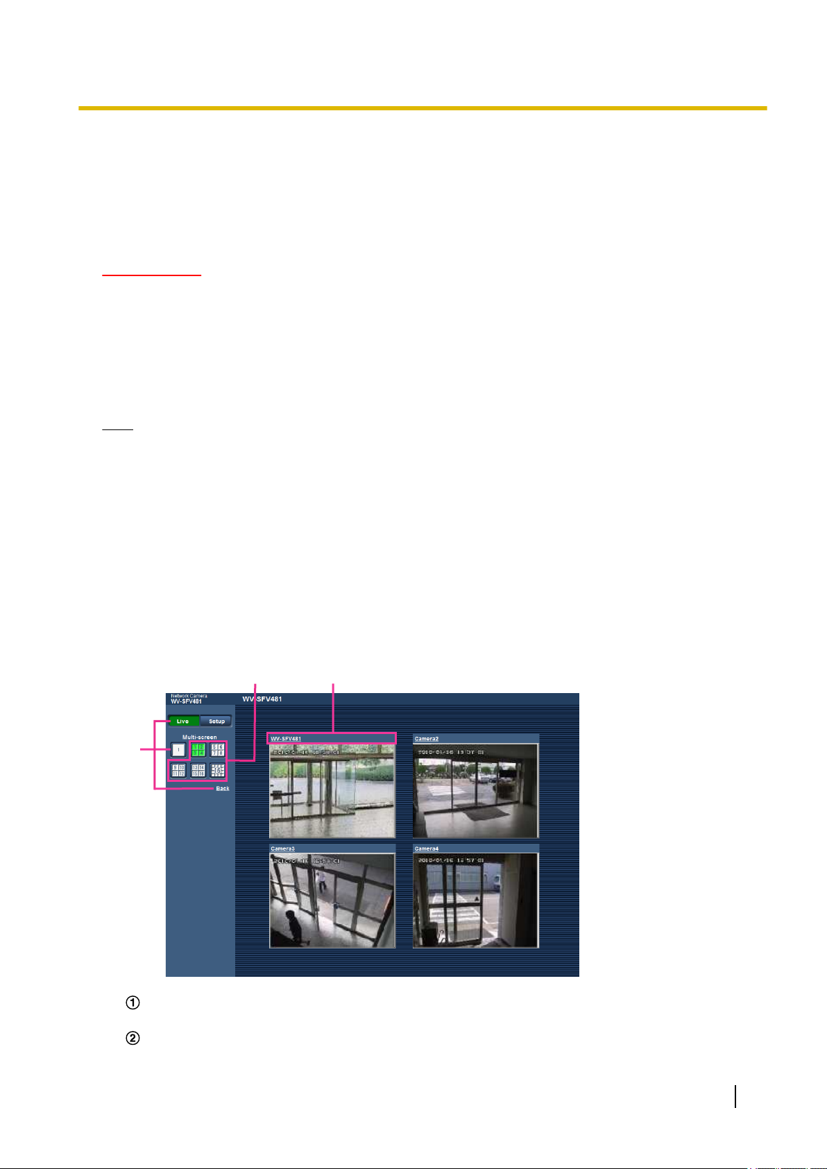
1. Click the desired [Multi-screen] on the “Live” page.
→ Images from the registered cameras will be displayed on a selected multi-screen (screen can be split
up to 16 areas). The following are instructions when displaying on a 4-split screen.
To show 1 camera screen, click the [Live] button.
You can also click “1” below “Multi-screen” or “Back” to display the camera's “Live” page.
Click the [Multi-screen] button to display images from cameras in a multi-screen of 4 to 16 screens.
Operating Instructions 25
Page 26

1 Monitor images on a PC
Click a camera title. Live images from the camera corresponding to the clicked camera title will be
displayed on the “Live” page of the newly opened window.
26 Operating Instructions
Page 27

2 Monitor images on a cellular phone/mobile terminal
2 Monitor images on a cellular phone/mobile
terminal
2.1 Monitor images on a cellular phone
It is possible to connect to the camera using a cellular phone via the Internet and monitor images (JPEG only)
from the camera on the screen of the cellular phone. You can also update the display to see the latest images.
IMPORTANT
• When the authentication window is displayed, enter the user name and password. The default user
name and password are as follows.
User name: admin
Password: 12345
To enhance the security, change the password for the user “admin”. (®page 154)
• If the cellular phone in use is not compatible with UTF-8 encode, it is impossible to display the screen
correctly.
• When “640x640”, “320x320”, “VGA”, “QVGA”, “640x360”, or “320x180” is not selected one time or more
for either one of “JPEG(1)” or “JPEG(2)” of [JPEG] on the [JPEG/H.264] tab, images cannot be viewed
from cellular phones.
Note
• It is necessary to configure the network settings of the cellular phone in advance to connect to the
Internet and monitor images from the camera. (®page 159)
• When “Auto” is selected for “Language”, the screen is displayed in English. If you want the screen to
be displayed in Japanese or Chinese, select “Japanese” or “Chinese” for “Language”. (®page 62)
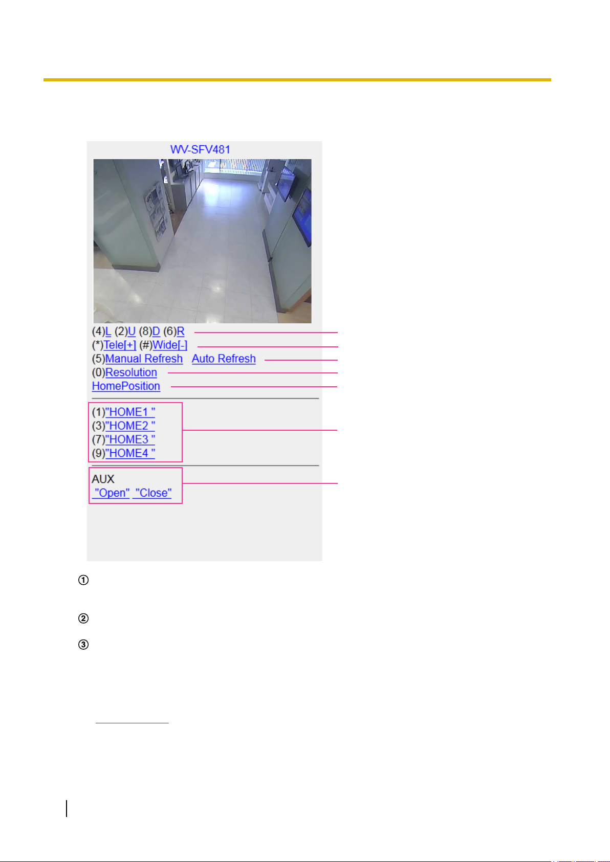
1. Access to “http://IP address/mobile”
cellular phone.
→ Images from the camera will be displayed.
• When “Quad stream” is selected for “Image capture mode”, images cannot be viewed from cellular
phones.
*1
or “http://Host name registered in the DDNS server/mobile” using a
Operating Instructions 27
Page 28
A
B
C
D
E
F
G
2 Monitor images on a cellular phone/mobile terminal
• When the “Image capture mode” type is “2 Monitor”, the types of images configured in the “Image
capture size” of “"Live" page (Initial display)” are displayed. (®page 95)
Pan/tilt*2
The display position of camera images can be controlled by panning and tilting. The camera will pan
or tilt to each direction by pressing the corresponding dial key.
Zoom display*2
It is possible to perform zooming operations of the camera by pressing “*” or “#”.
Refresh control
Press the dial key “5” or the [Manual Refresh] button to refresh the camera images.
Press the [Auto Refresh] button to refresh the images from the camera in 5-second intervals.
When the dial key “5” or the [Manual Refresh] button is pressed again, the refresh mode of the camera
will return to manual refresh.
*3
IMPORTANT
• Transmission will be periodically performed when “Auto Refresh” is selected for the camera
image. Confirm the contract plan of the cellular phone in use before using this function.
• Depending on the cellular phone in use, “Auto Refresh” may be unavailable.
28 Operating Instructions
*3
Page 29

2 Monitor images on a cellular phone/mobile terminal
Resolution control
Changes the image capture size by pressing the dial key “0”.
• Changes the image capture size between 320x320 (320x240 or 320x180) (default) and 640x640
(640x480 or 640x360).
Home position*2
The image from the camera can be moved to the home position.
Preset*2
*3
The camera will move to the designated preset position to display images by pressing the dial key
corresponding to the desired channel. (The dial key numbers are not displayed for Preset No 5 or
greater. Only preset IDs will be displayed for them.) (®page 115)
Note
*3
• A maximum of 8 designated presets can be operated.
AUX control
Controls the AUX terminal.
These buttons will be displayed only when “AUX output” is selected for “Terminal 3” on the setup menu.
(®page 134)
Note
*2
• Some cellular phones cannot change the image capture size even when resolution is changed by
resolution control.
• Depending on the image capture size selected for “JPEG(1)” or “JPEG(2)”, “Resolution” may not be
able to be used.
• When the HTTP port number is changed from “80”, enter “http://IP address: (colon) + port number/
mobile”*1 in the address box of the browser. When using the DDNS function, access to “http://Host
name registered in the DDNS server: (colon) + port number/mobile”.
• When “HTTPS” is selected for “HTTPS” - “Connection” on the [Advanced] tab of the “Network” page,
enter as follows.
“https://IP address: (colon) + port number/mobile” or “https://Host name registered in the DDNS server:
(colon) + port number/mobile”
• When the authentication window is displayed, enter the user name of an administrator or user and
password. Depending on the cellular phone in use, password entry may be required each time the
screen is switched.
• It is impossible to transmit/receive audio using a cellular phone.
• Depending on the cellular phone in use, larger size images may not be displayed. In this case, selecting
“9 Low” for “Image quality setting” of “JPEG” (®page 95) may sometimes solve this problem.
• Depending on the cellular phone in use or its contract plan, it may be impossible to access.
*1
IP address is the global WAN IP address of the router that can be accessed via the Internet.
*2
When “User auth.” is set to “On” (®page 154), only users with the access level of “1. Administrator” or “2. Camera control” will be
displayed.
*3
Unavailable when the image type is Panorama, Double Panorama, Fisheye or Quad stream. When the image type is Quad PTZ,
operations are only possible for the top left image.
2.2 Monitor images on a mobile terminal
It is possible to connect to the camera using a mobile terminal via the Internet and monitor images (MJPEG
or JPEG) from the camera on the screen of the mobile terminal. It is also possible to refresh images to display
the latest image.
The compatible mobile terminals are shown as follows. (As of October, 2014)
– iPad, iPhone, iPod touch (iOS 4.2.1 or later)
– Android™ mobile terminals
Operating Instructions 29
Page 30

2 Monitor images on a cellular phone/mobile terminal
When an Android terminal is used, an MJPEG format image is displayed by the Firefox® browser, but a JPEG
format image is displayed by the standard browser.
For further information about compatible devices, refer to our website
(http://security.panasonic.com/pss/security/support/info.html).
IMPORTANT
• When the authentication window is displayed, enter the user name and password. The default user
name and password are as follows.
User name: admin
Password: 12345
To enhance the security, change the password for the user “admin”. (®page 154)
• An image can be displayed in any of the following image capture sizes depending on “Image capture
mode”.
Image capture mode
9M Fisheye 1280x1280/640x640/320x320
4M Fisheye 2048x2048/1280x1280/640x640/320x320
Double Panorama 1920x1080/1280x720/640x360/320x180
Panorama 1920x1080/1280x720/640x360/320x180
Quad PTZ 2048x1536/1600x1200/1280x960/800x600/VGA/QVGA
Single PTZ 2048x1536/1600x1200/1280x960/800x600/VGA/QVGA
8M Fisheye + Double
Panorama
4M Fisheye + Double
Panorama
8M Fisheye + Panorama Fisheye:
Fisheye:
1280x1280/640x640/320x320
Double Panorama:
1280x720/640x360
Fisheye:
2048x2048/1280x1280/640x640/320x320
Double Panorama:
1280x720/640x360
1280x1280/640x640/320x320
Panorama:
1280x720/640x360
Image capture size
4M Fisheye + Panorama Fisheye:
2048x2048/1280x1280/640x640/320x320
Panorama:
1280x720/640x360
8M Fisheye + Quad PTZ Fisheye:
1280x1280/640x640/320x320
Quad PTZ:
1280x960/800x600/VGA
4M Fisheye + Quad PTZ Fisheye:
2048x2048/1280x1280/640x640/320x320
Quad PTZ:
1280x960/800x600/VGA
Quad stream –
30 Operating Instructions
Page 31

A
B
C
D
2 Monitor images on a cellular phone/mobile terminal
Note
• It is necessary to configure the network settings of the mobile terminal in advance to connect to the
Internet and monitor images from the camera. (®page 159)
1. Access to “http://IP address/cam”
*1
or “http://Host name registered in the DDNS server/cam” using a mobile
terminal.
→ Images from the camera will be displayed.
Note
• When “Quad stream” is selected for “Image capture mode”, images cannot be displayed.
• When the “Image capture mode” type is “2 Monitor”, the types of images configured in the “Image
capture size” of “"Live" page (Initial display)” are displayed.
Live images area
Displays images from the camera.
Operation buttons area
When functions are selected in the function selection area D, buttons to operate those functions are
displayed.
Zoom operation area
When the image type is Quad PTZ or Single PTZ, buttons to operate the zoom are displayed.
Function selection area
When functions that can be operated are selected, operation buttons are displayed in the operation
buttons area B.
Operating Instructions 31
Page 32

C
D
A
B
E
2 Monitor images on a cellular phone/mobile terminal
2. Click the button of the function that you want to operate.
Pan/tilt
Preset
*3
*3
Resolution control
AUX control
Zoom display
*3
Each function is explained below.
32 Operating Instructions
Page 33

2 Monitor images on a cellular phone/mobile terminal
Pan/Tilt
Press the
*3
button to display the buttons used to operate pan/tilt on the screen. The pan/tilt can be
adjusted in each direction with the , , , and buttons.
*3
Preset
Press the
button to display the buttons used to select the preset position on the screen. Camera
images are displayed of the registered preset directions according to the preset numbers selected from
the buttons.
Operating Instructions 33
Page 34

2 Monitor images on a cellular phone/mobile terminal
Note
• Only preset numbers 1 to 4 can be used for preset operations.
Resolution control
Press the
button to display the buttons used to select the resolution on the screen.
The resolution can be changed by selecting a resolution setting from the buttons.
Images are displayed in the image capture size selected in “JPEG(1)” or “JPEG(2)” of [JPEG] on the
[JPEG/H.264] tab.
34 Operating Instructions
Page 35

2 Monitor images on a cellular phone/mobile terminal
AUX control
Press the button to display the buttons used to operate the AUX output on the screen. The AUX
output terminals can be controlled with the and buttons.
This function is only displayed when [Terminal 3] is set to [AUX output] on the settings menu.
(®page 134)
Operating Instructions 35
Page 36

2 Monitor images on a cellular phone/mobile terminal
36 Operating Instructions
Page 37

2 Monitor images on a cellular phone/mobile terminal
Zoom display
The camera’s zoom can be operated with the , , and buttons.
*3
Note
• You can change the image size displayed on the mobile terminal by accessing the following addresses.
– Large display: http://IP address/cam/dl
– Medium display: http://IP address/cam/dm
– Small display: http://IP address/cam/ds
• When the resolution is changed by the resolution control, the displayed resolution changes but the
image size remains the same.
• When the HTTP port number is changed from “80”, enter “http://IP address: (colon) + port number/
cam”*1 in the address box of the browser. When using the DDNS function, access to “http://Host name
registered in the DDNS server: (colon) + port number/cam”*2.
• When “HTTPS” is selected for “HTTPS” - “Connection” on the [Advanced] tab of the “Network” page,
enter as follows.
“https://IP address: (colon) + port number/cam” or “https://Host name registered in the DDNS server:
(colon) + port number/cam”
• When the authentication window is displayed, enter the user name of an administrator or user and
password. Depending on the mobile terminal in use, password entry may be required each time the
screen is switched.
• It is impossible to transmit/receive audio using a mobile terminal.
Operating Instructions 37
Page 38

2 Monitor images on a cellular phone/mobile terminal
• Depending on the mobile terminal in use, larger size images may not be displayed. In this case,
selecting “9 Low” for “Image quality setting” of “JPEG” (®page 95) may sometimes solve this
problem.
• Depending on the mobile terminal in use or its contract plan, it may be impossible to access.
*1
IP address is the global WAN IP address of the router that can be accessed via the Internet. However, when accessing the same
LAN as the camera with a wireless compatible mobile terminal, the IP address is the local IP address.
*2
Only when accessing the camera via the Internet.
*3
Unavailable when the image type is Panorama, Double Panorama, Fisheye or Quad stream. When the image type is Quad PTZ,
operations are only possible for the top left image.
38 Operating Instructions
Page 39

3 Record images on the SD memory card manually
3 Record images on the SD memory card
manually
Images displayed on the “Live” page can be recorded on the SD memory card manually. This button is operable
only when “Manual” is selected for “Save trigger” on the [SD memory card] tab on the “Basic” page of the setup
menu. (®page 71)
It is possible to select “JPEG(1)”, “JPEG(2)”, “H.264(1)”, or “H.264(2)” on “Recording format” of the setup menu
(®page 71). When “JPEG(1)” or “JPEG(2)” is selected for “Recording format”, still image data are recorded.
When “H.264(1)” or “H.264(2)” is selected, video data are recorded.
Images recorded on the SD memory card can be copied onto the PC. (®page 76)
1. Display the “Live” page. (®page 7)
2. Click the [SD] button.
→ The SD recording window will open.
3. Click the [Start] button to start recording images on the SD memory card. The SD recording status indicator
will light red (®page 19) while images are being recorded on the SD memory card.
The image saving interval can be configured on the [SD memory card] tab of the “Basic” page.
(®page 71)
4. Click the [Stop] button to stop saving images on the SD memory card.
® The SD recording status indicator will turn off.
5. Click the [Close] button to close the window.
Operating Instructions 39
Page 40

3 Record images on the SD memory card manually
Note
• Image data saved on Drive B can be obtained by executing “Access img.” on the [SD memory card]
tab and logging in from the user authentication window (®page 76).
The destination to save image data is a fixed directory on Drive B. (®page 231)
• When the [Start] button is clicked immediately after the [Stop] button is clicked, saving of images may
not start. In this case, click the [Start] button again.
40 Operating Instructions
Page 41

4 Action at an alarm occurrence
4 Action at an alarm occurrence
The alarm action (camera action at an alarm occurrence) will be performed when the following alarms occur.
4.1 Alarm type
• Terminal alarm: When connecting an alarm device such as a sensor to the alarm input terminal of the
camera, the alarm action will be performed when the connected alarm device is activated.
• VMD alarm: When motion is detected in the set VMD area, the alarm action will be performed.
*VMD stands for “Video Motion Detection”.
• Command alarm: When a Panasonic alarm protocol is received from the connected device via a network,
the alarm action will be performed.
4.2 Action at an alarm occurrence
Display the alarm occurrence indication button on the “Live” page
The alarm occurrence indication button will be displayed on the “Live” page at an alarm occurrence.
(®page 19)
IMPORTANT
• When “Polling(30s)” is selected for “Alarm status update mode” (®page 62), the Alarm occurrence
indication button will be refreshed in 30-second intervals. For this reason, it may take a maximum of
30 seconds until the alarm occurrence indication button is displayed on the “Live” page at an alarm
occurrence.
Notify of alarm occurrences to the device connected to the alarm connector
It is possible to output signals from the alarm output terminal of the camera and sound the buzzer when an
alarm occurs. The settings for the alarm output can be configured in the “Alarm output terminal setup” section
of the [Alarm] tab of the “Alarm” page. (®page 134, page 136)
Save images on the SD memory card
When an alarm occurs, images (JPEG/H.264) will be saved on the SD memory card. The settings to save
images on the SD memory card can be configured on the [SD memory card] tab (®page 70) of the “Basic”
page and the [Alarm] tab of the “Alarm” page. (®page 137)
Transmit an image onto a server automatically
An alarm image can be transmitted at an alarm occurrence to the server designated in advance. The settings
required to transmit an alarm image to a server can be configured in the “Alarm image” section on the
[Alarm] tab of the “Alarm” page (®page 137) and the [Advanced] tab of the “Network” page (®page 166).
IMPORTANT
• When “Quad stream” is selected for “Image capture mode”, images cannot be transmitted to an FTP
server.
Operating Instructions 41
Page 42

4 Action at an alarm occurrence
Notify of alarm occurrences by E-mail
Alarm E-mail (alarm occurrence notification) can be sent at an alarm occurrence to the E-mail addresses
registered in advance. Up to 4 addresses can be registered as recipients of the alarm E-mail. An alarm image
(still picture) can be sent with the alarm E-mail as an attached file. The settings for alarm E-mail can be
configured in the “E-mail notification” section on the [Alarm] tab of the “Alarm” page (®page 137) and the
[Advanced] tab of the “Network” page (®page 164).
IMPORTANT
• When “Quad stream” is selected for “Image capture mode”, alarm E-mails cannot be sent with still
picture attachments.
Notify of alarm occurrences to the designated addresses (Panasonic alarm
protocol notification)
This function is available only when a Panasonic device, such as the network disk recorder, is connected to
the system. When “On” is selected for “Panasonic alarm protocol notification”, the connected Panasonic device
will be notified that the camera is in the alarm state. The settings for Panasonic alarm protocol can be configured
in the Panasonic alarm protocol section of the [Notification] tab of the “Alarm” page. (®page 150)
Notify of alarm occurrences to the designated HTTP server (HTTP alarm
notification)
Alarm occurrence notifications can be sent at an alarm occurrence to the HTTP servers registered in advance.
Up to 5 HTTP servers can be registered as recipients of alarm notifications. The URL sent to HTTP servers
with alarm notifications can be specified. The settings for HTTP alarm notification can be configured on the
[Notification] tab of the “Alarm” page. (®page 152)
42 Operating Instructions
Page 43

5 Transmit images onto an FTP server
5 Transmit images onto an FTP server
Images can be transmitted to an FTP server. By configuring the following settings, transmission of images
captured at an alarm occurrence or captured at a designated interval to an FTP server will become available.
IMPORTANT
• When using this function, set the user name and the password to access the FTP server to restrict
users who can log into the FTP server.
• When “Quad stream” is selected for “Image capture mode”, images cannot be transmitted to an FTP
server.
• When “On(NTSC)” or “On(PAL)” is selected for “Monitor out”, image transmission to the FTP server is
unavailable.
5.1 Transmit an alarm image at an alarm occurrence (Alarm image transmission)
An alarm image can be transmitted at an alarm occurrence to the FTP server. To transmit alarm images to an
FTP server, it is necessary to configure the settings in advance.
FTP server settings and settings relating to alarm image transmission can be configured in the “FTP” section
of the [Advanced] tab of the “Network” page. (®page 166) Settings can also be configured from the “Alarm
image FTP transmission” settings of “Camera action on alarm” on the [Alarm] tab of the “Alarm” page.
(®page 137)
Note
• Depending on the network traffic, the number of the transmitted images may not reach the set number
of images to be transmitted.
• Alarm images failed to be transmitted to the FTP server at an alarm occurrence will not be saved on
the SD memory card. However, images that fail to be transmitted with the FTP periodic image
transmission will be saved.
When “On” is selected for both the alarm image transmission function and the FTP periodic image
transmission function, the alarm image transmission function will be given priority over the FTP periodic
image transmission function. Also, when “On” is selected for the “FTP transmission retry” FTP setting
(®page 168), alarm images will be retransmitted if there is an FTP transmission failure. Therefore, if
there is continuous retransmission due to network problems or other factors, periodic transmission will
not be performed and images that fail to be transmitted with the FTP periodic image transmission will
not be saved to an SD memory card.
5.2 Transmit images at a designated interval or period (FTP periodic image transmission)
Images can be transmitted at a designated interval or period. To transmit images at a designated interval or
period, it is necessary to configure the settings in advance.
FTP server settings and settings relating to FTP periodic transmission image transmission can be configured
in the “FTP” section of the [Advanced] tab of the “Network” page. (®page 166)
Configure the schedule settings of the FTP periodic image transmission on the “Schedule” page.
Note
• Depending on the line speed or the traffic, images may not be transmitted at the designated interval.
Operating Instructions 43
Page 44

5 Transmit images onto an FTP server
• When “On” is selected for both the alarm image transmission function and the FTP periodic image
transmission function, the alarm image transmission function will be given priority over the FTP periodic
image transmission function. Therefore, images may not be transmitted at the interval designated on
the “FTP periodic image transmission” setting.
5.3 Save images on the SD memory card when images fail to transmit using the FTP periodic image transmission function
Images that have failed to transmit using the FTP periodic image transmission can be saved automatically on
the SD memory card. It is possible to select a trigger to save images on the SD memory card on the [SD
memory card] tab of the “Basic” page. (®page 70)
To use the SD memory recording function featured in Panasonic network disk recorder, select “Off” for “FTP
periodic image transmission” (®page 169) and “FTP error” for “Save trigger” of “Recording
stream” (®page 71).
Note
• When “On” is selected for both the alarm image transmission function and the FTP periodic image
transmission function, the alarm image transmission function will be given priority over the FTP periodic
image transmission function. Also, when “On” is selected for the “FTP transmission retry” FTP setting
(®page 168), alarm images will be retransmitted if there is an FTP transmission failure. Therefore, if
there is continuous retransmission due to network problems or other factors, periodic transmission will
not be performed and images that fail to be transmitted with the FTP periodic image transmission will
not be saved to an SD memory card.
IMPORTANT
• We make no guarantee for any damages of files on the SD memory card incurred by malfunction or
error occurrence in files saved in the SD memory card regardless of what the cause may be.
44 Operating Instructions
Page 45

6 Display the log list
6 Display the log list
The history of various logs will be displayed in list form.
• Alarm log: Logs of the alarm occurrences such as time and date of the alarm occurrences, the image
recording period and the alarm type will be displayed.
• Manual/Schedule log: Logs filed when images have been recorded manually or during the period of the
schedule, and the image recording period will be displayed.
• FTP trans. error log: Logs filed when the FTP periodic image transmission function has failed will be
displayed.
1. Display the “Live” page.
Operating Instructions 45
Page 46

A
C
E
D
B
6 Display the log list
2. Click the [List/Play] button.
→ The log list will be displayed in a newly opened window (log list window).
IMPORTANT
• Only a single user can operate the log list window. Other users cannot access the log list window.
Time
Displays the time period of the data recorded on the SD memory card.
Event
Select a log type to display on the log list.
• All: All logs will be displayed.
• Select: Only the logs of the selected log type will be displayed.
– Alarm log: The log when an alarm is detected will be displayed.
– Manual/Schedule log: Manual and Schedule logs will be displayed.
– FTP trans. error log: Logs filed when the FTP periodic image transmission function has failed will
be displayed.
• Default: All
Recording time
Configure the time period of logs displayed on the log list.
• From: Configure the starting period of logs displayed on the log list.
– First recording: Displays from the first log recorded on the SD memory card.
– Today: Displays the logs recorded today.
46 Operating Instructions
Page 47

6 Display the log list
– Yesterday: Displays the logs recorded from yesterday to the present day.
– Last 7 days: Displays the logs recorded from 6 days ago to the present day.
– Last 30 days: Displays the logs recorded from 29 days ago to the present day.
– Date/time: Displays the logs recorded from the entered date and time on “Date/time” box.
• To: Configure the ending period of logs displayed on the log list when “First recording” or “Date/time”
is selected for “From”.
– Last recording: Displays until the last log recorded on the SD memory card.
– Date/time: Displays the logs recorded until the entered date and time on “Date/time” box.
[Search] button
Searches for logs according to the conditions specified in “Event” and “Recording time”.
The search result will be displayed on the log list.
Log list
Displays the log search results.
You can play back recorded data by clicking on the time or duration of the recorded data displayed under
[Time] and [Duration].
• [Top] button: Click this button to display the log listed at the top.
• [Prev. page] button: Click this button to display the previous page of the log list.
• [Next page] button: Click this button to display the next page of the log list.
• [Last] button: Click this button to display the log listed at the bottom.
• [Time & date]: Time and date when each log has been recorded will be displayed.
Note
• When “Off” is selected for “Time display format”, the alarm occurrence times are displayed in
24 hour time format.
• The recording timing of logs is as follows.
– Alarm log: Alarm occurrence time and date will be filed as a log.
– Manual/Schedule log: Time and date when recording of images onto the SD memory card
started manually or during the period of the schedule will be filed as a log. When images
are recorded sequentially, if “JPEG” is selected for “Recording format”, logs will be filed on
the hour every hour (12:00, 1:00, 2:00, etc.). If “H.264” is selected for “Recording format”,
logs will be filed every hour from the time when recording starts. However, depending on
the photographic subject and the setting used, logs may be filed in periods of over an hour.
– FTP trans. error log: Logs will be filed every one hour.
• [Duration]: Displays the period of time that the data has been recorded on the SD memory card.
Note
• The difference between the recording end time and recording start time of the image is
calculated by rounding off to the nearest tenth of a second. For this reason, when only 1 JPEG
image is saved, 00:00:00 is displayed for the duration.
• [Event]: The event type will be displayed.
– MN/SC: Log by “Manual/Schedule”
– TRM1: Alarm by alarm input to Terminal 1
– TRM2: Alarm by alarm input to Terminal 2
– TRM3: Alarm by alarm input to Terminal 3
– VMD: Alarm by VMD alarm
– COM: Alarm by command alarm
– FTP: Logs saved from FTP periodic image transmission errors
• [SD memory card]: Available capacity and the original capacity of the SD memory card will be
displayed.
• [Delete] button: Click this button to delete the currently displayed log list. When using the SD memory
card, images associated with the log list will also be deleted.
Operating Instructions 47
Page 48

6 Display the log list
IMPORTANT
• If there are too many recorded data files, it may take time to delete all of them. (When the total
• In the process of the deletion, “Alarm” and “Manual/Schedule” cannot be operated.
• Do not turn off the power of the camera until the deletion is complete. When the power of the
• [Download] button: Click this button to download all logs of the selected log list onto the PC.
Note
• The following settings may be required.
• Up to 50,000 logs can be downloaded. When more than 50,000 logs are filed, the older logs
• [Close] button: Click this button to close the log list window.
size is 1 GB, it may require about 1 hour.) Formatting the SD memory card can shorten the
time to delete all the data.
camera is turned off in the process of the deletion, some images may remain on the SD memory
card. In this case, click the [Delete] button on the same log list window used to delete the logs.
Open Internet Explorer, click [Tools] ® [Internet Options] ® [Security] ® [Trusted Sites] ®
[Sites]. Register the camera address on [Website] of the displayed trusted windows.
After registration, close the web browser, and then access the camera again.
will be overwritten by the newer logs. In this case, the oldest log is the first to be overwritten.
48 Operating Instructions
Page 49

A
7 Playback of images on the SD memory card
7 Playback of images on the SD memory card
When clicking a time and date listed on the log list window, the “Live” page will turn to the “Playback” page.
When images associated with the clicked time and date are on the SD memory card, the first image of them
will be displayed.
The display format varies depending on the “Recording format” of the SD memory card.
IMPORTANT
• Refresh interval of images may become slow during playback or download.
• When many images are saved on the SD memory card, it may take time to display images on the
“Playback” page.
• Regardless of the size of the images saved on the SD memory card, the images will be displayed in
the fixed size for each “Image capture mode” on the “Playback” page.
– When 9M Fisheye/4M Fisheye is selected for “Image capture mode”: 480x480 size
– When Quad PTZ/Single PTZ/8M Fisheye + Quad PTZ/4M Fisheye + Quad PTZ/Quad stream is
selected for Image capture mode: VGA size
– When Double Panorama/Panorama/8M Fisheye + Double Panorama/4M Fisheye + Double
Panorama/8M Fisheye + Panorama/4M Fisheye + Panorama is selected for “Image capture
mode”: 640x360 size
Therefore, images may look coarse on the “Playback” page.
• When playing images by selecting an FTP error log on the log list, images may not be played in order
of images recorded on the SD memory card if they have been recorded on the SD memory card with
selected value for the “Transmission interval” setting of “FTP periodic image transmission” on the
[Advanced] tab is “1min” or less.
• The playback refresh interval may become slower when recording data to the SD memory card.
7.1 Playback “JPEG(1)”/“JPEG(2)” images saved to the SD memory card
Number of images
When clicking a time and date listed on the log list window, total number of images associated with the
clicked time and date, and the number of the currently displayed image will be displayed.
Operating Instructions 49
Page 50

7 Playback of images on the SD memory card
Note
• Enter the desired number of image and press the [Enter] key on the keyboard. The image of the
designated number will be displayed.
[REW] button
Each time the button is clicked, the playback speed will change.
When the [PLAY] button or the [REV PLAY] button is clicked during fast reverse playback, playback speed will
return to the normal playback speed.
[REV PLAY] button
Images will be played in reverse sequential order.
[PLAY] button
When this button is clicked, images will be played in sequential order.
[FF] button
Each time the button is clicked, the playback speed will change.
When the [PLAY] button or the [REV PLAY] button is clicked during fast playback/fast reverse playback,
playback speed will return to the normal playback speed.
[TOP] button
The first image will be displayed.
[PREV. IMAGE] button
The previous frame will be displayed and paused when this button is clicked during playback.
Each time this button is clicked during pausing, the frame previous to the currently displayed frame will be
displayed.
Note
• When the mouse button is held down while the mouse pointer is on this button, the image number will
be decreased.
When the mouse button is released, the decreasing of the image number will stop and the image
corresponding to the currently displayed number will be displayed.
[PAUSE] button
Playback will be paused when this button is clicked during playback.
Playback will resume when this button is clicked during pausing.
[STOP] button
Playback will stop and the “Playback” window will turn to the “Live” page.
[NEXT IMAGE] button
The next frame will be displayed and paused when this button is clicked during playback.
Each time this button is clicked during pausing, the frame next to the currently displayed frame will be displayed.
Note
• When the mouse button is held down while the mouse pointer is on this button, the image number will
be increased.
When the mouse button is released, the increment of the image number will stop and the image number
displayed at the moment when the mouse button is released will be displayed.
[LAST] button
The last image will be displayed.
50 Operating Instructions
Page 51

7 Playback of images on the SD memory card
Browse
[Start] button
The selected image will be downloaded onto the PC. Before downloading images, designate the destination
directory in advance. (®page 92)
The following window will be displayed when the [Start] button is clicked.
Select the image to be downloaded, and then click the [OK] button.
• All: All images saved at the selected time and date will be downloaded.
• Current image: Only the currently displayed image will be downloaded.
• Download range: Images in the specified range will be downloaded.
Note
• When the [Cancel] button is clicked in the process of the download, the download will be canceled. In
this case, images already downloaded before clicking the [Cancel] button will be saved on the PC.
[Browse] button
When successfully logged in after the user authentication process, a folder on the SD memory card in which
images are saved will be displayed. (®page 76)
Operating Instructions 51
Page 52

A
7 Playback of images on the SD memory card
7.2 Playback “H.264(1)”/“H.264(2)” images saved to the SD memory card
IMPORTANT
• Depending on the network environment, download of video data may fail.
Slider bar
By operating the slider bar, you can select where to start playing images from. The slider bar can only be
used before playing images, or when playing is paused or stopped.
[PAUSE] button
Playback will be paused when this button is clicked during playback.
[PLAY] button
When this button is clicked, recorded data will be played.
Note
• If audio is recorded, it can be played back, but the image and audio will not be synchronized. Therefore,
images and audio may not always match. When data is being recorded to the SD memory card, audio
may sound as if it is cutting out and the audio quality may be reduced.
• When recorded audio is played back, the refresh interval of live images and playback may become
slow.
• Recorded audio is not played back when “Off” or “Interactive(Half-duplex)” is selected for “Audio
mode” on the [Audio] tab of the “Image/Audio” page.
• Audio is only played for users who belong to the access level selected for “Permission level of audio
trans./recep.” on the [Audio] tab of the “Image/Audio” page.
[FF] button
Each time this button is clicked, the playback speed will change. When the [PLAY] button is clicked during fast
playback, playback speed will return to the normal playback speed.
52 Operating Instructions
Page 53

7 Playback of images on the SD memory card
Note
• The maximum speed of the fast playback varies depending on the setting of “Max bit rate” - “H.264
recording” of the SD memory card. If any of the following also applies to “Transmission priority” or “Max
bit rate (per client)” on the [JPEG/H.264] tab of the “Image/Audio” page, playback speed becomes
constant (x1), not fast playback.
– When “Frame rate” or “Advanced VBR” is selected for “Transmission priority”, and “14436kbps” or
a higher value is selected for the maximum value of “Max bit rate (per client)”
– When “Constant bit rate” is selected for “Transmission priority”, and “16384kbps” is selected for
the maximum value of “Max bit rate (per client)”
• Recorded audio will not be played back during fast playback.
[5s backward] button
Each time this button is clicked, the recorded data goes back by 5 seconds and starts playing.
[5s forward] button
Each time this button is clicked, the recorded data goes forward by 5 seconds and starts playing.
[STOP] button
Playback will stop and the “Playback” window will turn to the “Live” page.
[Time]
Time and date when each log has been recorded will be displayed.
[Duration]
Displays the period of time that the data has been recorded on the SD memory card.
[Event]
The event type will be displayed.
• MN/SC: Log by “Manual/Schedule”
• TRM1: Alarm by alarm input to Terminal 1
• TRM2: Alarm by alarm input to Terminal 2
• TRM3: Alarm by alarm input to Terminal 3
• VMD: Alarm by VMD alarm
• COM: Alarm by command alarm
Browse
[Start] button
The selected image will be downloaded onto the PC.
Before downloading images, designate the destination directory in advance. (®page 92)
The message window will be displayed to ask if it is OK to start download when the [Start] button is clicked.
Click the [OK] button.
Note
• When the [Cancel] button is clicked in the process of the download, the download will be canceled. In
this case, video data already downloaded before clicking the [Cancel] button will be saved on the PC.
• Video data are saved in the files of approx. 20 MB. When the file size of video data is more than 20
MB, two or more files will be downloaded.
• It is possible to play back video data saved on the PC using such applications as QuickTime Player or
Windows Media® Player*1. However, we are not liable for performance relating to these applications.
Operating Instructions 53
Page 54

7 Playback of images on the SD memory card
• Depending on the status of the SD memory card, QuickTime Player, or Windows Media Player, video
data cannot be played back.
*1
The supported operating systems are Windows 8.1, Windows 8, and Windows 7 only.
54 Operating Instructions
Page 55

8 About the network security
8.1 Equipped security functions
The following security functions are featured in this camera.
Access restrictions by the host authentication and the user authentication
It is possible to restrict users from accessing the camera by setting the host authentication and/or the user
authentication to “On”. (®page 154, page 155)
Access restrictions by changing the HTTP port
It is possible to prevent illegal access such as port scanning, etc. by changing the HTTP port number.
(®page 161)
Access encryption by the HTTPS function
It is possible to enhance the network security by encrypting the access to cameras using the HTTPS
function. (®page 177)
IMPORTANT
• Design and enhance security countermeasures to prevent leakage of information such as image data,
authentication information (user name and password), alarm E-mail information, FTP server
information, DDNS server information, etc. Perform the countermeasure such as access restriction
(using the user authentication) or access encryption (using the HTTPS function).
• After the camera is accessed by the administrator, make sure to close the browser for added security.
• Change the administrator password periodically for added security.
8 About the network security
Note
• When user authentication (authentication error) has failed to pass 8 times within 30 seconds using the
same IP address (PC), access to the camera will be denied for a while.
Operating Instructions 55
Page 56

9 Display the setup menu from a PC
9 Display the setup menu from a PC
The settings of the camera can be configured on the setup menu.
IMPORTANT
• The setup menu is only operable by users whose access level is “1. Administrator”. Refer to
page 154 for how to configure the access level.
9.1 How to display the setup menu
1. Display the “Live” page. (®page 7)
2. Click the [Setup] button on the “Live” page.
→ The window with the user name and password entry fields will be displayed.
3. Click the [OK] button after entering the user name and the password.
The default user name and password are as follows.
User name: admin
Password: 12345
56 Operating Instructions
Page 57

9 Display the setup menu from a PC
→ The setup menu will be displayed. Refer to page 60 for further information about this menu.
Operating Instructions 57
Page 58

A
B
9 Display the setup menu from a PC
9.2 How to operate the setup menu
Menu buttons
Setup page
1. Click the desired button in the frame on the left of the window to display the respective setup menu.
When there are tabs at the top of the “Setup” page displayed in the frame on the right of the window, click
the desired tab to display and configure the setting items relating to the name of the tab.
2. Complete each setting item displayed in the frame on the right of the window.
3. After completing each setting item, click the [Set] button to apply them.
IMPORTANT
• When there are two or more [Set], [Register], and [Execute] buttons on the page, click the respective
button to the edited setting item.
58 Operating Instructions
Page 59

A
B
C
D
9 Display the setup menu from a PC
<Example>
When completing the setting items in field A, click the [Set] button (B) below field (A).
The edited settings in field A will not be applied unless the [Set] button (B) below field (A) is clicked.
In the same manner as above, click the [Set] button (D) below field C when completing the setting
items in field C.
Operating Instructions 59
Page 60

A
B
C
E
F
G
H
I
D
J
K
L
9 Display the setup menu from a PC
9.3 About the setup menu window
[Setup] button
Display the “Setup” page.
[Live] button
Display the “Live” page.
[Basic] button
Displays the “Basic” page. The basic settings such as time and date and camera title, and the settings
relating to the SD memory card can be configured on the “Basic” page. (®page 62)
[Image/Audio] button
Displays the “Image/Audio” page. The settings relating to image quality, image capture size, etc. of JPEG/
H.264 camera images can be configured on the “Image/Audio” page. (®page 94)
[Multi-screen] button
Displays the “Multi-screen” page. The cameras from which images are to be displayed on a multi-screen
can be registered on the “Multi-screen” page. (®page 132)
[Alarm] button
Displays the “Alarm” page. The settings for alarm actions at alarm occurrences, VMD area, and the alarm
occurrence notifications can be configured on the “Alarm” page. (®page 134)
60 Operating Instructions
Page 61

9 Display the setup menu from a PC
[User mng.] button
Displays the “User mng.” page. The settings relating to the authentication such as users and PCs
restrictions for accessing the camera can be configured on the “User mng.” page. (®page 154)
[Network] button
Displays the “Network” page. The network settings and the settings relating to DDNS (Dynamic DNS),
SNMP (Simple Network Management Protocol), FTP (File Transfer Protocol), the NTP server, and Diffserv
can be configured on the “Network” page. (®page 159)
[Schedule] button
Displays the “Schedule” page. On the “Schedule” page, it is possible to designate time zones to allow to
receive alarm input or to allow to activate the VMD detection function. (®page 197)
[Maintenance] button
Displays the “Maintenance” page. System log check, firmware upgrade, status check and initialization of
the setup menu can be carried out on the “Maintenance” page. (®page 204)
Camera title
The title of the camera whose settings are currently being configured will be displayed.
Setup page
Pages of each setup menu will be displayed. There are tabs for some setup menus.
Operating Instructions 61
Page 62

10 Configure the basic settings of the camera [Basic]
10 Configure the basic settings of the camera
[Basic]
The basic settings such as camera title, time and date, SD memory card and the logs can be configured on
the “Basic” page. The “Basic” page has the [Basic] tab, the [Internet] tab, the [SD memory card] tab, and the
[Log] tab.
10.1 Configure the basic settings [Basic]
Click the [Basic] tab on the “Basic” page. (®page 56, page 58)
The settings such as the camera title, time and date, etc. can be configured on this page.
[Language]
Select the language to initially display when the camera is accessed from the following.
Auto/English/Japanese/Italian/French/German/Spanish/Chinese/Russian/Portuguese
• Auto: The language used by the browser is automatically selected. If the language used by the browser
is not supported by the camera, English is selected.
• Default: Auto
The language displayed on the “Live” page can also be changed. (®page 19)
62 Operating Instructions
Page 63

10 Configure the basic settings of the camera [Basic]
[Camera title]
Enter the title of the camera. Click the [Set] button after entering the title of the camera. The entered title will
be displayed in the “Camera title” field.
• Available number of characters: 0 - 20 characters
• Unavailable characters: " &
• Default: The model No. is displayed.
[Date/time]
Enter the current time and date. When “12h” is selected for “Time display format”, “AM” or “PM” can be selected.
• Available range: Jan/01/2013 00:00:00 - Dec/31/2035 23:59:59
IMPORTANT
• Use an NTP server when the more accurate time & date setting is required for the system operation.
(®page 170)
[Time display format]
Select the time display format from “24h”, “12h” and “Off”. Enter the time in “Date/time” in accordance with the
format selected in this setting. To hide time and date, select “Off”.
• Default: 24h
[Date/time display format]
Select a date/time display format. When “2014/04/01 13:10:00” is set for “Date/time” after selecting “24h” for
“Date/time display format”, time & date will be respectively displayed as follows.
• DD/MM/YYYY: 01/04/2014 13:10:00
• MM/DD/YYYY: 04/01/2014 13:10:00
• DD/Mmm/YYYY: 01/Apr/2014 13:10:00
• YYYY/MM/DD: 2014/04/01 13:10:00
• Mmm/DD/YYYY: Apr/01/2014 13:10:00
• Default: Mmm/DD/YYYY
[NTP]
When “NTP >>” is clicked, the [Advanced] tab of the “Network” page will be displayed. (®page 170)
[Time zone]
Select a time zone corresponding to the location where the camera is in use.
• Default: (GMT +09:00) Osaka, Sapporo, Tokyo
[Summer time (daylight saving)]
Select “In”, “Out” or “Auto” to determine whether or not to apply daylight saving time. Configure this setting if
the summer time (daylight saving time) is applied in the location where the camera is in use.
• In: Applies summer time. An asterisk (*) will be displayed on the left side of the displayed time and date.
• Out: Does not apply summer time.
• Auto: Applies summer time in accordance with the settings for “Start time & date” and “End time &
date” (month, week, day of the week, time).
• Default: Out
[Start time & date] [End time & date]
When “Auto” is selected for “Summer time (daylight saving)”, select the time & date for the start time and the
end time (month, week, day of the week, time).
Operating Instructions 63
Page 64

10 Configure the basic settings of the camera [Basic]
[Camera title on screen]
Select “On” or “Off” to determine whether or not to display the camera title on the screen. When “On” is selected,
the character string entered for “Camera title on screen (0-9, A-Z)” will be displayed at the position selected
for “OSD”.
• Default: Off
[Camera title on screen (0-9, A-Z)]
Enter a character string to be displayed on the image.
• When “Quad stream” is selected for “Image capture mode”, the characters configured for “Ch1” to “Ch4”
are displayed on each stream screen.
• When “Quad stream” is selected for “Image capture mode”, the characters configured for “Ch1” to “Ch4”
are displayed on each of the 4 images for Quad stream.
• When “Double Panorama” is selected for “Image capture mode”, the characters configured for “Ch1” and
“Ch2” are displayed on each of the 2 images for Double Panorama.
• When “Fisheye”, “Panorama”, or “Single PTZ” is selected for “Image capture mode”, the characters
configured for “Ch1” are displayed.
• Available number of characters: 0 - 20 characters
• Available characters: 0-9, A-Z and the following marks.
! " # $ % & ' ( ) * + , - . / : ; = ?
• Default: None (blank)
[OSD] - [Position]
Select the position where the time and date and a character string to be displayed on the image of the “Live”
page.
• Upper left: The above information will be displayed at the upper left corner of the main area on the
“Live” page.
• Lower left: The above information will be displayed at the lower left corner of the main area on the
“Live” page.
• Upper right: The above information will be displayed at the upper right corner of the main area on the
“Live” page.
• Lower right: The above information will be displayed at the lower right corner of the main area on the
“Live” page.
• Default: Upper left
[Brightness status display]
Select “On” or “Off” to determine whether or not to display the status of brightness on images displayed on the
“Live” page when adjusting brightness.
• Default: On
[Upside-down]
Select “On” or “Off” to determine whether or not to turn the image upside-down.
• Default: Off
IMPORTANT
• If the “Upside-down” setting is changed when the following area settings are configured, perform the
area setting again.
– Privacy zone (®page 121)
– VMD area (®page 143)
– VIQS area (®page 123)
– Mask area (®page 112)
• If the “Upside-down” setting is changed when a preset position is configured, the preset position must
be configured again. (®page 115)
64 Operating Instructions
Page 65

10 Configure the basic settings of the camera [Basic]
Note
• The upside-down function is available when <Ceiling> is selected for “Image capture mode”.
(®page 94)
• When “Fisheye” is selected for “Image capture mode”, images are not turned upside-down.
[Indicator]
Determine whether or not to use the following indicators. Select “On” to use the following indicators to check
the operational status by lighting them. Select “Off” to turn off the indicators at all times.
– Link indicator (LINK)
– Access indicator (ACT)
– SD memory card error indicator/ABF indicator (SD ERROR/ABF)
– SD MOUNT indicator (SD MOUNT)
• Default: On
Note
• Link indicator (LINK) (orange): This indicator will light when communication with the connected
device is available.
• Access indicator (ACT) (green): This indicator will blink when accessing a network.
• SD memory card error indicator/ABF indicator (SD ERROR/ABF) (red): Lights when an error
occurred in the SD memory card. This LED will blink about once a second in the process of the auto
back focus function, and blinking will stop when the focus adjustment is complete. Except when the
auto back focus is being used, when the indicator blinks, it indicates that an error occurred in the SD
memory card.
• SD MOUNT indicator (SD MOUNT) (green): Lights when data can be saved to the SD memory card.
It blinks or is off when data cannot be saved to the SD memory card.
– Indicator is off: Indicates “Not use” is selected for SD memory card, or an error occurred for the
SD memory card.
– Indicator blinks: Indicates the SD memory card is being recognized or is performing the necessary
processing for the SD memory card to be removed.
– Indicator lights: Indicates data can be saved to the SD memory card.
[Alarm status update mode]
Select an interval of the camera status notification from the following.
When the status of the camera changes, the alarm occurrence indication button, the [AUX] button or the SD
saving status indicator will be displayed to notify of the camera status.
• Polling(30s): Updates the status each 30 seconds and provide notification of the camera status.
• Real time: Provide notification of the camera status when the status has changed.
• Default: Real time
Note
• Depending on the network environment, notification may not be provided in real time.
• When multiple cameras are using the same “Alarm status reception port”, even if “Real time” is selected
for “Alarm status update mode”, status notification is not provided in real time. In this case, change the
“Alarm status reception port” settings.
[Alarm status reception port]
When selecting “Real time” for “Alarm status update mode”, designate a port number to which the status change
notification is to be sent.
• Available port number: 1 - 65535
• Default: 31004
The following port numbers are unavailable since they are already in use.
20, 21, 23, 25, 42, 53, 67, 68, 69, 80, 110, 123, 161, 162, 443, 995, 10669, 10670
Operating Instructions 65
Page 66

10 Configure the basic settings of the camera [Basic]
[Viewer software (nwcv4Ssetup.exe)] - [Automatic installation]
Determine whether or not to install the viewer software from this camera.
• On: Installs the viewer software from the camera automatically.
• Off: The viewer software cannot be installed from the camera.
• Default: On
[Viewer software (nwcv4Ssetup.exe)] - [Smoother live video display on the browser
(buffering)]
Perform settings to display camera images on the viewer software.
• On: Images are temporarily stored on the computer and are displayed smoother.
• Off: Images are displayed in real-time and are not stored on the computer.
• Default: On
IMPORTANT
• It is impossible to display images and to receive/transmit audio between the camera and the PC when
the viewer software “Network Camera View 4S” is not installed on the PC.
• The number of the viewer software installations can be checked on the [Upgrade] tab of the
“Maintenance” page.
[Monitor out]
Select whether or not to use the audio output terminal as an adjustment monitor output terminal.
You can also select the video format used.
Off/ On(NTSC)/ On(PAL)
• Default: Off
IMPORTANT
• In order to use an adjustment monitor output terminal, “9M Fisheye” or “4M Fisheye” must be selected
for “Image capture mode”. When “9M Fisheye” is selected for “Image capture mode”, only
2992x2992/640x640/320x320 can be used for the image capture size.
• When “On(NTSC)” or “On(PAL)” is selected for “Monitor out”, the following actions cannot be
performed.
– “JPEG(1)” and “JPEG(2)” cannot be transmitted.
– “Audio output” of “Audio” cannot be used.
– Snapshot on the “Live” page cannot be used.
– JPEG images cannot be recorded to SD memory cards.
– Images cannot be attached to E-mail notifications.
– Alarm images cannot be sent to FTP servers.
– FTP periodic transmission cannot be performed.
• The date, time, and camera title are not displayed on the adjustment monitor.
Note
• Monitor out is intended for use when performing tasks, such as checking the angle of viewable images,
with a video receiving device when installing or servicing the camera, and cannot be used for recording
or surveillance purposes.
[For using a Panasonic Network Microphone]
Use this setting when you want to use your network camera with a Panasonic network microphone.
When the [For using a Panasonic Network Microphone] button is clicked, a setup menu will be displayed in a
newly opened window.
66 Operating Instructions
Page 67

A
B
C
10 Configure the basic settings of the camera [Basic]
When using a Panasonic network microphone
These settings are necessary in order to coordinate the network microphone's directivity with the camera
images.
The reference marker position when adjustments are not made with the image rotation gear
Reference marker
The angle adjusted using the image rotation gear
Note
• This setting is not required when adjustments are not made with the image rotation gear.
• Only use this setting after adjusting the angle with the image rotation gear.
• Only use this setting with the sub cover of the camera removed.
* Refer to the installation guide for further information about the image rotation gear and sub cover.
This setting is performed by clicking “Reference marker” in the sub cover.
1. Click “Reference marker” in the sub cover.
The angle adjusted using the image rotation gear is displayed.
2. Click the [Set] button.
→ The edited settings will be applied.
IMPORTANT
• The setting will not be applied unless the [Set] button is clicked.
Operating Instructions 67
Page 68

10 Configure the basic settings of the camera [Basic]
Note
• If fine adjustments are required, the angle can be manually entered.
10.2 Configure the Internet settings [Internet]
Click the [Internet] tab of the “Basic” page. (®page 56, page 58)
The settings relating to UPnP (Auto port forwarding), DDNS (Viewnetcam.com), and network settings for the
Internet can be configured on this page.
[UPnP (Auto port forwarding)]
Select “On” or “Off” to determine whether or not to use the port forwarding function of the router.
To use the auto port forwarding function, the router in use must support UPnP and the UPnP must be enabled.
• Default: Off
Note
• Due to auto port forwarding, the port number may sometimes be changed. When the number is
changed, it is necessary to change the port numbers registered in the PC and recorders, etc.
• The UPnP function is available when the camera is connected to the IPv4 network. IPv6 is not
supported.
• To check if auto port forwarding is properly configured, click the [Status] tab on the “Maintenance” page,
and check that the “Enable” is displayed for “Status” of “UPnP”. (®page 206)
When “Enable” is not displayed, refer to “Cannot access the camera via the Internet.” in
20 Troubleshooting.
• When the “UPnP (Auto port forwarding)” setting is changed, the “Auto port forwarding” setting under
“UPnP” on the [Advanced] tab of the “Network” page also changes to the same setting.
[Area]
Select the region where the camera is installed. If the camera is used outside of Japan, select “Global”. If the
camera is used in Japan, select “Japan”.
Japan/Global
[Service]
Select “Viewnetcam.com” or “Off” to determine whether or not to use “Viewnetcam.com”.
By selecting “Viewnetcam.com” and clicking the [Set] button, the registration window for “Viewnetcam.com”
will be displayed in a newly opened window.
Follow the on-screen instructions to register with “Viewnetcam.com”.
Refer to page 194 or the “Viewnetcam.com” website (http://www.viewnetcam.com/) for further information.
• Default: Off
68 Operating Instructions
Page 69

10 Configure the basic settings of the camera [Basic]
Note
• When the “DDNS” setting is changed, the “DDNS” setting on the [Advanced] tab of the “Network” page
also changes to the same setting.
[Recommended network setting for internet]
The recommended settings for connecting to the Internet are performed here.
By clicking the [Set] button, a dialog displaying how the following settings will change is displayed.
Click the [OK] button after checking the settings to change the settings to the displayed values.
– [JPEG/H.264] tab on the “Image/Audio” page
[JPEG(1)]
[Image capture size]: 640x640/VGA/640x360
[JPEG(2)]
[Image capture size]: 320x320/QVGA/320x180
[H.264(1)]/[H.264(2)]
[Internet mode (over HTTP)]: On
[Transmission priority]: Best effort
[Max bit rate (per client)*]: Max. 1024 kbps, Min. 128 kbps
[H.264(1)]
[Image capture size]: 1280x1280/1280x960/1280x720
[Max bit rate (per client)*]: Max. 1024 kbps, Min. 256 kbps
[H.264(2)]
[Image capture size]: 640x640/VGA/640x360
[Max bit rate (per client)*]: Max. 1024 kbps, Min. 128 kbps
– [Network] tab on the “Network” page
[Common]
[Max RTP packet size]: Limited(1280byte)
[HTTP max segment size(MSS)]: Limited(1280byte)
Note
• When “8M Fisheye + Double Panorama”, “4M Fisheye + Double Panorama”, “8M Fisheye +
Panorama”, “4M Fisheye + Panorama”, “8M Fisheye + Quad PTZ”, or “4M Fisheye + Quad PTZ” is
selected for “Image capture mode”, the image capture size configured for “JPEG(2)” or “H.264(2)” will
become “VGA” or “640x360”.
Operating Instructions 69
Page 70

10 Configure the basic settings of the camera [Basic]
10.3 Configure the settings relating to the SD memory card [SD memory card]
Click the [SD memory card] tab on the “Basic” page. (®page 56, page 58)
The settings relating to the SD memory card can be configured on this page.
Operating mode
[SD memory card]
Select “Use” or “Not use” to determine whether or not to use the SD memory card.
• Default: Use
IMPORTANT
• Select “Not use” when operating without an SD memory card.
• Before removing the SD memory card from the camera, it is necessary to select “Not use” first. When
removing SD memory cards, make sure that the green indicator turns off when the SD ON/OFF button
is pressed and held down (about 2 seconds). The recorded data may become corrupted if the SD
memory card is removed when the SD MOUNT indicator is lit in green.
• When an SD memory card is replaced after pressing and holding (about 2 seconds) the SD ON/OFF
button, press the SD ON/OFF button and confirm that the SD MOUNT indicator is lit in green. If the
SD ON/OFF button was not pressed, the SD MOUNT indicator will light in green for about 5 minutes
after replacing the SD memory card.
• When an SD memory card is inserted when “Use” is selected, data will be saved in accordance with
the setting of “Save trigger”.
• After inserting the SD memory card, it is necessary to select “Use” to use the SD memory card.
70 Operating Instructions
Page 71

10 Configure the basic settings of the camera [Basic]
• When the image refresh interval is short, notification/recording timing or interval may become incorrect.
Notification/recording may also not be performed correctly as configured when multiple users are
receiving images. In this case, set the refresh interval longer.
• There are limited times to overwrite on an SD memory card. When having a high frequency of
overwriting, the lifetime of the SD memory card may become shorter.
• A lifetime of an SD memory card should be influenced by the number of the image files stored and log
savings on the SD memory card. Selecting “H.264(1)” or “H.264(2)” for “Recording format” can reduce
the number of files that can be stored on the SD memory card.
• If the data writing speed goes down after data is repeatedly written on an SD memory card, we
recommend replacing the SD memory card.
[Audio recording]
Select whether or not to save audio data when saving video data in MP4 format.
• Off: Does not save audio data to videos (MP4 format).
• On: Saves audio data (AAC-LC format) to videos (MP4 format).
Default: Off
[Remaining capacity notification]
When the E-mail notification function or the Panasonic alarm protocol function is used to provide notification
of the remaining capacity of the SD memory card, select a level to be notified at from the following.
50%/ 20%/ 10%/ 5%/ 2%
• Default: 50%
Note
• Notification will be provided each time the remaining capacity of the SD memory card reached the
values above.
For example, notification will be provided each time the remaining capacity reaches 50%, 20%, 10%,
5% and 2% when “50%” is selected. Notification may not always be made at the very moment when
the remaining capacity of the SD memory card has reached each value.
[Overwrite]
Determine whether or not to overwrite when the remaining capacity of the SD memory card becomes
insufficient.
• On: Overwrites when the remaining capacity of the SD memory card becomes insufficient. (The oldest
image is the first to be overwritten.)
• Off: Stops saving images on the SD memory card when the SD memory card becomes full.
• Default: Off
Recording stream
[Recording format]
Select the type of image data to be recorded on the SD memory card.
• JPEG(1): Records still image data (JPEG(1)). The data is recorded in accordance with the settings of
“JPEG(1)” on the [JPEG/H.264] tab of the “Image/Audio” page.
• JPEG(2): Records still image data (JPEG(2)). The data is recorded in accordance with the settings of
“JPEG(2)” on the [JPEG/H.264] tab of the “Image/Audio” page.
• H.264(1): Records video data (H.264(1)) in the MP4 video encoding format. The data is recorded in
accordance with the settings of “H.264(1)” on the [JPEG/H.264] tab of the “Image/Audio” page.
• H.264(2): Records video data (H.264(2)) in the MP4 video encoding format. The data is recorded in
accordance with the settings of “H.264(2)” on the [JPEG/H.264] tab of the “Image/Audio” page.
• Default: JPEG(1)
Operating Instructions 71
Page 72

10 Configure the basic settings of the camera [Basic]
IMPORTANT
• If an SD memory card with an SD Speed Class other than 10 is used,
2992x2992/2816x2816/2048x2048/2560x1920/2560x1440 cannot be selected for the image capture
size of JPEG images. When recording with H.264, set the maximum bit rate to 6144 kbps.
• If an SD memory card with an SD Speed Class 10 is used and H.264 is used for recording, set the
maximum bit rate to 16384 kbps.
• For SD memory cards with an SD Speed Class 10, use a card that supports UHS-I (Ultra High
Speed-I).
• JPEG cannot be recorded when “Quad stream” is selected for “Image capture mode”.
• JPEG cannot be recorded when “On(NTSC)” or “On(PAL)” is selected for “Monitor out”.
Note
• When “H.264(1)” is selected, the settings for “H.264(1)” on the [JPEG/H.264] tab of the “Image/
Audio” page will be changed to the settings for “H.264(1) & recording”.
When “H.264(2)” is selected, the settings for “H.264(2)” on the [JPEG/H.264] tab of the “Image/
Audio” page will be changed to the settings for “H.264(2) & recording”.
• When using the SD memory recording function of a Panasonic network disk recorder, select
“JPEG(1)” for “Recording format” of “Recording stream”.
• When “H.264(1)” or “H.264(2)” is selected for “Recording format”, the settings of the following functions
may be corrected.
– When “VBR” or “Best effort” is selected for “Transmission priority”, “Frame rate” is set.
– When “High” or “Middle” is selected for “Burst tolerance level”, “Low” is set.
– When “2s”, “3s”, “4s” or “5s” is selected for “Refresh interval”, “1s” is set.
• When “H.264(1)” or “H.264(2)” is selected for “Recording format”, the name of the saved file will be
given automatically.
• When “H.264(1)” or “H.264(2)” is selected for “Recording format”, the number of users that can access
the camera may be reduced.
• When “On” is selected for “Audio recording”, the maximum value of the available bit rate for H.264 will
be limited.
[Save trigger]
Select a trigger to save images on the SD memory card from the following.
• FTP error: Saves images when images have failed to transmit to the FTP server by the FTP periodic image
transmission function. Available only for the “JPEG(1)” or “JPEG(2)” images.
• Alarm input: Saves images at an alarm occurrence.
• Manual: Saves images manually.
• Schedule: Saves images in accordance with the settings for “Schedule” (®page 197). Available only for
the “H.264(1)” or “H.264(2)” images.
• Default: FTP error
JPEG recording(Manual)
This setting is only available when “JPEG(1)” or “JPEG(2)” is selected for “Recording format”, and “Manual” is
selected for “Save trigger”.
[File name]
Enter the file name used for the image to be saved on the SD memory card. The file name will be as follows.
72 Operating Instructions
Page 73

10 Configure the basic settings of the camera [Basic]
• File name: [“Entered file name” + “Time and date (year/ month/ day/ hour/ minute/ second)”] + “Serial
number”
• Available number of characters: 1 - 8 characters
• Unavailable characters: " & * / : ; < > ? \ |
[Image saving interval]
When “Manual” is selected for “Save trigger”, select an interval (frame rate) of saving images on the SD memory
card from the following.
0.1fps/0.2fps/0.33fps/0.5fps/1fps
• Default: 1fps
JPEG recording(Alarm)
This setting is only available when “JPEG(1)” or “JPEG(2)” is selected for “Recording format”, and “Alarm
input” is selected for “Save trigger”.
[File name]
Enter the file name used for the image to be saved on the SD memory card. The file name will be as follows.
• File name: [“Entered file name” + “Time and date (year/ month/ day/ hour/ minute/ second)”] + “Serial
number”
• Available number of characters: 1 - 8 characters
• Unavailable characters: " & * / : ; < > ? \ |
[Image saving interval/Number of images to be saved(Pre alarm)] - [Image saving interval]
When “Alarm input” is selected for “Save trigger”, select a pre alarm interval (frame rate) of saving images on
the SD memory card from the following.
0.1fps/0.2fps/0.33fps/0.5fps/1fps
• Default: 1fps
[Image saving interval/Number of images to be saved(Pre alarm)] - [Number of images to be
saved]
Select a number of pre alarm images to be saved on the SD memory card from the following.
Off/1pic/2pics/3pics/4pics/5pics
• Default: Off
[Image saving interval/Number of images to be saved(Post alarm)] - [Image saving interval]
When “Alarm input” or “Manual” is selected for “Save trigger”, select an interval (frame rate) of saving images
on the SD memory card from the following.
0.1fps/ 0.2fps/ 0.33fps/ 0.5fps/ 1fps
• Default: 1fps
[Image saving interval/Number of images to be saved(Post alarm)] - [Number of images to be
saved]
Select a number of alarm images to be saved on the SD memory card from the following.
10pics/ 20pics/ 30pics/ 50pics/ 100pics/ 200pics/ 300pics/ 500pics/1000pics/ 2000pics/ 3000pics
Operating Instructions 73
Page 74

10 Configure the basic settings of the camera [Basic]
• Default: 100pics
H.264 recording(Alarm)
This setting is only available when “H.264(1)” or “H.264(2)” is selected for “Recording format” of the SD memory
card, and “Alarm input” is selected for “Save trigger”.
[Pre alarm (recording) duration]
Determine whether or not to perform the pre alarm recording. Set the duration to save image data on the SD
memory card.
Off/ 2s/ 3s/ 4s/ 5s/ 10s/ 15s/ 20s/ 25s/ 40s/ 50s/ 60s/ 90s/ 120s
• Default: Off
Note
• The available values change depending on the H.264 bit rate selected for recording. As the selected
bit rate increases, the available maximum value for the pre alarm duration decreases.
[Post alarm (recording) duration]
Set the duration to save image data on the SD memory card after an alarm occurrence.
10s/ 20s/ 30s/ 40s/ 50s/ 60s/ 120s/ 180s/ 240s/ 300s
• Default: 30s
* The actual recording time may sometimes be longer than the duration selected for this setting.
SD memory card information
[Remaining capacity]
Total capacity and remaining capacity of the SD memory card will be displayed.
Depending on the status of the SD memory card, the size indications will differ as follows.
Indication
--------MB/--------MB No SD memory card is inserted. Failed to obtain available capacity
due to error, etc.
********MB/********MB The SD memory card is unformatted, or locked (write-protected).
Note
• When “Off” is selected for “Overwrite” and the available size of the SD memory card is “0 MB”, images
will not be saved on the SD memory card. When the notification function is on, a notification will be
sent to the registered addresses and destinations of the Panasonic alarm protocol when the SD
memory card becomes full. (®page 138, page 149)
Description
[Remaining capacity]
The total capacity and remaining capacity of the SD memory card will be displayed.
[Format]
To format the SD memory card, click the [Execute] button.
74 Operating Instructions
Page 75

10 Configure the basic settings of the camera [Basic]
IMPORTANT
• Before formatting the SD memory card, it is necessary to select “Use” for “SD memory card” on the
[SD memory card] tab of the “Basic” page (®page 70) and “Off” for “FTP periodic image
transmission” on the [Advanced] tab of the “Network” page (®page 169).
• Use the SD memory card after formatting it using the [SD memory card] tab. If using the SD memory
card that has not been formatted on the [SD memory card] tab, the following functions may not work
correctly.
– Save/obtain images that failed to transmit to the FTP server using the FTP periodic image
transmission function
– Save/obtain alarm images
– Save/obtain images saved manually
– Save/obtain images in accordance with the schedule settings
– Save/obtain the alarm logs, the manual/schedule logs, the FTP error logs and the system logs
– Save/obtain images recorded using the SD memory recording function of Panasonic network disk
recorder
– Play/download images on the SD memory card
• When an SD memory card is formatted while another user is in operation, the operation will be
canceled.
• It is impossible to access the SD memory card during the process of formatting.
• All data saved on the SD memory card will be deleted when the SD memory card is formatted.
• Do not turn off the power of the camera during the process of formatting.
• After formatting the SD memory card, available size may be smaller than the total size since the default
directory is automatically created in the SD memory card.
• Recommended SD memory card
Manufactured by Panasonic (option)
– SDXC memory card: 64 GB
– SDHC memory card: 4 GB, 8 GB, 16 GB, 32 GB
– SD memory card: 2 GB (except miniSD card and microSD card)
• Use an SD memory card formatted compliant with the SD memory card standard at the default.
SD memory card images
[Access img.]
Images on the SD memory card can be obtained. Click the [Execute] button. Refer to page 76 for how to
access images.
Operating Instructions 75
Page 76

10 Configure the basic settings of the camera [Basic]
10.4 Access copy images saved on the SD memory card onto the PC [SD memory card images]
Click the [SD memory card] tab on the “Basic” page. (®page 56, page 58)
The following are descriptions of how to copy images saved on the SD memory card onto the PC. It is necessary
in advance to select “Allow” for “FTP access to camera” on the [Network] tab of the “Network” page.
(®page 159)
IMPORTANT
• It may sometimes be impossible to operate when another user is accessing images on the SD memory
card. In this case, retry later.
• Depending on the settings of a proxy server or a firewall, images may not be obtained via a network.
In this case, refer to the network administrator.
1. Click the [Execute] button of “Access img.”.
→ The user authentication window will be displayed.
2. Click the [OK] button after entering the user name and password of the camera administrator.
→ The folder in which images are to be saved will be displayed.
Note
• When the FTP server of the camera is logged to access images, the SD memory card is assigned to
Drive B.
Images are saved in different directories according to “Save trigger”.
Move to the directory corresponding to the desired images and copy them.
Refer to page 231 for further information about the directory structure.
76 Operating Instructions
Page 77

10 Configure the basic settings of the camera [Basic]
Possible number of JPEG images that can be saved on the SD memory card
(as indications)
IMPORTANT
• The numbers on the following table are just indications. They are not actual numbers of images that
can be saved on the SD memory card. Numbers will differ according to photographic subject to be
saved.
Note
• All values are approximate.
Image capture size: 2992x2992
Capacity of
SD memory
card
64 GB 16,000 28,800 35,200 44,800 51,200
32 GB 8,000 14,400 17,600 22,400 25,600
16 GB 4,000 7,200 8,800 11,200 12,800
8 GB 2,000 3,600 4,400 5,600 6,400
4 GB 1,000 1,800 2,200 2,800 3,200
2 GB 500 900 1,100 1,400 1,600
Capacity of
SD memory
card
64 GB 60,800 83,200 102,400 108,800 111,200
32 GB 30,400 41,600 51,200 54,400 56,000
16 GB 15,200 20,800 25,600 27,200 28,000
8 GB 7,600 10,400 12,800 13,600 14,000
Image quality
0 Super fine 1 Fine 2 3 4
Image quality
5 Normal 6 7 8 9 Low
4 GB 3,800 5,200 6,400 6,800 7,000
2 GB 1,900 2,600 3,200 3,400 3,500
Image capture size: 2816x2816
Capacity of
SD memory
card
64 GB 19,200 32,000 38,400 48,000 54,400
32 GB 9,600 16,000 19,200 24,000 27,200
16 GB 4,800 8,000 9,600 12,000 13,600
8 GB 2,400 4,000 4,800 6,000 6,800
4 GB 1,200 2,000 2,400 3,000 3,400
0 Super fine 1 Fine 2 3 4
Image quality
Operating Instructions 77
Page 78

10 Configure the basic settings of the camera [Basic]
Capacity of
SD memory
card
0 Super fine 1 Fine 2 3 4
2 GB 600 1,000 1,200 1,500 1,700
Capacity of
SD memory
card
5 Normal 6 7 8 9 Low
64 GB 70,400 102,400 115,200 118,400 118,400
32 GB 35,200 51,200 57,600 59,200 59,200
16 GB 17,600 25,600 28,800 29,600 29,600
8 GB 8,800 12,800 14,400 14,800 14,800
4 GB 4,400 6,400 7,200 7,400 7,400
2 GB 2,200 3,200 3,600 3,700 3,700
Image capture size: 2048x2048
Capacity of
SD memory
card
0 Super fine 1 Fine 2 3 4
Image quality
Image quality
Image quality
64 GB 38,400 51,200 64,000 73,600 86,400
32 GB 19,200 25,600 32,000 36,800 43,200
16 GB 9,600 12,800 16,000 18,400 21,600
8 GB 4,800 6,400 8,000 9,200 10,800
4 GB 2,400 3,200 4,000 4,600 5,400
2 GB 1,200 1,600 2,000 2,300 2,700
Capacity of
SD memory
card
64 GB 108,800 153,600 176,000 188,800 201,600
32 GB 54,400 76,800 88,000 94,400 100,800
16 GB 27,200 38,400 44,000 47,200 50,400
8 GB 13,600 19,200 22,000 23,600 25,200
4 GB 6,800 9,600 11,000 11,800 12,600
2 GB 3,400 4,800 5,500 5,900 6,300
Image quality
5 Normal 6 7 8 9 Low
78 Operating Instructions
Page 79

Image capture size: 1280x1280
10 Configure the basic settings of the camera [Basic]
Capacity of
SD memory
card
64 GB 102,400 134,400 163,200 182,400 220,800
32 GB 51,200 67,200 81,600 91,200 110,400
16 GB 25,600 33,600 40,800 45,600 55,200
8 GB 12,800 16,800 20,400 22,800 27,600
4 GB 6,400 8,400 10,200 11,400 13,800
2 GB 3,200 4,200 5,100 5,700 6,900
Capacity of
SD memory
card
64 GB 288,000 377,600 454,400 512,000 531,200
32 GB 144,000 188,800 227,200 256,000 265,600
16 GB 72,000 94,400 113,600 128,000 132,800
8 GB 36,000 47,200 56,800 64,000 66,400
Image quality
0 Super fine 1 Fine 2 3 4
Image quality
5 Normal 6 7 8 9 Low
4 GB 18,000 23,600 28,400 32,000 33,200
2 GB 9,000 11,800 14,200 16,000 16,600
Image capture size: 640x640
Capacity of
SD memory
card
64 GB 236,800 355,200 416,000 521,600 576,000
32 GB 118,400 177,600 208,000 260,800 288,000
16 GB 59,200 88,800 104,000 130,400 144,000
8 GB 29,600 44,400 52,000 65,200 72,000
4 GB 14,800 22,200 26,000 32,600 36,000
2 GB 7,400 11,100 13,000 16,300 18,000
Capacity of
SD memory
card
64 GB 643,200 758,400 880,000 915,200 998,400
0 Super fine 1 Fine 2 3 4
5 Normal 6 7 8 9 Low
Image quality
Image quality
32 GB 321,600 379,200 440,000 457,600 499,200
16 GB 160,800 189,600 220,000 228,800 249,600
Operating Instructions 79
Page 80

10 Configure the basic settings of the camera [Basic]
Capacity of
SD memory
card
5 Normal 6 7 8 9 Low
8 GB 80,400 94,800 110,000 114,400 124,800
4 GB 40,200 47,400 55,000 57,200 62,400
2 GB 20,100 23,700 27,500 28,600 31,200
Image capture size: 320x320
Capacity of
SD memory
card
64 GB 659,200 665,600 672,000 678,400 748,800
32 GB 329,600 332,800 336,000 339,200 374,400
16 GB 164,800 166,400 168,000 169,600 187,200
8 GB 82,400 83,200 84,000 84,800 93,600
4 GB 41,200 41,600 42,000 42,400 46,800
2 GB 20,600 20,800 21,000 21,200 23,400
0 Super fine 1 Fine 2 3 4
Image quality
Image quality
Capacity of
SD memory
card
5 Normal 6 7 8 9 Low
64 GB 988,800 1,049,600 1,145,600 1,280,000 1,324,800
32 GB 494,400 524,800 572,800 640,000 662,400
16 GB 247,200 262,400 286,400 320,000 331,200
8 GB 123,600 131,200 143,200 160,000 165,600
4 GB 61,800 65,600 71,600 80,000 82,800
2 GB 30,900 32,800 35,800 40,000 41,400
Image capture size: 2560x1920
Capacity of
SD memory
card
64 GB 28,800 41,600 51,200 60,800 70,400
32 GB 14,400 20,800 25,600 30,400 35,200
16 GB 7,200 10,400 12,800 15,200 17,600
8 GB 3,600 5,200 6,400 7,600 8,800
0 Super fine 1 Fine 2 3 4
Image quality
Image quality
4 GB 1,800 2,600 3,200 3,800 4,400
2 GB 900 1,300 1,600 1,900 2,200
80 Operating Instructions
Page 81

10 Configure the basic settings of the camera [Basic]
Capacity of
SD memory
card
5 Normal 6 7 8 9 Low
64 GB 89,600 124,800 147,200 160,000 169,600
32 GB 44,800 62,400 73,600 80,000 84,800
16 GB 22,400 31,200 36,800 40,000 42,400
8 GB 11,200 15,600 18,400 20,000 21,200
4 GB 5,600 7,800 9,200 10,000 10,600
2 GB 2,800 3,900 4,600 5,000 5,300
Image capture size: 2048x1536
Capacity of
SD memory
card
64 GB 44,800 57,600 70,400 83,200 96,000
32 GB 22,400 28,800 35,200 41,600 48,000
16 GB 11,200 14,400 17,600 20,800 24,000
8 GB 5,600 7,200 8,800 10,400 12,000
0 Super fine 1 Fine 2 3 4
Image quality
Image quality
4 GB 2,800 3,600 4,400 5,200 6,000
2 GB 1,400 1,800 2,200 2,600 3,000
Capacity of
SD memory
card
64 GB 121,600 166,400 192,000 217,600 243,200
32 GB 60,800 83,200 96,000 108,800 121,600
16 GB 30,400 41,600 48,000 54,400 60,800
8 GB 15,200 20,800 24,000 27,200 30,400
4 GB 7,600 10,400 12,000 13,600 15,200
2 GB 3,800 5,200 6,000 6,800 7,600
Image quality
5 Normal 6 7 8 9 Low
Operating Instructions 81
Page 82

10 Configure the basic settings of the camera [Basic]
Image capture size: 1600x1200
Capacity of
SD memory
card
64 GB 70,400 89,600 115,200 134,400 153,600
32 GB 35,200 44,800 57,600 67,200 76,800
16 GB 17,600 22,400 28,800 33,600 38,400
8 GB 8,800 11,200 14,400 16,800 19,200
4 GB 4,400 5,600 7,200 8,400 9,600
2 GB 2,200 2,800 3,600 4,200 4,800
Capacity of
SD memory
card
64 GB 198,400 275,200 320,000 358,400 403,200
32 GB 99,200 137,600 160,000 179,200 201,600
16 GB 49,600 68,800 80,000 89,600 100,800
8 GB 24,800 34,400 40,000 44,800 50,400
Image quality
0 Super fine 1 Fine 2 3 4
Image quality
5 Normal 6 7 8 9 Low
4 GB 12,400 17,200 20,000 22,400 25,200
2 GB 6,200 8,600 10,000 11,200 12,600
82 Operating Instructions
Page 83

Image capture size: 1280x960
10 Configure the basic settings of the camera [Basic]
Capacity of
SD memory
card
64 GB 128,000 160,000 192,000 224,000 256,000
32 GB 64,000 80,000 96,000 112,000 128,000
16 GB 32,000 40,000 48,000 56,000 64,000
8 GB 16,000 20,000 24,000 28,000 32,000
4 GB 8,000 10,000 12,000 14,000 16,000
2 GB 4,000 5,000 6,000 7,000 8,000
Capacity of
SD memory
card
64 GB 320,000 448,000 512,000 576,000 640,000
32 GB 160,000 224,000 256,000 288,000 320,000
16 GB 80,000 112,000 128,000 144,000 160,000
8 GB 40,000 56,000 64,000 72,000 80,000
Image quality
0 Super fine 1 Fine 2 3 4
Image quality
5 Normal 6 7 8 9 Low
4 GB 20,000 28,000 32,000 36,000 40,000
2 GB 10,000 14,000 16,000 18,000 20,000
Operating Instructions 83
Page 84

10 Configure the basic settings of the camera [Basic]
Image capture size: 800x600
Capacity of
SD memory
card
64 GB 204,800 320,000 384,000 486,400 563,200
32 GB 102,400 160,000 192,000 243,200 281,600
16 GB 51,200 80,000 96,000 121,600 140,800
8 GB 25,600 40,000 48,000 60,800 70,400
4 GB 12,800 20,000 24,000 30,400 35,200
2 GB 6,400 10,000 12,000 15,200 17,600
Capacity of
SD memory
card
64 GB 640,000 768,000 844,800 921,600 960,000
32 GB 320,000 384,000 422,400 460,800 480,000
16 GB 160,000 192,000 211,200 230,400 240,000
8 GB 80,000 96,000 105,600 115,200 120,000
Image quality
0 Super fine 1 Fine 2 3 4
Image quality
5 Normal 6 7 8 9 Low
4 GB 40,000 48,000 52,800 57,600 60,000
2 GB 20,000 24,000 26,400 28,800 30,000
84 Operating Instructions
Page 85

Image capture size: VGA
10 Configure the basic settings of the camera [Basic]
Capacity of
SD memory
card
64 GB 320,000 448,000 512,000 576,000 640,000
32 GB 160,000 224,000 256,000 288,000 320,000
16 GB 80,000 112,000 128,000 144,000 160,000
8 GB 40,000 56,000 64,000 72,000 80,000
4 GB 20,000 28,000 32,000 36,000 40,000
2 GB 10,000 14,000 16,000 18,000 20,000
Capacity of
SD memory
card
64 GB 704,000 832,000 896,000 960,000 1,024,000
32 GB 352,000 416,000 448,000 480,000 512,000
16 GB 176,000 208,000 224,000 240,000 256,000
8 GB 88,000 104,000 112,000 120,000 128,000
Image quality
0 Super fine 1 Fine 2 3 4
Image quality
5 Normal 6 7 8 9 Low
4 GB 44,000 52,000 56,000 60,000 64,000
2 GB 22,000 26,000 28,000 30,000 32,000
Operating Instructions 85
Page 86

10 Configure the basic settings of the camera [Basic]
Image capture size: QVGA
Capacity of
SD memory
card
64 GB 768,000 832,000 864,000 896,000 960,000
32 GB 384,000 416,000 432,000 448,000 480,000
16 GB 192,000 208,000 216,000 224,000 240,000
8 GB 96,000 104,000 108,000 112,000 120,000
4 GB 48,000 52,000 54,000 56,000 60,000
2 GB 24,000 26,000 27,000 28,000 30,000
Capacity of
SD memory
card
64 GB 1,024,000 1,152,000 1,216,000 1,280,000 1,344,000
32 GB 512,000 576,000 608,000 640,000 672,000
16 GB 256,000 288,000 304,000 320,000 336,000
8 GB 128,000 144,000 152,000 160,000 168,000
Image quality
0 Super fine 1 Fine 2 3 4
Image quality
5 Normal 6 7 8 9 Low
4 GB 64,000 72,000 76,000 80,000 84,000
2 GB 32,000 36,000 38,000 40,000 42,000
Image capture size: 2560x1440
Capacity of
SD memory
card
64 GB 38,400 51,200 60,800 70,400 86,400
32 GB 19,200 25,600 30,400 35,200 43,200
16 GB 9,600 12,800 15,200 17,600 21,600
8 GB 4,800 6,400 7,600 8,800 10,800
4 GB 2,400 3,200 3,800 4,400 5,400
2 GB 1,200 1,600 1,900 2,200 2,700
Capacity of
SD memory
card
64 GB 102,400 137,600 169,600 188,800 211,200
0 Super fine 1 Fine 2 3 4
5 Normal 6 7 8 9 Low
Image quality
Image quality
32 GB 51,200 68,800 84,800 94,400 105,600
16 GB 25,600 34,400 42,400 47,200 52,800
86 Operating Instructions
Page 87

10 Configure the basic settings of the camera [Basic]
Capacity of
SD memory
card
8 GB 12,800 17,200 21,200 23,600 26,400
4 GB 6,400 8,600 10,600 11,800 13,200
2 GB 3,200 4,300 5,300 5,900 6,600
Image quality
5 Normal 6 7 8 9 Low
Operating Instructions 87
Page 88

10 Configure the basic settings of the camera [Basic]
Image capture size: 1920x1080
Capacity of
SD memory
card
64 GB 89,600 115,200 147,200 160,000 192,000
32 GB 44,800 57,600 73,600 80,000 96,000
16 GB 22,400 28,800 36,800 40,000 48,000
8 GB 11,200 14,400 18,400 20,000 24,000
4 GB 5,600 7,200 9,200 10,000 12,000
2 GB 2,800 3,600 4,600 5,000 6,000
Capacity of
SD memory
card
64 GB 268,800 345,600 416,000 448,000 480,000
32 GB 134,400 172,800 208,000 224,000 240,000
16 GB 67,200 86,400 104,000 112,000 120,000
8 GB 33,600 43,200 52,000 56,000 60,000
Image quality
0 Super fine 1 Fine 2 3 4
Image quality
5 Normal 6 7 8 9 Low
4 GB 16,800 21,600 26,000 28,000 30,000
2 GB 8,400 10,800 13,000 14,000 15,000
88 Operating Instructions
Page 89

Image capture size: 1280x720
10 Configure the basic settings of the camera [Basic]
Capacity of
SD memory
card
64 GB 135,600 204,800 256,000 281,600 332,800
32 GB 76,800 102,400 128,000 140,800 166,400
16 GB 38,400 51,200 64,000 70,400 83,200
8 GB 19,200 25,600 32,000 35,200 41,600
4 GB 9,600 12,800 16,000 17,600 20,800
2 GB 4,800 6,400 8,000 8,800 10,400
Capacity of
SD memory
card
64 GB 460,800 588,800 716,800 768,000 819,200
32 GB 230,400 294,400 358,400 384,000 409,600
16 GB 115,200 147,200 179,200 192,000 204,800
8 GB 57,600 73,600 89,600 96,000 102,400
Image quality
0 Super fine 1 Fine 2 3 4
Image quality
5 Normal 6 7 8 9 Low
4 GB 28,800 36,800 44,800 48,000 51,200
2 GB 14,400 18,400 22,400 24,000 25,600
Operating Instructions 89
Page 90

10 Configure the basic settings of the camera [Basic]
Image capture size: 640x360
Capacity of
SD memory
card
64 GB 384,000 563,200 665,600 716,800 819,200
32 GB 192,000 281,600 332,800 358,400 409,600
16 GB 96,000 140,800 166,400 179,200 204,800
8 GB 48,000 70,400 83,200 89,600 102,400
4 GB 24,000 35,200 41,600 44,800 51,200
2 GB 12,000 17,600 20,800 22,400 25,600
Capacity of
SD memory
card
64 GB 998,400 1,075,200 1,254,400 1,280,000 1,305,600
32 GB 499,200 537,600 627,200 640,000 652,800
16 GB 249,600 268,800 313,600 320,000 326,400
8 GB 124,800 134,400 156,800 160,000 163,200
Image quality
0 Super fine 1 Fine 2 3 4
Image quality
5 Normal 6 7 8 9 Low
4 GB 62,400 67,200 78,400 80,000 81,600
2 GB 31,200 33,600 39,200 40,000 40,800
90 Operating Instructions
Page 91

Image capture size: 320x180
10 Configure the basic settings of the camera [Basic]
Capacity of
SD memory
card
64 GB 921,600 1,049,600 1,126,400 1,152,000 1,228,800
32 GB 460,800 524,800 563,200 576,000 614,400
16 GB 230,400 262,400 281,600 288,000 307,200
8 GB 115,200 131,200 140,800 144,000 153,600
4 GB 57,600 65,600 70,400 72,000 76,800
2 GB 28,800 32,800 35,200 36,000 38,400
Capacity of
SD memory
card
64 GB 1,459,200 1,510,400 1,587,200 1,689,600 1,715,200
32 GB 729,600 755,200 793,600 844,800 857,600
16 GB 364,800 377,600 396,800 422,400 428,800
8 GB 182,400 188,800 198,400 211,200 214,400
Image quality
0 Super fine 1 Fine 2 3 4
Image quality
5 Normal 6 7 8 9 Low
4 GB 91,200 94,400 99,200 105,600 107,200
2 GB 45,600 47,200 49,600 52,800 53,600
Possible duration of H.264 images that can be saved on the SD memory card
(as indications)
For possible duration of H.264 images that can be saved on the SD memory card, refer to our website below.
http://security.panasonic.com/pss/security/support/info.html
Operating Instructions 91
Page 92

10 Configure the basic settings of the camera [Basic]
10.5 Configure the directory of the PC that images will be downloaded to [Log]
Click the [Log] tab on the “Basic” page. (®page 56, page 58)
The directory of the PC that images recorded on the SD memory card will be downloaded to can be configured
in this section.
Alarm
The settings related to the directory of the PC that recorded images of when alarms occur will be downloaded
to can be performed.
[Name of the destination directory for downloaded images]
Enter the name of the destination directory to which images recorded are to be downloaded. For example,
enter “C:\alarm” to designate the folder “alarm” under drive C.
• Available number of characters: 3 - 128 characters
• Available characters: Alphanumeric characters, the slash (/), the backslash (\), the colon (:) and the
underscore (_).
Manual/Schedule
The settings related to the directory name of the PC that images recorded by manual saving or schedule saving
will be downloaded to can be performed.
Designate the destination folder in the same manner as for “Alarm”.
Note
• Schedule saving is available only when “H.264(1)” or “H.264(2)” is selected for “Recording format”.
FTP error
The settings related to the directory name of the PC that recorded images of when FTP errors occur will be
downloaded to can be performed.
Designate the destination folder in the same manner as for “Alarm”.
IMPORTANT
• When “Name w/o time&date” is selected for “File name” of “FTP periodic image transmission”on the
[Advanced] tab on the “Network” page, FTP error log and associated images will not be saved. To save
them, select “Name w/time&date”. (®page 166)
92 Operating Instructions
Page 93

10 Configure the basic settings of the camera [Basic]
Note
• When “H.264(1)” or “H.264(2)” is selected for “Recording format”, “FTP error” is unavailable.
[Permission level of viewing logs]
User level settings for viewing and operating “Log” on the “Live” page can be configured.
• 1. Level 1 only: only Level 1 users can view and operate the “Log”.
• 2. Level 2 or higher: only Level 1 and Level 2 users can view and operate the “Log”.
• 3. All users: all users can view and operate the “Log”. However, only Level 1 and Level 2 users can delete
logs, and only Level 1 users can view SD memory card folders.
• Default: 1. Level 1 only
Operating Instructions 93
Page 94

11 Configure the settings relating to images and audio [Image/Audio]
11 Configure the settings relating to images and
audio [Image/Audio]
The settings relating to JPEG and H.264 images such as the settings of image quality, audio, etc. can be
configured on this page.
The “Image/Audio” page has the [JPEG/H.264] tab*1, the [Image quality] tab, and the [Audio] tab.
*1
When “Quad stream” is selected for “Image capture mode”, the [H.264] tab is displayed.
11.1 Configure the settings relating to the image capture mode [JPEG/H.264]
Click the [JPEG/H.264] tab on the “Image/Audio” page. (®page 56, page 58)
[Image capture mode]
Select an image to be displayed on the “Live” page.
The following “Image capture mode” settings can be configured depending on the mounting position. Refer to
“1.2 About live image types ” for further information about each “Image capture mode” setting.
– <Ceiling> <Wall>
9M Fisheye/4M Fisheye
– <Ceiling>
Double Panorama/Quad PTZ/Single PTZ/8M Fisheye + Double Panorama/4M Fisheye + Double
Panorama/8M Fisheye + Quad PTZ/4M Fisheye + Quad PTZ/Quad stream
– <Wall>
Panorama/Quad PTZ/Single PTZ/8M Fisheye + Panorama/4M Fisheye + Panorama
Default: 9M Fisheye
IMPORTANT
• For information on images that can be selected in “Image capture mode”, refer to page 9.
• If the “Image capture mode” setting is changed when the following area settings are configured, perform
the area setting again.
– Privacy zone (®page 121)
– VMD area (®page 143)
– VIQS area (®page 123)
– Mask area (®page 112)
• The preset position must be configured again when the mounting position of “Image capture mode” is
changed (such as when changing from “<Ceiling>” to “<Wall>”). (page 115)
Note
• When “<Ceiling>” is selected for “Image capture mode”, “Upside-down” settings can be configured on
the [Basic] tab of the “Basic” page.
94 Operating Instructions
Page 95

11 Configure the settings relating to images and audio [Image/Audio]
11.2 Configure the settings relating to JPEG images [JPEG/H.264]
Click the [JPEG/H.264] tab on the “Image/Audio” page. (®page 56, page 58)
IMPORTANT
• When “Quad stream” is selected for “Image capture mode”, JPEG image settings are unavailable.
• When “9M Fisheye” is selected for “Image capture mode”, “JPEG(2)” settings are unavailable.
• When “On(NTSC)” or “On(PAL)” is selected for “Monitor out”, JPEG image settings are unavailable.
“Live” page (Initial display)
Configure the settings relating to the initial images displayed on the “Live” page.
[Initial display stream]
Select the image to display on the “Live” page from the following.
H.264(1)/H.264(2)/JPEG(1)/JPEG(2)
• Default: H.264(1)
[Refresh interval (JPEG)*]
Select an interval to refresh the displayed JPEG image from the following.
0.1fps/ 0.2fps/ 0.33fps/ 0.5fps/ 1fps/ 2fps/ 3fps/ 5fps/ 6fps*/ 10fps*/ 12fps*/ 15fps*/ 30fps*
• Default: 5fps
Note
• When “On” is selected for “H.264 transmission”, the refresh interval may be longer than the set value
when any value with an asterisk (*) on the right is selected.
• Depending on factors such as the network environment, the resolution, the image quality, or the number
of computers concurrently accessing the camera, the transmission interval may be longer than the set
value.
• If images are not delivered in the specified transmission interval, you can make the images be delivered
closer to the specified time by lowering the resolution or image quality.
JPEG
Configure the setting for “Image capture size” of “JPEG(1)” and “JPEG(2)” on this section. Refer to
page 97 for further information about the settings relating to H.264 images.
[Image capture size]
Select the image capture size to display the JPEG image. The image capture sizes that can be selected depend
on “Image capture mode”. For information on the image capture sizes that can be selected, refer to page 10.
• Default: JPEG(1):Fisheye/2992x2992
Operating Instructions 95
Page 96

11 Configure the settings relating to images and audio [Image/Audio]
[Image quality]
Select the image quality of JPEG images for each image capture size.
0 Super fine/ 1 Fine/ 2/ 3/ 4/ 5 Normal/ 6/ 7/ 8/ 9 Low
• Default: 5 Normal
96 Operating Instructions
Page 97

11 Configure the settings relating to images and audio [Image/Audio]
11.3 Configure the settings relating to H.264 images [JPEG/H.264]
Click the [JPEG/H.264] tab on the “Image/Audio” page. (®page 56, page 58)
Operating Instructions 97
Page 98

11 Configure the settings relating to images and audio [Image/Audio]
Configure the settings relating to H.264 image such as “Max bit rate (per client)”, “Image capture size”, “Image
quality”, etc. in this section. Refer to page 95 for the settings relating to JPEG images.
98 Operating Instructions
Page 99

11 Configure the settings relating to images and audio [Image/Audio]
H.264(1)/H.264(2)
[H.264 transmission]
Select “On” or “Off” to determine whether or not to transmit H.264 images.
When “Quad stream” is selected for “Image capture mode”, “H.264 transmission” is always set to “On” and
these selections cannot be selected.
• On: Transmits H.264 images.
• Off: Does not transmit H.264 images.
• Default: On
Note
• When the “Image capture mode” type is “2 Monitor”,“H.264(1)” displays the Fisheye image, and “H.
264(2)” displays either the Panorama, Double Panorama, or Quad PTZ image.
• When “On” is selected for “H.264 transmission” in “H.264(1)” or “H.264(2)”, displaying of H.264 images
or JPEG images on the “Live” page will become available.
• When “On” is selected for “H.264 transmission” in “H.264(1)” or “H.264(2)”, the transmission interval
of JPEG images may sometimes become longer.
[Internet mode (over HTTP)]
Select “On” when transmitting H.264 images via the Internet. It is possible to transmit H.264 images without
changing the broadband router settings configured for JPEG image transmission.
• On: H.264 images and audio will be transmitted using the HTTP port. Refer to page 161 for further
information about the HTTP port number settings.
• Off: H.264 images and audio will be transmitted using the UDP port.
• Default: Off
Note
• When “On” is selected, only “Unicast port (AUTO)” will be available for “Transmission type”.
• When “On” is selected, it may take time to start displaying H.264 images.
• When “On” is selected, H.264 images may not be displayed depending on the number of the concurrent
access user and audio data availability, etc.
• When “On” is selected, only IPv4 access is available.
[Image capture size]
Select the image capture size. The image capture sizes that can be selected depend on “Image capture
mode”. For information on the image capture sizes that can be selected, refer to page 10.
• Default:
– H.264(1): Fisheye/2992x2992
– H.264(2): Fisheye/640x640
[Transmission priority]
Select a transmission priority for H.264 images from the following.
• Constant bit rate: H.264 images will be transmitted with the bit rate selected for “Max bit rate (per
client) *”.
• VBR: H.264 images will be transmitted with the frame rate selected for “Frame rate*” while maintaining the
image quality level selected in “Image quality”. H.264 images will be transmitted with the bit rate kept within
the maximum bit rate that is set for “Max bit rate (per client)*”. The image quality is fixed, and the recording
capacity changes according to the “Image quality” setting and conditions of the subject. When calculation
of recording capacity is needed in advance, use “Advanced VBR”.
• Frame rate: H.264 images will be transmitted with the frame rate selected for “Frame rate*”.
• Best effort: In accordance with the network bandwidth, H.264 images will be transmitted with the bit rate
varying between the maximum and minimum bit rates that are set for “Max bit rate (per client)*”.
Operating Instructions 99
Page 100

11 Configure the settings relating to images and audio [Image/Audio]
• Advanced VBR: H.264 images are transmitted at the frame rate specified for “Frame rate*” while the image
quality is controlled so that the average transmission rate during the period specified for “Control time
period” becomes the bit rate selected for “Max bit rate (per client)*”.
• Default: Frame rate
Note
• When “Frame rate” or “Advanced VBR” is selected for “Transmission priority”, number of users who
can access the camera may be limited more (may become less than 10).
[Frame rate*]
Select a frame rate for H.264 images from the following.
1fps/ 3fps/ 5fps*/ 7.5fps*/ 10fps*/ 12fps*/ 15fps*/ 20fps*/ 30fps*
• Default: 15fps*
Note
• When “Frame rate”, “Advanced VBR”, or “VBR” is selected for “Transmission priority”, this setting is
available.
• “Frame rate*” is restricted by “Max bit rate (per client)*”. For this reason, the frame rate may be lower
than the specified value when any value marked with an asterisk (*) is selected. When “VBR” is selected
for “Transmission priority”, depending on the settings of “Max bit rate (per client)*” and “Image
quality”, transmission of images may periodically be paused. Check the transmission of images after
changing settings.
[Burst tolerance level]
Select how much the bit rate can exceed “Max bit rate (per client)*” by from the following.
High/Middle/Low
• Default: Low
Note
• This setting is only available when “Advanced VBR” is selected for “Transmission priority”.
[Control time period]
Select the time period that the bit rate will be controlled for from the following. Images are transmitted so that
the average transmission rate during the selected period becomes the bit rate selected for “Max bit rate (per
client)*”.
1h/6h/24h/1week
• Default: 24h
Note
• This setting is only available when “Advanced VBR” is selected for “Transmission priority”.
[Max bit rate (per client)*]
Select a H.264 bit rate per a client from the following. When “Best effort” is selected for “Transmission
priority”, set the maximum and minimum bit rates.
64kbps/ 128kbps*/ 256kbps*/ 384kbps*/ 512kbps*/ 768kbps*/ 1024kbps*/ 1536kbps*/ 2048kbps*/ 3072kbps*/
4096kbps*/ 6144kbps*/ 8192kbps*/ 10240kbps*/ 12288kbps*/ 14336kbps*/ 16384kbps*/ 20480kbps*/
24576kbps*/ 30720kbps*
• Default:
– H.264(1): 8192kbps*
– H.264(2): 1536kbps*
* The range of bit rates that can be configured for H.264 bit rates differs depending on the “Transmission
priority” and “Image capture size”.
When “Constant bit rate”, “Frame rate”, “Advanced VBR”, or “Best effort” is selected for “Transmission
priority”
100 Operating Instructions
 Loading...