

Panasonic WV-Q122E Operating Instructions Manual
Before attempting to connect or operate this product,
please read these instructions carefully and save this manual for future use.
The model number is abbreviated in some descriptions in this manual.
Wall Mount Bracket
Operating Instructions
Model No. WV-Q122E
The camera in the illustration is separately sold.
-2-
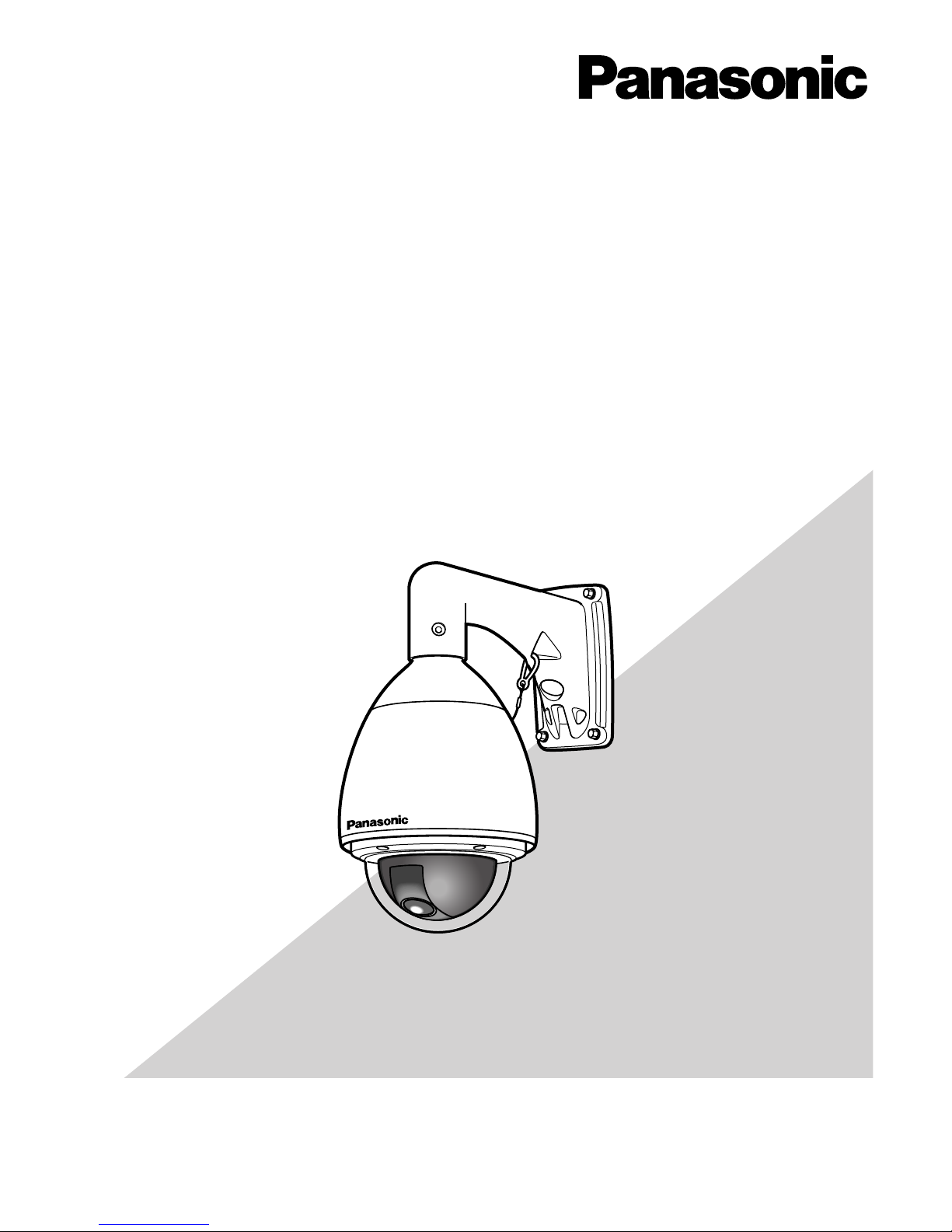
Front Cable Exit
1. Preparations
Specify the bracket fixing location, and then put in
four anchor bolts, or drill four bolt holes on the
installation surface. Refer to Dimensions on page 7.
2. Cable Bushing
Fit the supplied cable bushing into the front cable
exit of the bracket.
3. Cable Route
Route the connection cables from the front cable
exit through the bracket, and pull them out of the
pipe mouth.
4. Fixing Bracket
Fix the bracket to the wall using appropriate hardware (not supplied): bolts and nuts, anchor bolts
and nuts, or the like.
Mark hole positions
Cable Bushing
Fixing Hardware
(Locally Procured)
■ Introduction
This bracket is used for mounting the colour camera WV-CW960 or WV-CW964 onto a wall.
There are two ways of cable exit available from the front or rear of the bracket.
Precautions
• Make sure that the place you are installing the camera is strong enough to support it. If it is not strong enough, then the camera may fall and hurt someone.
• The following steps of installation and connection work should be done by qualified service personnel or system installers
and should conform to all local codes.
• Be sure to turn the power off before installation and connection.
• Do not install the camera near the air outlet of an air conditioner.
-3-
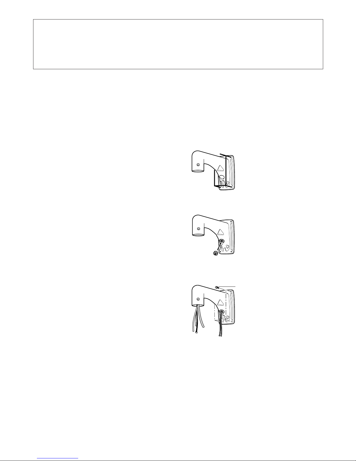
5. Disassembly of Camera
(1) Remove the upper base from the camera by
loosening 3 screws. The screws that are
removed need to be used during reassembly.
Be careful to not lose them. Turn the upper base
and separate it.
* Special screw (mounting screw): Use a hexa-
gon wrench for the hexagon screw (M6).
(2) Remove the attachment pipe from the upper
base by loosening 4 screws.
* Special screw (mounting screw): Use a hexa-
gon wrench for the hexagon screw (M6).
6. Setting Switches
Refer to DIP SWITCH SETTINGS in the manual
included with the camera.
7. Cable Connection
Refer to CONNECTIONS in the manual included
with the camera.
Warning: Seal the cables with plastic or rubber
tape to prevent it from being exposed.
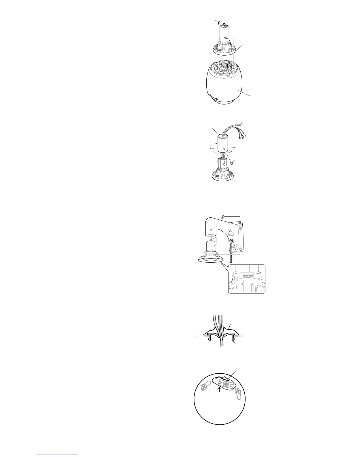
8. Mounting Upper Base
Fix the upper base to the bracket.
• Fasten 4 screws (the screws that were removed in
step (2) of “5. Disassembly of Camera”) making
sure that “REAR” engraved on the upper base faces
the wall.
9. Waterproofing
Fill the front cable exit with sealant.
Warning: Carefully apply the sealing so that water
or moisture cannot get inside. If water gets
inside the camera it could cause a shock or fire.
Also, if moisture gets inside the camera it could
cause the dome to become foggy.
10. Mounting Camera
(1) Aim the START arrow at the bent portion of the
leaf spring on top of the camera.
START
Sealant
Cable Bushing
Outside
Inside the bracket
Cables
Upper Base
Attachment Pipe
Camera Fixing Screw
x4
Upper Base
Bending
Leaf Spring
Camera
x3
x4
 Loading...