

Page 1
FEATURES
Wall Mount Bracket
Instructions
Model Nos.
WV-Q118/WV-Q118E
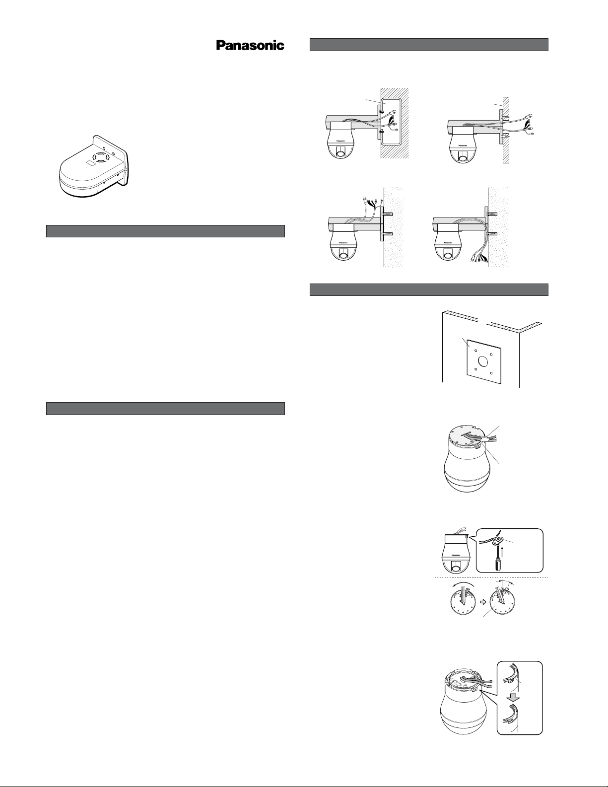
PLACES OF INSTALLATION
AM0205-0 3TR003444AAA Printed in Japan
Wall box
● Wall Box
Wood Siding Board
Strong enough to support the
camera weight
(approx. 3 kg {6.60 lbs})
● Wood Siding Board
Concrete slab Concrete slab
● Concrete
Template
(provided)
Wall
1
Make four holes in the wall using the template
(provided).
Protection Cover
(provided)
Part to be cut
2
Wrap the camera cables with the Protection
Cover (provided) as appropriate to the
Diecast Case.
INSTALLATION
Cut here
4
Cut the Diecast Case as shown.
Note: Be sure to protect the Video and Power
Cables with the Protection Cover
(
provided).
Mounting
Screw
Rotate
15°
Remove the Camera Mounting
Base by pulling up.
3
Remove the Mounting Screw (M3, provided),
pull up the Camera Mounting Base off the
camera, and turn the camera counterclockwise.
The Wall Mount Bracket WV-Q118 is provided for
mounting the Combination Camera WV-CS950 or
WV-CS954 onto the wall.
There are various ways of installing the camera as shown below.
Before attempting to connect or install this product,
please read these instructions carefully and
save this manual for future use.
• Fasten the bracket to a ceiling strong enough
to support the camera weight (approx. 3
kg.{6.60 lbs}).
• Wipe the bracket regularly using a soft and
dry cloth, or a cloth moistened with a water
solution of an ordinary kitchen detergent.
• Do not use chemicals for cleaning the enclosure as it may damage the surface.
• All the necessary steps required for installing
this product must be taken by a qualified service person or system installer.
PRECAUTIONS
• Be sure to use the Fall Prevention Wire.
• Do not use this bracket with any equipment
other than the WV-CS950 and the WV-CS954.
• Follow all applicable local and national electrical, fire and safety codes when installing
the camera with this ceiling mount bracket.
The model numbers in this Operating Instructions are shown without suffix.
UT+O//6.3,0,0 /1826ɚĘȸ /
Page 2
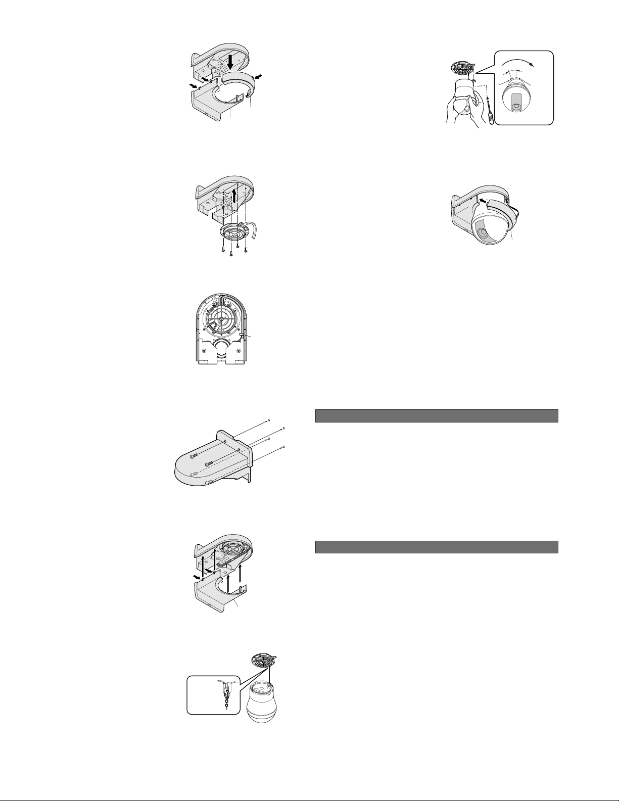
Decoration cover (1)
Decoration cover (2)
5
Remove the Decoration Cover in order (1)
then (2).
The Decoration Cover can be removed by
pressing on the points (1) at one place, and
(2) at 4 places.
6
Fix the Camera Mounting Base (provided with
the camera) to the bracket with the four M4L8 Screws (provided).
Note: Be sure to fix the Camera Mounting Base in
the up direction as shown.
Clamp
7
Run the cable around the outside and secure
it with the clamp.
Secure the cable with the clamp so it goes
along the inside of the top case so it does not
get in the way when attaching the case and
installing the camera.
8
Attach the top case to the wall and run the
cables.
Attach it with four screws. Screws are not
provided. Align it with the position the camera
will be installed.
Decoration cover (2)
9
Place the removed Decoration Cover(2) back
on the bracket and camera.
Note: Push the Decoration Cover up till it fits
over the bracket with a click.
Ring of the Fall
Prevention Wire
10
Suspend the Fall Prevention Wire from the
Camera Mounting Base.
Notes:
• Make sure that the wire matches the Fall
Prevention Wire Fixing Angle.
• The bracket is not shown in the illustration.
15
°
Camera
Mounting
Base
Camera
Rotate
Press up
11
Attach the camera to the Camera Mounting
Base, turn the camera clockwise, and
tighten the Mounting Screw (M3, provided).
Notes:
• Tigthen the Camera Fixing Screw with a
screwdriver.
• In attaching the camera to the Camera
Mounting Base, loosen the Camera Fixing
Screw (M3), then tighten it back with a screwdriver while keeping it pushed up.
• The bracket is not shown in the illustration.
Decoration cover (1)
12
Place the removed Decoration Cover (1)
back on the bracket and camera.
Note: Push the Decoration Cover up till it fits over
the bracket with a click.
Ambient Operating Temperature: 10˚C - +50˚C {14˚F – 122˚F}
Dimensions: 165 (W) x 140 (H) × 217.5 (D) mm
{6-1/2” (W) x 5-33/64” (H) × 8-37/64” (D)}
Weight: 650 g {1.43 lbs}
Weight and dimensions indicated are approximate.
Specifications are subject to change without notice.
SPECIFICATIONS
STANDARD ACCESSORIES
Screw (M4-L8) ..................................................... 4 pcs.
Template ................................................................. 1pc.
Protection Cover ..................................................... 1pc.
© 2005 Matsushita Electric Industrial Co., Ltd. All rights reserved.
For European and other fields:
Matsushita Electric Industrial Co., Ltd.
Osaka, Japan
http://www.panasonic.co.jp/global/
For U.S. , Canadian and Puerto Rican fields:
Panasonic System Solutions Company,
Unit Company of Panasonic Corporation of North
America
Security Systems
www.panasonic.com/security
For customer support, call 1.877.733.3689
Executive Office: Three Panasonic Way 2H-2,
Secaucus, New Jersey 07094
Zone Office
Eastern: Three Panasonic Way, Secaucus, New
Jersey 07094
Central: 1707 N. Randal Road, Elgin, IL 60123
Southern: 1225 Northbrook Parkway, Suwanee,
GA 30024
Western: 6550 Katella Ave., Cypress, CA 90630
PANASONIC CANADA INC.
5770 Ambler Drive,Mississauga,
Ontario, L4W 2T3 Canada (905) 624-5010
http://www.panasonic.ca
Panasonic Sales Company
Division of Panasonic Puerto Rico Inc.
San Gabriel Industrial Park 65th Infantry Ave. KM.
9.5 Carolina, P.R. 00985 (809) 750-4300
UT+O//6.3,0,0 /1826ɚĘȸ 1
 Loading...