

Page 1
-1-
Alarm Board
WV-PB5564
Before attempting to connect or operate this product, please read these instructions completely
PREFACE
The WV-PB5564 Alarm Board is provided for expanding the system capability of the Matrix
Switcher.
When handling this board, hold only by circuit board edges. Otherwise components on the
board may be damaged by static electricity.
Caution
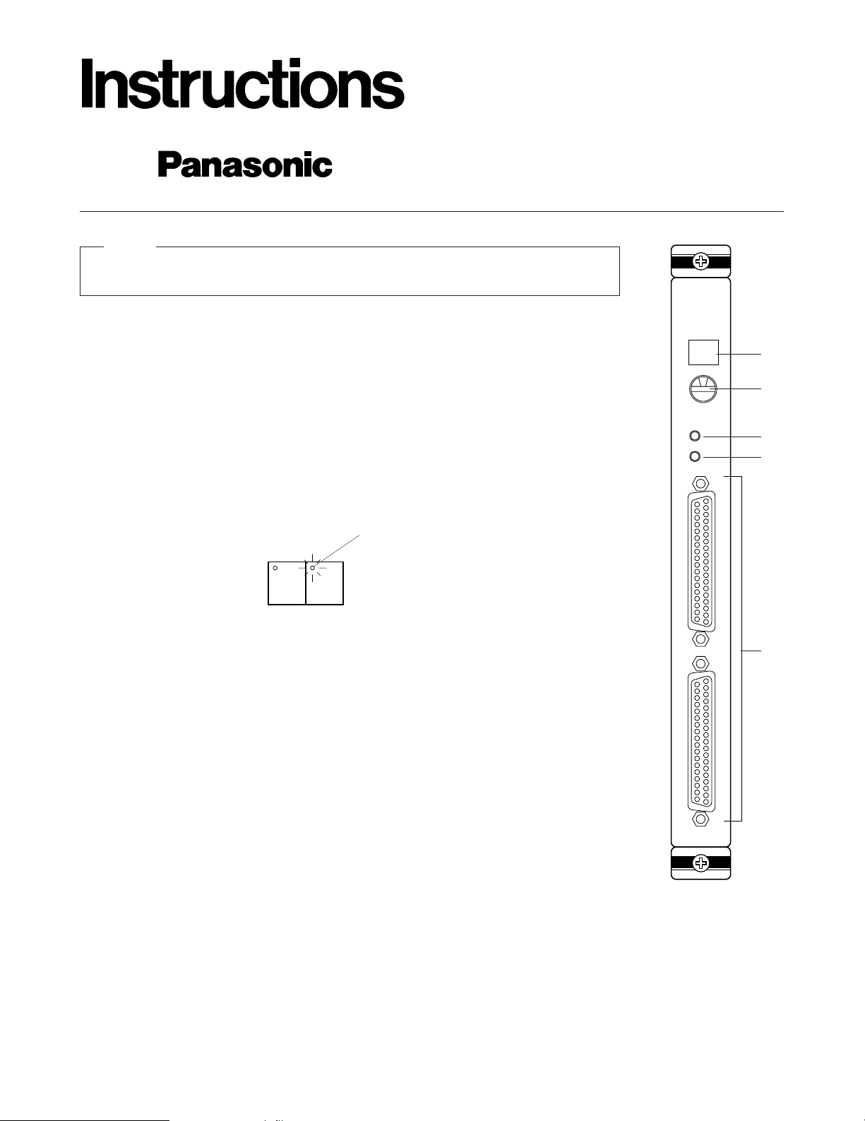
2. Mode Selection Switch (MODE)
This rotary switch, in combination with the test switch, is used to select the alarm test mode.
Mode 0: Press the Test Switch to receive, from memory, a chronologically organized display (in
the Alarm Number Display) of all alarms received from the Alarm Input Connector.
Mode 1: Press the Test Switch to simulate receiving alarm inputs 1-64 in ascending order, one
alarm per second. Use this mode to test the system for Alarm Mode-1, Mode-2 or Mode-3
set up.
Mode 2: Press the Test Switch to simulate receiving alarm inputs 1-64 all at the same time. Use
this mode to test the system for Alarm Mode-1, Mode-2 or Mode-3 set up.
Mode 3-9: These modes are not available.
Note: The alarm inputs 65-128 are activated above modes if the SW1 on the board is set at
alarm number 65-128. Refer to the BOARD SETTING on page 2.
3. Test Switch (TEST)
This switch is used to run the alarm test mode in combination with the Mode Selection Switch.
4. Reset Switch (RESET)
This switch is used to stop the alarm test mode or clear alarm the records from the internal
memory.
33-64
ALARM
TEST
1-32
00
5
RESET
MODE
q
w
e
r
t
APPEARANCE
1. Alarm Number display
This display indicates the of alarm input number when the associated alarm sensor unit is activated.
Note: The display indicator lights up as shown below When the alarm number is over one hun-
dred.
0 0
indicator
Page 2
-2-
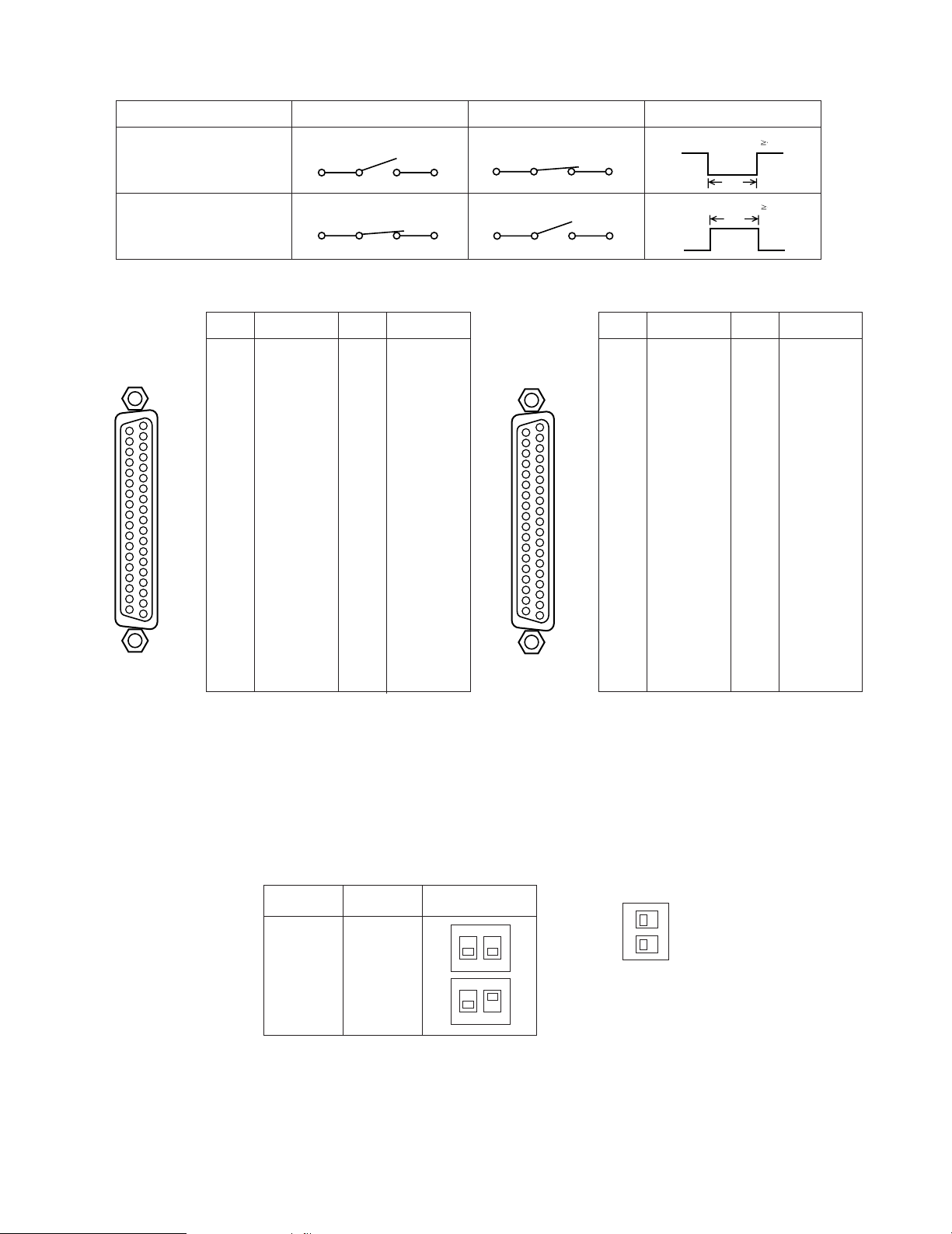
(Close) Alarm Sensor(Open) Alarm Sensor
Normal Condition Alarm In Alarm Signal
Normally Open
(NOR OPEN)
t 100 msec.
≧
Normally Closed
(NOR CLOSE)
(Close) Alarm Sensor (Open) Alarm Sensor
t 100 msec.
≧
t
0V
0V
t
Pin No.Pin No.
1
2
3
4
5
6
7
8
9
10
11
12
13
14
15
16
17
18
19
Alarm 1(65)
Alarm 2(66)
Alarm 3(67)
Alarm 4(68)
Alarm 5(69)
Alarm 6(70)
Alarm 7(71)
Alarm 8(72)
Alarm 9(73)
Alarm 10(74)
Alarm 11(75)
Alarm 12(76)
Alarm 13(77)
Alarm 14(78)
Alarm 15(79)
Alarm 16(80)
Alarm 17(81)
Alarm 18(82)
Alarm 19(83)
Designation
20
21
22
23
24
25
26
27
28
29
30
31
32
33
34
35
36
37
Pin No.
Alarm 20(84)
Alarm 21(85)
Alarm 22(86)
Alarm 23(87)
Alarm 24(88)
Alarm 25(89)
Alarm 26(90)
Alarm 27(91)
Alarm 28(92)
Alarm 29(93)
Alarm 30(94)
Alarm 31(95)
Alarm 32(96)
Not used
Not used
Not used
Ground
Ground
Designation
1
2
3
4
5
6
7
8
9
10
11
12
13
14
15
16
17
18
19
Alarm 33(97)
Alarm 34(98)
Alarm 35(99)
Alarm 36(100)
Alarm 37(101)
Alarm 38(102)
Alarm 39(103)
Alarm 40(104)
Alarm 41(105)
Alarm 42(106)
Alarm 43(107)
Alarm 44(108)
Alarm 45(109)
Alarm 46(110)
Alarm 47(111)
Alarm 48(112)
Alarm 49(113)
Alarm 50(114)
Alarm 51(115)
Designation
20
21
22
23
24
25
26
27
28
29
30
31
32
33
34
35
36
37
Pin No.
Alarm 52(116)
Alarm 53(117)
Alarm 54(118)
Alarm 55(119)
Alarm 56(120)
Alarm 57(121)
Alarm 58(122)
Alarm 59(123)
Alarm 60(124)
Alarm 61(125)
Alarm 62(126)
Alarm 63(127)
Alarm 64(128)
Not used
Not used
Not used
Ground
Ground
Designation
1-32
37
20
19
1
33-64
37
20
19
1
BOARD SETTING
Before installing this board, the following settings should be made by qualified service personnel or system installers.
1. Set switches (SW1) on the board to meet the alarm input number as shown below.
BOARD
NO.
12
OFF
12
OFF
1
2
1-64
65-12
ALARM
INPUT NO.
SW1 SETTING
1
2
OFF
SW1
UNIT ADR
5. Alarm Input Connector (1-32, 33-64)
This connector accepts the alarm signals, either normally open or normally closed, from the associated alarm sensor unit.
Page 3

-3-
3. Confirm switchers (SW12) on the board are set to the following positions.
12
OFF
SW12
These switches are used only for factory test.
Always keep these switches in the "OFF" positions in the
field.
Note
2. Set switches (SW4 - SW11) on the board to meet the
alarm input requirements. Initially, normally open
(NOR, OPEN) positions are selected at the factory.
12345678
OFF
SW4
NOR
CLOSE
NOR
OPEN
1
12345678
OFF
SW5
2
1
2
3
4
5
6
7
8
SW4
SW5
SW6
SW7
SW8
SW9
SW10
SW11
Switch No.
1 - 8 (65-72)
9 - 16 (73-80)
17 - 24 (81-88)
25 - 32 (89-96)
33 - 40 (97-104)
41 - 48 (105-112)
49 - 56 (113-120)
57 - 64 (121-128)
Alarm Input
The following installation should be made by qualified service personnel or system installers.
1. Remove the screws on the rear panel(s) of the Matrix
Switcher.
2. Remove the rear panel(s).
3. Place the Alarm Board into the desired position in the
rear of Matrix Switcher by sliding it inside the board
quides.
INSTALLATION
Before installing this board be sure to turn off the Power
Switch of the Matrix Switcher.
Caution
Each slot is identical, so the board can installed in any
slot.
However it is recommended to install the board as
shown below for an orderly installation.
Note
Rear Panel(s)
Remove screws.
OFF
12
SW1
UNIT ADR
OFF
12
1
SW4
2
SW5
3
SW6
4
SW7
5
SW8
6
SW9
7
SW10
SW12
8
SW11
Page 4

4. Make sure to push in the Alarm Board until it is seated
firmly.
5. Secure the Alarm Board by tightening the two screws
on the board.
6. Close off open spaces on the rear of the Matrix
Switcher by using Blank Panels WV-Q63 (Optional) or
supplied rear panel(s).
(Refer to the instructions for WV-Q63)
Refer to the Operating Instructions of WJ-SX550A for
more details.
Note
Alarm Board WV-PB5564
Video Input
Board
Video Output
Board
CPU
RS-232C
TIME
ADJUST IN
COM
PRINTER
OUT
IN
VS/VD
VD
OUT
OFF
+9V
+5V
−
5V
POWER
ON
11A00001
OUT
IN
1
OUT
IN
2
OUT
IN
3
OUT
IN
4
MONITOR
ALARM OUT
RESET OUT
EXT TIMING IN
RECOVER IN
OUTPUT
MONITOR
ALARM OUT
RESET OUT
EXT TIMING IN
RECOVER IN
MONITOR
ALARM OUT
RESET OUT
EXT TIMING IN
RECOVER IN
MONITOR
ALARM OUT
RESET OUT
EXT TIMING IN
RECOVER IN
OUT
IN
1
OUT
IN
2
OUT
IN
3
OUT
IN
4
OUTPUT
OUT
IN
1
OUT
IN
2
OUT
IN
3
OUT
IN
4
OUTPUT
OUT
IN
1
OUT
IN
2
OUT
IN
3
OUT
IN
4
OUTPUTINPUT
1
2
3
4
5
6
7
8
CAMERA IN
VIDEO OUT1
VIDEO OUT2
INPUT
1
2
3
4
5
6
7
8
CAMERA IN
VIDEO OUT1
VIDEO OUT2
INPUT
1
2
3
4
5
6
7
8
CAMERA IN
VIDEO OUT1
VIDEO OUT2
INPUT
1
2
3
4
5
6
7
8
CAMERA IN
VIDEO OUT1
VIDEO OUT2
INPUT
1
2
3
4
5
6
7
8
CAMERA IN
VIDEO OUT1
VIDEO OUT2
INPUT
1
2
3
4
5
6
7
8
CAMERA IN
VIDEO OUT1
VIDEO OUT2
INPUT
1
2
3
4
5
6
7
8
CAMERA IN
VIDEO OUT1
VIDEO OUT2
INPUT
1
2
3
4
5
6
7
8
CAMERA IN
VIDEO OUT1
VIDEO OUT2
33-64
ALARM
TEST
1-32
00
5
RESET
MODE
CONTROL
DATA 1
DATA 2
DATA 3
DATA 4
DATA 5
DATA 6
DATA 7
DATA 8
TEST 1
TEST 2
Blank Panel
or
Tighten screws.
Tighten screws.Alarm Board
SPECIFICATIONS
Alarm Input (1 - 64): Normally open or normally closed selectable
(contact time more than 100 msec.)
37 pin D-Sub connector (x2)
Dimensions: 24.5(W) x 265(H) x 260(D) mm
15/16"(W) x 10-7/16"(H) x 10-1/4"(D)
Weight: 400
g (0.9 lbs.)
Weight and dimensions indicated are approximate.
specifications are subject to change without notice.
N0494-1026 YWV8QA3313BN Printed in Japan
N 19
Broadcast & Television Systems Company
Division of Matsushita Electric Corporation of America
IMAGING SYSTEMS DIVISION
Executive Office: One Panasonic Way 3E-7, Secaucus, New Jersey 07094
Regional Offices:
Northeast: 43 Hartz Way, Secaucus, NJ 07094 (201) 348-7303
Southeast: 1225 Northbrook Parkway, Suite 1-160, Suwanee, GA 30174 (404) 338-6835
Midwest: 1707 North Randall Road, Elgin, IL 60123 (708) 468-5200
Southwest: 4500 Amon Carter Blvd., Fort Worth, TX 76155 (817) 685-1117
Western: 6550 Katella Ave. 17A-5, Cypress, CA 90630 (714) 373-7265
MATSUSHITA ELECTRIC OF CANADA LIMITED
5770 Ambler Drive, Mississauga, Ontario, L4W 2T3 Canada (905)624-5010
PANASONIC SALES COMPANY
DIVISION OF MATSUSHITA ELECTRIC OF PUERTO RICO, INC.
San Gabriel Industrial Park, 65th Infantry Ave. KM. 9.5 Carolina, Puerto Rico 00630 (809)750-4300
 Loading...