

Page 1
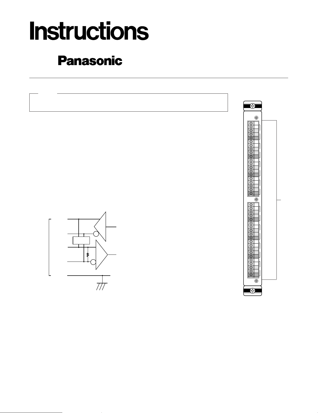
Data Board
WV-PB5548
Before attempting to connect or operate this product, please read these instructions completely
PREFACE
The WV-PB5548 Data Board is used to transmit/receive only control data between the Matrix
Switcher and the camera site.
When handling this board, hold only by circuit board edges. Otherwise components on the
board may be damaged by static electricity.
Caution
APPEARANCE
1. Data Connector (TA/TB/RA/RB/GND, 1 - 8)
These connectors are used to transmit/receive control data to/from the camera site. Use data
grade cable, suitable for RS-485 (shielded, twisted pairs). Cable length may be extended up to
1,200 m (4,000 ft).
TXD
TB
RA (+)
RB
GND
RXDRT
TA (+)
S W
1
DATA
(RS485)
A
T
B
1
A
R
B
G
A
T
B
2
A
R
B
G
A
T
B
3
A
R
B
G
A
T
B
4
A
R
B
G
A
T
B
5
A
R
B
G
A
T
B
6
A
R
B
G
A
T
B
7
A
R
B
G
A
T
B
8
A
R
B
G
q
RT: Termination Resistor, 150Ω 1/2W
SW: Selection Switch, Full Duplex/ Half Duplex
GND: Ground; Connected to each channel and
common ground.
Page 2
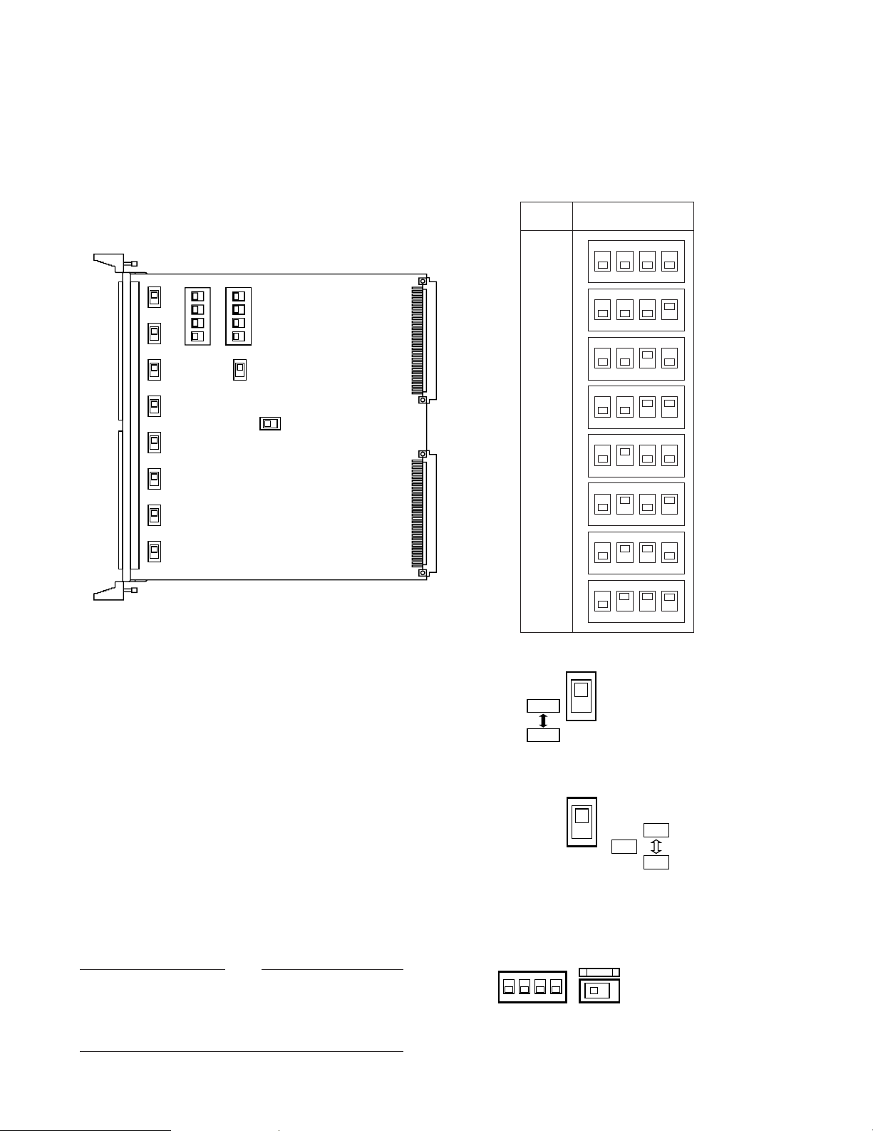
BOARD SETTING
Before installing this board, the following settings should be made by qualified service personnel or system installers.
1234
OFF
SW1
1234
OFF
SW3
SW100
SW150
SW200
SW250
SW300
SW350
SW400
SW450
SW5
SW6
BOARD
NO.
1234
OFF
1234
OFF
1234
OFF
1234
OFF
1234
OFF
1234
OFF
1234
OFF
1234
OFF
1
2
3
4
5
6
7
8
SW1 SETTING
1. Set switches (SW1) on the board to meet the data
board number as shown in the following table.
Initially, board number 1 is selected at the factory.
2. Set switches (SW100/SW150/SW200/SW250/SW300/
SW350/SW400/SW450) on the board to choose the
communication lines as either Full Duplex (FULL) or
Half Duplex (HALF).
Initially, Full Duplex(FULL) positions are selected at
the factory.
3. Set switch (SW5) on the board to choose the LED indicator as either “ON” or “OFF” mode. The indicator displays that the control data are activated normally on
the board.
Initially, “ON” position is selected at the factory.
4. Confirm switches (SW3/SW6) on the board are set to
the following positions.
SW100 - SW450
FULL
HALF
SW5
ON
OFF
LED
1234
OFF
SW3
SW6
12PROG
Full: 4 Lines
Half: 2 Lines
These switches are used only for factory test.
Always keep these switches in these positions in the
field.
Note
-2-
Page 3
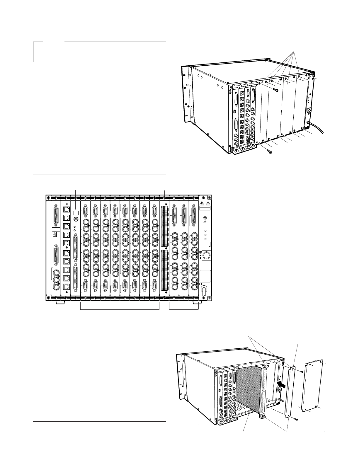
4. Make sure to push in the Data Board until it is seated
firmly.
5. Secure the Data Board by tightening the two screws
on the board.
6. Close off open spaces on the rear of the Matrix
Switcher by using WV-Q63 Blank Panels (Optional) or
supplied rear panel(s).
(Refer to the instructions for WV-Q63)
INSTALLATION
Before installing this board be sure to turn off the Power
Switch of the Matrix Switcher.
Caution
Each slot is identical, so the board can installed in any
slot.
However it is recommended to install the board as
shown below for an orderly installation.
Note
CPU
RS-232C
TIME
ADJUST IN
COM
PRINTER
OUT
IN
VS/VD
VD
OUT
OFF
+9V
+5V
−
5V
POWER
ON
11A00001
MONITOR
ALARM OUT
RESET OUT
EXT TIMING IN
RECOVER IN
MONITOR
ALARM OUT
RESET OUT
EXT TIMING IN
RECOVER IN
MONITOR
ALARM OUT
RESET OUT
EXT TIMING IN
RECOVER IN
OUT
IN
1
OUT
IN
2
OUT
IN
3
OUT
IN
4
OUTPUT
OUT
IN
1
OUT
IN
2
OUT
IN
3
OUT
IN
4
OUTPUT
OUT
IN
1
OUT
IN
2
OUT
IN
3
OUT
IN
4
OUTPUTINPUT
1
2
3
4
5
6
7
8
CAMERA IN
VIDEO OUT1
VIDEO OUT2
INPUT
1
2
3
4
5
6
7
8
CAMERA IN
VIDEO OUT1
VIDEO OUT2
INPUT
1
2
3
4
5
6
7
8
CAMERA IN
VIDEO OUT1
VIDEO OUT2
INPUT
1
2
3
4
5
6
7
8
CAMERA IN
VIDEO OUT1
VIDEO OUT2
INPUT
1
2
3
4
5
6
7
8
CAMERA IN
VIDEO OUT1
VIDEO OUT2
INPUT
1
2
3
4
5
6
7
8
CAMERA IN
VIDEO OUT1
VIDEO OUT2
INPUT
1
2
3
4
5
6
7
8
CAMERA IN
VIDEO OUT1
VIDEO OUT2
INPUT
1
2
3
4
5
6
7
8
CAMERA IN
VIDEO OUT1
VIDEO OUT2
33-64
ALARM
TEST
1-32
00
5
RESET
MODE
CONTROL
DATA 1
DATA 2
DATA 3
DATA 4
DATA 5
DATA 6
DATA 7
DATA 8
TEST 1
TEST 2
DATA
(RS485)
A
T
B
1
A
R
B
G
A
T
B
2
A
R
B
G
A
T
B
3
A
R
B
G
A
T
B
4
A
R
B
G
A
T
B
1
A
R
B
G
A
T
B
2
A
R
B
G
A
T
B
3
A
R
B
G
A
T
B
4
A
R
B
G
Alarm Board
Video Input Board
Video Output
Board
Rear Panel(s)
Remove screws.
Blank Panel
or
Tighten screws.
Tighten screws.
Data Board
The following installation should be made by qualified service personnel or system installers.
1. Remove the screws from the rear panel(s) of the
Matrix Switcher.
2. Remove the rear panel(s).
3. Place the Data Board into the desired position in the
rear of Matrix Switcher by sliding it inside the board
guides.
Data Board
-3-
Refer to the Operating Instructions of WJ-SX550A for
further details.
Note
Page 4

-4-
CONNECTIONS
Connect the Data Board and the Camera Controller by
specified data cable.
Basically, connect shown right.
DATA
(RS485)
A
T
B
1
A
R
B
G
A
T
B
2
A
R
GND
DATA
T(A) T(B) R(A) R(B)
Then the following settings should be made by using the
Setup Menu.
• Camera Controller
Set Up
F1:-- F2:-- F3:DEL F4:Pop
System RS-485
RS-485
Site Communication
#1
Up
#2
Daisy
#3
#4
#5
#6
#7
#8
Number
F/H
Duplex
Delay
Time
Baud
Rate
Wait
Time
02
04
06
10
Off
Off
100
Off
Off
Off
Off
Off
Off
Off
Off
Off
Off
Off
Stop
Bit
1
1
1
1
1
1
1
1
Parity
Check
None
None
None
None
None
None
None
None
Data
Bit
8
8
8
8
8
8
8
8
When Daisy Mode is "on" only #1 will be available
Off
19200
9600
19200
19200
1200
19200
19200
19200
Full
Half
Full
Full
Full
Full
Full
Full
Camera In
Off
Off
Board Addr. 1
** Communication **
Unit Number 1
Baud Rate 19200
Data Bit 8
Parity Check None
Stop Bit 1
Xon/Xoff Not Use
Wait Time Off
Delay Time Off
Alarm Data Off
Return
■ Direct Connection between the Data Board and Camera Controllers
In this type of connection there is one control cable directly connecting each Data Connector to the WV-RM70 Camera
Controller. Refer to the connections and settings shown below.
• 4 Line (Full Duplex) Connection
TXD
TB
RA (+)
RB
GND
RXD
TA (+)
DATA
(RS485)
A
T
B
1
A
R
B
G
A
T
B
2
A
R
B
G
A
T
B
3
A
R
B
G
A
T
B
4
A
R
B
G
A
T
B
5
A
R
B
G
A
T
B
6
A
R
B
G
A
T
B
7
A
R
B
G
A
T
B
8
A
R
B
G
R(A)
R(B)
GND
T(A)
T(B)
GND
S W
SW100, 150, 200, 250
300, 350, 400, 450
FULL: 4 lines
(Internal Switch: SW5, 4 line)
TA (+)
TB
RA (+)
RB
GND
1
TA (+)
TB
RA (+)
RB
GND
2
TA (+)
TB
RA (+)
RB
GND
3
TA (+)
TB
RA (+)
RB
GND
4
TA (+)
TB
RA (+)
RB
GND
5
TA (+)
TB
RA (+)
RB
GND
6
TA (+)
TB
RA (+)
RB
GND
7
TA (+)
TB
RA (+)
RB
GND
8
Combination
Camera
Reciver
Page 5

8
Models
Parameters
-5-
• 2 Line (Half Duplex) Connection
Set the same Communication Parameters on the Setup Menus of the Matrix Switcher and Camera Controller.
TXD
TB
RA (+)
RB
GND
RXD
TA (+)
DATA
(RS485)
A
T
B
1
A
R
B
G
A
T
B
2
A
R
B
G
A
T
B
3
A
R
B
G
A
T
B
4
A
R
B
G
A
T
B
5
A
R
B
G
A
T
B
6
A
R
B
G
A
T
B
7
A
R
B
G
A
T
B
8
A
R
B
G
R(A)
R(B)
GND
T(A)
T(B)
GND
S W
SW100, 150, 200, 250
300, 350, 400, 450
HALF: 2 lines
(Internal Switch: SW5, 2 lines)
TA (+)
TB
RA (+)
RB
GND
1
TA (+)
TB
RA (+)
RB
GND
2
TA (+)
TB
RA (+)
RB
GND
3
TA (+)
TB
RA (+)
RB
GND
4
TA (+)
TB
RA (+)
RB
GND
5
TA (+)
TB
RA (+)
RB
GND
6
TA (+)
TB
RA (+)
RB
GND
7
TA (+)
TB
RA (+)
RB
GND
8
Combination
Camera
Reciver
Baud Rate
Matrix Switcher
WJ-SX550A
Camera Controller
WV-RM70
F/H Duplex : Full or Half
Data Bit
19200 19200
Parity Check
8
Stop Bit
None Fixed None
Wait time
11
Delay Time
Off Off
Off Off
Xon/Xoff : Not use
Alarm Data : On
Daisy : Off Unit Number : Not use
Page 6

-6-
■ Indirect Connection between the Data Board and Camera Controllers
(“Daisy-Chain” Type Wiring)
In this type of connection only one control cable directly connects between the Data Connector #1 and the Camera Controller
#1. The rest of the Camera Controllers connect to Camera Controller #1 in a Daisy-Chain of connection. Refer to the connections and settings shown below.
• 4 Line (Full Duplex) Connection
TXD
TB
RA (+)
RB
GND
RXD
TA (+)
DATA
(RS485)
A
T
B
1
A
R
B
G
A
T
B
2
A
R
B
G
A
T
B
3
A
R
B
G
A
T
B
4
A
R
B
G
A
T
B
5
A
R
B
G
A
T
B
6
A
R
B
G
A
T
B
7
A
R
B
G
A
T
B
8
A
R
B
G
R(A)
R(B)
GND
T(A)
T(B)
GND
S W
SW100, 150, 200, 250
300, 350, 400, 450
FULL: 4 lines
(Internal Switch: SW5, 4 lines)
TA (+)
TB
RA (+)
RB
GND
1
2
3
4
5
8
Combination
Camera
Reciver
R(A)
R(B)
GND
T(A)
T(B)
GND
R(A)
R(B)
GND
T(A)
T(B)
GND
R(A)
R(B)
GND
T(A)
T(B)
GND
R(A)
R(B)
GND
T(A)
T(B)
GND
R(A)
R(B)
GND
T(A)
T(B)
GND
Page 7

-7-
It is only available an alarm data connected unit in a
Daisy-Chain. Set the Mode Selection Switch on the one
of Camera Controllers to the “NORMAL” position and
the others are set to the “ALARM OFF” positions.
Caution
It is not available 2 Line (Half Duplex) connection in a
Daisy-Chain.
Note
SPECIFICATIONS
Data Input/Output(1 - 8): RS-485 (Full Duplex or Half Duplex, selectable inside the switch)
[5-pin T(A), T(B), R(A), R(B), GND] X8
use with shield, twisted pairs data cable
Transmitting Speed (Baud Rate); 1200 - 19200 bps
Max. Cable Length: 1,200 m (4,000 ft)
Max. Number Boards: 8 (Address 1 - 8, Total 1 - 64 Data Input/Output)
Dimensions: 24.5 (W) x 265 (H) x 260 (D) mm
15/16” (W) x 10-7/16” (H) x 10-1/4” (D)
Weight: 400
g (0.9 lbs.)
Weight and dimensions indicated are approximate.
Specifications are subject to change without notice
Matrix Switcher
WJ-SX550A
Camera In Number #4 - - -
Camera In Number #2 - - -
Set the Matrix Switcher and the Camera Controllers (up to 8) shown below.
Models
Parameters
Daisy : On
Camera Controller
WV-RM70
F/H Duplex : Full
Camera In Number #1 - - - Unit Number : 1
Unit Number : 2
Camera In Number #3 - - - Unit Number : 3
Unit Number : 4
Camera In Number #5 - - - Unit Number : 5
Camera In Number #6 - - - Unit Number : 6
Camera In Number #7 - - - Unit Number : 7
Camera In Number #8 - - - Unit Number : 8
Page 8

N0396-0 YWV8QA4196AN Printed in Japan
N 19
Broadcast & Television Systems Company
Division of Matsushita Electric Corporation of America
IMAGING SYSTEMS DIVISION
Executive Office: One Panasonic Way 3E-7, Secaucus, New Jersey 07094
Regional Offices:
Northeast: 43 Hartz Way, Secaucus, NJ 07094 (201) 348-7303
Southeast: 1225 Northbrook Parkway, Suite 1-160, Suwanee, GA 30174 (770) 338-6835
Midwest: 1707 North Randall Road, Elgin, IL 60123 (708) 468-5200
Southwest: 4500 Amon Carter Blvd., Fort Worth, TX 76155 (817) 685-1117
Western: 6550 Katella Ave. 17A-5, Cypress, CA 90630 (714) 373-7265
MATSUSHITA ELECTRIC OF CANADA LIMITED
5770 Ambler Drive, Mississauga, Ontario, L4W 2T3 Canada (905)624-5010
PANASONIC SALES COMPANY
DIVISION OF MATSUSHITA ELECTRIC OF PUERTO RICO, INC.
San Gabriel Industrial Park, 65th Infantry Ave. KM. 9.5 Carolina, Puerto Rico 00630 (809)750-4300
 Loading...