

Page 1
Video Input Board
WV-PB5508
Before attempting to connect or operate this product, please read these instructions completely
PREFACE
The Video Input Board WV-PB5508 is provided for expanding the video input capability of the Matrix
Switcher WJ-SX550.
When handling this board, hold only by circuit board edges. Otherwise components on the
board may be damaged by static electricity.
Caution
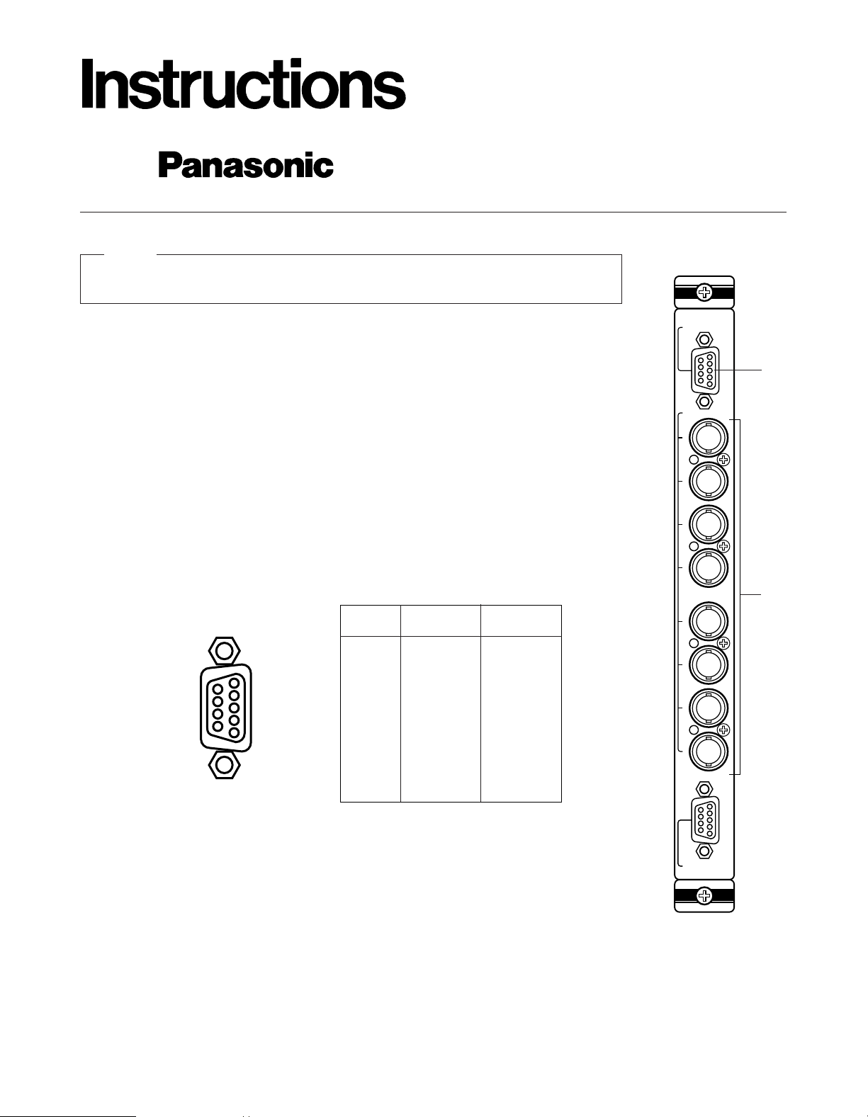
APPEARANCE
1. Video Output Connector (VIDEO OUT 1, 2)
The video signal connected to the Camera Input Connector (CAMERA IN) is looped through to
this connector with 75 ohms termination.
The camera control signal multiplexed on the video signal has been eliminated at this connector. When the Power Switch of the Matrix Switcher is turned off no signal is obtained at this connector.
BNC female connectors are available by use of optional loop through cable WV-CA64.
2. Camera Input Connector (CAMERA IN, 1 - 8)
This connector accepts either a color or B/W composite video signal from the camera.
Also VD2, to synchronize cameras in vertical timing, and data, to control camera site devices
such as receivers, intelligent cameras, and combination cameras, are multiplexed through this
connector.
Pin No.
1
2
3
4
5
6
7
8
9
Not used
CH1
GND (CH1)
CH2
GND (CH2)
CH3
GND (CH3)
CH4
GND (CH4)
Not used
CH5
GND (CH5)
CH6
GND (CH6)
CH7
GND (CH7)
CH8
GND (CH8)
VIDEO OUT1VIDEO OUT
2
9
8
7
6
5
4
3
2
1
INPUT
1
2
3
4
5
6
7
8
CAMERA IN
VIDEO OUT1
VIDEO OUT2
q
w
Page 2
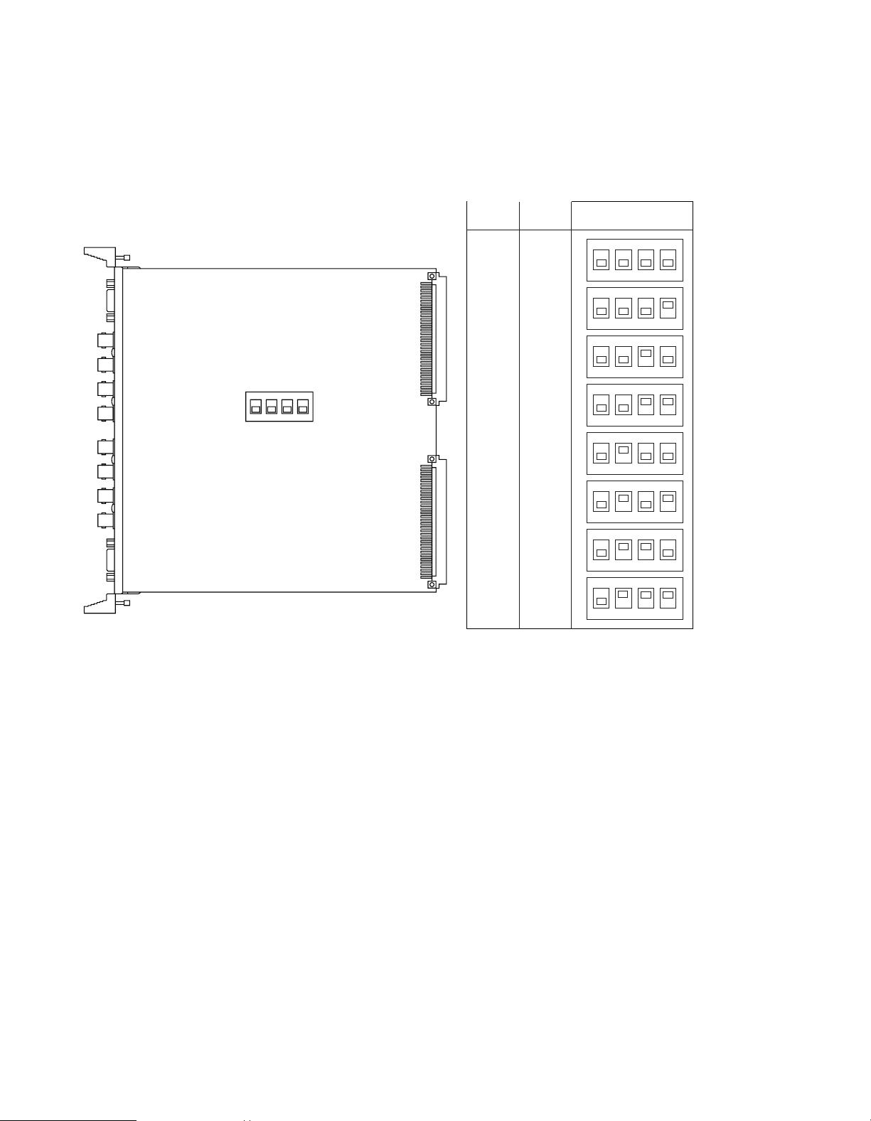
BOARD SETTING
Before installing this board, the following settings should be made by qualified service personnel or system installers.
Set switches (SW1) on the board to meet the camera input number as shown in the following table.
Initially, camera input 1-8 is selected at the factory.
1234
OFF
1234
OFF
1234
OFF
1234
OFF
1234
OFF
1234
OFF
1234
OFF
1234
OFF
BOARD
NO.
1
2
3
4
5
6
7
8
1-8
9-16
17-24
25-32
33-40
41-48
49-56
57-64
CAMERA
IN NO.
SW1 SETTING
1234
OFF
SW1
Page 3

3. Make sure to push in the Video Input Board until it is
seated firmly.
4. Secure the Video Input Board by tightening the two
screws on the board.
5. Close off open spaces on the rear of the Matrix
Switcher by using Blank Panels WV-Q63 (Optional).
(Refer to the instructions for WV-Q63)
INSTALLATION
Before installing this board be sure to turn off the Power
Switch of the Matrix Switcher WJ-SX550.
Caution
The following installation should be made by qualified service personnel or system installers.
1. Remove four screws on the rear panel of the Matrix
Switcher.
2. Place the Video Input Board into the desired position
in the rear of Matrix Switcher by sliding it inside the
board guides.
Each slot is identical, so the board can installed in any
slot.
However it is recommended to install the board as
shown below for an orderly installation.
Note
Refer to the Operating Instructions of WJ-SX550 for
more details.
Note
Rear Panel
Remove four
screws.
Blank Panel
Tighten screws.
Tighten screws.
Video Input Board
CONTROL
DATA 1
DATA 2
DATA 3
DATA 4
DATA 5
DATA 6
DATA 7
DATA 8
TEST 1
TEST 2
CPU
RS-232C
TIME
ADJUST IN
COM
PRINTER
OUT
IN
VS/VD
VD
OUT
OFF
+9V
+5V
−5V
POWER
ON
11A00001
OUT
IN
1
OUT
IN
2
OUT
IN
3
OUT
IN
4
MONITOR
ALARM OUT
RESET OUT
OUTPUT
OUT
IN
1
OUT
IN
2
OUT
IN
3
OUT
IN
4
MONITOR
ALARM OUT
RESET OUT
OUTPUT
OUT
IN
1
OUT
IN
2
OUT
IN
3
OUT
IN
4
MONITOR
ALARM OUT
RESET OUT
OUTPUT
OUT
IN
1
OUT
IN
2
OUT
IN
3
OUT
IN
4
MONITOR
ALARM OUT
RESET OUT
OUTPUTINPUT
1
2
3
4
5
6
7
8
CAMERA IN
VIDEO OUT1
VIDEO OUT2
INPUT
1
2
3
4
5
6
7
8
CAMERA IN
VIDEO OUT1
VIDEO OUT2
INPUT
1
2
3
4
5
6
7
8
CAMERA IN
VIDEO OUT1
VIDEO OUT2
INPUT
1
2
3
4
5
6
7
8
CAMERA IN
VIDEO OUT1
VIDEO OUT2
INPUT
1
2
3
4
5
6
7
8
CAMERA IN
VIDEO OUT1
VIDEO OUT2
INPUT
1
2
3
4
5
6
7
8
CAMERA IN
VIDEO OUT1
VIDEO OUT2
INPUT
1
2
3
4
5
6
7
8
CAMERA IN
VIDEO OUT1
VIDEO OUT2
INPUT
1
2
3
4
5
6
7
8
CAMERA IN
VIDEO OUT1
VIDEO OUT2
33-64
ALARM
TEST
1-32
00
5
RESET
MODE
125V 6A
Alarm Board
WV-PB5564
Video Input Board Video Output
Board
Page 4

Broadcast & Television Systems Company
Division of Matsushita Electric Corporation of America
CLOSED CIRCUIT VIDEO EQUIPMENT DIVISION
Executive Office: One Panasonic Way, Secaucus, New Jersey 07094
Regional Offices:
Northeast: 43 Hartz Way, Secaucus, NJ 07094 (201) 348-7303
Southeast: 1854 Shackleford Court, Suite 115, Norcross, CA 30003 (404) 717-6835
Midwest: 1707 North Randall Road, Elgin, IL 60123 (708) 468-5200
Southwest: 4500 Amon Carter Blvd., Ft. Worth, TX 76155 (817) 685-1117
Western: 6550 Katella Ave., Cypress, CA 90630 (714) 373-7265
MATSUSHITA ELECTRIC OF CANADA LIMITED
5770 Ambler Drive, Mississauga, Ontario, L4W 2T3 Canada (905)624-5010
PANASONIC SALES COMPANY
DIVISION OF MATSUSHITA ELECTRIC OF PUERTO RICO, INC.
San Gabriel Industrial Park, 65th Infantry, Ave. KM. 9.5 Carolina, Puerto Rico 00630 (809)750-4300
N0494-0 YWV8QA3315AN Printed in Japan
N 19
SPECIFICATIONS
Camera Input (1 - 8): 1.0 Vp-p/75 ohms composite video signal
0.5Vp-p/75 ohms data signal and 2.5 Vp-p/75 ohms vertical timing pulse multiplexed
Video Output (1 - 2): 1.0 Vp-p/75 ohms composite video signal
Dimensions: 15/16"(W) x 10-7/16"(H) x 10-1/4"(D)
24.5(W) x 265(H) x 260(D) mm
Weight: 1.0 lbs. (450g)
Weight and dimensions indicated are approximate.
specifications are subject to change without notice.
 Loading...