

Panasonic WV-PB5504A Operating Instructions
OUT
IN
OUT
IN
OUT
IN
OUT
IN
MONITOR
ALARM OUT
RESET OUT
EXT TIMING IN
RECOVER IN
OUTPUT
1
2
3
4
-1-
Video Output Board
WV-PB5504A
Before attempting to connect or operate this product, please read these instructions completely
PREFACE
The WV-PB5504A Video Output Board is provided for expanding the video output capability of the
Matrix Switcher.
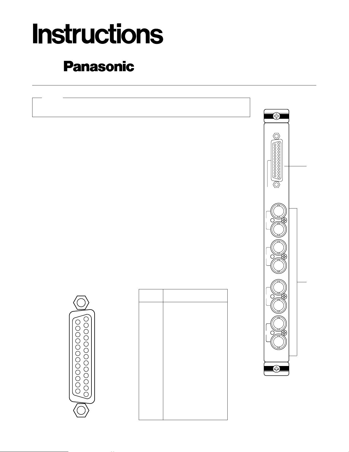
APPEARANCE
1. Alarm Output/Reset Output Connector (ALARM OUT/RESET OUT)
External Timing Input Connector (EXT TIMING IN)
Recover Input Connector (RECOVER IN)
ALARM OUT: When the Matrix Switcher receives an alarm from the WV-PB5564 Alarm Board or
camera site receivers WV-RC100 or WV-RC150, the alarm output signal is provided at this
connector for the Time Lapse VCR. The active pin number of the alarm output depends on
the alarm mode set by the on-screen program (Mode-1, Mode-2, Mode-3).
RESET OUT: When the Matrix Switcher resets the activated alarm, the alarm reset output sig-
nal, either Open Collector or pulse, is provided at this connector for the Time Lapse VCR.
EXT TIMING IN: The camera switching interval (Sequential Dwell Time) can be synchronized
with the lapse mode set in the Time Lapse VCR.
EXT. TIMING IN 1 controls Monitor 1 output, EXT. TIMING IN 2 controls Monitor 2 output, etc.
Supply the camera switching pulse from the Time Lapse VCR to this connector. Minimum
duration for camera switching pulse needs to be more than one (1) second.
RECOVER IN: This connector accepts the alarm recover signal from the Time Lapse VCR.
When handling this board, hold only by circuit board edges. Otherwise components on the
board may be damaged by static electricity.
Caution
q
w
25
13
24
23
22
21
20
19
18
17
16
15
14
12
11
10
9
8
7
6
5
4
3
2
1
Pin No. Designation
1
2
3
4
5
6
7
8
9
10
11
12
13
14
15
16
17
18
19
20
21
22
23
24
25
ALARM OUT 1
RESET OUT 1
RECOVER IN 1
Ground
EXT TIMING IN 1
Ground
ALARM OUT 2
RESET OUT 2
RECOVER IN 2
Ground
EXT TIMING IN 2
(+5V DC)
ALARM OUT 3
RESET OUT 3
RECOVER IN 3
Ground
EXT TIMING IN 3
Ground
ALARM OUT 4
RESET OUT 4
RECOVER IN 4
Ground
EXT TIMING IN 4
Ground
Ground
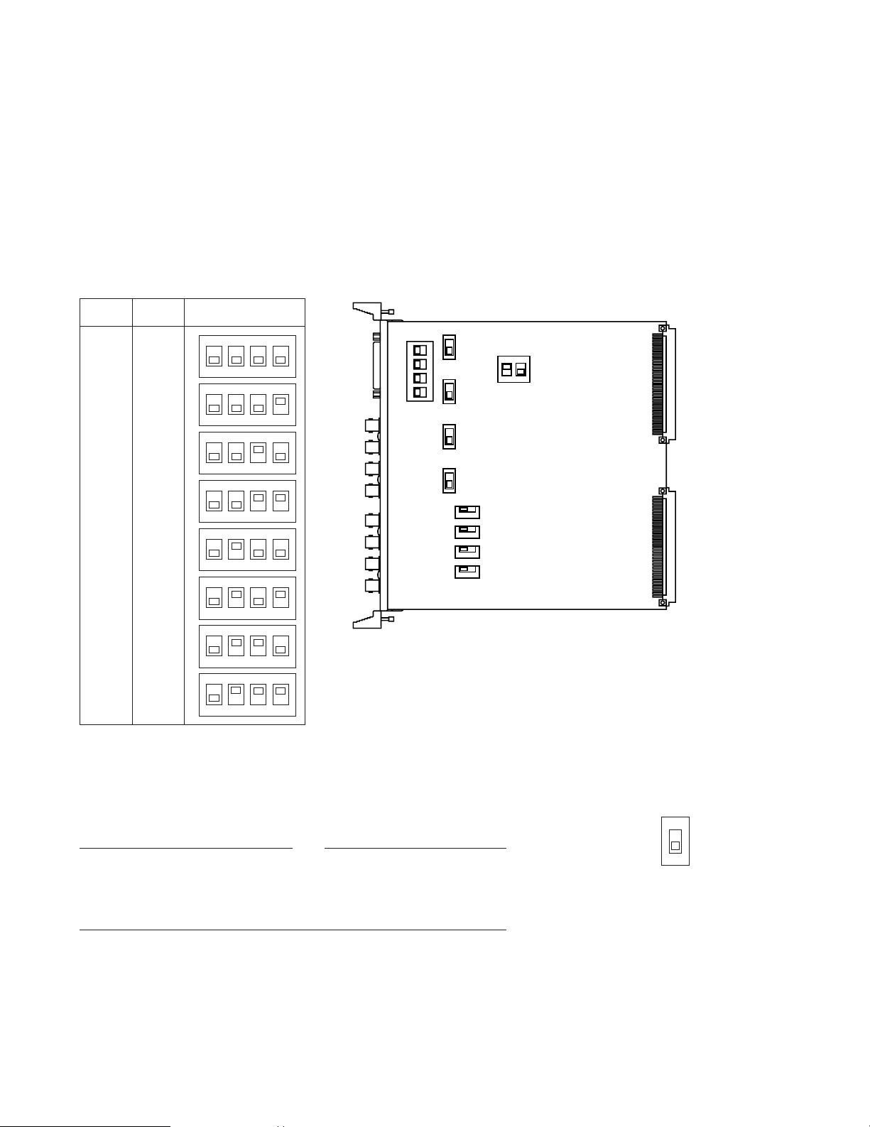
Be careful when setting these switches as the swtches are not physically
located on the board in numerical order. Switch location from the top of the
board, going downward, is: SW4 (reset out 3), SW5 (reset out 4), SW3
(reset out 2) and SW2 (reset out 1).
-2-
BOARD SETTING
Before installing this board, the following settings should be made by qualified service personnel or system installers.
1. Set switches (SW1) on the board to meet the monitor output number as shown in the following table.
Initially, monitor 1-4 is selected at the factory.
2. Set switches (SW2/SW3/SW4/SW5) on the board to choose the alarm
reset output signal as either Open Collector (OPEN C.) or Pulse (VTR).
Open Collector (OPEN C.): 16VDC 100mA max.
Pulse (VTR): +5VDC approx. 500 msec.
Initially, VTR positions are selected at the factory.
Note
2. Monitor Input/Output Connector (MONITOR IN/OUT)
OUT: The video signal selected by the Matrix Switcher is provided at this connector for the video monitor.
IN: This connector is used for video input from a VCR or system expansion to 128 camera input.
BOARD
NO.
1234
OFF
1234
OFF
1234
OFF
1234
OFF
1234
OFF
1234
OFF
1234
OFF
1234
OFF
1
2
3
4
5
6
7
8
1-4
5-8
9-12
13-16
1-4
5-8
9-12
13-16
MONITOR
OUT NO.
SW1 SETTING
1234
OFF
SW1
SW4
SW5
SW3
SW2
12
OFF
SW6
SW100
SW150
SW200
SW250
CH1
OPEN C
VTR
 Loading...