

Page 1

Data Multiplex Board
Instructions
Model No. WV-PB4164
B
efore attempting to connect or operate this product,
please read these instructions carefully and save this manual for future use.
Warning: All work related to the installation of this product should be qualified service personnel or system installer.
Features
The Data Multiplex Board, WV-PB4164, is an optional board to be installed in the Digital Disk Recorder, WJ-RT416.
Installation of this board allows users to control 4 cameras through coaxial communication cables.
Precautions
Unplug the power cord from the WJ-RT416 before
installing the board.
This board is exclusively designed for the WJ-RT416
(sold separately).
Do not install this board in other devices or use this
board independently.
Keep unused board in an antistatic bag.
The board is shipped in an antistatic bag. Discharge
static electricity from your body by touching a metal
object such as a metal locker before opening the bag
to protect the board from static electricity.
Do not touch the parts (circuits) on the board.
The parts (circuits) on the board are vulnerable to static
electricity.
Do not touch the parts on the board directly to prevent
the board from damage caused by static electricity.
Discharge static electricity before touching the
board.
Before touching the board, discharge static electricity
from your body by touching a metal object such as a
metal locker. When handling the board, hold only the
back end part (connector side) even after discharging
static electricity.
Fix the board with the screws firmly.
Make sure that the board is firmly fixed in Network Disk
Recorder by tightening the fixing screws.
If the board is not fixed firmly, it may damage both the
board and the Digital Disk Recorder.
Handle with care.
Do not strike or shake the board, as this may cause
damage.
Contact a dealer when having a problem.
Turn off the power of the Digital Disk Recorder immediately and unplug the power plug from the AC outlet,
and then contact qualified service personnel.
Page 2

Limitation of Liability
THIS PUBLICATION IS PROVIDED "AS IS" WITHOUT WARRANTY OF ANY KIND, EITHER EXPRESS OR IMPLIED,
INCLUDING BUT NOT LIMITED TO, THE IMPLIED WARRANTIES OF MERCHANTABILITY, FITNESS FOR ANY PARTICULAR PURPOSE, OR NON-INFRINGEMENT OF THE THIRD PARTY’S RIGHT.
THIS PUBLICATION COULD INCLUDE TECHNICAL INACCURACIES OR TYPOGRAPHICAL ERRORS. CHANGES
ARE ADDED TO THE INFORMATION HEREIN, AT ANY TIME, FOR THE IMPROVEMENTS OF THIS PUBLICATION
AND/OR THE CORRESPONDING PRODUCT (S).
Disclaimer of Warranty
IN NO EVENT SHALL MATSUSHITA ELECTRIC INDUSTRIAL CO., LTD. BE LIABLE TO ANY PARTY OR ANY PERSON, EXCEPT FOR REPLACEMENT OR REASONABLE MAINTENANCE OF THE PRODUCT, FOR THE CASES,
INCLUDING BUT NOT LIMITED TO BELOW:
(1) ANY DAMAGE AND LOSS, INCLUDING WITHOUT LIMITATION, DIRECT OR INDIRECT, SPECIAL, CONSE-
QUENTIAL OR EXEMPLARY, ARISING OUT OF OR RELATING TO THE PRODUCT;
(2) PERSONAL INJURY OR ANY DAMAGE CAUSED BY INAPPROPRIATE USE OR NEGLIGENT OPERATION OF
THE USER;
(3) UNAUTHORIZED DISASSEMBLE, REPAIR OR MODIFICATION OF THE PRODUCT BY THE USER;
(4) ANY PROBLEM, CONSEQUENTIAL INCONVENIENCE, OR LOSS OR DAMAGE, ARISING OUT OF THE SYSTEM
COMBINED BY THE DEVICES OF THIRD PARTY.
2
Page 3
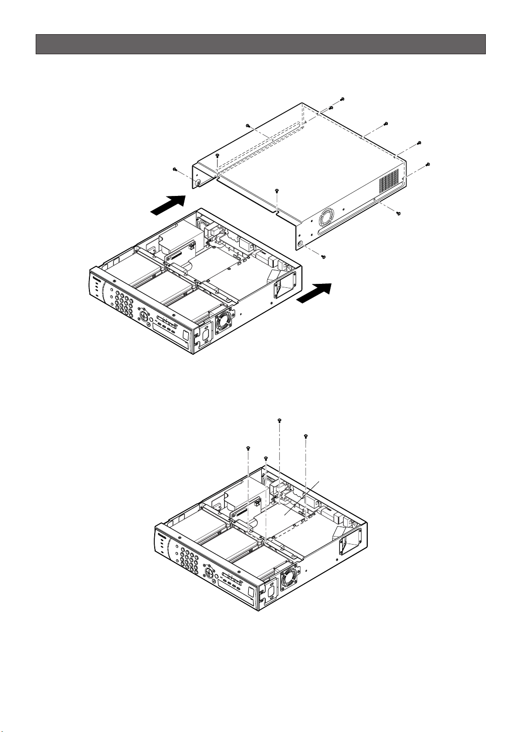
Installations
MPX board
z Remove the screws and slide the cover backward to detach the cover from the body.
x Remove the 4 screws securing the Data Multiplex Board.
3
Page 4

4-pin connector
8-pin connector
Codec boardData Multiplex board
CPU board
13-pin connector
12-pin connector
Extension Data Multiplex board (this unit)
Stud
c Connect the blue connectors of 12-pin and 13-pin cables that are supplied to the corresponding blue connectors
ON
1 2 OFF
ON
12ON12ON12
of the CODEC board below the Data Multiplex Board. Then, connect the blue connectors of 4-pin and 8-pin
cables that are supplied to the corresponding blue connectors of the CPU board.
v Set all the switches (S1 - S4) on the main board of the recorder to "OFF".
b Secure the Data Multiplex Board with the attached 4 studs using a box driver. Then, install the additional Data
Multiplex Board (this product) on the secured Data Multiplex Board with the 4 screws that were removed in the
step 2.
4
Page 5

4-pin connector
8-pin connector
13-pin connector
12-pin connector
n Connect the other side connectors of the cables that were connected in the step 3 to the corresponding connec-
tors of the additional Data Multiplex Board.
m Slide the cover back to the original position and secure the cover with the screws.
5
Page 6

Setup
• Check the menu of the WJ-RT416 to see whether the board has been successfully installed.
• Refer to the operating instructions of the Digital Disk Recorder WJ-RT416 for further information.
Specifications
Operating Temperature: From +5 °C {41 °F} to +45 °C {113 °F}
Dimensions: 170 mm (W) x 120 mm (H) x 14 mm (D)
{6-11/16" (W) x 4-3/4" (H) x 9/16" (D)}
Weight: 110 g {0.24 lbs.}
Weight and dimensions indicated are approximate.
Specifications are subject to change without notice.
Standard Accessories
Instructions (this document) ............................................ 1 pc.
13-pin connector cable .................................................... 1 pc.
12-pin connector cable .................................................... 1 pc.
8-pin connector cable ...................................................... 1 pc.
4-pin connector cable ...................................................... 1 pc.
Stud ................................................................................ 4 pcs.
6
Page 7

Information on Disposal for Users of Waste Electrical & Electronic Equipment (private households)
This symbol on the products and/or accompanying documents means that used electrical and electronic products should not be mixed with general household waste.
For proper treatment, recovery and recycling, please take these products to designated collection points,
where they will be accepted on a free of charge basis. Alternatively, in some countries you may be able to
return your products to your local retailer upon the purchase of an equivalent new product.
Disposing of this product correctly will help to save valuable resources and prevent any potential negative
effects on human health and the environment which could otherwise arise from inappropriate waste handling.
Please contact your local authority for further details of your nearest designated collection point.
Penalties may be applicable for incorrect disposal of this waste, in accordance with national legislation.
For business users in the European Union
If you wish to discard electrical and electronic equipment, please contact your dealer or supplier for further information.
Information on Disposal in other Countries outside the European Union
This symbol is only valid in the European Union.
If you wish to discard this product, please contact your local authorities or dealer and ask for the correct method of disposal.
7
Page 8

For U.S., Canadian and Puerto Rican fields:
Panasonic System Solutions Company,
Unit Company of Panasonic Corporation of North America
Security Systems
www.panasonic.com/security
For customer support, call 1.877.733.3689
Executive Office: Three Panasonic Way 2H-2, Secaucus, New Jersey 07094
Zone Office
Eastern: Three Panasonic Way, Secaucus, New Jersey 07094
Central: 1707 N. Randal Road, Elgin, IL 60123
Southern: 1225 Northbrook Parkway, Suwanee, GA 30024
Western: 6550 Katella Ave., Cypress, CA 90630
Panasonic Canada Inc.
5770 Ambler Drive,Mississauga,
Ontario, L4W 2T3 Canada (905)624-5010
http://www.panasonic.ca
Panasonic Sales Company
Division of Panasonic Puerto Rico Inc.
San Gabriel Industrial Park 65th Infantry Ave. KM. 9.5 Carolina
P.R. 00985(809)750-4300
For the other fields:
Matsushita Electric Industrial Co., Ltd.
Osaka, Japan
http://panasonic.net
© 2006 Matsushita Electric Industrial Co., Ltd. All Rights Reserved. Ns1006-1017 3TR004692BAA Printed in China
 Loading...