

Panasonic WV-NW474SE, WV-NW470S User Manual
Before attempting to connect or operate this product,
please read these instructions carefully and save this manual for future use.
Model No. WV-NW470S
WV-NW474SE
Colour CCTV Camera
Operating Instructions
中 文 FRANÇAIS DEUTSCH ENGLISHESPAÑOLITALIANO
-2-
WARNING: To prevent fire or electric shock hazard, do not expose this appliance to rain or moisture.
The apparatus shall not be exposed to dripping or splashing and that no objects filled with liquids, such as
vases, shall be placed on the apparatus.
FOR YOUR SAFETY PLEASE READ THE FOLLOWING TEXT
CAREFULLY.
WARNING
THIS APPARATUS MUST BE EARTHED
IMPORTANT
The wires in this mains lead are coloured in accordance with the following code.
Green-and-yellow: Earth
Blue: Neutral
Brown: Live
As the colours of the wire in the mains lead of this appliance
may not correspond with the coloured markings identifying the terminals in your plug, proceed as follows.
The wire which is coloured
green-and-yellow must be connect-
ed to the terminal in the plug which is marked with the letter
E or by
the earth symbol
I or coloured green or green-and-yellow.
The wire which is coloured
blue must be connected to the termi-
nal in the plug which is marked with the letter
N or coloured black.
The wire which is coloured
brown must be connected to the ter-
minal in the plug which is marked with the letter
L or coloured red.
The lightning flash with arrowhead
symbol, within an equilateral triangle,
is intended to alert the user to the
presence of uninsulated "dangerous
voltage" within the product's enclosure that may be of sufficient magnitude to constitute a risk of electric
shock to persons.
The exclamation point within an equilateral triangle is intended to alert the
user to the presence of important
operating and maintenance (servicing) instructions in the literature
accompanying the appliance.
Turn the power off at the mains to
disconnect the main power for all
unit.
CAUTION: TO REDUCE THE RISK OF ELECTRIC SHOCK,
DO NOT REMOVE COVER (OR BACK).
NO USER-SERVICEABLE PARTS INSIDE.
REFER SERVICING TO QUALIFIED SERVICE PERSONNEL.
CAUTION
RISK OF ELECTRIC SHOCK
DO NOT OPEN
CAUTION: An ALL-POLE MAINS SWITCH with a contact separation of at least 3 mm in each pole shall be incorporated
in the electrical installation of the building.
Wij verklaren als enige aansprakelijke, dat het product waarop
deze verklaring betrekking heeft, voldoet aan de volgende
normen of andere normatieve documenten, overeenkomstig de
bepalingen van Richtlijnen 73/23/EEC en 89/336/EEC.
Vi erklærer os eneansvarlige for, at dette produkt, som denne
deklaration omhandler, er i overensstemmelse med standarder
eller andre normative dokumenter i følge bestemmelserne i
direktivene 73/23/EEC og 89/336/EEC.
Vi deklarerar härmed värt fulla ansvar för att den produkt till
vilken denna deklaration hänvisar är i överensstämmelse med
standarddokument, eller andra normativa dokument som
framställs i EEC-direktiv nr. 73/23 och 89/336.
Ilmoitamme yksinomaisella vastuullamme, että tuote, jota tämä
ilmoitus koskee, noudattaa seuraavia standardeja tai muita
ohjeellisia asiakirjoja, jotka noudattavat direktiivien 73/23/EEC
ja 89/336/EE. säädöksiä.
Vi erklærer oss alene ansvarlige for at produktet som denne
erklæringen gjelder for, er i overensstemmelse med følgende
normer eller andre normgivende dokumenter som følger
bestemmelsene i direktivene 73/23/EEC og 89/336/EEC.
We declare under our sole responsibility that the product to
which this declaration relates is in conformity with the standards or other normative documents following the provisions of
Directives EEC/73/23 and EEC/89/336.
The serial number of this product may be found on the
top of the unit.
You should note the serial number of this unit in the
space provided and retain this book as a permanent
record of your purchase to aid identification in the event
of theft.
Model No.
Serial No.

-3-
CONTENTS
PREFACE .......................................................................................................................... 4
Features ......................................................................................................................... 4
System Requirements ................................................................................................... 4
Trademarks ......................................................................................................................4
Document Convention ................................................................................................... 5
PRECAUTIONS ................................................................................................................. 6
MAJOR OPERATING CONTROLS & THEIR FUNCTIONS ............................................... 7
INSTALLATION ................................................................................................................. 9
■ Installation Plans & Preparations ............................................................................... 9
■ Mounting the Camera ................................................................................................ 10
■ Connections ............................................................................................................... 11
■ Image Adjustment ..................................................................................................... 12
■ Network Connection Types ....................................................................................... 14
PREPARATIONS FOR NETWORK CONNECTIONS ......................................................... 15
■ Network Setup of Your PC ......................................................................................... 15
■ Network Setup of the Camera ................................................................................... 16
PRIOR TO CAMERA SETUP ............................................................................................. 19
■ Buttons Used for Setup ............................................................................................. 19
■ Camera Setup Menus ................................................................................................ 19
■ Setup Menu Tree ....................................................................................................... 21
SETTING PROCEDURES .................................................................................................. 22
■ Setup Selection .......................................................................................................... 22
■ Camera Setup Menu (CAM SETUP) .......................................................................... 22
■ Network Setup (NETWORK SETUP) .......................................................................... 29
INITIALIZING .................................................................................................................... 30
■ Initializing the Camera Menu ..................................................................................... 30
■ Initializing the Setup Menu ........................................................................................ 30
■ Initializing HTML Files ................................................................................................ 30
TROUBLESHOOTING ...................................................................................................... 31
PREVENTION OF BLOOMING AND SMEAR ................................................................... 32
SPECIFICATIONS ............................................................................................................. 32
STANDARD ACCESSORIES ............................................................................................. 33
OPTIONAL ACCESSORIES .............................................................................................. 33
APPENDIX ........................................................................................................................ 34
■ Optional Heater Unit WV-CW3HE .............................................................................. 34
ENGLISH

-4-
Features
• 10/100BASE-T terminal enabling you to view camera
images via the network
• User/Host authentication
• SD-II (Super Dynamic) expands the dynamic range
up to 46 dB without interference between dark and
bright portions in a scene.
• High adaptability to environmental changes
Auto light control (ALC)
B/W and colour switching (AUTO, EXT)
Electric sensitivity enhancement (SENS UP)
Electric shutter speed control
Electric zooming (EL-ZOOM)
Sync: VD2, Line-lock, Internal
White balance: AWC, ATW
• Picture quality
AGC
Digital noise reduction
Minute adjustments via SPECIAL menu
• Options
A heater unit for use in cold climates is available.
System Requirements
Your personal computer must meet the following minimum requirements to view camera pictures or to set up
parameters.
Computer: PC/AT compatible
OS: One of the following should be installed.
Microsoft Windows98 Second Edition (English version)
Microsoft Windows2000 Professional Service
Pack2 (English version)
Microsoft Windows Millennium Edition (English version)
Microsoft Windows XP (English version)
Microsoft Windows NT Workstation 4.0 Service
Pack6a (English version)
CPU: Pentium II (300 MHz) or faster
Memories: 128 MB or higher
Network Interface: 10/100 Mbps Ethernet card
Applicable Network Protocols: TCP/IP, HTTP, FTP,
SMTP, DNS, DDNS, DHCP, ARP, BOOTP, NTP
Browser: One of the following should be installed.
Internet Explorer 5.5, 5.5SP2, 6.0
Netscape Communicator 4.73, 4.78
It may happen some of the functions work wrongly
when using the Netscape Communicator version 4.73
before, or upgraded version 4.73.
Then, take the following procedures on your PC:
1. Take notes all the setting status of Netscape
Communicator in advance.
2. Uninstall the old Netscape Communicator and
delete the holder named Netscape from your PC
once.
3. Install the applicable version of Netscape
Communicator to your PC.
4. Input the same setting status that item 1 to the
Netscape Communicator.
Note: Only the English versions have been tested.
Trademarks
• Adobe, Adobe logos, and Acrobat are registered
trademarks of Adobe Systems Incorporated in the
U.S. and/ or other countries.
• Microsoft, Windows, Windows NT, and Windows XP
are registered trademarks of Microsoft Corporation
in the U.S. and/or other countries.
• Netscape, Netscape Navigator, Netscape ONE, the
Netscape N and Ship’s Wheel logos are registered
trademarks of Netscape Communications
Corporation in the U.S. and other countries. Other
Netscape product names used in this document are
also trademarks of Netscape Communications
Corporation and may be registered outside the U.S.
Panasonic introduces the WV-NW470S and WV-NW474SE colour cameras for remote video surveillance through network connections. The camera incorporates a manual pan, tilt, and azimuth table in a compact dome, besides such
essential functions as high sensitivity, wide dynamic range, video motion detection, and so forth.
PREFACE

-5-
• Ethernet is a registered trademark of Xerox
Corporation.
• Other names of companies and products contained
in these operating instructions may be trademarks
or registered trademarks of their respective owners.
• Distributing, copying, disassembling, reverse compiling, reverse engineering, and also exporting in
violation of export laws of the software provided with
this product, is expressly prohibited.
Document Convention
These operating instructions use the following conventions when describing the uses and operations.
• Windows98SE stands for Microsoft Windows98
Second Edition.
• Windows2000 stands for Microsoft Windows2000
Professional Service Pack2.
• Windows ME stands for Microsoft Windows
Millennium Edition.
• Windows NT stands for Microsoft Windows NT
Workstation 4.0 Service Pack6a.
• Windows XP stands for Microsoft Windows XP.

-6-
1. This product should be installed and connected
in conformity with local codes by qualified service personnel or system installers.
2. Use a class 2 power source supplying 24 V AC.
3. To prevent fire or electric shock hazard, use a UL
listed cable (VW-1, style 1007) to connect the
power supply to the camera.
4. Be sure to use a ceiling board/wall having
enough strength to support this camera.
5. Do not attempt to disassemble the camera.
To prevent electric shock, do not remove screws or
covers.
There are no user-serviceable parts inside.
Ask a qualified service personnel for servicing.
6. Handle the camera with care.
Do not abuse the camera. Avoid striking, shaking,
etc. The camera could be damaged by improper
handling or storage.
7. Do not use strong or abrasive detergents when
cleaning the camera body.
Use a dry cloth to clean the camera when it is dirty.
When the dirt is hard to remove, use a mild detergent and wipe gently. Care should be taken not to
scratch the dome cover when wiping it.
Wipe off any remaining detergent in it with a dry
cloth.
8. Never face the camera towards the sun.
Whether the camera is in use or not, never aim it at
the sun or other extremely bright objects. Otherwise,
blooming or smear may be caused.
9. Never aim the camera at strong light sources for
an extended period of time.
A light source such as a spot light causes burn-in on
the display screen. Failure to observe this may
cause the image to become discoloured due to
deterioration of the colour filter in the CCD.
10.Do not operate the camera beyond the specified
temperature, humidity or power source ratings.
Do not use the camera in an extreme environment
where high temperature or high humidity exists. Do
not place the camera near heat sources such as
radiators, stoves or other units that produce heat.
Use the camera under conditions where temperatures are between –10 °C and +50 °C (14 °F to
122 °F) and humidity is below 90 %.
The input power source is 24 V AC 50 Hz for WVNW474SE or 220 V - 240 V AC 50 Hz for WV-NW
470S.
11.Do not install the camera near the air outlet of an
air conditioner.
The lens may become cloudy due to condensation if
the camera is used under the following conditions.
• Rapid temperature fluctuations by switching the
air conditioner on and off.
• Rapid temperature fluctuations due to frequent
opening and closing of a door.
• Use in an environment where eyeglasses
become foggy.
• Use in a room filled with cigarette smoke or dust.
If the lens becomes cloudy due to condensation,
remove the dome cover and wipe all moist surfaces
with a soft cloth.
When installing, be sure to wipe off water drops and
splashes inside the camera. Failure to do so may
cause condensation.
12.Do not aim the camera at the same object for a
long time.
Burn-in of an image may be caused on the fluorescent screen of the CRT.
• Matsushita Electric Industrial Co., Ltd. herewith
declares that it will not be liable for any damage,
whether direct or indirect, caused by using the
product for business transactions or security, or
malfunctioning of this product.
PRECAUTIONS
-7-
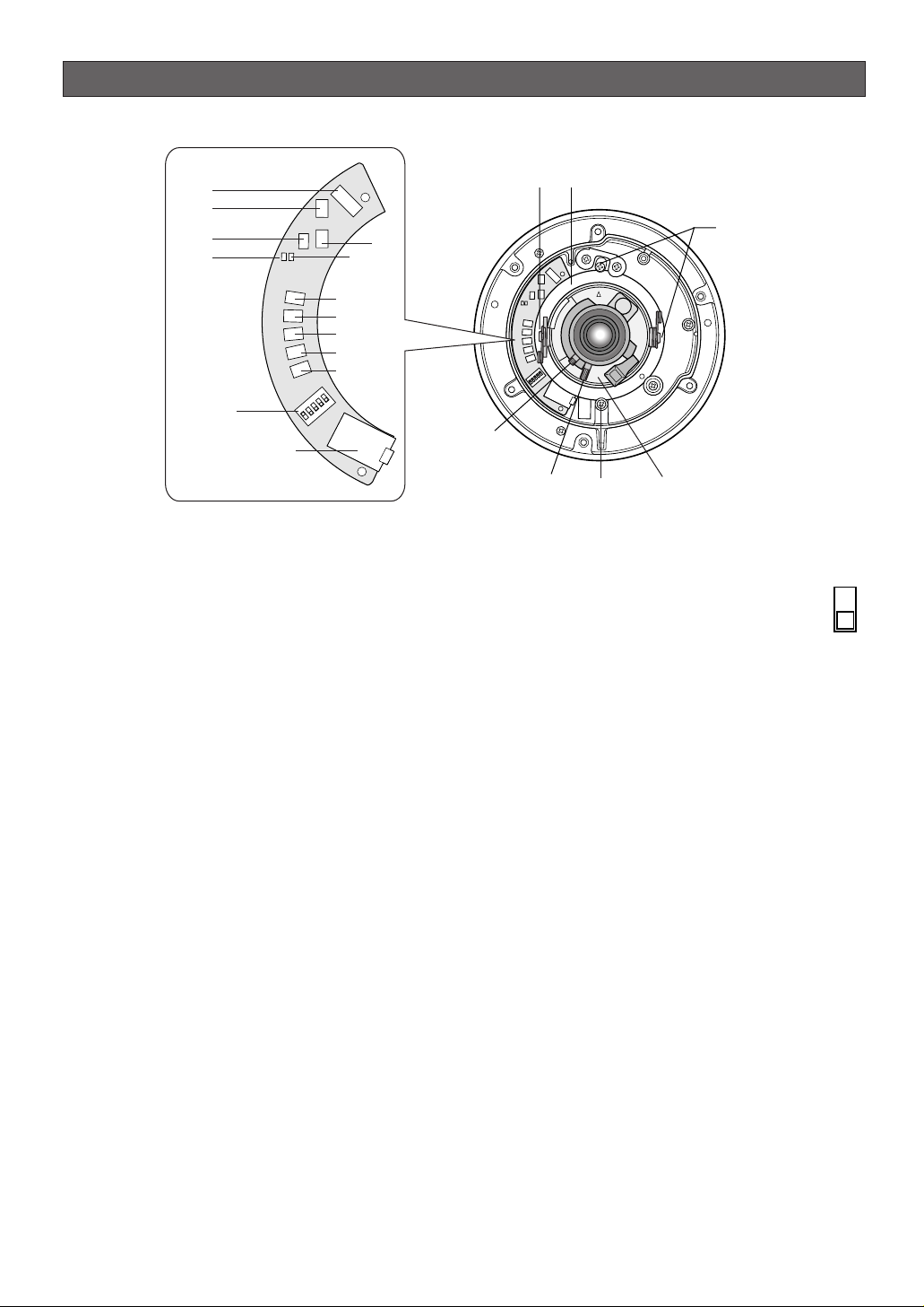
MAJOR OPERATING CONTROLS & THEIR FUNCTIONS
A
B
L
E
F
T
R
IG
H
T
U
P
D
O
W
N
SET
LINK
LED
OFF
LED
ON
RCV
A
B
L
EFT
R
IG
HT
U
P
D
O
W
N
SET
LINK
LED
OFF
LED
ON
RCV
u
i
o
!0
!1
!2
!3
!4
!5
!6
!7
!9
!8
t
r
q
y
w
Transport Protection
Screws (Red)
e
q Tilting lock screw
Fixes the tilting position.
w Panning table
Adjusts the panning angle of the camera.
e Azimuth adjuster
Adjusts the azimuth angle to level the image.
r Pan lock screw
Fixes the panning position.
t Zoom lock lever
Fixes the zoom position after adjustment.
y Focus lock lever
Fixes the focus position after adjustment.
u Optional heater connector
When an optional heater unit is installed in the camera, the harness exiting from the unit will be connected to this.
i Reset button (A)
Holding down the Up and Down buttons simultaneous for 15 seconds in the power-on state will reset
the network setup parameters.
Note: Never press both reset buttons A and B at the
same time.
o Reset button (B)
Holding down the Up and Down buttons simultaneously for 15 seconds in the power-on state will reset
the HTML files and alarm mail setup.
!0 LED switch
ON:
Enables the LINK and RCV LEDs to
indicate the communication status.
OFF: Disables the status indication.
Note: Normally set the switch to OFF. Set it
to ON only when you check the communication
status. Failure to do so may cause disturbance to
the camera image, or light leakage to the outside
of the camera in dark places.
!1 Link indicator (LINK)
Lights up when establishing communications via the
network if the LED switch is set to ON.
!2 Receive indicator (RCV)
Lights up when receiving data via the network if the
LED switch is set to ON.
!3 Left button (Left)
Moves the cursor to the left, selects the mode, and
adjusts some levels.
!4 Right button (Right)
Moves the cursor to the right, selects the mode, and
adjusts some levels.
!5 Up button (Up)
Moves the cursor upward and selects items in the
menu setup.
!6 Down button (Down)
Moves the cursor downward and selects items in the
menu setup.
ON
OFF
-8-
!7 Set button (SET)
Validates the selection or opens a detailed menu.
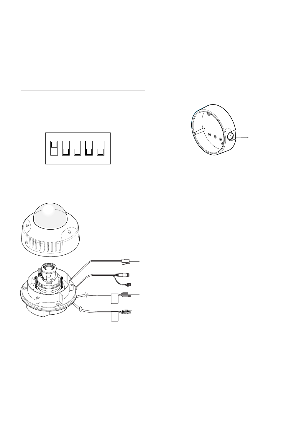
!8 DIP switch
Specifies certain settings shown in the figure. The
default setting is marked with an asterisk *.
Note: The settings will be applied to the camera
only when DIP SW, not MENU, is selected in the
menu setup.
!9 Monitor output jack
Connects to the LCD monitor and other devices with
a 3.5 diam. 2-pole L-type plug for checking images.
@0 Dome cover
@1 Network port
Connects to a PC or a network via a hub with a
10BASE-T/100BASETX cable.
@2 Video output connector
Connects to the video input terminal of the monitor
or recorder.
@3 Control connector
Connects respective devices. See Connections and
Specifications for details.
Day/night in: Optical sensor
Alarm in: Door switch
Alarm out: Buzzer
AUX out: Illumination
GND: Signal ground
@4 Power cable
Supplies power to the camera.
@5 Camera mounting bracket
@6 Cable access hole
@7 Sideway cable exit
12345
B/W B/W Aperture Upside Sync
level Down
ON High* AUTO1 Soft ON LL
OFF Low OFF* Sharp* OFF* INT*
@5
ON
12345
@0
WV-NW474SE
@6
@7
@1
@2
@3
@4
WV-NW470S
@4
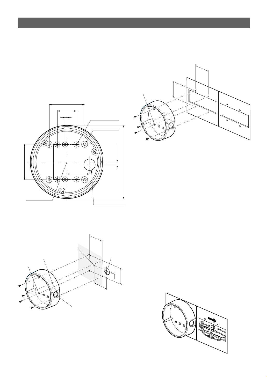
An example of flush mounting is shown. This example
shows two boxes: one is for camera mounting and the
other is for cable junction.
1. Procurement
• Four screws
Locally procure four bracket fixing screws suitable
for the installation surface and structure of the
wall/ceiling or junction box.
• Junction box
When planning to use a junction box(s), procure one
locally that meets the dimensions in the figure.
2. Installation space
Prepare a space on the surface measuring ø175 mm or
more.
3. Cable route
• When routing cables through the wall/ceiling, drill a
hole as shown in the figure.
• When routing cables sideways, open the sideway
cable exit unscrewing the lid with a hexagon
wrench.
-9-
INSTALLATION
■ Installation Plans & Preparations
The supplied camera-mounting bracket can be
installed directly on the wall/ceiling or on a procured
junction box.
On the bottom of the bracket, there are four 6.5 mm
screw holes and six 5.5 mm holes. Use the appropriate
holes matching to the installation surface.
An example of surface mounting is shown.
85 (3-3/8")
46 (1-13/16")
85 (3-3/8")
4.4 (3/16")
83.5 (3-5/16")
55 (2-3/16")
6-φ5.5 (6-φ7/32")
4-φ6.5 (6-φ1/4")
7 (9/32")
φ175 (6-7/8")
46 mm
(1-13/16")
ø5.5 mm (7/32")
Bracket fixing screw x4
(Procured locally)
83.5 mm
(3-5/16")
Bracket Center
Cable Access Hole
φ27 (1-1/16")
46 mm
(1-13/16")
Bracket center
Cable access hole
ø5.5 mm
(7/32")
55
(2-3/16")
Bracket fixing screw x4
(Procured locally)
Sideway cable exit
ø27 mm
(1-1/16")
Cable access
hole
7 mm (1/4)
83.5 mm
(3-5/16")
-10-
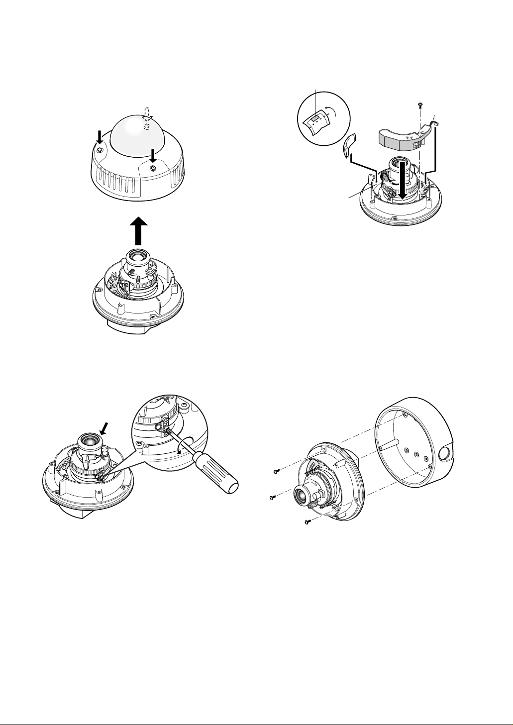
■ Mounting the Camera
Disassembling the Camera
1. Remove the dome cover by loosening the three
tamper-proof screws with the supplied bit.
2. Remove the two red-coloured screws provided for
transport protection with a Philips screwdriver.
Note: Prior to installation, discharge static electricity by
placing your hands on a metallic surface. Failure to
do so may damage the components inside the camera.
Optional Heater Unit
Assemble the optional heater unit into the camera if
necessary. Refer to APPENDIX on page 34 for details.
Mounting the Camera
1. Fix the supplied camera-mounting bracket to the
wall/ceiling or a junction box using four screws
(locally procured).
2. Perform connections referring to
■ Connections.
3. Fix the camera to the bracket with the three supplied
screws.
4. Adjust the image referring to
■ Image Adjustment.
5. A waterproof material such as silicone clay (rubber)
or the like should be applied to the screws, screw
holes, and other relevant portions if necessary.
Adhesive tape
Fold
Point "A" (wall)
Supplied screw
Harness
Another red screw
Camera mounting screw x3
(Supplied)
Copper wire size
(AWG)
Green/Yellow GND
220 V - 240 V AC Type
•Cable length and wire gauge 24 V AC Type
The recommended cable length and thickness are
shown in the table for reference. The voltage supplied to the power terminals of the camera should
be between
19.5 V AC and 28 V AC.
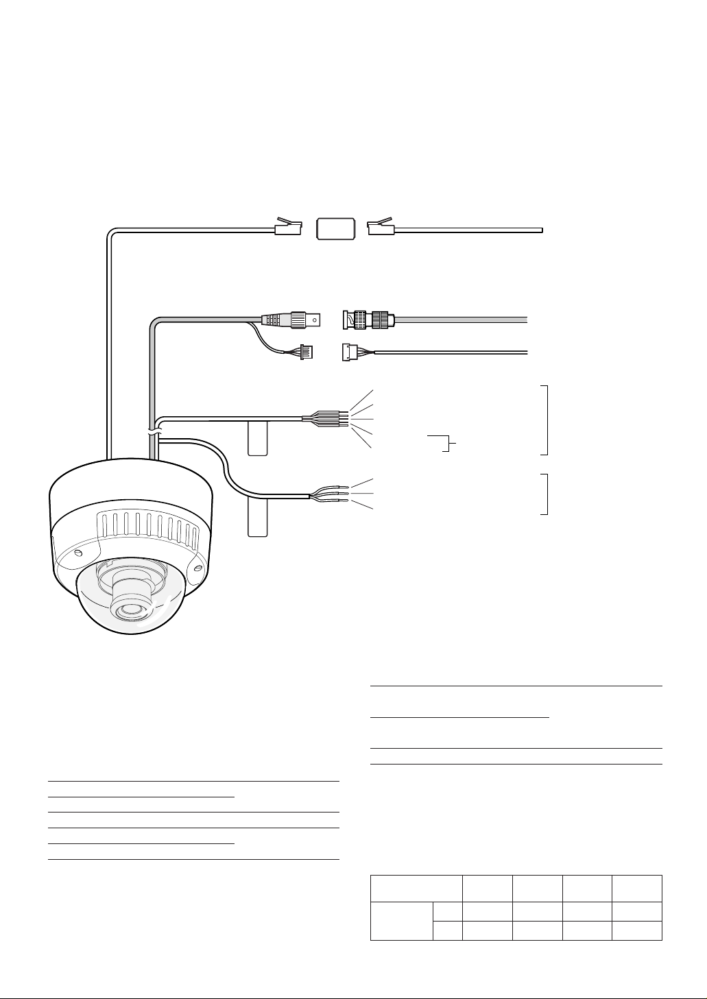
● Power Connection
Use individual power sources for the camera and
optional heater unit.
•Wire colours & functions
24 V AC Type
-11-
■ Connections
Cautions:
• This product should be installed and connected in conformity with local codes by qualified service personnel or
system installers.
• See page 2 for mains lead connection.
• Do not use a transformer with a capacity of more than 20 V A.
• Use a class 2 power supply.
• To prevent fire or electric shock hazard, use a UL listed cable (VW-1, style 1007) for 24 V AC connections.
• Be sure to connect the GND (grounding) lead of the camera and grounding terminal of the power supply.
Black (Live)
Blue (Neutral)
Green/Yellow (GND)
Green/Yellow (GND)
Brown (Live)
Blue (Neutral)
Brown (Live)
For optional heater
WV-NW474SE
WV-NW470S
Grey (Neutral)
BNCBNC
Video output
Control cable
Network
Power 24 V AC
Power 220 V - 240 V AC
Adapter (supplied)
Adapter
(supplied)
To peripherals
To Video IN (CAMERA IN)
To network
Wire colour
Grey
Brown
Blue
Green/Yellow
Black
Function
24 V AC Live
24 V AC Neutral
GND
24 V AC Live
24 V AC Neutral
Note
For camera
8.6 W
For optional heater
12.1 W
#24
(0.22mm
2
)
Length
of cable
(approx.)
(m)
(ft)
#22
(0.33mm
2
)
#20
(0.52mm2)
#18
(0.83mm2)
20 30 45 75
65 100 160 260
Wire colour
Brown
Blue
Function
220 V - 240 V AC
Live
220 V - 240 V AC
Neutral
Note
9.9 W (camera)
18.9 W (with heater)
 Loading...