

Page 1

Color CCTV Camera
Operating Instructions
Model No. WV-CW974
Before attempting to connect or operate this product,
please read these instructions carefully and save this manual for future use.
FRANÇAIS ENGLISH
Page 2
ENGLISH VERSION
CAUTION
RISK OF ELECTRIC SHOCK
DO NOT OPEN
CAUTION: TO REDUCE THE RISK OF ELECTRIC SHOCK,
DO NOT REMOVE COVER (OR BACK).
NO USER-SERVICEABLE PARTS INSIDE.
REFER SERVICING TO QUALIFIED SERVICE PERSONNEL.
NOTE: This equipment has been tested and found to comply
with the limits for a Class A digital device, pursuant to Part
15 of the FCC Rules. These limits are designed to provide
reasonable protection against harmful interference when the
equipment is operated in a commercial environment. This
equipment generates, uses, and can radiate radio frequency
energy and, if not installed and used in accordance with the
instruction manual, may cause harmful interference to radio
communications.
Operation of this equipment in a residential area is likely to
cause harmful interference in which case the user will be
required to correct the interference at his own expense.
FCC Caution: To assure continued compliance, (example use only shielded interface cables when connecting to
computer or peripheral devices). Any changes or modifications not expressly approved by the party responsible for
compliance could void the user’s authority to operate this
equipment.
The lightning flash with arrowhead
symbol, within an equilateral triangle, is
intended to alert the user to the
presence of uninsulated "dangerous
This Class A digital apparatus complies with Canadian
ICES-003.
voltage" within the product's enclosure
that may be of sufficient magnitude to
SA 1965
constitute a risk of electric shock to
persons.
The exclamation point within an
equilateral triangle is intended to alert
the user to the presence of important
operating and maintenance (servicing)
instructions in the literature accompanying the appliance.
SA 1966
WARNING:
• This apparatus must be earthed.
• All work related to the installation of this apparatus should be made qualified service personnel or system installers.
• The connections should comply with local electrical code.
The serial number of this product may be found on the top
of the unit.
You should note the serial number of this unit in the space
provided and retain this book as a permanent record of your
purchase to aid identification in the event of theft.
Model No. WV-CW964
Serial No.
-2-
For Canada
Page 3

Important safety instructions
1) Read these instructions.
2) Keep these instructions.
3) Heed all warnings.
4) Follow all instructions.
5) Clean only with dry cloth.
6) Do not block any ventilation openings. Install in accordance with the manufacturer's instructions.
7) Do not install near any heat sources such as radiators, heat registers, stoves, or other apparatus (including
amplifiers) that produce heat.
8) Do not defeat the safety purpose of the polarized or grounding-type plug. A polarized plug has two blades with
one wider than the other. A grounding type plug has two blades and a third grounding prong. The wide blade or
the third prong are provided for your safety. If the provided plug does not fit into your outlet, consult an
electrician for replacement of the obsolete outlet.
9) Protect the power cord from being walked on or pinched particularly at plugs, convenience receptacles, and the
point where they exit from the apparatus.
10) Only use attachments/accessories specified by the manufacturer.
11) Use only with the cart, stand, tripod, bracket, or table specified by the manufacturer, or sold with the apparatus.
When a cart is used, use caution when moving the cart/apparatus combination to avoid injury from tip-over.
ENGLISH
S3125A
12) Unplug this apparatus during lightning storms or when unused for long periods of time.
13) Refer all servicing to qualified service personnel. Servicing is required when the apparatus has been damaged
in any way, such as power-supply cord or plug is damaged, liquid has been spilled or objects fallen into the
apparatus, the apparatus has been exposed to rain or moisture, does not operate normally, or has been
dropped.
-3-
Page 4

Limitation of liability
THIS PUBLICATION IS PROVIDED “AS IS” WITHOUT
WARRANTY OF ANY KIND, EITHER EXPRESS OR
IMPLIED, INCLUDING BUT NOT LIMITED TO, THE
IMPLIED WARRANTIES OF MERCHANTABILITY,
FITNESS FOR ANY PARTICULAR PURPOSE, OR NONINFRINGEMENT OF THE THIRD PARTY'S RIGHT.
Disclaimer of warranty
IN NO EVENT SHALL MATSUSHITA ELECTRIC
INDUSTRIAL CO., LTD. BE LIABLE TO ANY PARTY OR
ANY PERSON, EXCEPT FOR REPLACEMENT OR
REASONABLE MAINTENANCE OF THE PRODUCT,
FOR THE CASES, INCLUDING BUT NOT LIMITED TO
BELOW:
(1) ANY DAMAGE AND LOSS, INCLUDING WITH-
OUT LIMITATION, DIRECT OR INDIRECT, SPECIAL, CONSEQUENTIAL OR EXEMPLARY,
ARISING OUT OF OR RELATING TO THE
PRODUCT;
(2) PERSONAL INJURY OR ANY DAMAGE
CAUSED BY INAPPROPRIATE USE OR NEGLIGENT OPERATION OF THE USER;
(3) UNAUTHORIZED DISASSEMBLE, REPAIR OR
MODIFICATION OF THE PRODUCT BY THE
USER;
THIS PUBLICATION COULD INCLUDE TECHNICAL
INACCURACIES OR TYPOGRAPHICAL ERRORS.
CHANGES ARE ADDED TO THE INFORMATION
HEREIN, AT ANY TIME, FOR THE IMPROVEMENTS OF
THIS PUBLICATION AND/OR THE CORRESPONDING
PRODUCT(S).
(4) INCONVENIENCE, LOSS OR DAMAGES ARISING
IF IMAGES CANNOT BE DISPLAYED, DETECTED
OR AUTOMATICALLY DETECTED FOR ANY
REASON OR CAUSE INCLUDING ANY FAILURE
OR PROBLEM OF THE PRODUCT.
(5) ANY PROBLEM, CONSEQUENTIAL INCONVE-
NIENCE, OR LOSS OR DAMAGE, ARISING OUT
OF THE SYSTEM COMBINED BY THE DEVICES
OF THIRD PARTY.
(6) ANY CLAIM OR ACTION FOR DAMAGES,
BROUGHT BY ANY PERSON OR ORGANIZATION BEING PHOTOGENIC SUBJECT, DUE TO
VIOLATION OF PRIVACY WITH THE RESULT OF
THAT SURVEILLANCE-CAMERA's PICTURE,
INCLUDING SAVED DATA, FOR SOME REASON, BECOMES PUBLIC OR IS USED FOR THE
PURPOSE OTHER THAN SURVEILLANCE.
-4-
Page 5
Features
This Color CCTV Camera is a video surveillance device
that incorporates a 1/4-type {1/4"} CCD, a 30x zoom
lens, preset and pan and tilt capabilities in a dome
configuration.
■ Super Dynamic 33(SUPER-D 33)
SUPER-D 3 can capture clear images of subjects
whose illumination is extremely different (page 28).
■ Built-in Automatic Tracking Function
A pan, tilt, and zoom-linked automatic tracking function
ensures smooth auto tracking operations.
A mask feature helps to reduce the chance of error by
letting you mask specific parts of the image from the
detection area.
■ New DSP for High Sensitivity
A new noise reduction system lowers minimum
illuminance to 0.5 lux{fc} in the color mode and 0.04
lux{fc} in the black and white mode.
■ Auto Night time Switching to Black
and White Mode
The camera can be configured to switch to the black
and white mode automatically under low light conditions for clear images, even at night.
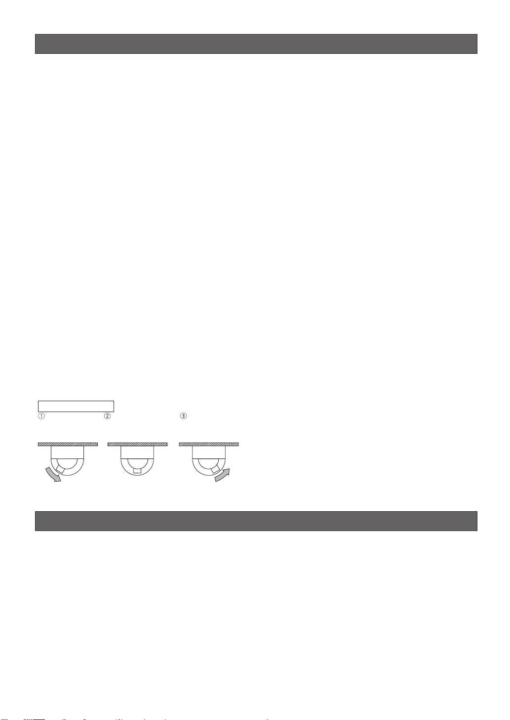
■ Digital Flip
Normally, a camera needs to stop when it points
straight down during a tilt operation. With digital flip,
however, the camera is able to tilt from 0° to 180° in a
single motion. This makes it possible to track subjects
passing directly under the camera more smoothly.
Digital Flip Operation
Tilting
downwards
· · · Digital flip is performed only when the system controller joystick is held downwards.
The picture is flipped
when the camera is
pointing straight down
(at around 135°).
Tilting upwards.
■ Privacy Zone Function
The privacy zone function can mask specific areas of
the scene from view.
■ Patrol Function
The patrol function can store manual camera movement routines for automatic playback. For example,
you can set the camera the movements of the people
to be monitored, by replaying the stored parameters
complicated move-ments are done automatically.
■ Camera Position Memory
The system can be configured with up to 256 camera
positions. A particular camera position can be selected
and viewed by entering the applicable preset number
on the system controller 10-key pad.
■ Motion Detection
The system can be configured so any motion on the
monitor screen during surveillance causes output of an
alarm signal.
This function can be used to structure a system with a
VCR that records images of nighttime intruders.
■ Internal Heating Fan
Prevents snow and frost from building up on the dome
1
cover.*
■ Waterproofing Specifications
Outdoor enclosure based on IP66*2of IEC60529
standard.
*1 Does not operate in environments with ambient
temperatures under -40 °C {-40 °F}. In environments
over -40 °C {-40 °F} defrosting may not function if
wind and snow are too strong. Use it with the power
on continuously to keep the temperature inside the
camera over -10 °C {14 °F}.
*2 Waterproof structure resistant to powerful jetting as
classified by the International Protection code.
Standard accesories
Operating Instructions (this manual) . . . . . . . . . .1 pc.
Warranty Card . . . . . . . . . . . . . . . . . . . . . . . . . . . .1 pc.
The following items are for installation.
8P Alarm Cable . . . . . . . . . . . . . . . . . . . . . . . . . . .1 pc.
4P Alarm Cable . . . . . . . . . . . . . . . . . . . . . . . . . . .1 pc.
Connector for 24 V AC . . . . . . . . . . . . . . . . . . . . .1 pc.
Front/rear sun shield . . . . . . . . . . . . . . . . . . . . . . .1 set
Front/rear sun shield mounting screws . . . . . . . .
. . . . . . . . . . . .2 pcs. (*one screw is a spare)
Waterproof cap . . . . . . . . . . . . . . . . . . . . . . . . . .3 pcs.
-5-
Page 6
About the Auto-Tracking Function
The camera's auto tracking function operates by using
image recognition. The client is responsible for
understanding and applying the following warnings
regarding installation and operation necessary to
prevent losses due to malfunction or lack of detection
as a result of unforeseeable aspects of the installation
area.
• The camera's tracking function is for monitoring
unknown intruders. It is not suitable for locations
with large numbers of people such as intersections
or retail stores. Be sure to confirm this before
installing the camera.
• Be sure to set the height of the camera under the
detailed settings (page 41) of the auto-tracking
function.
• Install the camera in a horizontal configuration, with
the dome pointed downwards.
• Install the camera securely so that it does not sway.
High resolution operation may reduce performance.
• The camera cannot track well horizontally or directly
below itself, so avoid this type of installation.
• Install the camera and adjust the view angle so that
people do not move vertically on the screen.
Vertical motion creates only small deviation on the
screen and may not be detected.
• Dirt or scratches on the dome cover make it difficult
to see the image which may reduce performance.
Periodically clean the dome cover.
• Rain or snow on the dome cover may reduce
performance. Consider placing the camera under
eaves or some kind of cover.
• Use the electronic sensitivity enhancement (page 29)
if using the camera at night (approximately 10 lx).
• Use the detection area mask (page 42) to avoid
detection errors caused by the motion of trees or
traffic.
• Auto-tracking may start for vehicles or other nonhuman movements, however, this is not a
malfunction. Adjust the view angle or use detection
area masking (page 42).
• Adjust the view angle or use detection area
masking (page 42) if there is strong back lighting,
neon lighting or other flashing lights, or reflection on
glass or the surface of a road in the image.
• To detect people, adjust the view angle so that the
people are about 1/5 of the vertical height of the
screen.
• Periodically replace consumable parts (page 7).
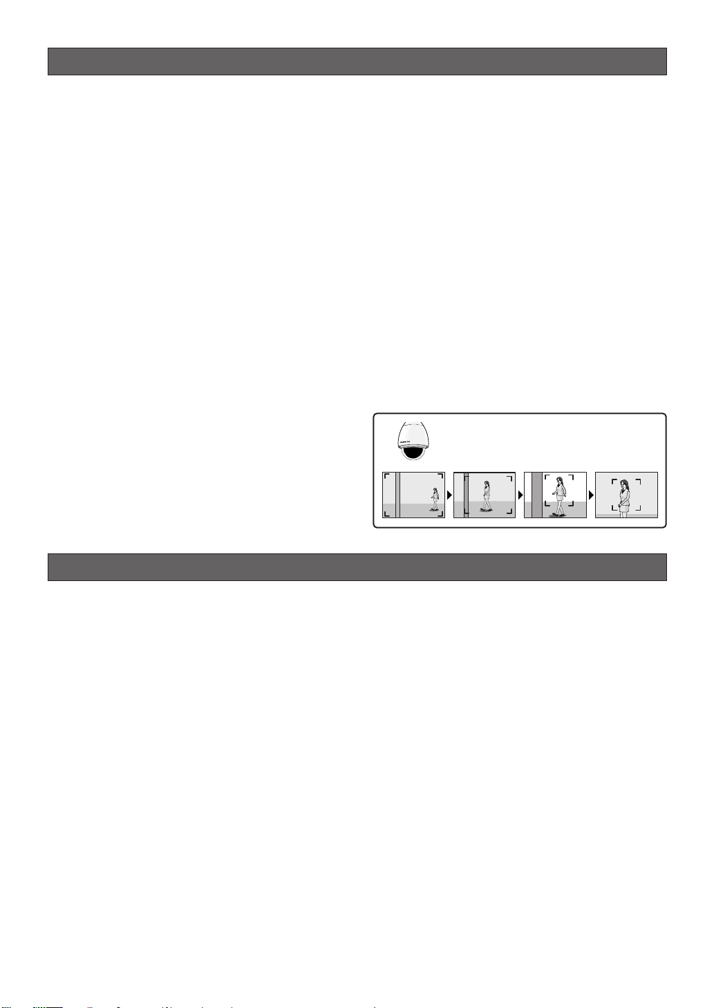
The pan, tilt and zoom functions operate in
unison to track moving subjects smoothly.
Precautions
1. Do not attempt to disassemble the camera.
To prevent electric shock, do not remove screws or
covers.
There are no user-serviceable parts inside.
Ask qualified service personnel for servicing.
2. Handle the camera with care.
Do not misuse the camera. Avoid striking, shaking,
etc. The camera could be damaged by improper
handling or storage.
3. Install the camera at a location that is able to
support its total weight.
Installing at a location that is not strong enough can
cause the camera to fall down or tip over. Be sure
to reinforce weak locations sufficiently before
installing the camera.
4. Use the fall-prevention wires to reduce the risk
of the camera falling down.
Do not detach the fall-prevention wire securing the
camera. Otherwise the camera could fall down,
causing injury to persons and damage to the
camera.
5. Never aim the camera at the sun.
Whether or not the camera is in use , never aim it at
the sun or other extremely bright objects.
Otherwise, blooming or smear may be caused.
6. Never aim the camera at strong light sources for
an extended period of time.
A light source such as a spot light causes burn-in
on the display screen. Failure to observe this may
cause the image to become discolored due to
deterioration of the color filter in the CCD.
7. Do not operate the camera beyond the specified
temperature, humidity or power source ratings.
Do not use the camera in an extreme environment
where high temperature or high humidity exists. Do
not place the camera near heat sources such as
radiators, stoves or other units that produce heat.
Use the camera under conditions where temperature is between –40 °C to +50 °C {–40 °F to 122 °F}
and humidity is below 90 %.
The input power source is 24 V AC 60 Hz.
-6-
Page 7

8. Do not install the camera near the air outlet of an
air conditioner.
The lens may become cloudy due to condensation
if the camera is used under the following
conditions.
• Rapid temperature fluctuations by switching the air
conditioner on and off.
• Rapid temperature fluctuations due to frequent door
opening and closing.
• Use in an environment where eyeglasses become
foggy.
• Use in a room filled with cigarette smoke or dust.
If the lens becomes cloudy due to condensation,
remove the dome cover and wipe all moist surfaces
with a soft cloth.
9. Consumables
Parts having contacts such as the lens-drive
motors, cooling fan motor and slip-rings inside the
camera are subject to wear with time. Please ask
the nearest service center about replacement and
maintenance of such parts.
10.Do not aim the camera at the same object for a
long time.
Burn-in of an image may be caused on the
fluorescent screen of CRT.
11.Self-diagnosis Function
If the camera continues operating abnormally for 30
seconds or more due to such an accident as
external noise, the camera will automatically reset
its power. In the case it happens frequently, check
if there would be any environmental cause.
* Matsushita Electric Industrial Co., Ltd. herewith
declares that it will not be liable for any damage,
whether direct or indirect, caused by using the
product for business transaction or security, or
malfunctioning of this product.
■ Operating precautions
■ What to do if OVER HEAT appears on the display.
This message indicates that the inside of the camera
has become extremely hot.
Immediately turn off the camera and contact your
retailer.
■ What to do if WARM UP-PLEASE WAIT.** appears
on the display.
This message indicates that the inside of the camera is
cold.
Please wait for a short time until the heating fan warms
up the inside of the camera.
The countdown shown as the numbers in “**” in quotes
is a guideline of the time required. When the value
reaches “0” the inside of the camera is warm and the
on-screen display disappears. The camera is then
reset and operation is normal.
■ Note the following to ensure long-term troublefree operation
Long operation under high temperatures and high
humidity can cause components to deteriorate and
shorten camera life.
Make sure the camera is installed in a location where it
is not directly exposed to heat from a radiator, heater,
etc.
■ About the Camera Cleaning Function
Prolonged use can lead to noise on the monitor and
divergence of preset positions.
If such conditions persist even after you perform
camera cleaning (page 40), use the special setup
menu to execute the “REFRESH” operation (page 48).
■ Do not allow anything to forcefully hit the dome
cover
Anything hitting the dome cover may damage the
camera or cause leaks.
■ CCD color filter burn-in
Intense light concentrated on one spot for a long
period can cause deterioration of the CCD internal
color filters, and discoloration of the affected part. Even
if the camera position is changed from a fixed position,
the discoloration at the previous location of the
concentrated light will remain on the screen.
■ Do not point the camera at a strong light source.
Intense light such as that produced by a spotlight
concentrated on one part of the screen can cause
blooming (rainbow around the strong light) or smearing
(vertical stripes above and below the strong light).
Bright Subject
Smearing
Blooming
■ Pictures directly below the camera
A circular object appears in the center of the picture, it
is caused by the shape of the dome cover and is not a
malfunction.
■ Do not aim the camera at the same object for a
long time.
Burn-in of an image may be caused on the fluorescent
screen of CRT.
■ Handle the camera carefully.
Do not drop the camera, or subject it to strong impact
or vibration. Such conditions create the risk of
malfunction.
-7-
Page 8

■ Consumables
Parts having contacts such as the lens-drive motors,
cooling fan motor and slip-rings inside the camera are
subject to wear with time. Contact the nearest service
dealer about replacement and maintenance of such
parts.
■ Cleaning the camera
Turn off the camera and wipe it with a soft cloth. If the
camera is very dirty, wipe it off gently with a soft cloth
moistened with a weak solution of water and a neutral
kitchen detergent. Wring all excess liquid from the
cloth before wiping the camera. Next, wipe off all
remaining solution with a soft, dry cloth.
Contact a qualified service person before cleaning the
lenses. (Lenses do not move during cleaning.)
A dirty dome cover or lens causes deterioration of
picture quality. Use lens cleaning paper (like the type
available for cleaning eyeglasses or a camera lens) to
clean the lens.
The dome cover is particularly susceptible to damage.
Gently wipe it with a soft cloth.
■ Downloading (saving) or uploading (recovering)
camera setting information
Camera setting information that can be downloaded to
the system controller etc, includes existing preset
position settings and menu settings. However, the
following items are not included.
• Patrol function (page 37)
• Area title function (page 39)
• Blemish compensation pattern (page 47)
• RS485 settings (page 20)
• Password settings (page 50)
Be sure the camera is not moving and aimed at
something that moves very little (like a wall) before
downloading camera preset data to the system
controller etc. or uploading downloaded data to the
camera.
Uploading of WV-CW974 preset data to other models
(e.g. WV-CW864, WV-CW864A) may cause an error
and failure of the uploading process.
■ Self-diagnosing Function
If abnormal operation due to external noise or some
other reason continues for more than 30 seconds, the
camera will automatically reset itself and restore
normal operation. Reset operation the same
initialization routine that is performed when the camera
is turned on. If the reset is required too often, it could
mean that the camera is installed in a location where
there is a large amount of external noise. This can
cause malfunction of the camera, so you should
contact a qualified service person or system installer
as soon as possible.
■ Combining devices
There is a limit to the number of devices that can be
put together in one configuration. Check the
specifications and outer dimensions before hooking up
the devices. For more information, see the “Panasonic
CCTV System Catalogue” or consult your retailer.
■ Installation precautions
■ Be sure to perform installation work in accor-
dance with proper technical standards for electric
installation.
■ Camera Installation Location
Discuss the installation location for the camera with
your retailer, and select a wall, ceiling or other location
that is strong enough to support the installation.
■ About ceiling mounts and brackets
Bolts for mounting the ceiling mount Attachment Pipe
to a ceiling or wall are not provided.
You need to purchase them separately in accordance
with the materials and strength of the place you are
installing the camera.
• Check the installation surface, and the anchors and
bolts to be used for sufficient strength.
• Gypsum board and wood surfaces tend to be
weak, and should not be used as an installation
surface. If use of such a surface for installation is
unavoidable, be sure to take adequate measures to
reinforce the surface.
■ Tightening the Screws
• Screws should be tightened sufficiently in
accordance with the materials and structure of the
installation location.
• Do not use an impact driver to drive screws. Doing
so can damage the screws.
• Drive the screws as straight as possible. After
tightening the screws, visually inspect them to
make sure there is no unevenness and that each
screw is tight.
■ This camera is designed for use in a hanging configuration only. Using it in an upright or inclined
configuration can cause malfunction and shorten
the life of the camera.
■ Install the camera in a horizontal configuration,
with the dome pointed downwards.
■ Be sure to remove this apparatus if it is not in use.
■ Never install or use the camera in the following
locations.
• Near a swimming pool or other areas where
chemicals are used
• Food preparation areas and other locations where
there are large amounts of steam vapor and oil, in
flammable atmospheres, other special environments
• Areas where radiation, X-rays, strong electric
waves, or magnetism is generated
• At sea, in coastal areas, or in areas where corrosive
gas is being generated
• Areas outside of the allowable ambient operating
temperature range (-40 °C to +50 °C {-40 °F to 122
°F})
-8-
Page 9

• In a motor vehicle, on a boat, or other areas subject
to strong vibration (This camera is not designed for
use in a vehicle.)
• Near an air conditioner outlet or any areas subject to
sudden changes in temperature. (Such conditions
can cause clouding and condensation formation on
the dome cover.)
■ Remove the protective sheet from the dome cover
after the installation work is complete.
■ Wiring power to the camera
The camera does not have a power switch. During the
electrical work, configure the power supply to the
camera so it can be turned on and off.
■ Noise interference considerations
When using a power line that is greater than 120 V AC
and wiring that is longer than 1 meter, wiring should be
routed using a separate metal conduit. (The metal
conduit must be earth grounded.)
Important:
• Before setting up the camera for a configuration
where the camera's RS485 data port is used for
camera control (pan, tilt, etc.) by the system
controller, the camera's DIP switches must be
configured to specify the unit number and
communication parameters. (page 13)
If DIP switch setting is not performed, the
system controller control will not be possible
and camera setup will have to be performed
again. Be sure to check the DIP switch settings
before setting up the camera.
Note: If you need to connect a ground, be sure to do it
before you connect the main power. Also, when removing
the ground, be sure to disconnect the main power.
■ Beware of high humidity.
If the camera is installed when humidity is very high,
moisture may collect in the camera and cause the
dome to become foggy. If the dome becomes foggy,
remove it when the humidity is low and eliminate the
moisture inside the camera, and then replace the
dome. (page 6, 7)
■ About the heater
The camera comes with a built-in heater so it can be
used in cold regions. The heater automatically turns on
when the internal temperature goes below 10 °C {50
°F}. However, snow and frost that collect on the dome
cover may not melt if the temperature falls below -40
°C {-40 °F}. Care needs to be taken regarding the
ambient and internal temperature when using the
camera in cold regions.
■ About effects on image quality
The camera does not have a wiper. If the camera is
installed in the following conditions image quality may
deteriorate or the image may be invisible.
(1) In the rain
The picture may be hard to see if the wind blows
rain onto the dome cover while it is raining.
(2) In the snow
When it snows, snow may collect on the dome
cover and block some of the picture. (The amount
of snow that collects on the dome cover depends
on the quality and amount of the snow.)
(3) Effects of dust and automobile exhaust
Airborne dust and automobile exhaust, from the
location where the camera is installed, may cause
dirt to build up on the dome cover and reduce the
quality of the picture.
■ Important hints to help with the installation
• A self-cleaning function is activated (PAN/TILT/
ZOOM/FOCUS) when the camera is turned on.
• There is a limit to the number of devices that can be
put together in one configuration. Check the ratings
and outer dimensions before hooking up the
devices.
-9-
Page 10

CONTENTS
Important safety instructions . . . . . . . . . . . . . . . . . . . . . . . . . . . . . . . . . . . . . . . . . . . . . . . . . .3
Limitation of liability . . . . . . . . . . . . . . . . . . . . . . . . . . . . . . . . . . . . . . . . . . . . . . . . . . . . . . . . .4
Disclaimer of warranty . . . . . . . . . . . . . . . . . . . . . . . . . . . . . . . . . . . . . . . . . . . . . . . . . . . . . . .4
Features . . . . . . . . . . . . . . . . . . . . . . . . . . . . . . . . . . . . . . . . . . . . . . . . . . . . . . . . . . . . . . . . . .5
■ Super Dynamic 3 (SUPER-D 3) . . . . . . . . . . . . . . . . . . . . . . . . . . . . . . . . . . . . . . . . . . .5
■ Built-in Automatic Tracking Function . . . . . . . . . . . . . . . . . . . . . . . . . . . . . . . . . . . . . . . . .5
■ New DSP for High Sensitivity . . . . . . . . . . . . . . . . . . . . . . . . . . . . . . . . . . . . . . . . . . . . . .5
■ Auto Night time Switching to Black and White Mode . . . . . . . . . . . . . . . . . . . . . . . . . . . .5
■ Digital Flip . . . . . . . . . . . . . . . . . . . . . . . . . . . . . . . . . . . . . . . . . . . . . . . . . . . . . . . . . . . .5
■ Privacy Zone Function . . . . . . . . . . . . . . . . . . . . . . . . . . . . . . . . . . . . . . . . . . . . . . . . . . .5
■ Patrol Function . . . . . . . . . . . . . . . . . . . . . . . . . . . . . . . . . . . . . . . . . . . . . . . . . . . . . . . . .5
■ Camera Position Memory . . . . . . . . . . . . . . . . . . . . . . . . . . . . . . . . . . . . . . . . . . . . . . . . .5
■ Motion Detection . . . . . . . . . . . . . . . . . . . . . . . . . . . . . . . . . . . . . . . . . . . . . . . . . . . . . . .5
■ Internal Heating Fan . . . . . . . . . . . . . . . . . . . . . . . . . . . . . . . . . . . . . . . . . . . . . . . . . . . . .5
■ Waterproofing Specifications . . . . . . . . . . . . . . . . . . . . . . . . . . . . . . . . . . . . . . . . . . . . . . .5
Standard accessories . . . . . . . . . . . . . . . . . . . . . . . . . . . . . . . . . . . . . . . . . . . . . . . . . . . . . . .5
About the Auto-Tracking Function . . . . . . . . . . . . . . . . . . . . . . . . . . . . . . . . . . . . . . . . . . . . . .6
Precautions . . . . . . . . . . . . . . . . . . . . . . . . . . . . . . . . . . . . . . . . . . . . . . . . . . . . . . . . . . . . . . .6
■ Operating precautions . . . . . . . . . . . . . . . . . . . . . . . . . . . . . . . . . . . . . . . . . . . . . . . . . . . .7
■ Installation precautions . . . . . . . . . . . . . . . . . . . . . . . . . . . . . . . . . . . . . . . . . . . . . . . . . . .8
Construction . . . . . . . . . . . . . . . . . . . . . . . . . . . . . . . . . . . . . . . . . . . . . . . . . . . . . . . . . . . . .11
Dip switch settings . . . . . . . . . . . . . . . . . . . . . . . . . . . . . . . . . . . . . . . . . . . . . . . . . . . . . . . .12
■ Communication Parameters (DIP Switch 2) . . . . . . . . . . . . . . . . . . . . . . . . . . . . . . . . . .12
■ Unit Number (DIP Switch 1) . . . . . . . . . . . . . . . . . . . . . . . . . . . . . . . . . . . . . . . . . . . . . .13
■ RS485 Communication Parameters (DIP Switch 1) . . . . . . . . . . . . . . . . . . . . . . . . . . . .14
■ Procedure to setup dip switch 1 . . . . . . . . . . . . . . . . . . . . . . . . . . . . . . . . . . . . . . . . . . .14
Camera installation . . . . . . . . . . . . . . . . . . . . . . . . . . . . . . . . . . . . . . . . . . . . . . . . . . . . . . . .15
■ Mounting the Camera . . . . . . . . . . . . . . . . . . . . . . . . . . . . . . . . . . . . . . . . . . . . . . . . . . .15
■ Installing the brackets . . . . . . . . . . . . . . . . . . . . . . . . . . . . . . . . . . . . . . . . . . . . . . . . . . .17
■ Attach the brackets to the camera . . . . . . . . . . . . . . . . . . . . . . . . . . . . . . . . . . . . . . . . .17
■ Attach the front and rear sun shields (provided) to the camera . . . . . . . . . . . . . . . . . . .17
Connections . . . . . . . . . . . . . . . . . . . . . . . . . . . . . . . . . . . . . . . . . . . . . . . . . . . . . . . . . . . . . .18
RS485 setup . . . . . . . . . . . . . . . . . . . . . . . . . . . . . . . . . . . . . . . . . . . . . . . . . . . . . . . . . . . . .20
Operation Examples . . . . . . . . . . . . . . . . . . . . . . . . . . . . . . . . . . . . . . . . . . . . . . . . . . . . . . . .21
Using the setup menu . . . . . . . . . . . . . . . . . . . . . . . . . . . . . . . . . . . . . . . . . . . . . . . . . . . . . .24
■ Displaying the Setup Menu . . . . . . . . . . . . . . . . . . . . . . . . . . . . . . . . . . . . . . . . . . . . . .24
■ Camera ID Settings . . . . . . . . . . . . . . . . . . . . . . . . . . . . . . . . . . . . . . . . . . . . . . . . . . . . .24
■ Scene Select Settings . . . . . . . . . . . . . . . . . . . . . . . . . . . . . . . . . . . . . . . . . . . . . . . . . . .25
■ Preset Position Settings . . . . . . . . . . . . . . . . . . . . . . . . . . . . . . . . . . . . . . . . . . . . . . . . . .25
■ Language Setting . . . . . . . . . . . . . . . . . . . . . . . . . . . . . . . . . . . . . . . . . . . . . . . . . . . . . .27
■ Advanced Menu Settings . . . . . . . . . . . . . . . . . . . . . . . . . . . . . . . . . . . . . . . . . . . . . . . .27
Camera settings . . . . . . . . . . . . . . . . . . . . . . . . . . . . . . . . . . . . . . . . . . . . . . . . . . . . . . . . . .28
■ Using the Camera Setup Menu . . . . . . . . . . . . . . . . . . . . . . . . . . . . . . . . . . . . . . . . . . .28
Pan/Tilt settings . . . . . . . . . . . . . . . . . . . . . . . . . . . . . . . . . . . . . . . . . . . . . . . . . . . . . . . . . . .33
■ Using the Pan/Tilt Setup Menu . . . . . . . . . . . . . . . . . . . . . . . . . . . . . . . . . . . . . . . . . . . .33
Auto tracking settings . . . . . . . . . . . . . . . . . . . . . . . . . . . . . . . . . . . . . . . . . . . . . . . . . . . . . . .41
■ Using the Auto Tracking Setup Menu . . . . . . . . . . . . . . . . . . . . . . . . . . . . . . . . . . . . . .41
Alarm settings . . . . . . . . . . . . . . . . . . . . . . . . . . . . . . . . . . . . . . . . . . . . . . . . . . . . . . . . . . . .44
■ Using the Alarm Setup Menu . . . . . . . . . . . . . . . . . . . . . . . . . . . . . . . . . . . . . . . . . . . . .44
Special settings . . . . . . . . . . . . . . . . . . . . . . . . . . . . . . . . . . . . . . . . . . . . . . . . . . . . . . . . . . .47
■ Using the Special Setup Menu . . . . . . . . . . . . . . . . . . . . . . . . . . . . . . . . . . . . . . . . . . . .47
Scene select setting . . . . . . . . . . . . . . . . . . . . . . . . . . . . . . . . . . . . . . . . . . . . . . . . . . . . . . .49
■ Using the Scene Select Setting Menu . . . . . . . . . . . . . . . . . . . . . . . . . . . . . . . . . . . . . .49
Password settings . . . . . . . . . . . . . . . . . . . . . . . . . . . . . . . . . . . . . . . . . . . . . . . . . . . . . . . . .50
■ Password Lock Settings . . . . . . . . . . . . . . . . . . . . . . . . . . . . . . . . . . . . . . . . . . . . . . . . .50
Shortcuts . . . . . . . . . . . . . . . . . . . . . . . . . . . . . . . . . . . . . . . . . . . . . . . . . . . . . . . . . . . . . . . .52
Troubleshooting . . . . . . . . . . . . . . . . . . . . . . . . . . . . . . . . . . . . . . . . . . . . . . . . . . . . . . . . . . .54
Specifications . . . . . . . . . . . . . . . . . . . . . . . . . . . . . . . . . . . . . . . . . . . . . . . . . . . . . . . . . . . .59
-10-
Page 11
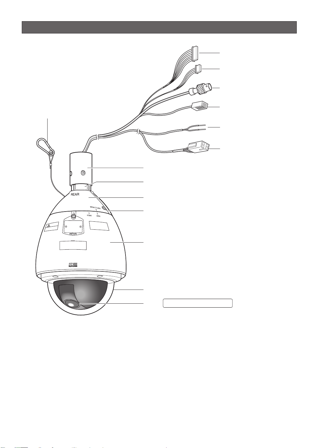
Construction
Alarm Input Connector
Alarm Output Connector
Video Output Connector
Camera Safety Wire
Data Port
Power Cord
for Heater
Power Connector
Attachment Pipe
Upper Base
Rear sun shield (provided)
Front sun shield (provided)
Sun shield (pre-attached at factory)
Dome cover (do not remove)
Lens The lens cannot replaced.
Ensuring Trouble-free Operation
• This camera uses a “slip ring” for transmission of electrical power and signals. A dirty slip ring can cause
deterioration of picture quality during panning and generation of noise.
In order to ensure trouble-free camera operation, make sure that the cleaning function (page 40) is turned on.
• If cleaning the slip ring does not eliminate poor picture quality and noise, it could mean that the slip ring has
reached the end of its service life. Contact a qualified service person or system installer to have it replaced.
-11-
Page 12
Dip switch settings
In a configuration, the camera's RS485 data port is used for camera control by the system controller, the camera's
DIP switches must be configured to specify the unit number and communication parameters.
You need to set the DIP switches before installing the camera in the ceiling or on a wall.
Important:
Do not adjust the DIP switches if you are using a coaxial multiplex system, leave them off.
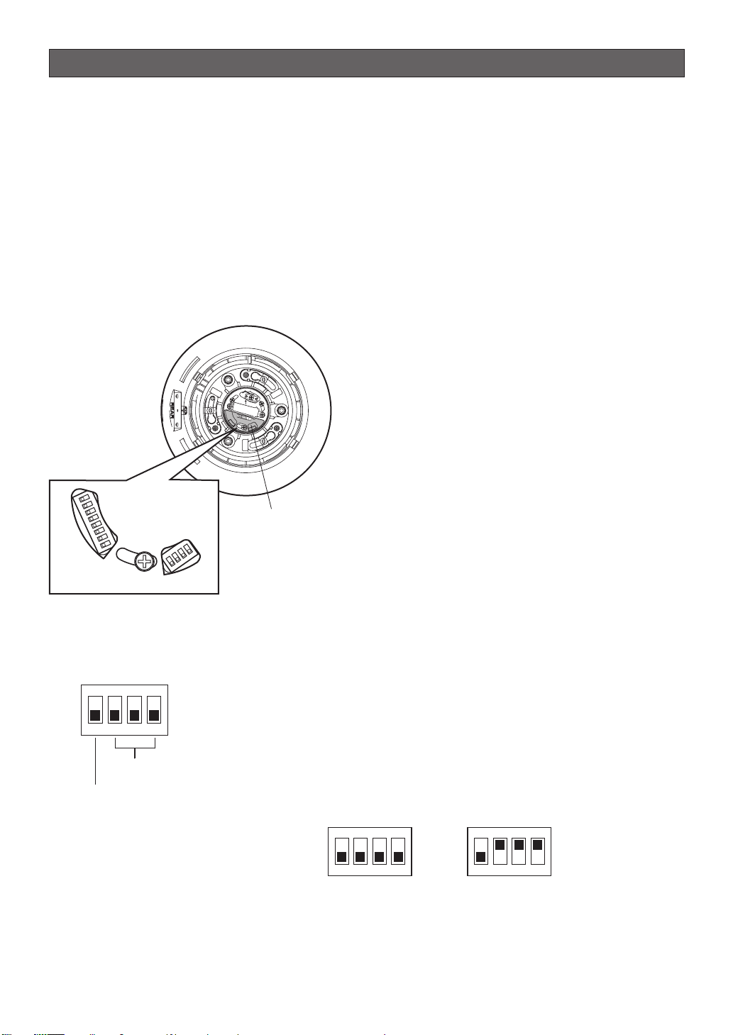
1. Attaching and removing the Upper Base
Refer to the installation manual of the mounting
brackets sold separately for installation for
removing the Upper Base.
2. Remove the protective sticker from the top of the
sun shield. (Keep the protective sticker for in step 4.)
The DIP switches can be set now.
Camera top view
START
RS485Setting
S
W
1
W2
S
O
N
1
2
3
4
DIP SW1
5
6
7
8
N
4
O
3
2
1
DIP SW2
Protective Sticker
DIP Switch
3. Set the DIP switches as the following:
Communication parameters: Set with switch 2
Unit number: Set with switch 1
4. Put the protective sticker back over the DIP
switches.
■ Communication Parameters (DIP Switch 2)
The factory default settings are all OFF.
ON
1234
Communication
Parameters
Terminator
Switch 1: Terminator (Internal Termination Resistance)
Set to ON in the following situations.
• When only one camera is connected.
• When only one camera is connected via a daisy chain over a long
distance.
Switches 2 to 4: Communication Parameters
This setting toggles between 2-line and 4-line communication. Use
these switches to select the communication protocol being used.
ON
1234
4-line Communication
-12-
ON
1234
2-line Communication
Page 13
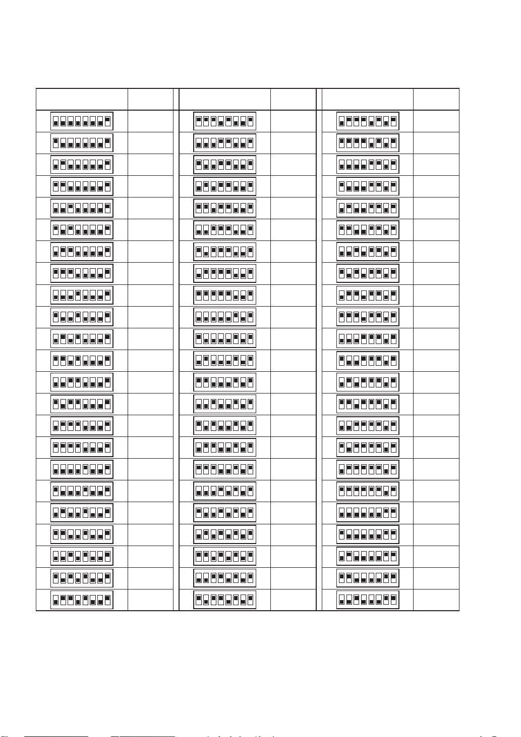
■ Unit Number (DIP Switch 1)
The factory default settings of these DIP switches are all OFF. (Coaxial Multiplex System)
Table-1
DIP Switch 1
ON
1234
1234
1234
1234
1234
1234
1234
1234
1234
1234
1234
1234
1234
1234
1234
1234
1234
1234
1234
1234
1234
1234
1234
5678
5678
5678
5678
5678
5678
5678
5678
5678
5678
5678
5678
5678
5678
5678
5678
5678
5678
5678
5678
5678
5678
5678
ON
ON
ON
ON
ON
ON
ON
ON
ON
ON
ON
ON
ON
ON
ON
ON
ON
ON
ON
ON
ON
ON
Unit
Number
1 ~ 96
(page 14 Note)
1
2
3
4
5
6
7
8
9
10
11
12
13
14
15
16
17
18
19
20
21
22
DIP Switch 1
ON
5678
1234
ON
5678
1234
ON
1234
1234
1234
1234
1234
1234
1234
1234
1234
1234
1234
1234
1234
1234
1234
1234
1234
1234
1234
1234
1234
5678
5678
5678
5678
5678
5678
5678
5678
5678
5678
5678
5678
5678
5678
5678
5678
5678
5678
5678
5678
5678
ON
ON
ON
ON
ON
ON
ON
ON
ON
ON
ON
ON
ON
ON
ON
ON
ON
ON
ON
ON
Unit
Number
23
24
25
26
27
28
29
30
31
32
33
34
35
36
37
38
39
40
41
42
43
44
45
DIP Switch 1
ON
1234
ON
1234
ON
1234
ON
1234
ON
1234
ON
1234
ON
1234
ON
1234
ON
1234
ON
1234
ON
1234
ON
1234
ON
1234
ON
1234
ON
1234
ON
1234
ON
1234
ON
1234
ON
1234
ON
1234
ON
1234
ON
1234
ON
1234
5678
5678
5678
5678
5678
5678
5678
5678
5678
5678
5678
5678
5678
5678
5678
5678
5678
5678
5678
5678
5678
5678
5678
Unit
Number
46
47
48
49
50
51
52
53
54
55
56
57
58
59
60
61
62
63
64
65
66
67
68
-13-
Page 14
DIP Switch 1
ON
1234
1234
1234
1234
1234
1234
1234
1234
1234
5678
5678
5678
5678
5678
5678
5678
5678
5678
ON
ON
ON
ON
ON
ON
ON
ON
Unit
Number
69
70
71
72
73
74
75
76
77
DIP Switch 1
ON
1234
1234
1234
1234
1234
1234
1234
1234
1234
5678
5678
5678
5678
5678
5678
5678
5678
567
ON
ON
ON
ON
ON
ON
ON
ON
8
Unit
Number
78
79
80
81
82
83
84
85
86
DIP Switch 1
ON
5678
1234
ON
5678
1234
ON
5678
1234
ON
5678
1234
ON
5678
1234
ON
1234
1234
1234
1234
5678
5678
5678
5678
ON
ON
ON
Unit
Number
87
88
89
90
91
92
93
94
95
Notes:
• When using the Unit Number “1 ~ 96” setting, the unit number setting needs to be configured using the RS485
SET UP menu. For details about configuring this setting, see step 2 on page 20.
• Turning on power when this setting is selected causes the RS485 SET UP menu to appear during the initialization
routine.
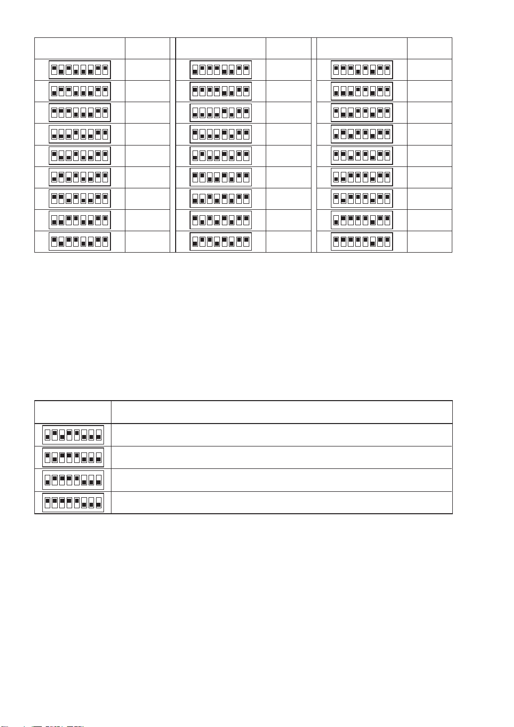
■ RS485 Communication Parameters (DIP Switch 1)
Configuring DIP Switch 1 as shown below resets communication parameters to their factory default settings. You can
then change the settings as desired.
Table-2
DIP Switch 1 Setting Description
ON
1234
ON
1234
ON
1234
ON
ON
1234
5678
5678
5678
5678
This setting resets communication parameters to the factory default settings.
BAUD RATE : 19 200 bit/s, DATA BIT : 8 bit, PARITY CHECK : NONE, STOP BIT : 1 bit
BAUD RATE : 9 600 bit/s, DATA BIT : 8 bit, PARITY CHECK : NONE, STOP BIT : 1 bit
BAUD RATE : 4 800 bit/s, DATA BIT : 8 bit, PARITY CHECK : NONE, STOP BIT : 1 bit
■ Procedure to setup dip switch 1
(1) Turn off the camera and use DIP Switch 1 to configure RS485 Communication Parameters as shown in Table-2.
(2) Turn on the camera.
This applies the setting you configured in step (1).
(3) Turn off the camera, use DIP Switch 1 to set the unit number (as shown in Table-1), and then turn the camera
back on again.
-14-
Page 15

Camera installation
■ Mounting the Camera
Ceiling mount
The figure shows an example of the camera mounted
on a ceiling with a locally procured bracket.
Refer to the instructions included with the bracket for
filling gaps and holes with waterproof material.
● Construction
40 1-1/2B deep 30 MAX
PT11 crest (taper pipe thread)
(Ø58)
2. Disassembling the Camera
(1) Remove the upper base from the camera by
loosening 3 screws. The screws that are
removed need to be used during reassembly.
Be careful to not lose them. Turn the upper base
and separate it.
* Special screw (mounting screw): Use a
hexagon wrench for the hexagon screw (M6).
x3
(2) Remove the attachment pipe from the upper
base by loosening 4 screws.
* Special screw (mounting screw): Use a
hexagon wrench for the hexagon screw (M6).
(60)
40 1-1/2A deep 30 MAX
PT11 crest (parallel pipe thread)
25
85
● Assemble procedure
1. Preparations
(1) Procure a ceiling mount bracket.
(2) To prevent the camera from falling, use a
mounting a bracket to which a safety wire can
be attached.
(3) Installation Surface
Caution: Consult an expert on the load bearing
capacity of the installation surface and
structure. If the surface is not strong enough,
the camera may fall down. Refer to the
product specifications for weights.
Prepare appropriate hardware (e.g. wall nuts,
anchor bolts, etc.) for fixing on the installation
surface.
x4
-15-
Page 16

3. Mounting the Bracket
(1) Fix the bracket to the installation surface using
appropriate bolts, nuts or the like (not supplied).
Make sure that everything is tightened securely.
Attachment Pipe
(2) Fix the attachment pipe to the bracket.
(3) Thread cables through the bracket. Connect
cables, referring to CONNECTIONS.
Warning: Seal the cables with plastic or rubber
tape to prevent it from being exposed.
Cables
Upper Base
(4) Fix the upper base to the attachment pipe.
• Fasten 4 screws (the screws that were
removed in step (2) of "2. Disassembling the
Camera") making sure that "REAR" engraved
on the upper base faces the wall.
Recommended torque: Approximately 5.0
N/m {51 kgf cm}
• Fill the gap between the bracket and
attachment pipe with waterproof material
such as silicon clay. See instructions of the
bracket for details.
Warning: Carefully apply the sealing so that
water or moisture cannot get inside. If water
gets inside the camera it could cause a
shock or fire. Also, if moisture gets inside the
camera it could cause the dome to become
foggy.
4. Mounting the camera
(1) Aim the "START" arrow at the bent portion of the
leaf spring.
Bending
(2) Be sure to hook the fall prevention wire into the
bracket.
(3) Fix the camera to the upper base.
• Move the camera up so that its guide pins fit
into the guide holes of the upper base.
• Turn the camera counter-clockwise to the
end, viewed from the bottom.
• Fasten 3 screws (the screws that were
removed in step (1) of “2. Disassembling the
Camera”).
Caution: Tighten the three (3) mounting screws
for the upper base.
Recommended torque: Approximately 5.0
N/m {51 kgf cm}
Poorly tightened screws may result in water
leaking into the camera or possible fire.
START
Leaf Spring
Fall Prevention
Wire
x3 Screws
Upper Base
Enclosure
Waterproof Material
x4 Screws
Upper Base
-16-
Page 17
■ Installing the brackets
Refer to the installation guides provided with the
brackets.
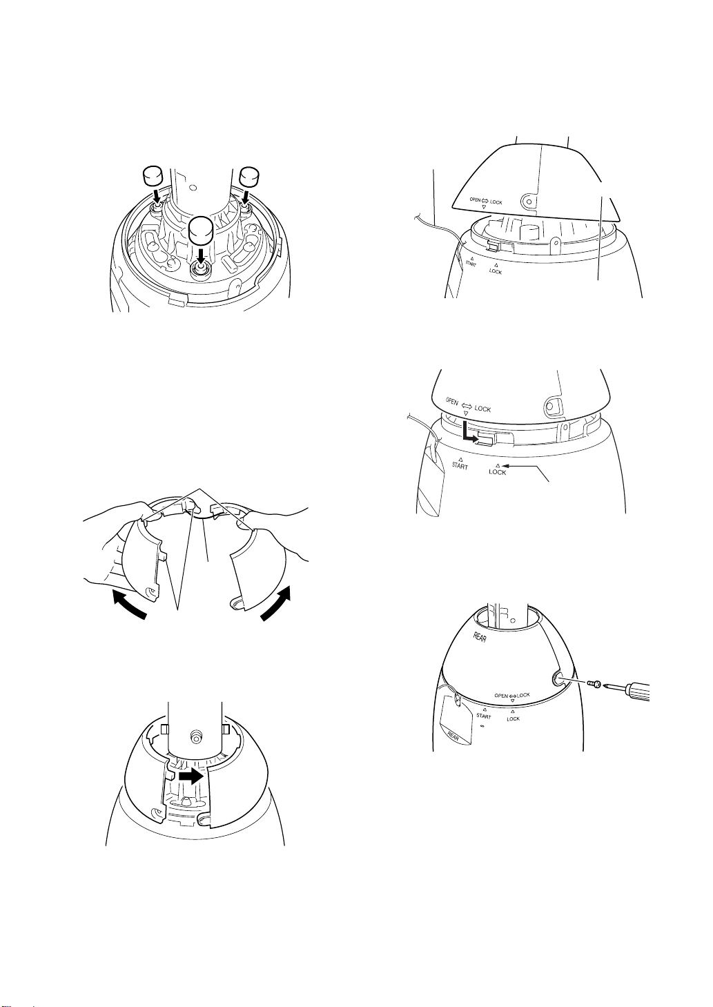
■ Attach the brackets to the camera
1. Put the waterproof caps (provided) onto the tops of
the screws.
■ Attach the front and rear sun shields (provided) to the camera
1. Hold the front and rear sun shields by the
indentations on the rims and release the hooks from
both sides to separate them.
A wire is attached to one side to prevent them from
being lost.
3. Before clamping the sun shield, close the front and
rear sun shields (first latch the hook on the wire
side, and then do the other side).
* Take care that the camera safety wire does not go
on the inside.
Camera
Safety wire
Sun shield
4. Align the arrow (▽) on the rear sun shield with the
"START" arrow (△) on the sun shield and then turn
them to the “LOCK” arrow (△) until they click.
Indented parts
Wire
Unhook
2. Hold the front and rear sun shields near the Upper
Base in position to be mounted.
Align with this arrow
5. Use the screws on the front/rear sun shields to
attach them to the camera.
Recommended tightening torque: 5.0 N/m {51 kgf
cm}
Note: To remove the front/rear sunshields from the
camera, do the above procedure in reverse.
Caution: The camera safety wire is designed to allow
the camera to hang from it. Do not apply force greater
than the weight of the camera to the wire.
-17-
Page 18

Connections
Precautions
• The following connections should be made by qualified service personnel or system installers in accordance
with all local codes.
• Turn off the power at the fuse box before starting the installation work, or it so could result in fire, electric shock,
personal injury, and material damage.
24 V AC Cable for Heater
Separate 2-wire
24 V AC Cable for camera
24 V AC
RS485 Data Port
Video Output
Connector
Alarm Input
Connector
Twisted Pair Cable*1
(RJ-12)
Coaxial Cable (5C-2V)*2
(BNC)
8P Alarm Cable (provided)
To Matrix Switcher,
etc.
To VIDEO IN port
(CAMERA IN)
To sensor, etc.
Alarm Output
Connector
RS485 Data Port
Data
Tx
Data
Rx
Red
Orange
Yellow
Green
*1: For twisted pair cable, use shielded low-impedance cable with a thickness of at least AWG#22
*2: Keep the overall length of coaxial cable under 1200 meters (in the case of 5C-2V).
*3: Be sure to connect the grounding cable to ground.
T(B)
T(A)
R(B)
R(A)
(RJ-12)
2
(0.33 mm
For details, see the operating instructions for the Panasonic system equipment you are going to
connect.
).
Alarm Input Connector
Alarm In/Out Ratings
Alarm In : 5 V DC pull-up input. Drive capacity of at
lease 0.2 mA required.
OFF : 4 V DC minimum 5 V DC maximum,
or open
ON : 1 V DC maximum or short
Alarm Out : Open collector output. 16 V DC, 100 mA
maximum drive capacity
OFF : Open
ON : 100 mA maximum
* When connecting to an external device, set up the
system so the ratings are not exceeded.
Note: Do not turn off camera power within 30 seconds
after turning it on. Doing so can cause pan, tilt, zoom,
or focus to go out of position.
4P Alarm Cable (provided)
Alarm In 1 (Black)
GND (Brown)
Alarm In 2 (Red)
GND (Orange)
Alarm In 3 (Yellow)
Light Blue or Green
GND (
Alarm In 4 (Blue)
GND (Violet)
)
• 24 V AC Power Supply Connection
Recommended wire gauge sizes for 24 V AC line
Copper wire size
(AWG)
Length
of cable
(approx.)
Accessory Connector Information
Pin no. Power source
1
2
3
4
To buzzer,
display device, etc.
Alarm Output Connector
Alarm Out 1 (Grey)
GND (White)
Alarm Out 2 (Pink)
GND (Light Green
or Light Blue)
#24
(0.22mm
20 30 45 75
(m)
65 100 160 260
(ft)
24 V AC LIVE
24 V AC NEUTRAL
Ground
Not use
2
)
(0.33mm
#22
#20
2
)
(0.52mm2)
4
2
#18
(0.83mm2)
3
1
-18-
Page 19
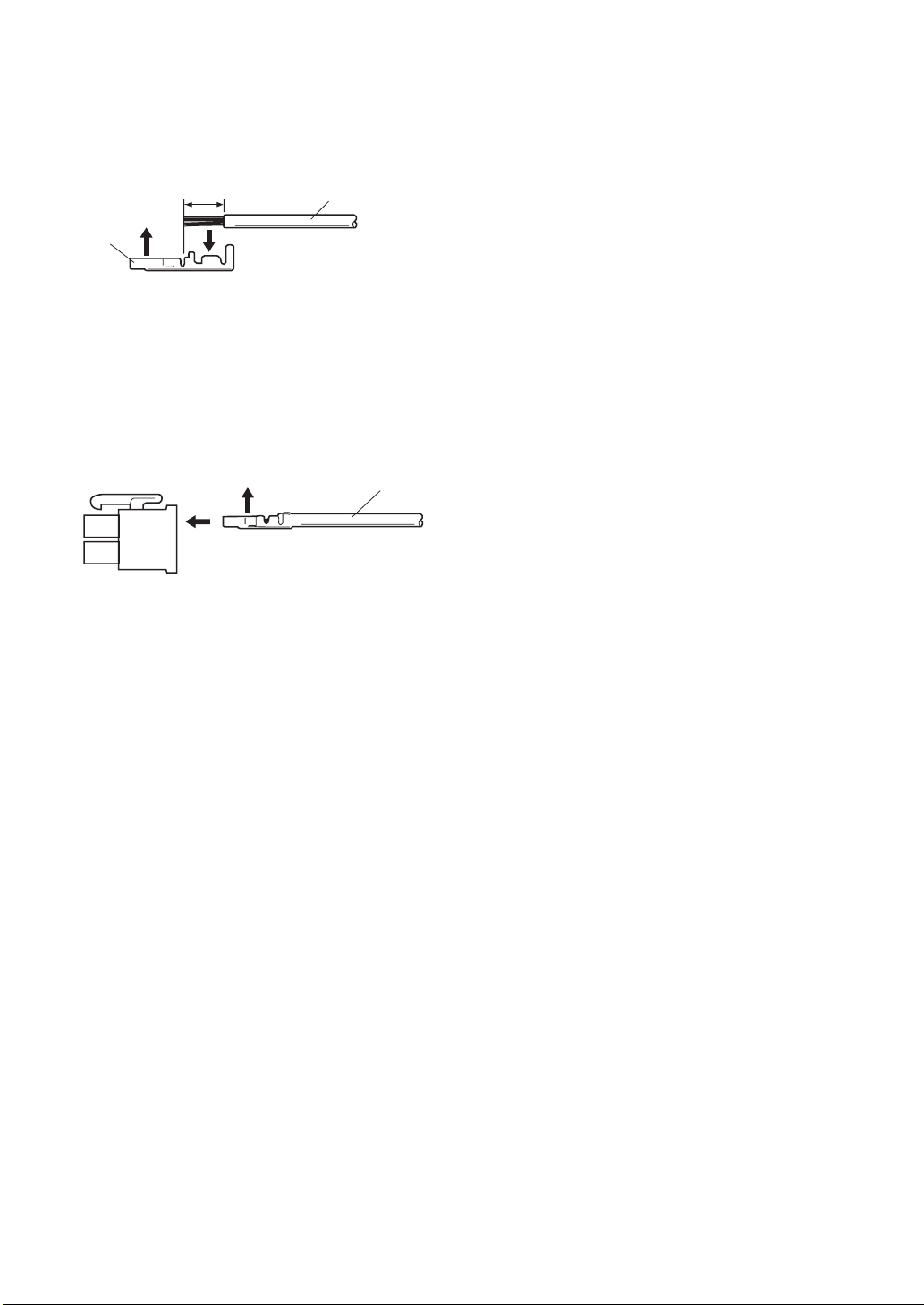
How to Assemble the Cable with the Accessory
Connector
Strip back the cable jacket approx. 3 mm {0.1"} and
separate the individual conductors.
Approx.
Approx.
3 mm {0.1"}
Contact
Contact
Up
Up
3 mm {0.1"}
A
Insert
Insert the wire until A position
Insert the wire until A position
and clamp the contacts.
and clamp the contacts.
Wire
Wire
Prepare the individual conductors for clamping. Use
MOLEX band tool part number 57027-5000 (for ULStyle Cable UL1015) or 57026-5000 (for UL-Style
UL1007) for clamping the contacts.
After clamping the contacts, push them into the proper
holes in the accessory connector of this camera until
they snap in place.
Up
Contact
Wire
Cautions:
• Shrinking the cable-entry seal is a one-time
procedure. Do not shrink the cable-entry seal until
ascertaining that the unit is functioning.
• CONNECT THIS TO 24 V AC CLASS 2 POWER
SUPPLY ONLY.
-19-
Page 20
RS485 setup
The following procedure is to configure the RS485
setup when using the system controller to control the
camera (pan, tilt, etc.) via the camera's data port.
1. Display the setup menu (page 24), move the cursor
to COMMUNICATION O, and then press the CAM
(SET) button.
This will display the RS485 setup menu.
2. Check the unit number. (page 13)
The UNIT NUMBER item shows the unit number
specified by DIP Switch 1. The factory default unit
number is 1.
If DIP Switch 1 specifies 1 to 96 as the unit number,
move the cursor to UNIT NUMBER and then tilt the
joystick left or right to select a unit number (1 to 96).
** RS485 SETUP **
UNIT NUMBER
SUB ADDRESS
BAUD RATE
DATA BIT
PARITY CHECK
STOP BIT
XON/XOFF
WAIT TIME
ALARM DATA
DELAY TIME
RET TOP
1
----19200
8
NONE
1
NOT USE
OFF
AUTO2
OFF
Note: It is not necessary to configure the RS485
SET UP menu SUB ADDRESS setting.
3. Move the cursor to BAUD RATE, and then tilt the
joystick left or right to select a baud rate setting.
Tilting the joystick cycles through the baud rate
(transmission speed) display in the sequence
shown below. (unit: bits/s) The factory default
setting is 19200.
8. Move the cursor to WAIT TIME, and then tilt the
joystick left or right to select a wait time setting.
The wait time is the time that the camera should
wait before resending data when no receive
acknowledgement (ACK) is returned after data is
sent.
Tilting the joystick cycles through the wait time
display in the sequence shown below. (unit: ms)
The factory default setting is OFF.
OFF ↔ 100MS ↔ 200MS ↔ 400MS ↔ 1000MS
9. Move the cursor to ALARM DATA, and then tilt the
joystick left or right to select an alarm data send
mode setting.
POLLING : Sends alarm data in response to a
request by the system controller.
AUTO1 : Sends alarm data each time an alarm
signal is input.
AUTO2 : Sends alarm data at five-second intervals.
This is the factory default setting.
10.Move the cursor to DELAY TIME, and then tilt the
joystick left or right to select a delay time setting.
The delay time is the time is the time the camera
should wait before sending a receive acknowledge
(ACK). The delay time display changes in the
sequence shown below. (unit: ms) The factory
default setting is OFF.
OFF ↔ 100MS
This setting can be configured only when 2-line
configuration is selected by DIP Switch 2. (page 12)
2400 4800 9600 19200
4. Move the cursor to DATA BIT, and then tilt the
joystick left or right to select a data bit setting (7 or
8).
The factory default setting is 8.
5. Move the cursor to PARITY CHECK, and then tilt the
joystick left or right to select a parity bit setting
(NONE, ODD, EVEN).
The factory default setting is NONE.
6. Move the cursor to STOP BIT, and then tilt the
joystick left or right to select a stop bit setting (1 or
2).
The factory default setting is 1.
7. Move the cursor to XON/XOFF, and then tilt the
joystick left or right to select an XON/XOFF setting.
The factory default setting is NOT USE.
NOT USE: Disables X ON/X OFF data flow control.
USE : Enables X ON/X OFF data flow control.
-20-
Page 21
Operation Examples
This section describes a number of camera operation
examples. For details about operation, see page 41
(Auto Tracking Settings) of this manual, and the user
documentation that comes with the peripherals you are
using.
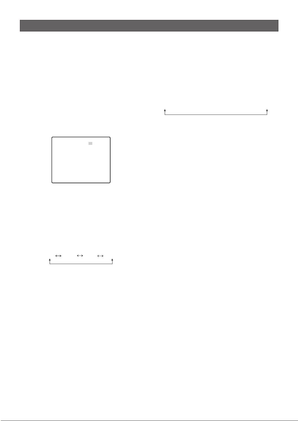
Operation Example 1: When following a preset
sequence (with alarm output),
the camera switches to auto
tracking when it reaches a
particular preset position,
and then returns to the preset
sequence after 30 seconds of
auto tracking.
Alarm Output 1 Auto Tracking Stop
Sequential
Movement
Auto Tracking In
Progress
30 seconds
Sequential
Movement
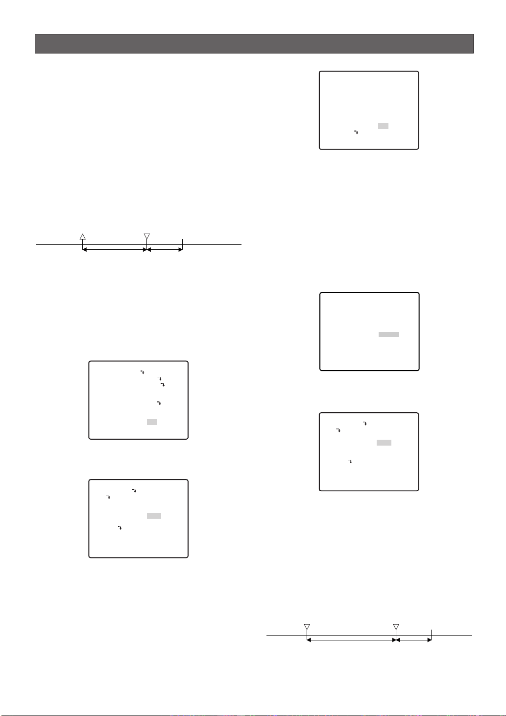
1. Configure the PRESET settings (page 33).
Register each preset position.
For each registered preset position, select ON for
AUTO TRACK for the positions you want to include
in the auto tracking. Auto tracking will not include
any preset position whose AUTO TRACK setting is
OFF.
PRESET NO. 1*
POSITION SET
PRESET ID
ALC/MANUAL
AF MODE
DWELL TIME
SCENE FILE
PRESET SPEED
AUTO TRACK
RET TOP DEL
ON
ALC
MANUAL L
10S
1
••••••I255
L H
ON
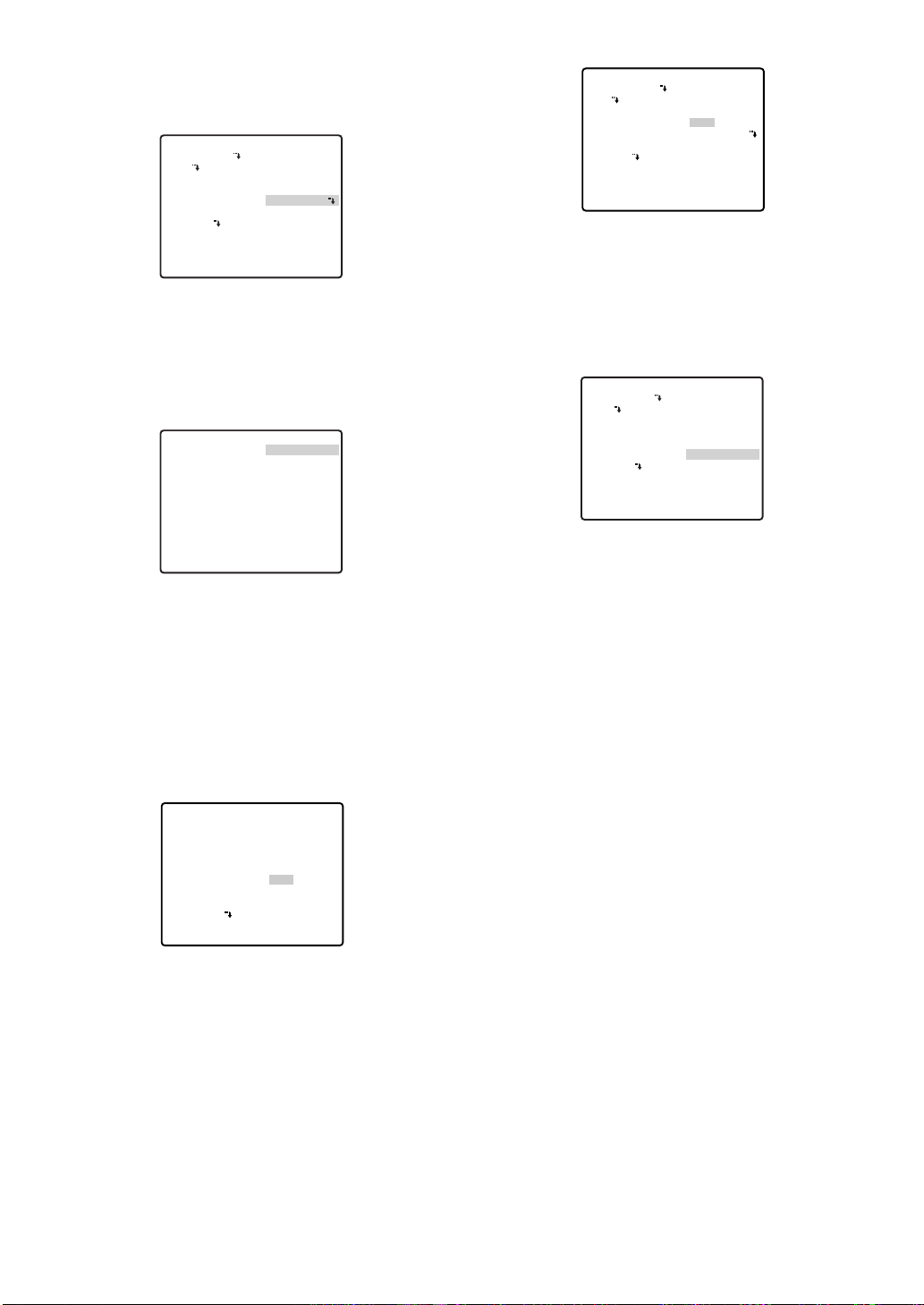
2. Configure the AUTO MODE setting (page 35).
Select SEQ for the AUTO MODE setting.
**PAN/TILT SETUP**1/2
PRESET 1
MAP
HOME POSITION
SELF RETURN
AUTO MODE
AUTOPAN KEY
PATROL
PRIVACY ZONE
IMAGE HOLD
DIGITAL FLIP
PROPO.P/T
OFF
OFF
SEQ
AUTO PAN
OFF
OFF
ON
ON
3. Configure the AUTO TRACK setting (page 41).
Select ON for the ALARM setting.
Configure the other parameters in accordance with
the operating environment.
** AUTO TRACKING **
CAMERA HEIGHT
OBJECT SIZE
SENSITIVITY
TRACKING MODE
ZOOM CONTROL
AUTO RELEASE
LOST MODE
ALARM
AREA SET
INDICATOR
RET TOP
2.50M
SMALL
MID
MID
CONTINUOUS
OFF
ZOOM-OUT
ON
OFF
Important: Failure to configure settings in
accordance with the operating environment can
cause operational errors. Configure the settings
while carefully checking the AUTO TRACK setting
(page 41).
Note: If the alarm is turned on, an alarm signal is
continually output from ALARM OUT 1 while an auto
tracking operation is in progress.
4. Configure ALARM IN/OUT settings (page 45).
Select ALARM for CNT-CLS1.
**ALARM IN/OUT**
ALARM IN1
ALARM IN2
ALARM IN3
ALARM IN4
CNT-CLS 1
TIME OUT
CNT-CLS 2
COAX ALM OUT
RET TOP
OFF
OFF
OFF
OFF
ALARM
100MS
OFF
OFF
5. Configure the SELF RETURN setting (page 35).
Select either 30S or SEQ.
**PAN/TILT SETUP**1/2
PRESET 1
MAP
HOME POSITION
SELF RETURN
AUTO MODE
AUTOPAN KEY
PATROL
PRIVACY ZONE
IMAGE HOLD
DIGITAL FLIP
PROPO.P/T
OFF
30S SEQ
SEQ
AUTO PAN
OFF
OFF
ON
ON
Operation Example 2: While auto panning, the
camera moves to Preset
Position 1 in accordance with
input at ALARM IN 1 and then
performs auto tracking. To
return to auto panning
operation one minute after
auto tracking starts (50
seconds of auto tracking and
10 seconds of self-return)
Alarm IN 1 Auto Tracking Ends
-21-
Auto Panning
Auto Tracking Enabled
50 seconds
10 seconds
Auto Panning
Page 22
1. Configure the AUTO MODE setting (page 35).
Select AUTO PAN for the AUTO MODE setting and
then configure the AUTO PAN settings.
**PAN/TILT SETUP**1/2
PRESET 1
MAP
HOME POSITION
SELF RETURN
AUTO MODE
AUTOPAN KEY
PATROL
PRIVACY ZONE
IMAGE HOLD
DIGITAL FLIP
PROPO.P/T
OFF
OFF
AUTO PAN
AUTO PAN
OFF
OFF
ON
ON
**PAN/TILT SETUP**1/2
PRESET 1
MAP
HOME POSITION
SELF RETURN
AUTO MODE
AUTOPAN KEY
PATROL
PRIVACY ZONE
IMAGE HOLD
DIGITAL FLIP
PROPO.P/T
OFF
10S APAN
AUTO PAN
AUTO PAN
OFF
OFF
ON
ON
Operation Example 3: Enable manual switching to
auto tracking while tracking a
target manually.
2. Configure PRESET (page 33) and ALARM IN/OUT
(page 45) settings.
Register the preset position where you want auto
tracking to start as preset position 1. To perform
auto tracking after ALARM IN 1, select
AUTOTRACK for the ALARM IN1 setting.
**ALARM IN/OUT**
ALARM IN1
ALARM IN2
ALARM IN3
ALARM IN4
CNT-CLS 1
TIME OUT
CNT-CLS 2
COAX ALM OUT
RET TOP
AUTOTRACK1
OFF
OFF
OFF
OFF
100MS
OFF
OFF
Note: ALARM IN1 through 4 can be configured with
preset positions 1 through 4 to specify the auto
tracking start position in accordance with the input
terminal where the alarm is input.
3. Configure the AUTO TRACK setting (page 41).
Specify the auto tracking period from the start of
AUTO TRACK to the end. Specify 50S for the AUTO
RELEASE setting. Configure the other parameters in
accordance with the operating environment.
**AUTO TRACKING**
CAMERA HEIGHT
OBJECT SIZE
SENSITIVITY
TRACKING MODE
ZOOM CONTROL
AUTO RELEASE
LOST MODE
ALARM
AREA SET
INDICATOR
RET TOP
2.50M
SMALL
MID
MID
CONTINUOUS
50S
ZOOM-OUT
OFF
OFF
Important: Failure to configure settings in
accordance with the operating environment can
result in operation error. Configure the settings
while carefully checking the AUTO TRACK setting
(page 41).
4. Configure the SELF RETURN setting (page 35).
Select 10S, APAN for this setting.
1. Configure the AUTO PAN KEY setting.
Select AUTO TRACK for the AUTO PAN KEY
setting.
**PAN/TILT SETUP**1/2
PRESET 1
MAP
HOME POSITION
SELF RETURN
AUTO MODE
AUTOPAN KEY
PATROL
PRIVACY ZONE
IMAGE HOLD
DIGITA FLIP
PROPO.P/T
OFF
OFF
OFF
AUTO TRACK
OFF
OFF
ON
ON
2. Configure the AUTO TRACK setting (page 41).
Configure each parameter in accordance with the
operating environment.
Important: Failure to configure settings in
accordance with the operating environment can
result in operation error. Configure the settings
while carefully checking the AUTO TRACK setting
(page 41).
3. While using manual operation to track a target, start
auto tracking.
Perform manual operation (pan, tilt, zoom) to keep
the target being tracked in the center of the target
frame. Press the AUTO PAN key to start auto
tracking of the target.
Note: For information about target frame settings,
see INDICATOR (page 43).
Operation Example 4: Camera follows a preset
sequence without auto
tracking during the day, and
auto tracking from a home
position at night.
Important: The camera unit does not have a
schedule function. Schedule settings can be
configured only when the camera is connected to a
controller that is equipped with a schedule function
(WJ-HD300A, WJ-SX650, etc.)
-22-
Page 23
1. Configure the PRESET settings (page 33).
Register each preset position.
Select OFF for the AUTO TRACK setting of each of
the registered preset positions.
PRESET NO. 1*
POSITION SET
PRESET ID
ALC/MANUAL
AF MODE
DWELL TIME
SCENE FILE
PRESET SPEED
AUTO TRACK
RET TOP DEL
ON
ALC
MANUAL L
10S
1
••••••I255
L H
OFF
2. Configure the HOME POSITION (page 35) and
AUTO MODE (page 35) settings.
The HOME POSITION setting should be the position
from which you want to start auto tracking (such as
30POSI). For AUTO MODE, select SEQ.
**PAN/TILT SETUP**1/2
PRESET 1
MAP
HOME POSITION
SELF RETURN
AUTO MODE
AUTOPAN KEY
PATROL
PRIVACY ZONE
IMAGE HOLD
DIGITAL FLIP
PROPO.P/T
30
OFF
SEQ
AUTO TRACK
OFF
OFF
ON
ON
3. Configure the AUTO TRACK setting (page 41).
Configure each parameter in accordance with the
operating environment.
Important: Failure to configure settings in
accordance with the operating environment can
result in operation error. Configure the settings
while carefully checking the AUTO TRACK setting
(page 41).
4. Configure schedule function settings.
Use the Camera Event screen of the HD300 Series
Setup Tool or the SX650 Series Setup Tool.
(Refer to the user documentation that comes with
your controller for details about how to configure
schedule settings.)
Important:
A separate computer (PC) is needed to
use the Setup Tool.
-23-
Page 24
Using the setup menu
This manual describe procedures for operating system
controller WV-CU650.
All setting configuration procedures start from the
setup menu. This section explains how to display the
setup menu and provides details about the menu items
that it contains.
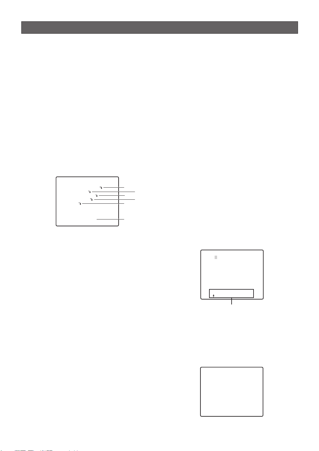
■ Displaying the Setup Menu
● When using the WV-CU650
(1) Select the camera (this camera), and the
monitor where displays the setup menu.
(2) Press the MENU button to display LCD MENU
CAM 101.
(3) Press the ENTER button or CAM (SET) button to
display CAMERA SETUP.
(4) Press the F1 button.
MODEL WV-CW974
CAMERA ID OFF
SCENE SELECT
PRESET POSITION
AUTO TRACKING
LANGUAGE
→
ADVANCED SETUP
Refer to the pages below for details.
q CAMERA ID Camera ID Settings
This page
w SCENE SELECT Scene Select Settings
Page 25
e PRESET POSITION Preset Position Settings
Page 25
r AUTO TRACKING Auto Track Settings
Page 41
t LANGUAGE Language Setting
Page 27
y ADVANCED SETUP Advanced Menu Settings
Page 27
q
e
t
y
w
r
■ Camera ID Settings
The camera ID is a series of alphanumeric
characters that indicate the location of the camera.
This item can be used to turn display of the camera
ID on the monitor screen on or off, and to input the
camera ID.
1. Move the cursor to CAMERA ID, and then tilt the
joystick left or right to toggle camera ID display on
and off.
2. Select ON or OFF, and then press the CAM (SET)
button. The factory default setting is OFF.
3. Use the joystick to move the cursor the character
you want to input, and then press the CAM (SET)
button.
This will cause the selected character to appear in
the camera ID input area. Repeat step 3 as many
times as necessary to input all of the characters for
the camera ID. (Example: DOOR)
To input a blank space
Move the cursor to SPACE, and then press the
CAM (SET) button.
To delete all previously input characters
Move the cursor to RESET, and then press the CAM
(SET) button.
To change previously input characters
Use the joystick to move the cursor to the camera
ID input area. Next, tilt the joystick left and right to
move the ↑ pointer to the character you want to
change. Finally, use step 3 above to input the new
character.
CAMERA ID-- 0123456789
ABCDEFGHIJKLM
NOPQRSTUVWXYZ
().,'":;&#!?=
+-*/%$
SPACE
---- POSI RET RESET
DOOR............
Camera ID Input area
4. Move the cursor to POSI, and then press the CAM
(SET) button.
This will display the ID position setting menu.
5. Use the joystick to select a camera ID display
position, and then press the MON (ESC) button.
This registers the camera ID display position and
returns to the camera setting menu.
-24-
DOOR
Page 25

■ Scene Select Settings
Display the scene select setting menu from the setup
menu to configure scene select settings. First, display
the scene select setting menu.
1. Display the setup menu (page 24), move the cursor
to SCENE SELECT O, and then press the CAM
(SET) button.
This will display the scene select setting menu.
**SCENE SELECT**
SCENE INDOOR(L)
LOAD
RET TOP
● Scene Select Settings
Use the following procedure to configure scene select
settings.
1. Move the cursor to SCENE, and then tilt the joystick
left or right to change the scene setup.
INDOOR (L) : Indoor setting (picture quality
priority)
INDOOR (H) : Indoor setting (sensitivity
priority)
OUTDOOR (L) : Outdoor setting (picture
quality priority)
OUTDOOR (H) : Outdoor setting (sensitivity
priority)
Settings related to the picture switch depending on
the scene settings. Scene select settings and
relationship to other settings are shown in the table
below.
AGC SENS UP SHUTTER
INDOOR (L) MID OFF OFF
INDOOR (H) HIGH ×2 AUTO OFF
OUTDOOR (L) MID OFF AUTO
OUTDOOR (H) HIGH ×2 AUTO AUTO
BW DNR WHITE BAL
INDOOR (L) OFF LOW ATW1
INDOOR (H) OFF HIGH ATW1
OUTDOOR (L) AUTO LOW ATW2
OUTDOOR (H) AUTO HIGH ATW2
2. Move the cursor to LOAD, and then press the CAM
(SET) button.
This will cause the setup you selected for SCENE in
step 1 to be applied to the image.
■ Preset Position Settings
● Position Number Selection (MAP)
You could use the MAP item on the pan/tilt setup menu
instead of the PRESET item to select a position number.
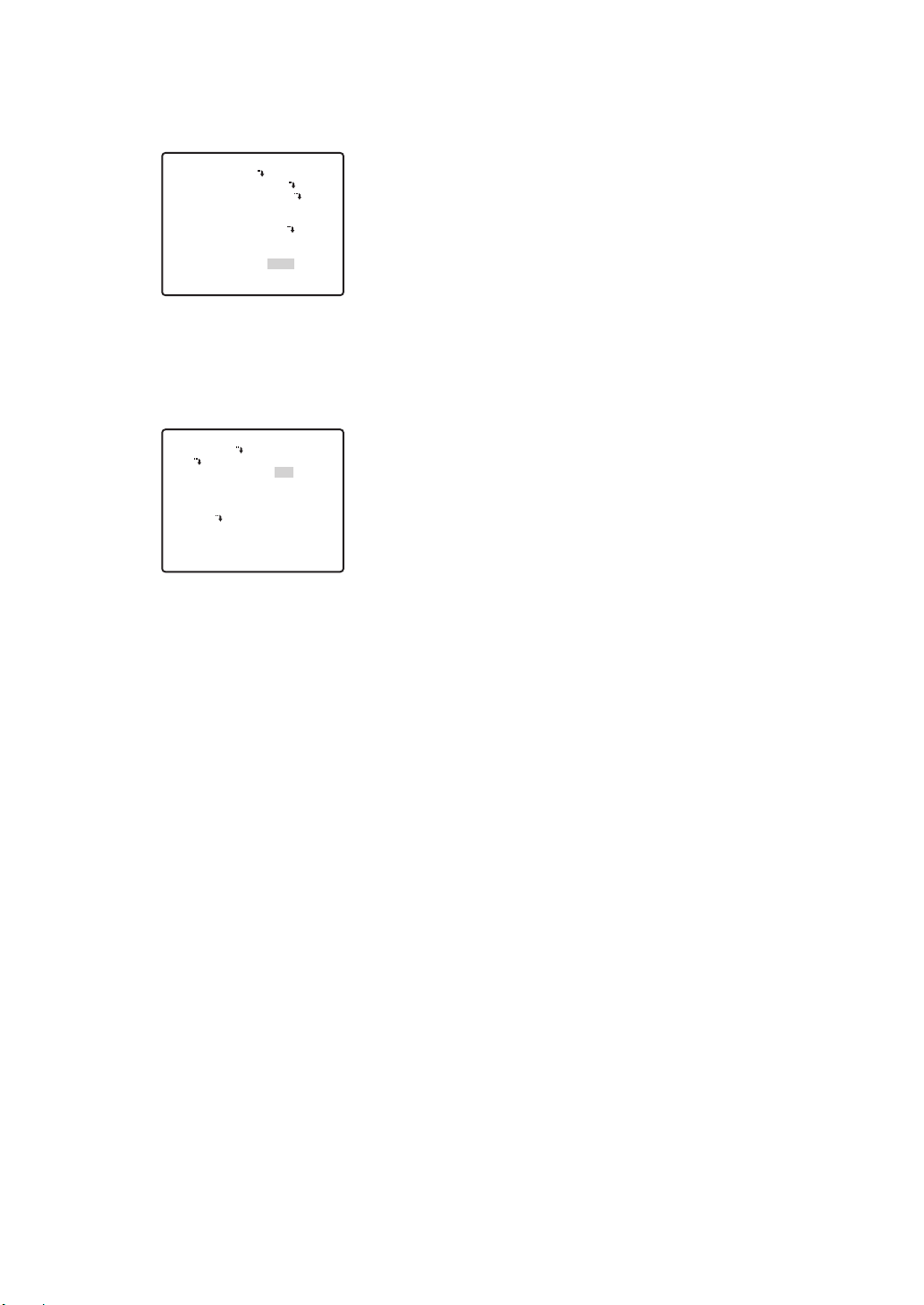
1. Move the cursor to PRESET POSITION O, and then
press the CAM (SET) button.
**PRESET POSITION**
2
1*
6
5
10
9
14
13
18
17
22
21
26
25
30
29
ID:DOOR
033-064 225-256
RET TOP
2. Move the cursor to the number you want to select,
and then press the CAM (SET) button.
This registers the position number setting and
displays the preset setting menu. (this page)
To select a position number in the range of 033 to
064, move the cursor to 33-64 in the lower left corner
of the menu, and then press the CAM (SET) button.
Preset numbers set subsequently are the same.
**PRESET POSITION**
34
33
38
37
42
41
46
45
50
49
54
53
58
57
62
61
ID:
065-096 001-032
RET TOP
Notes:
• An asterisk (*) to the right of a position number
indicates that it already has a preset position
assigned to it.
The home position number is indicated by the
letter H next to the asterisk.
• When the cursor is located at a position number
that has a position ID, the position ID text
appears next to ID: on the menu screen.
● Position Setting (POSITION SET)
The position setting can be used to specify the camera
position (pan and tilt), the lens zoom setting, and the
focus setting.
1.
Move the cursor to POSITION SET O and press the
CAM (SET) button to display the position setting menu.
PRESET NO. 1*
POSITION SET
PRESET ID
3
7
11
15
19
23
27
31
35
39
43
47
51
55
59
63
ON
4
8
12
16
20
24
28
32
36
40
44
48
52
56
60
64
-25-
RET TOP DEL
Page 26

2. Move the cursor to →PUSH SET to the right of
PAN/TILT, and then press the CAM (SET) button to
display the PAN/TILT setting menu.
** POSITION 1 **
PAN/TILT
ZOOM/FOCUS
PAN OFFSET SET
RET TOP
FLOOR1
DOOR
→PUSH SET
→PUSH SET
←
0
→
3. Use the joystick to position the camera, and then
press the CAM (SET) button.
** POSITION 1 **
PAN/TILT
ZOOM/FOCUS
U TILT D/L PAN R
PAN OFFSET SET
RET TOP
FLOOR1
DOOR
→
PUSH SET
→
PUSH SET
← 0
→
4. Move the cursor to → PUSH SET to the right of
ZOOM/FOCUS, and then press the CAM (SET)
button to display the ZOOM/FOCUS setting menu.
** POSITION 1 **
PAN/TILT
ZOOM/FOCUS
U ZOOM D/L FOCUS R
PAN OFFSET SET ←
RET TOP
FLOOR1
DOOR
→
PUSH SET
→
PUSH SET
0
→
5. Move the joystick left, right, up and down to adjust
the position of the lens focus, and then press the
CAM (SET) button.
Notes:
•
Focusing may be difficult, because of the distortion
caused by the curve of the dome cover, when the
camera is at an angle that is close to horizontal.
•
A different position number can be selected by moving
the cursor to the position number at the top of the
position setting menu and tilting the joystick left and
right. Pressing the CAM (SET) button will change to the
setting screen for the newly selected position number.
• The currently registered camera ID and preset ID
appear at the bottom of the position setting menu.
•
When using a system device other than the WVCU650/CU950*, WJ-HD309A/HD316A over 65
position numbers cannot be set. (as of September
2005)
* Operation procedure may vary depending on
the version of the system controller's software.
For Ver.1.xx or earlier: only camera function
operations are supported
For Ver.2.xx or later: PRESET/PGM PRESET
button is also supported
Align the cursor here
** POSITION 1* **
PAN/TILT
ZOOM/FOCUS
PAN OFFSET SET ← 0
RET TOP
FLOOR1
DOOR
→PUSH SET
→
PUSH SET
→
● Adjusting Camera Position When
Changing Cameras (PAN OFFSET SET)
The system controller etc. has a function for
downloading (saving) and uploading (recovering)
setting information for the camera. This function allows
you to upload (recover) original setting information that
has been downloaded (saved) before some
unforeseen damage or malfunction causes setting
information in the camera to be lost. However, there
may be some slight differences in images from those
uploaded (recovered) when the camera is changed.
The "PAN OFFSET SET" function is for adjusting these
differences.
1. Align the cursor with "PAN OFFSET SET" with the ←
or → arrow, and press the CAM (SET) button to set
the offset value.
Set the offset value to 0.0, or in a range of -10 to
+10. All preset positions for the camera's position
are adjusted according to the offset value.
Important: Data is not compatible with existing
cameras. Uploading setting information from
existing cameras will damage data in the camera. If
data in the camera is damaged, download camera
setting information from a camera that still has the
factory settings and then upload it to the camera
with the damaged data.
● Preset ID Setting (PRESET ID)
The preset ID is a series of alphanumeric characters
that indicate the location of the camera. This item can
be used to turn display of the preset ID on the monitor
screen on or off, and to input the preset ID.
1. Move the cursor to PRESET ID, and then tilt the
joystick left or right to toggle preset ID display on
and off.
PRESET NO. 1*
POSITION SET
PRESET ID
RET TOP DEL
2. Select ON or OFF, and then press the CAM (SET)
button.
This will display the preset ID setting menu.
-26-
ON
Page 27

3. Use the joystick to move the cursor the character you
want to input, and then press the CAM (SET) button.
The text input procedure is the same as that for
camera ID input.
See steps 3 through 5 under “Camera ID Settings”
on page 24 for information about inputting the text
for the preset ID and specifying its position on the
display.
PRESET NO. 1*
0123456789
ABCDEFGHIJKLM
NOPQRSTUVWXYZ
().,'":;&#!?=
+-*/%$
SPACE
COPY POSI RET RESET
DOOR............
To copy the preset ID of another position number
Move the cursor to COPY, and then press the CAM
(SET) button. This displays the preset ID of the
position number preceding the one you are
currently configuring. Each press of the CAM (SET)
button scrolls back to the next sequential position
number and displays its preset ID.
■ Language Setting
1. Move the cursor to LANGUAGE O, and then press
the CAM (SET) button.
2. On the 8-language selection menu that appears,
select the language you want to use.
The factory default setting is English.
* All of the example screens in these Operating
Instructions show English display messages.
3. Move the cursor to SET, and then press the CAM
(SET) button.
When you switch the languages, the password and
titles are deleted.
* The item that was set flashes when the language is
being changed and stops flashing when the
language has been changed. Do not operate the
system controller when changing settings.
* If you have selected either Japanese or Chinese as
the language, only the IDs and titles can be set in
katakana or Chinese.
* The “LANGUAGE” display remains in English even
when the language setting is changed.
■ Advanced Menu Settings
The advanced setup menu can be displayed from the
setup menu.
1. Display the setup menu (page 24), move the cursor
to → ADVANCED SETUP, and then press the CAM
(SET) button.
This will display the advanced setup menu.
MODEL WV-CW974
CAMERA
PAN/TILT
AUTO TRACKING
ALARM
SPECIAL
COMMUNICATION
SCENE SELECT
LANGUAGE
QUICK SETUP
PASSWORD LOCK OFF
All items can be set on the advanced setup menu.
To switch back to the quick setup menu from the
detailed menu, move the cursor to →QUICK SET
UP, and then press the CAM (SET) button.
Refer to the pages below for details of setup menu
items.
q CAMERA Camera Settings Page 28
w PAN/TILT Pan/Tilt Settings Page 33
e AUTO TRACKING Auto Tracking Settings
Page 41
r ALARM Alarm Settings Page 44
t SPECIAL Special Settings Page 47
y COMMUNICATION* Communication Settings
Page 20
u SCENE SELECT Scene Select Settings
Page 25
i LANGUAGE Language Setting
This page
o QUICK SETUP Quick Menu Settings
Page 24
!0 PASSWORD LOCK Password Settings
Page 50
* This item appears only when RS485 settings are
configured with the DIP switches.
q
e
t
u
o
w
r
y
i
!0
-27-
Page 28
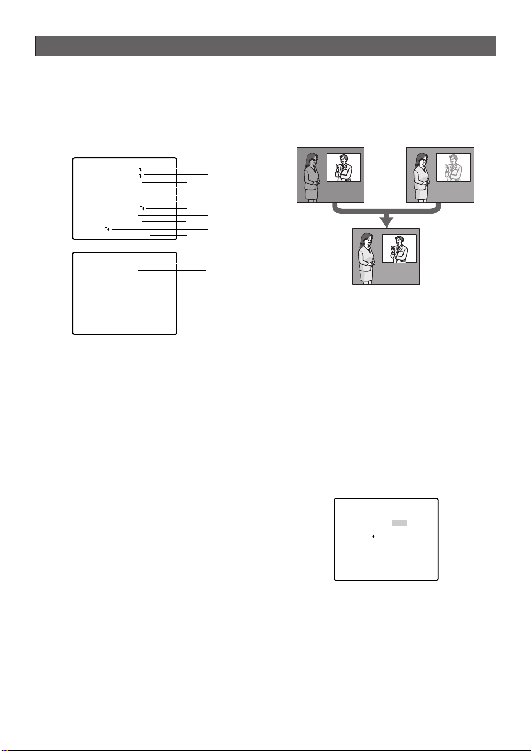
Camera settings
■ Using the Camera Setup Menu
Display the camera setup menu from the setup
menu (Advanced Menu) to configure camera
settings (page 27).
1. Display the setup menu (page 24), move the cursor to
CAMERA O, and then press the CAM (SET) button.
This will display the camera setup menu.
**CAMERA SETUP** 1/2
CAMERA ID OFF
ALC/MANUAL ALC
SHUTTER AUTO
AGC ON(MID)
SENS UP OFF
SYNC INT
WHITE BAL ATW1
DNR LOW
RESOLUTION HIGH
BW MODE
AF MODE AUTO L
**CAMERA SETUP** 2/2
ZOOM LIMIT ×30
STABILIZER OFF
RET TOP
* The following sections numbered q to !3 explain
how to use each of the camera setup menu items.
(1) Camera ID (CAMERA ID)
See page 24 for information on the camera ID
settings method. The factory default setting is OFF.
(2) Light Control (ALC/MANUAL)
1. Move the cursor to ALC/MANUAL, and then tilt the
joystick left or right to toggle between ALC and
MANUAL.
ALC : Enables automatic lens iris adjustment in
accordance with subject brightness.
Select this ALC when using SUPER-D 3.
This is the factory default setting.
MANUAL: Adjust the lens iris with the IRIS button on
the system controller. Fixes the lens iris.
Note: The backlight compensation submenu
associated with this menu is described separately
and should be set up after installing the camera at
the site and observing the actual site picture.
2. If ALC is set in step 1, press the CAM (SET) button
to set SUPER-D 3.
SUPER-D 33(Super Dynamic 33)
When there is wide variation between the illumination of
light and dark areas of the location being monitored,
the camera adjusts the lens iris in accordance with the
bright areas. This causes loss of detail in dark areas.
Conversely, adjusting lens brightness for the dark
areas cause brighter area to become washed out.
q
e
t
u
o
!1
!2
w
r
y
i
!0
!3
SUPER-D 3 digitally combines an image that is set up
for a clear view of bright areas with an image that is set
up for a clear view of dark areas, creating a final image
that preserves overall detail.
Loss of detail
in dark areas...
Wash out of
bright areas ...
Two images
digitally combined
to create a clear
final image
Notes:
• SUPER-D 3 is supported only when ALC is
selected for light control (ALC/MANUAL).
• Camera settings are limited to the following when
SUPER-D 3 is turned on.
SHUTTER: OFF, AUTO (page 29)
SENS UP : OFF, AUTO (page 29)
• If lighting conditions cause either of the following
phenomena, turn off SUPER-D 3.
(1) Screen flickering or abnormal color
(2) Digital noise in the bright areas of the screen
3. Move the cursor to SUPER-D3, and then tilt the
joystick left or right to toggle between on and off.
ON : Turns on SUPER-D 3. (Go to Step 6)
OFF : Turns off SUPER-D 3. (Go to Step 4)
This is the factory default setting.
**ALC CONT**
BACK LIGHT COMP
SUPER-D3
MASK SET
LEVEL
RET TOP
OFF
•I••••• 64
- +
4. Move the cursor to MASK SET O, and then press
the CAM (SET) button.
This will display the mask area screen, with the
cursor in the upper left cell.
5. Mask the cells in the area where background
lighting is bright. Masking an area will cause its
brightness level to be ignored.
Use the following steps to perform masking
(1) Tilt the joystick up and down, and left and right
to move the cursor to a cell you want to mask.
-28-
Page 29
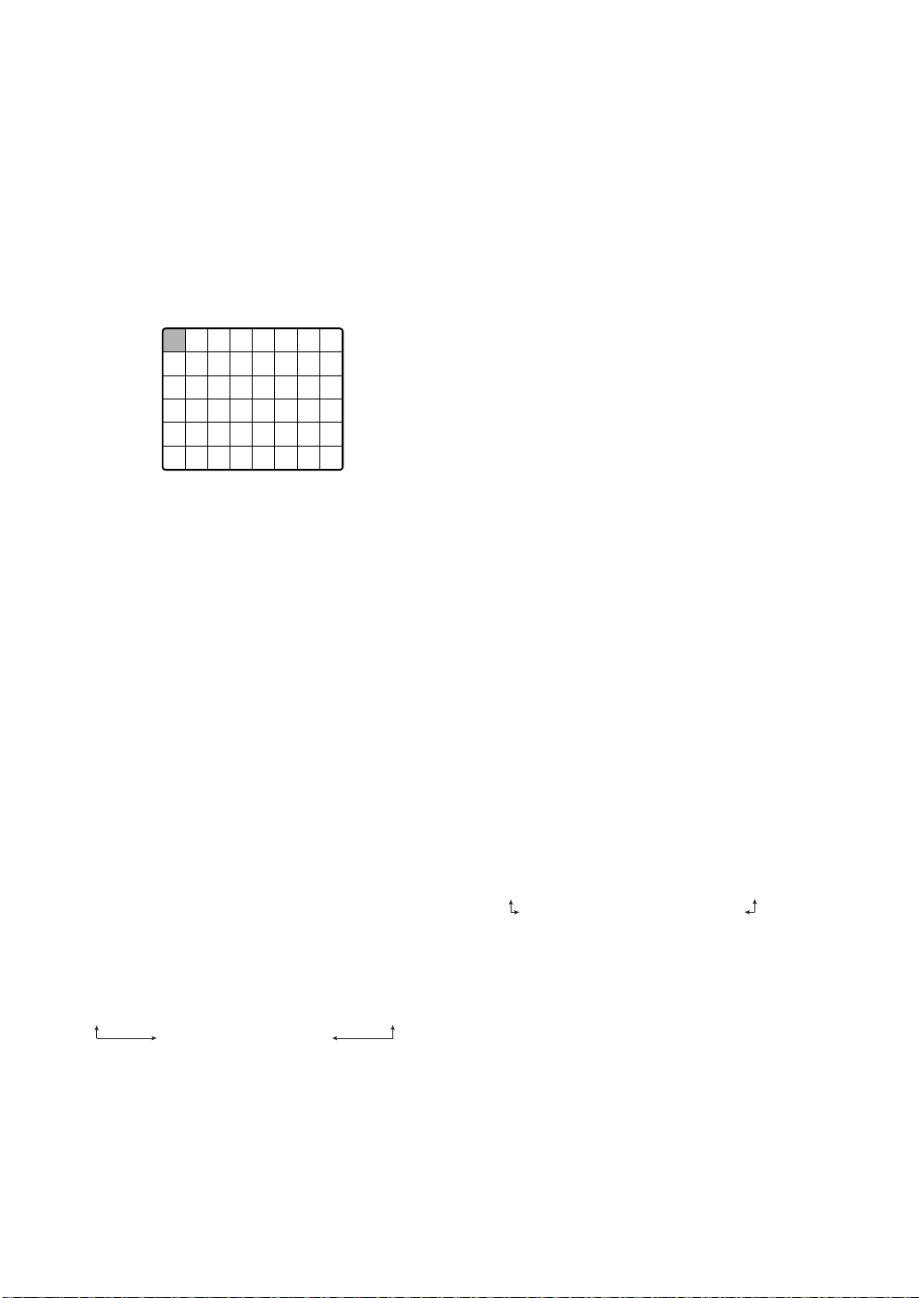
(2) Press the CAM (SET) button to mask the cell.
Moving the cursor to a cell that is already
masked causes the blinking pattern of the
cursor to alternate between horizontal stripes
and white.
Pressing the CAM (SET) button while the cursor
is located at a masked cell cancels the masking
of the cell.
To cancel all masking areas, press the F3
button.
(3) After masking all of the cells you want, press the
MON (ESC) button to return to the ALC CONT
menu in step 1.
6. Move the cursor to LEVEL, and then tilt the joystick
left and right to adjust the picture output level
(picture contrast).
If you selected ON in step 3 of this procedure, best
results can be obtained by setting a contrast level
that is somewhat high. A contrast level that is too
high, however, may increase the tendency of
afterimages and noise.
Note: If operation of the system controller's IRIS
(OPEN, CLOSE) button during operation is done
after the menu is closed, the LEVEL on the
CAMERA menu is reflected and stored for these
settings. However, if the camera is in a preset
position, it is reflected as a parameter of the preset
position. To return to the initial factory default level,
execute the system controller's iris reset.
(3) Shutter Speed (SHUTTER)
1. Move the cursor to SHUTTER, and then tilt the
joystick left or right to select a shutter speed
setting.
Tilting the joystick cycles through the shutter speed
settings display in the sequence shown below.
(unit: sec)
When SUPER-D 33is turned off
OFF ↔ AUTO ↔ 1/100 ↔ 1/250 ↔ 1/500 ↔ 1/1000
1/10000 ↔ 1/4000 ↔ 1/2000
When SUPER-D 33is turned on
OFF ↔ AUTO
AUTO: This setting, by moving the shutter
automatically when necessary, provides a
clearer picture of extremely bright objects
outdoors, etc. This is the factory default
setting.
OFF : Fixed at 1/60 seconds.
Notes:
• When AUTO is selected for the shutter setting,
fluorescent lighting may cause flickering of the
picture. If this happens, select OFF or 1/100 for
the shutter speed setting.
• AUTO is disabled when MANUAL is selected for
light control (ALC/MANUAL) and FIX is selected
for electronic sensitivity enhancement (SENS UP).
(4) Gain Control (AGC)
1. Move the cursor to AGC, and then tilt the joystick
left or right to select a gain control setting.
ON (LOW) : Low gain
ON (MID) : Medium gain. This is the factory default
setting.
ON (HIGH) : High gain
OFF : Fixed gain
Note: When AGC is turned on, the noise reduction
function automatically activates under low illumination
to reduce digital noise. This also, however, can cause
afterimages to be generated by moving objects, and
by panning and tilting the camera. For more
information, see the DNR setting (page 31).
(5) Electronic Sensitivity Enhancement (SENS UP)
1. Move the cursor to SENS UP, and then tilt the
joystick left or right to select an electronic sensitivity
enhancement setting.
The electronic sensitivity enhancement setting can
be changed only when OFF or AUTO is selected for
the shutter speed (SHUTTER) setting. Tilting the
joystick cycles through the settings display in the
sequence shown below. The factory default setting
is OFF.
When SUPER-D 33is turned off
OFF ↔ X2 AUTO ↔ X4 AUTO ↔ X6 AUTO ↔ X10 AUTO ↔ X16 AUTO
↔↔
X32 FIX X32 AUTO
X16 FIX ↔ X10 FIX ↔ X6 FIX ↔ X4 FIX ↔ X2 FIX ↔ OFF
When SUPER-D 33is turned on
OFF ↔ X2 AUTO ↔ X4 AUTO ↔ X6 AUTO
X32 AUTO ↔ X16 AUTO ↔ X10 AUTO
Notes:
• The following are the differences between AUTO
and FIX.
AUTO: Selecting X32 AUTO, for example,
automatically increases sensitivity, up to
a maximum of 32 times.
FIX :Selecting X32 FIX, for example,
increases sensitivity 32 times.
The FIX settings cannot be selected when the
shutter speed (SHUTTER) setting is 1/100.
• SENS UP is set to 2x automatically if it is set
higher than 2x when auto tracking starts.
Caution: Turning on SENS UP can cause digital noise
and white spots (blemish) to appear in the picture.
-29-
↔↔
Page 30

(6) Synchronization (SYNC)
This camera supports the following three sync modes,
which are listed in priority sequence from highest
priority to lowest.
(1) Multiplexed vertical drive (VD2)
(2) Internal sync (INT)
(3) Line-lock (LL)
Input of a multiplexed vertical driver (VD2) signal
automatically switches to VD2 sync, regardless of the
camera's current sync mode (SYNC). In this case, the
camera setting menu shows EXT (VD2) for the SYNC
setting, which cannot be changed to internal sync
(INT) or line-lock (LL).
The following procedures explain how to select internal
sync (INT) and line-lock (LL), and how to perform
phase adjustment when line-lock (LL) is selected.
1. Move the cursor to SYNC, and then tilt the joystick
left or right to select the sync mode.
INT :Internal sync. This is the factory default setting.
LL : Line-lock (Cannot be used in areas with 50 Hz
power.)
Selecting LL and pressing the CAM (SET) button
will display the SYNC setting menu, which can be
used for configuring detailed settings. (This page)
● Adjusting the Phase for Line-lock
Synchronization
Connect the video output signal of the camera being
adjusted and the reference video output signal to a
two-input oscilloscope.
Set the oscilloscope to the vertical rate, and then
expand the vertical sync portion on the oscilloscope.
1. Move the cursor to COARSE, and then tilt the
joystick left or right to align the coarse adjustment
of the vertical phases of the camera being adjusted
with that of the reference camera.
Coarse adjustment be performed across 16 steps
(1 through 16). Adjusting past step 16 returns to
step 1.
** SYNC **
V PHASE
COARSE
FINE
RET TOP
2. Move the cursor to FINE, and then tilt the joystick
left or right to align the fine adjustment of the
vertical phases of the camera being adjusted with
that of the reference camera.
1(1--16)
••I•••• 96
- +
Notes:
• To reset COARSE and FINE to the preset values,
press the F3 button. For WV-RM70, press the
right and left switches simultaneously. COARSE
is preset to zero-crossing of the AC line phase.
• If the AC line phase contains spike noise, etc.,
the vertical phase of the video output signal may
be disturbed.
(7) White Balance (WHITE BAL)
1. Move the cursor to WHITE BAL, and then tilt the
joystick left or right to select a white balance mode.
(1) Auto-Tracing White Balance Mode (ATW1/ATW2)
In this mode, the camera continually monitors
the color temperature of the light source and
automatically adjusts white balance.
The following are the approximate supported
color temperature ranges in this mode.
ATW1: 2,700 K to 6,000 K. This is the factory
default setting.
ATW2: 2,000 K to 6,000 K (Mode recommended
for sodium lighting)
Proper white balance may not be possible under
the following conditions. In such cases, use the
AWC while balance mode.
• When the subject contains mostly dark colors
• When the light source is a deep blue sky or
twilight
• When illumination of the subject is low
(2) Auto-Tracing White Balance Control (AWC)
In this mode, the supported color temperature
range is approximately 2,000 K to 10,000 K. This
mode is best in locations where the light source
is constant.
(a) To select AWC, tilt the joystick left and select
AWC→PUSH SET.
(b) Press the CAM (SET) button to start white
balance adjustment. PUSH SET is highlighted
on the display while white balance adjustment is
being performed.
• PUSH SET becomes unhighlighted again when
white balance adjustment is complete. Tilt the
joystick right to display AWC.
• If white balance adjustment cannot be completed
for some reason, PUSH SET will remain
highlighted on the display. If this happens, it could
mean that the color temperature is outside the
supported range, or that illumination is too low.
2. Select ATW1, ATW2, and AWC, then press the CAM
(SET) button, either the ATW setting menu or the
AWC setting menu appears, and you can fine tune
the white balance.
Move the cursor to R or B, and then tilt the joystick left
or right to fine tune the level. The R is red and the B is
blue, moving in the + direction makes the colors
darker, moving in the - direction makes them lighter.
-30-
Page 31

** ATW1 **
R
B
RET TOP
•••I•••129
- +
•••I•••127
- +
Note: White balance is adjusted in accordance with
on-screen color temperature, which the camera
detects automatically. Correct adjustment may not
be possible if a strong light source is shining on the
screen.
(8) Digital Noise Reduction (DNR)
1. Move the cursor to DNR, and then tilt the joystick
left or right to select a digital noise reduction (DNR)
setting.
LOW : Low DNR, Low afterimage. This is the factory
default setting.
HIGH : High DNR, High afterimage
(9) Resolution (RESOLUTION)
1. Move the cursor to RESOLUTION, and then tilt the
joystick left or right to select NORMAL or HIGH.
NORMAL: Sets horizontal resolution to a minimum
of 480 TV lines. (In color mode)
HIGH :Sets horizontal resolution to a minimum
of 520 TV lines. (In color mode) This is
the factory default setting.
(10) Black and White Mode (BW MODE)
Moving the cursor to BW MODE and pressing the CAM
(SET) button displays a BW MODE setting menu.
Use the BW MODE setting menu to configure black
and white mode settings.
1. Move the cursor to BW, and then tilt the joystick left
or right to select a black and white control setting.
AUTO : The camera automatically switches
between the color mode and the black and
white mode in accordance with picture
brightness (illuminance).
The black and white mode is selected
when lighting is low, while the color mode is
selected for bright lighting.
ON : Selects the black and white mode.
OFF : Selects the color mode. This is the factory
default setting.
** BW MODE **
BW
LEVEL
DURATION TIME
BURST(BW)
AUTO
HIGH
•I••
S L
ON
Note: The above setting cannot be configured
when BW is selected for the ALARM IN 4 setting
(page 46).
2. If you selected AUTO in step 1, move the cursor to
LEVEL and then tilt the joystick left to select the
threshold illuminance level for switching between
the color mode and the black and white mode.
The illuminance shown below is based on the
assumption that the camera is used in an area lit by
halogen lamps, and that AGC on the menu is set to
MID.
LOW : Switches to the black and white mode when
illuminance around the camera is
approximately 1.5 lux{fc} or lower (when
AGC ON (MID), SENS UP OFF is set).
HIGH : Switches to the black and white mode when
illuminance around the camera is
approximately 3 lux{fc} or lower (when AGC
ON (MID), SENS UP OFF is set). This is the
factory default setting.
Note: When near-infrared lamps are used, the
image may be displayed out of focus and mode
switching may not perform automatically.
3. If you selected AUTO in step 1, move the cursor to
DURATION TIME and then tilt the joystick left to
select the time the camera should wait before
switching between the color mode and the black
and white mode after there is a change in the
illuminance level.
Available Settings: 10 s - 30 s - 60 s - 300 s
(S) (L)
Note: When AUTO is selected, switching between
the color mode and the black and white mode is not
performed while pan, tilt, zoom, or focus is being
performed.
4. Move the cursor to BURST (BW), and then tilt the
joystick left or right to turn burst signal output on or
off.
This setting is for black and white mode display.
ON : Turns on burst signal output. This is the
factory default setting.
OFF : Turns off burst signal output.
Note: With some monitors and VCR models, output
of a camera images in the black and white mode
will not display a proper image unless a burst signal
is provided. Select ON for this setting when using
equipment that requires a burst signal.
RET TOP
-31-
Page 32

(11) Auto Focus (AF MODE)
1. Move the cursor to AF MODE, and then tilt the
joystick left or right to select an auto-focus mode
setting.
MANUAL S.M.L : Activates auto-focus when the AF
button on the system controller is
pressed.
AUTO S.M.L : Auto focus is used automatically
when PAN, TILT or ZOOM are
used in manual operation.
The letters S (Small), M (Medium), and L (Large)
indicate the size of the auto-focus sensing area.
The factory default setting is AUTO L.
Notes:
• The AUTO (S.M.L.) setting can be selected only
when OFF, x2 FIX or x2 AUTO is selected for the
electronic sensitivity enhancement (SENS UP).
Any other SENS UP setting causes MANUAL
(S.M.L.) to be selected automatically for the
auto-focus mode (AUTO).
• Zooming up from WIDE can cause the image to
go out of focus.
• Auto-focus may not be possible with the types of
objects listed below. For such objects, focus
manually.
Example: • Shiny or high intensity objects
• Objects shot through wet or dirty
glass
• Pictures that are a mixture of distant
and nearby objects
• White walls and other single-color
objects
• Venetian blinds and other vertically
striped objects
• Slanted objects
• Objects illuminated with low lighting
Auto-focus focuses on the object in the center of
the picture, so objects around the outside periphery
of the picture will not be in focus.
(13) Auto Image Stabilizer (STABILIZER)
This function electronically compensates for an
unstable camera image due to movement of a
mounting pole or bracket.
1. Move the cursor to STABILIZER, and then tilt the
joystick left or right to turn the stabilizer on or off.
The default setting is OFF.
ON :Automatically compensates for an unstable
image.
OFF : Image stabilizer will not operate. This is the
factory default setting.
Notes:
• The stabilizer may not be effective for the
following subjects.
Example: • Objects illuminated with low lighting
• Single-color objects (white walls etc)
• Fast moving periodic action, such as
mechanical vibration, may not be tracked.
• The stabilizer does not work during
PAN/TILT/ZOOM/FOCUS or when the camera
setup menu is open.
• When set to ON, some effective pixels on the
edge of the CCD are used by the stabilization
function. This may result in a small reduction in
resolution and a narrower angle of view. After
activating the image stabilizer function, check
that the field of view is correct.
• Auto tracking may not operate normally when
ON is selected for STABILIZER.
(12) Zoom Limit (ZOOM LIMIT)
1. Move the cursor to ZOOM LIMIT, and then tilt the
joystick left or right to select a zoom limit setting.
When doing manual operation, zoom operation
cannot go beyond the zoom limit.
Optical zoom ranges from 1 to 30 magnifications,
while digital zoom is used for higher magnifications
(up to 300).
The factory default setting is x30 (30x optical
zoom).
Notes:
• If zoom limit is set to more than 30x, then zoom
operation pauses at 30x magnification.
• Increasing the zoom to over 30x magnification
(digital zoom) decreases the resolution.
• You cannot set a zoom magnification of greater
than 30x as a preset position.
• Auto tracking cannot be used with a zoom
magnification of 30x or greater.
-32-
Page 33

Pan/Tilt settings
■ Using the Pan/Tilt Setup Menu
Display the pan/tilt setup menu from the setup menu to
configure pan and tilt settings.
First, display the pan/tilt setup menu.
1. Display the setup menu (page 24), move the cursor to
PAN/TILT O, and then press the CAM (SET) button.
This will display the pan/tilt setup menu.
**PAN/TILT SETUP**1/2
PRESET 1
MAP
HOME POSITION OFF
SELF RETURN OFF
AUTO MODE OFF
AUTOPAN KEY AUTO PAN
PATROL
PRIVACY ZONE OFF
IMAGE HOLD OFF
DIGITAL FLIP ON
PROPO.P/T ON
**PAN/TILT SETUP**2/2
AREA TITLE ON(USER)
TILT ANGLE 0°
CLEANING OFF
RET TOP
* The following sections numbered q to !4 explain
how to use each of the pan/tilt setup menu items.
(1) Position Number Selection (PRESET)
Positions can be assigned numbers, each of which can
be configured with a monitoring position and
monitoring conditions.
You can use either the PRESET item or the MAP item on
the pan/tilt setup menu to select a position number.
Position numbers 1 through 4 are used for alarm
functions (page 44) and operating them.
1. Move the cursor to the 1 next to the PRESET item,
and then tilt the joystick left or right to change the
position number to the one you want.
2. Press the CAM (SET) button.
This registers the position number setting and
displays the preset setting menu.
PRESET NO. 1*
POSITION SET
PRESET ID
ALC/MANUAL
AF MODE
DWELL TIME
SCENE FILE
PRESET SPEED
AUTO TRACK
RET TOP DEL
(2) Position Number Selection (MAP)
You could use the MAP item on the pan/tilt setup menu
instead of the PRESET item to select a position number.
1. Move the cursor to MAP O, and then press the
CAM (SET) button.
q
e
t
u
o
!1
!2
!4
ON
ALC
MANUAL L
10S
OFF
••••••I255
L H
OFF
w
r
y
i
!0
!3
**PRESET POSITION**
2
1*
6
5
10
9
14
13
18
17
22
21
26
25
30
29
ID:DOOR
033-064 225-256
RET TOP
3
7
11
15
19
23
27
31
4
8
12
16
20
24
28
32
2. Move the cursor to the number you want to select,
and then press the CAM (SET) button.
This registers the position number setting and
displays the preset setting menu. (this page)
To select a position number in the range of 033 to
064, move the cursor to 33-64 in the lower left corner
of the menu, and then press the CAM (SET) button.
Preset numbers set subsequently are the same.
**PRESET POSITION**
34
33
38
37
42
41
46
45
50
49
54
53
58
57
62
61
ID:
065-096 001-032
RET TOP
35
39
43
47
51
55
59
63
36
40
44
48
52
56
60
64
Notes:
• An asterisk (*) to the right of a position number
indicates that it already has a preset position
assigned to it.
The home position number is indicated by the
letter H next to the asterisk.
• When the cursor is located at a position number
that has a position ID, the position ID text
appears next to ID: on the menu screen.
● Position Setting (POSITION SET)
See pages 25 and 26 for information on the setting
method.
● Adjusting Camera Position When
Changing Cameras (PAN OFFSET SET)
See page 26 for information on the setting method.
● Preset ID Setting (PRESET ID)
See pages 26 and 27 for information on the setting
method.
● Light Control (ALC/MANUAL)
See pages 28 and 29 for information on the setting
method.
You can adjust the lens iris setting on the detailed
menu when MANUAL is set.
-33-
Page 34

● Auto Focus (AF MODE)
1. Move the cursor to AF MODE, and then tilt the joystick
left or right to select an auto-focus function setting.
MANUAL S.M.L : Auto focus does not operate
after moving to a preset position.
AUTO S.M.L : Auto focus operates after
moving to a preset position.
● Sequence/Sort DWELL Time
(DWELL TIME)
This section explains how to set the length of time the
camera stops (time it stops rotating) and tapes the
scene while in the various preset positions for the
sequence and sort operations (page 35).
1. Move the cursor to DWELL TIME, and then tilt the
joystick left or right to select a DWELL time setting.
Tilting the joystick cycles through the stop time
display in the sequence shown below. (unit: sec, min)
2S ↔ 3S ↔ 5S ↔ 10S ↔ 30S ↔ 1MIN
4MIN ↔ 3MIN ↔ 2MIN
PRESET NO. 1*
POSITION SET
PRESET ID
ALC/MANUAL
AF MODE
DWELL TIME
SCENE FILE
PRESET SPEED
AUTO TRACK
RET TOP DEL
ON
ALC
MANUAL L
10S
OFF
••••••I255
L H
OFF
● Scene File Setting (SCENE FILE)
Up to 10 scene files, each of which contains camera
settings for a specific location (scene), can be stored
in memory. Scene files are managed using scene file
numbers from 1 through 10, and can be selected when
configuring preset position settings.
The following procedures explain how to select a
scene file and how to configure scene file settings.
(1) Selecting a Scene File
Use this procedure when you want to apply the
settings of a previously stored scene file when you are
configuring the settings of a preset position.
1. Move the cursor to SCENE FILE, and then tilt it left
and right to select the number of the scene file you
want to select.
PRESET NO. 1*
POSITION SET
PRESET ID
ALC/MANUAL
AF MODE
DWELL TIME
SCENE FILE
PRESET SPEED
AUTO TRACK
RET TOP DEL
(2) Configuring Scene File Settings
1. Move the cursor to SCENE FILE, and then tilt it left
and right to select the number of the scene file
whose settings you want to configure.
ON
ALC
MANUAL L
10S
1
••••••I255
L H
OFF
**SCENE FILE 1**
SHUTTER
AGC
SENS UP
WHITE BAL
MOTION DET
RET TOP
OFF
ON(MID)
OFF
ATW1
OFF
2. Press the CAM (SET) button.
This will display the scene file setting menu.
The following items can be set on the Scene file
settings menu. See camera settings for details on
each setting.
• SHUTTER (page 29)
• AGC (page 29)
• SENS UP (page 29)
• WHITE BAL (pages 30, 31)
• MOTION DET (page 44)
● Preset Speed Setting (PRESET SPEED)
Set the speed the camera moves to the various preset
positions for the sequence and sort operations (page
35).
1. Move the cursor to PRESET SPEED, and then tilt the
joystick left or right to change the speed setting.
Shifting the setting towards the L side decreases the
speed, while shifting towards the H side increase it.
PRESET NO. 1*
POSITION SET
PRESET ID
ALC/MANUAL
AF MODE
DWELL TIME
SCENE FILE
PRESET SPEED
AUTO TRACK
RET TOP DEL
ON
ALC
MANUAL L
10S
OFF
••••••I255
L H
OFF
● Setting Auto Tracking for a Preset
Position (AUTO TRACK)
Set auto tracking for the various preset positions for the
sequence and sort operations (page 35).
1. Move the cursor to AUTO TRACK, and then tilt the
joystick left or right to select an auto tracking
setting.
ON : Enable auto tracking.
OFF : Disable auto tracking.
● Deleting a Preset Position (DEL)
1. Move the cursor to DEL, and then press the CAM
(SET) button.
This deletes the contents of the currently selected
position number and displays the position selection
menu.
PRESET NO. 1*
POSITION SET
PRESET ID
ALC/MANUAL
AF MODE
DWELL TIME
SCENE FILE
PRESET SPEED
AUTO TRACK
RET TOP DEL
ON
ALC
MANUAL L
10S
OFF
••••••I255
L H
OFF
-34-
Page 35

**PRESET POSITION**
1
2*
5*
6*
9*
10*
13*
14*
17*
18*
21*
22*
25*
26*
29*
30*
ID:DOOR
033-064 225-256
RET TOP
3*
7*
11*
15*
19*
23*
27*
31*
4*
8*
12*
16*
20*
24*
28*
32*
(3) Home Position Setting (HOME POSITION)
A currently configured preset position can be
designated as the home position.
Pressing the HOME button of the system controller will
cause the camera to move to the currently specified
home position. Use the following procedure to make a
preset position the home position.
1. Move the cursor to HOME POSITION, and then tilt
the joystick left or right to select the position
number of the preset position you want to make the
home position.
This causes the preset position whose position
number you select to become the home position. If
you do not want to use the home position function,
select OFF for the HOME POSITION setting.
(4) Self Return Setting (SELF RETURN)
The self return setting can be used to specify automatic
return to a particular mode if a certain amount of time
elapses without any operation being performed.
1. Move the cursor to SELF RETURN, and then tilt the
joystick left or right to select a self return trigger setting.
Tilting the joystick cycles through the self return
display in the sequence shown below. (unit: sec,
min)
OFF ↔ 1S ↔ 2S ↔ 3S ↔
60MIN
↔↔
30MIN ↔ 20MIN ↔ 10MIN ↔ 5MIN ↔ 3MIN ↔ 2MIN ↔ 1MIN
.......
↔ 10S ↔ 20S ↔ 30S ↔ 40S
50S
2. If you selected any setting other than OFF in step 1,
press the CAM (SET) button and then tilt the
joystick left or right to select a self return mode.
OFF ↔ AUTO ↔ HOME ↔ APAN ↔ SEQ ↔ SORT
TRK ↔ PTR4 ↔ PTR3 ↔ PTR2 ↔ PTR1
OFF : In the auto mode, exits the auto mode
when the trigger time elapses.
AUTO (AUTO MODE setting not OFF) : Returns to
the auto mode when the trigger time
elapses.
AUTO (AUTO MODE setting OFF) : Returns to the
home position when the trigger time
elapses.
HOME :Returns to the home position when the
trigger time elapses.
APAN : Activates auto pan when the trigger
time elapses.
SEQ : Activates the sequence function when
the trigger time elapses.
SORT : Activates the sort function when the
trigger time elapses.
PTR 1 to 4: Activates the patrol function when the
trigger time elapses.
TRK :
After the trigger time elapses, the
camera returns to the home position and
then automatic tracking starts. Following
that, after a set time, the camera returns
to the home position and auto tracking
repeats.
Notes:
• The HOME setting should be selected when you
want to normally leave the camera in the home
position and occasionally perform pan and tilt,
or when you want to activate SEQ.
• PTR1-4 displays only the set number of patrol
routines (page 37).
(5) Auto Mode Setting (AUTO MODE)
Use the auto mode setting to specify the camera
movement mode (OFF, SEQ, SORT, AUTO PAN,
PATROL 1~4, AUTO TRACK).
After selecting AUTO PAN, you can use the AUTO PAN
setting menu to configure detailed settings.
1. Move the cursor to AUTO MODE, and then tilt the
joystick left or right to select a camera movement
mode setting.
OFF : Manual movement only
SEQ : Sequentially switches between preset
positions in position number sequence.
(sequential movement)
SORT :
Sequentially switches between preset
positions counterclockwise, starting from
the camera home position. (sort movement)
AUTO PAN:
Camera pans automatically within the range
specified by PAN. Selecting AUTO PAN and
pressing the CAM (SET) button will display the
↔↔
AUTO PAN setting menu, which can be used
for configuring detailed settings. (page 36)
PATROL 1 to 4:Operates the camera in accordance
with patrol function settings.
AUTO TRACK:Auto tracking is done for moving
objects.
Tilting the joystick cycles through settings in the
sequence shown below.
OFF ↔ SEQ ↔ SORT ↔ AUTO PAN ↔ PATROL1 ↔ PATROL2
AUTO TRACK ↔ PATR O L 4 ↔ PATROL3
Notes:
• The auto mode is exited automatically whenever
manual PAN/TILT or ZOOM/FOCUS is
performed if AUTO PAN is operating and
PAN/TILT does SEQ, SORT, PATROL, or AUTO
TRACK movement. Note, however, that that the
contents of the setting menu do not change. To
return to the auto mode, open the setup menu
and then close it again. The auto mode will also
activate when the self return trigger time (this
page) elapses.
• During operation, the lens may enter the refresh
mode.
• PATROL1-4 displays only the set number of
patrol routines (page 37).
-35-
Page 36

● Configuring AUTO PAN Detailed
Settings
1. Perform the following steps to set the PAN start
point and end point.
(1) Move the cursor to POSITION, press the CAM
(SET) button, and then move the cursor to START.
(2) Use the joystick to move the camera to the
desired PAN start point, and then press the
CAM (SET) button.
This defines the start point and moves the
cursor to END.
(3) Use the joystick to move the camera to the
desired PAN end point, and then press the CAM
(SET) button.
This defines the start point and moves the
cursor to POSITION.
**AUTO PAN**
POSITION
SPEED
ENDLESS
DWELL TIME
PAN LIMIT
RET TOP
2. Move the cursor to SPEED and then tilt the joystick
left or right to select a panning speed setting.
Shifting the setting towards the "H" (right) side
increases the speed, while shifting towards the "L"
(left) side decreases it.
3. Move the cursor to ENDLESS, and then tilt the joystick
left or right to turn endless panning on or off.
ON :Pans from the start point to the end point,
and then continues to pan in the same
direction from the end point to the start point.
Select OFF for the PAN LIMIT setting (step 5)
when using this setting. Panning will be
repeated endlessly.
OFF : Pans from the start point to the end point,
and then reverses direction to pan from the
end point to the start point. Panning is
repeated endlessly.
4. Move the cursor to DWELL TIME, and then tilt the
joystick left or right to select the start point and end
point dwell time setting.
Tilting the joystick cycles through the stop time
display in the sequence shown below. (unit: sec)
0S ↔ 1S ↔ 2S ↔ 3S ↔ 5S ↔ 10S ↔ 20S ↔ 30S
START
END
•••I•••127
L H
OFF
1S
OFF
5. Move the cursor to PAN LIMIT, and then tilt the
joystick left or right to toggle it on and off.
ON : Limits manual panning to the zone between the
start point and the end point. The TILT range is
from horizontal to straight down. Select OFF for
the ENDLESS setting (step 3) when using this
setting.
OFF : Allows manual panning outside the zone
between the start point and the end point.
PAN LIMIT
PAN LIMIT allows panning in the area from the start
point to the end point specified in step 1, but not in the
area from the end point to the start point.
End point
AUTO
PAN zone
Camera
Start point
PAN LIMIT
zone
Notes:
• When the panning, tilting, zooming or focusing
in the SEQ, SORT or PATROL mode is controlled
manually, the auto mode function should be
cancelled.
To activate the auto mode, select the desired
auto mode again or set a time for SELF RETURN
in the SET UP menu.
• When 0S is selected, the camera stops without
dwelling and starts.
• Auto refreshing may be activated during the patrol
play or the auto mode to calibrate the lens position.
(6) AUTO PAN Key Setting (AUTO PAN KEY)
Set the operations of the camera when AUTO PAN is
executed from the system controller (page 35).
1. Move the cursor to AUTO PAN KEY, and then tilt the
joystick left or right to select a camera movement
mode setting.
Tilting the joystick cycles through settings in the
sequence shown below.
AUTO PAN ↔ SEQ ↔ SORT ↔ PATROL1 ↔ PATROL2
AUTO TRACK ↔ PATROL4 ↔ PATROL3
Notes:
• Auto Mode can be started, but not stopped, with
the AUTO PAN key.
• PATROL1-4 displays only the set number of
patrol routines (page 37).
-36-
Page 37

(7) Patrol Function Setting (PATROL)
The patrol function remembers manual operations for
later automatic playback when they are needed.
1. Aim the camera, with the menu closed, at the start
point of the routine you want it to remember.
2. Move the cursor to NUMBER, and then tilt the joystick
left or right to specify the number of patrol routines.
Tilting the joystick cycles through settings in the
sequence shown below. The amount of storage
time available depends on the number of routines.
The storage time display changes in the sequence
shown below. (unit: sec, min)
1(2MIN) ↔ 2(1MIN) ↔ 4(30S)
Note that the total patrol time is two minutes, and the
time allowed for each routine depends on the number
of patrol routines that are configured. The values in
parentheses indicate the time of each patrol routine
(two minutes for one pattern, one minute each for two
patterns, 30 seconds each for four patterns).
**PATROL**
NUMBER
PATROL1*
PATROL2
PATROL3
PATROL4
RESET
RET TOP
4(30S)
PLAY
---
---
---
If you want to change the number of patrol routines
from a previous setting, first delete all of the currently
store patrol routines. To delete everything, move the
cursor to RESET, and press the CAM (SET) button.
3. Move the cursor to a PATROL number (PATROL 1
through 4), and then tilt the joystick left or right to
select a patrol setting.
--- : Disables the selected patrol routine.
PLAY : Performs the selected patrol routine. (see
this page)
LEARN : Select this option to teach the camera a
series of movements (patrol routine). (An
asterisk (*) to the right of a PATROL number
indicates that it already has a patrol routine
assigned to it.) (see this page)
DEL→PUSH SET : Press the CAM (SET) button to
delete an existing patrol routine.
<When PLAY is selected>
(1)
Press the system controller's F2 button to close the menu.
The orientation of the camera moves to the stored
start position, and the camera starts to playback the
stored movement.
(2) When the playback is finished, manually pan, tilt,
zoom and focus.
<When LEARN is selected>
(1) Press the system controller's F2 button to close the
menu.
The start position is stored, and the camera's
movements can be stored.
(2) Operate the camera to store the movements.
"LEARNING (***S)" is displayed in the center of the
screen when the movements are being stored.
(unit: sec)
* "(***S)" indicates the amount of time that remains
for storing movements.
(3) The setup menu is displayed and teaching stops.
Storing movements stops when the remaining time
reaches "0S".
Notes:
• Selecting LEARN to teach the camera a patrol
routine causes the following parameters to be
stored along with the camera movements.
(1) Parameters at the Beginning of the Routine
• PAN, TILT, ZOOM, and FOCUS positions
• IRIS level
• Shutter speed (SHUTTER)
• Gain (AGC) setting
• Electronic sensitivity enhancement (SENS
UP) setting
• White balance (WHITE BAL) setting
• IMAGE HOLD
• AREA TITLE
• PRIVACY ZONE
• CAMERA ID
• PAN LIMIT
• ZOOM LIMIT
• TILT ANGLE
• BURST
• CLEANING
(2) During Camera Movement
• PAN, TILT, ZOOM, and FOCUS positions
• IRIS operation
• Preset positioning
• The auto-focus function does not work during
patrol operations. The image goes out of focus
when the camera zooms in from a wide angle
(WIDE), this is caused by the zoom lens
mechanism. The fuzziness in the image can be
reduced by starting from a telephoto angle
(TELE) when registering a zoom operation.
• In the patrol play mode, the camera movement
may occasionally deviate from the entered
routine when the routine includes a move to a
preset position. If this happens, re-enter the
routine of manual operations for patrol-learn.
• In the patrol play mode, black and white
automatic switching does not work.
•
In the patrol play mode, when the power of the system
controller is turned on or off, the patrol play stops. In
this case, press the PATROL PLAY button again. (If
SELF RETURN is set to ON, the patrol play will start
again after elapsing the setting return time.)
• Patrol movement covers a range from horizontal
to directly below the camera. The digital flip
function (page 39) does not operate.
-37-
Page 38

(8) Privacy Zone Setting (PRIVACY ZONE)
The privacy zone function makes it possible to mask
specific areas of the scene (screen) from view. Up to
eight privacy zones can be configured.
6. Use the joystick to point the camera at the location to
be masked, and then press the CAM (SET) button.
This registers the camera position and returns to
the zone setting menu.
Notes:
• Certain camera orientations can cause privacy
zone masked area to become visible.
• The privacy zone function does not mask scene
areas during the initialization routine performed
immediately after camera power is turned on.
• The zone position may shift if the stabilizer settings
are change after setting the privacy zone.
1. Move the cursor to PRIVACY ZONE, and then tilt the
joystick left or right to select a privacy zone setting.
ON (1) : Turns on the privacy zone function.
ON (2) : Turns on the privacy zone function. (Mosaic)
OFF : Turns off the privacy zone function.
Use the following steps to configure privacy zones.
2. Move the cursor to PRIVACY ZONE, and then press
the CAM (SET) button.
This will display the ZONE NUMBER selection menu.
The picture will be wide angle (WIDE) if there is no
privacy zone defined for the current zone number.
**ZONE NUMBER 1 /8**
RET TOP
3. Move the cursor to ZONE NUMBER, and then tilt
the joystick left or right to select the zone number (1
to 8) you want to configure.
An asterisk (*) to the right of the a number indicates
that it already has a privacy zone configured for it.
Selecting such a zone number zooms the picture to
the zoom setting that was in effect when its privacy
zone settings were configured.
4. Press the CAM (SET) button.
This will display the zone setting menu. The
appearance of the menu depends on zone settings.
**ZONE NUMBER 3 /8**
PAN/TILT
ZOOM/FOCUS
ZONE SCALE
SET DEL
RET TOP
→
PUSH SET
→
PUSH SET
•••I•••128
- +
Zone frame
The currently configured zone frame will appear in
the center of the picture.
Performing the remaining steps of this procedure
will delete the current zone frame and replace it
with the new zone frame that you configure.
5. Move the cursor to →PUSH SET to the right of
PAN/TILT, and then press the CAM (SET) button.
This will display the PAN/TILT setting menu.
** ZONE NUMBER 3 /8**
PAN/TILT
ZOOM/FOCUS
U TILT D/L PAN R
ZONE SCALE
SET DEL
RET TOP
→
PUSH SET
→
PUSH SET
•••I•••128
- +
7. Move the cursor to →PUSH SET to the right of
ZOOM/FOCUS, and then press the CAM (SET) button.
This will display the ZOOM/FOCUS setting menu.
8. Move the joystick left, right, up and down to adjust
the position of the lens focus, and then press the
CAM (SET) button.
This completes the adjustment procedure and
returns to the zone setting menu.
Zoom can be set in a range of 1 to 10 magnifications.
**ZONE NUMBER 3 /8**
PAN/TILT
ZOOM/FOCUS
U ZOOM D/L FOCUS R
ZONE SCALE
SET DEL
RET TOP
→
PUSH SET
→
PUSH SET
•••I•••128
- +
9. Move the cursor to ZONE SCALE, and then tilt the
joystick left or right to change the size of the zone frame.
Shifting the setting towards the - side makes zone
frame smaller, while shifting towards the + side makes
it larger. Note, that the aspect ratio of the zone frame
is always 3:4. Also, the size of the zone frame that can
be set changes according to the zoom ratio.
10.Move the cursor to SET, and then press the CAM
(SET) button.
This completes the privacy zone setting procedure
and returns to the zone number selection menu.
Selecting DEL instead of SET deletes the zone settings
and returns to the zone number selection menu.
(9) Image Hold Setting (IMAGE HOLD)
Image hold causes the current picture to be frozen until
the camera finishes moving to a preset position. This
function comes in handy when using a network interface
unit for monitoring of camera images over a network.
1. Move the cursor to IMAGE HOLD, and then tilt the
joystick left or right to toggle it on and off.
ON :Maintains the last image until the camera
finishes moving to a preset position.
However, the still image may be distorted
with the effect of panning or tilting.
OFF : Picture being picked up by the camera
continues to be displayed as the camera
moves to a preset position.
-38-
Page 39

(10) Digital Flip Setting (DIGITAL FLIP)
Normally, a camera needs to stop when it points
straight down during tilt. With digital flip, however, the
camera is able to tilt from 0° to 180° in a single motion.
This makes it possible to track objects passing directly
under the camera more smoothly. The picture is
flipped vertically and horizontally when the camera is
at an angle of around 135°.
1. Move the cursor to DIGITAL FLIP, and then tilt the
joystick left or right to toggle it on and off.
ON :Turns on digital flip. Note that the tilt range
becomes 0° to 90° when ON is selected for
the PAN LIMIT setting.
OFF : Turns off digital flip. With this setting, the tilt
range is 0° to 90°.
Notes:
• Digital flip is performed when the joystick is held
straight downwards only. It is not performed
when the joystick is tilted in any other direction.
• When OFF is selected for DIGITAL FLIP, the
following steps need to be performed in order to
tilt the camera 180°.
(1) Tilt the joystick downwards to point the
camera straight down.
(2) Tilt the joystick left or right to pan the camera
180°.
(3) Tilt the joystick upwards.
• Momentarily turn off DIGITAL FLIP and set the
zoom limit to 30x magnification or less before
setting a preset position directly from the WVCU360C System Controller. You can turn these
functions back on again after setting the preset
position.
Note that digital flip cannot be specified for the
90° to 180° tilt range.
(11) Proportional Pan/Tilt Setting (PROPO. P/T)
This function optimizes the image by automatically
adjusting the PAN/TILT (horizontal/vertical rotation)
speed according to the zoom ratio.
1. Move the cursor to PROPO.P/T, and then tilt the
joystick left or right to toggle it on and off.
ON :Pan/tilt speed is in inverse proportion to the
zoom ratio.
OFF : The speed is constant at the fastest level
regardless of the zoom ratio.
(12) Area Title Setting (AREA TITLE)
The area title function lets you display a direction
indicator that appears in the picture to indicate the
direction of the location being shown on the screen.
Text can also be displayed in place of the direction
indicators, if desired.
The direction indicators are N (north), NE (northeast), E
(east), SE (southeast), S (south), SW (southwest), W
(west), and NW (northwest).
1. Move the cursor to AREA TITLE, and then tilt the
joystick left or right to turn the area title display
function on or off.
ON (NESW) : Displays direction indicators.
Selecting ON (NESW) and pressing the
CAM (SET) button will display the position
(NESW) setting menu, which you can use for
configuring detailed settings. (this page)
ON (USER) :Displays user input text.
Selecting ON (USER) and pressing the
CAM (SET) button will display the area title
(USER) selection menu, which you can use
for configuring detailed settings. (page 40)
OFF : Turns off display of area title direction
indicators and text.
(1) When ON (NESW) is selected
After selecting ON (NESW), you can use the position
(NESW) setting menu to configure detailed settings.
Once you set the northerly (N) direction for the camera,
all other directions are displayed automatically.
1. Move the cursor to →PUSH SET to the right of
PAN/TILT, and then press the CAM (SET) button.
This will display the PAN/TILT setting menu.
**DIRECTION(NESW)**
PAN/TILT
ZOOM/FOCUS
POSI
+
N
RET TOP
→
PUSH SET
→
PUSH SET
2. Use the joystick to point the camera north, and then
press the CAM (SET) button.
**DIRECTION(NESW)**
PAN/TILT
ZOOM/FOCUS
POSI
U TILT D/L PAN R
+
N
RET TOP
→
PUSH SET
→
PUSH SET
3. Move the cursor to →PUSH SET to the right of
ZOOM/FOCUS, and then press the CAM (SET)
button.
This will display the ZOOM/FOCUS setting menu.
4. Move the joystick left, right, up and down to adjust
the position of the lens focus, and then press the
CAM (SET) key.
**DIRECTION(NESW)**
PAN/TILT
ZOOM/FOCUS
POSI
U ZOOM D/L FOCUS R
+
N
RET TOP
→
PUSH SET
→
PUSH SET
5. Move the cursor to POSI O, and then press the
CAM (SET) button.
This will display the ID position setting menu.
-39-
Page 40

6. Use the joystick to select an area title display
position, and then press the MON (ESC) button.
This registers the area title display position and
returns to the area title (NESW) setting menu.
FLOOR 1
N
Note: The area title is always displayed under the
camera ID. If you specify different display position
settings for the camera ID and the area title ID, the
area title ID display position setting is used for both.
(2) When ON (USER) is selected
After selecting ON (USER), you can use the area title
(USER) setting menu to configure detailed settings.
You can use the following procedure to configure
direction settings, and to input text associated with a
particular direction indicator.
1. Move the cursor to 1, and then press the CAM
(SET) button.
This will display the position setting menu. An asterisk
(*) to the right of an area title number indicates that it
already has an area title assigned to it.
If the there is already text associated with the
direction you selected, it will appear under the
cross mark (+). If there is no text associated with
the direction, only the cross mark (+) will be
displayed.
**AREA TITLE(USER)**
1
*
NORTH
2
3
4
5
6
7
8
RET TOP RESET
2. Adjust the camera orientation (pan and tilt), zoom,
and focus.
Perform steps 1 through 4 under “(1) When ON
(NESW) is selected” on page 39.
**DIRECTION(USER) 1**
PAN/TILT
ZOOM/FOCUS
+
NORTH
RET TOP DEL
→PUSH SET
→
PUSH SET
3. Move the joystick to the right to align the cursor with
the title display, and press the CAM (SET) button.
This will display the area title setting menu.
In the example screen shown in step 1, NORTH O
is the title name of area title number 1.
4. Input an area title.
The text input procedure is the same as that for
camera ID input.
See steps 3 through 5 under “Camera ID Settings”
on page 24 for information about inputting the text
for the area title and specifying its position on the
display.
AREA TITLE 1
0
123456789
ABCDEFGHIJKLM
NOPQRSTUVWXYZ
().,'":;&#!?=
+-*/%$
SPACE
---- POSI RET RESET
................
FLOOR 1
NORTH
5. Repeat steps 1 through 4 for the other area
numbers, if you want.
(13) Tilt Angle Setting (TILT ANGLE)
Selecting 5° for the TILT ANGLE setting allows tilting
past horizontal, in the range of -5° to 185°.
1. Move the cursor to TILT ANGLE, and then tilt the
joystick left or right to toggle the setting between 0°
and 5°.
Notes:
• Zooming to WIDE while 5° is selected for the
TILT angle setting will cause the upper half of
the picture to become hidden.
• With certain subjects, AGC (gain control) can
cause the image to become white.
(14) Cleaning Settings (CLEANING)
This camera uses a "slip ring" for transmission of
electrical power and signals. A dirty slip ring can cause
deterioration of picture quality and generation of noise.
The cleaning function performs cleaning approximately
once a week to keep the slip ring clean.
1. Move the cursor to CLEANING, and then tilt the
joystick left or right to toggle it on and off.
The text CLEANING appears in the center of the
screen while the cleaning process is being
performed.
Note: Select OFF for CLEANING when the system
controller uploads or downloads the preset data.
This protects against the download or upload failure
due to start up of the cleaning process.
-40-
Page 41

Auto tracking settings
■ Using the Auto Tracking Setup Menu
Display the auto tracking setting menu from the setup
menu to configure camera settings. The auto tracking
setting menu appears first.
1. Display the setup menu (page 24), move the cursor to
AUTO TRACKING O, and then press the camera
(set) button.
This will display the auto tracking setting menu.
* Items q through !0 below explain each of the
items available on the auto tracking setting menu.
** AUTO TRACKING **
CAMERA HEIGHT
OBJECT SIZE
SENSITIVITY
TRACKING MODE
ZOOM CONTROL
AUTO RELEASE
LOST MODE
ALARM
AREA SET
INDICATOR
RET TOP
(1) Configuring the Installation Height Setting (CAM-
ERA HEIGHT)
1. Move the cursor to CAMERA HEIGHT and then tilt
the joystick left or right to specify a camera height
setting.
You can set the camera height in the range of
2.50M to 30.0M. The factory default setting is
2.50M.
The installation height of the camera should be the
height between the tracking target and the camera
(H1: 2.50M ~ 30.0M). It is not H2.
H1
(2.5 to 30 meters)
Tracking
target
Important: Make sure that you input the installation
height of the camera correctly. An incorrect camera
height value will result in extremely poor detection and
tracking performance.
(2) Configuring the Target Size Setting (OBJECT
SIZE)
1. Move the cursor to OBJECT SIZE and then tilt the
joystick left or right to select a tracking target size
setting.
Size can be set to SMALL, MEDIUM, or LARGE.
SMALL : Zooms the target to a size that is
approximately one-fourth (vertically) the
size of the monitor screen.
This is the factory default setting.
MEDIUM : Zooms the target to a size that is
approximately one-half (vertically) the
size of the monitor screen.
2.50M
SMALL
MID
MID
CONTINUOUS
OFF
ZOOM-OUT
OFF
OFF
Camera
q
w
e
r
t
y
u
i
o
!0
H2
LARGE : Zooms the target to a size that is
approximately three-fourths (vertically)
the size of the monitor screen.
Notes:
• Sizes shown above are approximate and for
reference only. The actual size depends on
operating environment conditions and tracking
conditions.
• A larger target size setting will result in reduced
tracking performance.
(3) Configuring the Detection Sensitivity Setting
(SENSITIVITY)
1. Move the cursor to SENSITIVITY and then tilt the
joystick left or right to select a sensitivity setting.
You can set sensitivity to one of three levels: LOW,
MID, or HIGH.
The factory default setting is MID.
Note: A low sensitivity setting can avoid erroneous
detection of tree movement and other natural
movement, but it also reduces tracking performance.
Higher sensitivity, on the other hand, improves tracking
performance but also increases the chance of
detection error. Configure settings in accordance with
the environment where the camera is located.
(4) Configuring the Tracking Activation Mode
Setting (TRACKING MODE)
1. Move the cursor to TRACKING MODE and then tilt
the joystick left or right to select how much weight
should be given to a target's characteristic features
(shape or color etc.) during tracking.
TRACKING MODE can be set to LOW, MID, or
HIGH.
LOW : Weight given to movement.
⇑
⇓
HIGH : Weight given to characteristics.
The factory default setting is MID.
Note: When LOW is selected, tracking may switch to
another target that is exhibiting a large degree of
movement. When HIGH is selected, tracking of a
particular target continues, but tracking performance is
reduced when the conditions of the on-screen target
change. Configure this setting in accordance with the
environment where the camera is located.
(5) Configuring the Zoom Control Setting while
Tracking (ZOOM CONTROL)
Zoom control can be set to OFF, INTERMIT or
CONTINUOUS.
1. Move the cursor to ZOOM CONTROL and then tilt the
joystick left or right to select a zoom control setting.
OFF : Zoom control is not performed.
INTERMIT : Zoom control is performed as
many times as needed during
motion detection.
Zoom control is done once during
-41-
auto tracking.
Page 42

CONTINUOUS: Zoom control is always performed.
This is the factory default setting.
(6) Configuring the Tracking Time Setting (AUTO
RELEASE)
Use this setting to specify a time after which auto
tracking should be forced to terminate after it starts.
The camera stops at the position it is in at the point the
tracking time is exceeded. If SELF RETURN is set, then
after the AUTO RELEASE time is up the SELF RETURN
time starts counting down and AUTO operation starts
again.
1. Move the cursor to AUTO RELEASE and then tilt the
joystick left or right to specify a tracking time.
Tilting the joystick cycles through tracking time settings in the sequence shown below. (unit: sec, min)
OFF↔10S↔20S↔30S↔40S↔50S↔1MIN↔2MIN↔3MIN↔5MIN↔10MIN
The factory default setting is OFF.
(7) Configuring the Lost Target Setting (LOST
MODE)
1. Move the cursor to LOST MODE and then tilt the
joystick left or right to select the operation that
should be performed when a target is lost.
STOP : Stops at the position where the
target is lost.
RESEACH : When the target is lost, checks at
the current position for movement
and continues auto tracking if
movement is detected.
ZOOM-OUT : When the target is lost, slightly
widens the view angle and checks
if movement can be newly detected. Auto tracking is continued if
movement is detected.
This is the factory default setting.
(8) Configuring the Alarm Setting (ALARM)
1. Move the cursor to ALARM and then tilt the joystick
left or right to toggle the alarm on and off.
OFF : No alarm output
This is the factory default setting.
ON : Alarm is output continuously during auto
tracking.
(Alarm is output to the video output cable
at 5 second intervals.)
CONT : Alarm is output once after auto tracking
continues for a preset amount of time.
Tilting the joystick cycles through settings
in the sequence shown below.
1S ↔ 10S ↔ 30S ↔ 1MIN ↔ 3MIN ↔ 5MIN
AREA : The alarm is output once only when the
target enters a preset prohibited area
while it is being tracked. For details about
prohibited areas, see the AREA SET setting on this page.
Note: You need to set the alarm setting (page 44)
to output an auto tracking associated alarm from
the external alarm terminal 1 to an outside
destination. Display the setup menu, and select
ALARM for the CNT-CLS1 setting. And, if it is ON,
an alarm signal is always output regardless of the
"TIME OUT" setting.
(9) Configuring Area Settings (AREA SET)
This setting lets you mask a specific area of the screen
where you do not want movement detected. This helps
to reduce the chance of detection error. This setting
also can be used to specify areas that are alarmprohibited when AREA is selected for the alarm setting.
Up to a maximum of eight masked and prohibited
areas can be specified.
1. Move the cursor to AREA SET O and then press
the camera (set) button.
This will display the area setting screen.
** ZONE NUMBER 1*/8**
PAN/TILT
ZOOM/FOCUS
MODE
ZONE SCALE
SET DEL
RET TOP
→
PUSH SET
→
PUSH SET
MASK
•••I•••128
- +
2. Configure the area settings.
For details about configuring area settings, see
steps 3 through 10 under "Privacy Zone Settings"
(page 38).
3. Move the cursor to MODE, and then tilt the joystick
left or right to select an area function setting.
MASK : Specifies that the area is detection masked.
This is the factory default setting.
ALARM : Specifies that the area is a prohibited
area.
Notes:
• Detection area masks can be used to reduce
detection error when there are moving trees,
vehicular traffic, water (which can cause reflection),
and similar items that are in the area being
monitored (on screen).
• Detection masks and prohibited areas cannot be
configured individually for each preset position.
Configured areas are applied to all preset positions.
• The prohibited area function sounds the alarm only
when something enters a prohibited area while
tracking is being done. The alarm does not sound if
the object being tracked is in the prohibited area
when auto-tracking starts.
Important: Auto tracking continues to be performed if
the target being auto tracked moves into a detection
mask area. Note that area masks do not work under
such conditions.
-42-
Page 43

(10) Configuring the Target Frame Setting (INDICA-
TOR)
Use this setting to specify whether a target frame
should be displayed around the target during auto
tracking. The target frame can be used to specify the
target being tracked during pan, tilt, and zoom
operations.
1. Move the cursor to INDICATOR, and then tilt the
joystick left or right to select a target frame.
OFF : Turns off display of the target
frame.
This is the factory default setting.
CANDIDATE : Displays a target assist frame dur-
ing manual tracking. During manual operation, is shown in the
center of the screen.
TARGET : Displays a target frame during
auto tracking. When movement is
detected, appears in the four
corners of the screen. When auto
tracking starts, an frame surrounds the target.
ON : Displays a CANDIDATE and TAR-
GET target frame.
Note: When auto tracking starts while is
displayed in the center of the screen, motion in the
center of the screen is detected.
When auto tracking starts while is not
displayed in the center of the screen, the motion in
the entire screen is detected.
Important: About auto tracking
The following types of targets can cause operational
errors or make tracking impossible.
• A target or background with low contrast
• Water or dirt on the dome
• An environment with extreme changes in
illumination
• An environment where there is excessive other,
non-target movement
• Movement along the camera's optical axis (vertical)
• Movement of the target in the vicinity directly below
the camera
• An environment where there is extreme flickering
• Environments where there is light shining onto the
dome from a window, reflected from a road surface,
from back lighting, etc.
• Target becoming hidden by a utility pole or other
object
• Target movement that is very fast or very slow
• An unsteady camera
Important:
In order to improve detection accuracy, it is
recommended that the camera be used in an
environment with the following conditions.
• Target size is approximately one-fifth (vertically) of
the monitor screen.
• TILT angle is within the range of 20° to 55° (page
40).
-43-
Page 44

Alarm settings
■ Using the Alarm Setup Menu
Display the alarm setup menu from the setup menu to
configure alarm settings.
First, display the alarm setup menu.
1. Display the setup menu (page 24), move the cursor
to ALARM O, and then press the CAM (SET) button.
This will display the alarm setup menu.
**ALARM SETUP**
MOTION DET
PRESET ALM
ALARM IN/OUT
RET TOP
* The following sections numbered q to e explain
how to use each of the alarm setup menu items.
(1) Motion Detector Setting (MOTION DET)
1. Move the cursor to MOTION DET, and then tilt the
joystick left or right to toggle it on and off.
OFF :Turns off the motion detector.
MODE 1 :Alarm signal is output when motion is
detected in the image. Selecting MODE 1
and pressing the CAM (SET) button displays
the mode 1 setting menu, which can be
used for configuring detailed settings.
MODE 2 :Alarm signal is output when the camera is
covered by cloth, a lid, spray paint or
something.
Motion Detector
The motion detector divides the screen into 48 blocks
and monitors changes in the luminance in each block.
When it detects any change (movement) in the image,
it outputs an alarm signal. When a change (movement)
in the image is detected while in the auto mode, the
alarm signal is output and the camera stops at the
preset position for a specified amount of time.
Important: Conditions for Mode 2
Monitoring might not be possible in the following
situations.
• If only one part of the screen is not covered, or if
the covering is translucent
Also, false detection might occur in the following situations.
• When extreme changes in lighting occur, such as
turning lights on an off
• If pedestrian or vehicle traffic is heavy
Note: If you want to set a motion detector for each
preset position, do the scene file setting.
● Configuring Detailed Motion Detector
Settings for MODE 1
1. Move the cursor to MASK SET O, and then press
the CAM (SET) button.
This will display the mask setting screen.
OFF
OFF
q
e
w
**MODE1**
LEVEL
DWELL TIME
DISPLAY MODE
ALARM
MASK SET
RECOVER TIME
RET TOP
•••I•••131
- +
2S
OFF
OFF
2. Mask the areas of the screen that you do not want
the motion detector to monitor for movement.
To mask screen areas, use the same procedure as
step 5 under "SUPER-D 3 (Super Dynamic 3)" on
page 28. After configuring mask settings, press the
MON (ESC) button to return to the motion detector
setting menu.
3. Move the cursor to ALARM, and then tilt the joystick
left or right to toggle demo mode (see step 5) alarm
output on and off.
ON : Turns on alarm output in the demo mode.
OFF : Turns off alarm output in the demo mode.
4. Move the cursor to DISPLAY MODE, and then press
the CAM (SET) button.
This activates the demo mode.
Demo Mode
The demo mode divides the screen into 48 blocks and
monitors changes in the luminance in each block. It
also masks any part of the picture where there is a
change in average luminance that exceeds the
currently specified detection sensitivity level. The demo
mode results can be used to determine the optimum
detection sensitivity level (step 5) and the areas of the
screen that need to be masked (step 1).
5. Move the cursor to LEVEL, and then tilt the joystick
left or right to set the detection sensitivity level.
Shifting the setting towards the + side increases
sensitivity, while shifting towards the - side
decreases it. Repeat steps 4 and 5 until the
optimum sensitivity level is obtained.
Detection Conditions
Object Size : The moving object must be larger
than one of the screen blocks (1/48
of the total screen area).
Subject Contrast: The contrast ratio between the
background and the moving object
must be at least 5 % (at the
maximum LEVEL setting).
Object Speed : The allowable time range for the
object to pass from one edge of the
screen to the other is 0.1 second to
0.8 second. Movement that is faster or
slower than this cannot be detected.
Important: Size and speed limitations are relaxed
somewhat when the contrast ratio between the
background and the moving object is large.
-44-
Page 45

6. Move the cursor to DWELL TIME, and then tilt the
joystick left or right to select an alarm detect dwell
time setting.
After alarm detection, the next alarm is not detected
until the specified dwell time elapses.
Tilting the joystick cycles through the setting
display in the sequence shown below. (unit: sec)
2S ↔ 5S ↔ 10S ↔ 30S
7. Move the cursor to RECOVER TIME, and then tilt
the joystick left or right to select an alarm reset time
setting.
Tilting the joystick cycles through the setting
display in the sequence shown below. (unit: sec,
min)
If you set OFF, then it does not reset until some other
operation is done.
OFF ↔ 1MIN ↔ 2MIN ↔ 3MIN ↔ 5MIN ↔ 10MIN
60MIN ↔ 30MIN ↔ 20MIN
Notes:
• Use the mask setting to mask areas where there
is wind movement of curtains, etc.
• Use a lower sensitivity level (LEVEL) setting for
areas where illumination is low and prone to
digital noise. Also note that operation error can
occur when the illuminance of a subject is
changed suddenly by the headlights of passing
cars, turning lights on or off, etc.
• There is a delay of about 0.2 second from the
point that the camera detects change
(movement) in the image and the point that a
signal is sent to the alarm terminal of a VCR, etc.
• Alarms are not output while the setting menu is
displayed, unless demo mode alarm output is
turned on.
• Alarms are not output when PAN, TILT, ZOOM,
FOCUS or other functions are operating.
• When the motion detector is set to MODE 1 or
MODE 2, it outputs alarm data during the
blanking period. This can cause operational
problems for a VCR or other device that uses a
time code signal, etc. Turn off the motion
detector when not using coaxial communication.
• The motion detector is not intended for use as
specialty device for the prevention of theft, fire,
etc. The manufacturer assumes no responsibility
for any accidents that occur or any losses
incurred while this product is being used.
(2) Preset Alarm Setting (PRESET ALM)
Turning on the preset alarm will output an alarm from
the video output port or alarm output connector when
the camera completes a move to a preset position. An
alarm is output in the following cases.
• When the self return function is activated (page 35)
and the camera finishes moving to the home
position, and when switching to the auto mode.
• When SEQ is selected for the auto mode (page 35),
and the camera completes a move to a preset
position during sequential movement
• When SORT is selected for the auto mode (page
35), and the camera completes a move to a preset
position during SORT movement
• When AUTO PAN is selected for the auto mode
(page 35), and the camera completes a preset
move up to the AUTO PAN start point
• When the camera completes a move to a preset
position during manual operation
• When PLAY is selected for the PATROL mode
(page 37), and the camera completes a preset
move up to the patrol start point
Use the following procedures to configure preset alarm
settings
1. Move the cursor to PRESET ALM, and then tilt the
joystick left or right to toggle it on and off.
ON : Turns on the preset alarm function.
OFF : Turns off the preset alarm function.
Note: Turn off the preset alarm function before
downloading or uploading preset data.
(3) Alarm Input/Output (ALARM IN/OUT)
Use this setting to specify what operation the camera
should perform when it an alarm signal is input to the
alarm input connector or output from the alarm output
connector.
Note: While the camera is in the AF mode or the lens
moves between WIDE and TELE, alarm input may be
ignored if several alarm inputs are received in
succession.
1. Move the cursor to the ALARM IN/OUT O and then
press the CAM (SET) button.
This will display the alarm setting menu.
2. Move the cursor to ALARM IN 1, and then tilt the
joystick left and right to select the operation the
camera should perform when an external signal is
received by ALARM IN 1.
OFF : Ignore alarm input signals.
1POSI : Move to preset position 1.
AUTOPAN : Start auto pan.
PATROL1 : Start PATROL 1.
PATROL1 (S) : Start PATROL 1, and maintain the
stored picture quality settings
(page 37) even after completion.
AUTOTRACK1 : Move to preset position number 1,
and then perform auto tracking.
**ALARM IN/OUT**
ALARM IN1 OFF
ALARM IN2 OFF
ALARM IN3 OFF
ALARM IN4 OFF
CNT-CLS 1 OFF
TIME OUT 100MS
CNT-CLS 2 OFF
COAX ALM OUT OFF
RET TOP
-45-
Page 46

3. Move the cursor to ALARM IN 2, and then tilt the
joystick left and right to select the operation the
camera should perform when an external signal is
received by ALARM IN 2.
OFF : Ignore alarm input signals.
2POSI : Move to preset position 2.
SEQ : Start sequential movement.
PATROL2 : Start PATROL 2.
PATROL2 (S) : Start PATROL 2, and maintain the
stored picture quality settings
(page 37) even after completion.
AUTOTRACK2 : Move to preset position number 2,
and then perform auto tracking.
4. Move the cursor to ALARM IN 3, and then tilt the
joystick left and right to select the operation the
camera should perform when an external signal is
received by ALARM IN 3.
OFF : Ignore alarm input signals.
3POSI : Move to preset position 3.
SORT :Start sort movement.
PATROL3 : Start PATROL 3.
PATROL3 (S) : Start PATROL 3, and maintain the
stored picture quality settings
(page 37) even after completion.
AUTOTRACK3 : Move to preset position number 3,
and then perform auto tracking.
5. Move the cursor to ALARM IN 4, and then tilt the
joystick left and right to select the operation the
camera should perform when an external signal is
received by ALARM IN 4.
OFF : Ignore alarm input signals.
4POSI : Move to preset position 4.
BW : Black and white display while
signal is being input.
PATROL4 : Start PATROL 4.
PATROL4 (S) : Start PATROL 4, and maintain the
stored picture quality settings
(page 37) even after completion.
AUTOTRACK4 : Move to preset position number 4,
and then perform auto tracking.
Notes:
•
Use PATROL 1 (S) to 4 (S) if you want to switch
picture quality (for example to switch picture quality
from day to night) when an alarm input is received.
ALARM IN4 can be used combined with BW.
To use the camera with this application, set the
picture quality you want to switch before registering
the patrol, then start the patrol registration and then
end the registration immediately.
•
If you want to change the picture quality settings
according to alarm input for PATROL 1 (S) to 4 (S),
the settings are applied to the camera settings and
are kept even after the camera is turned on again.
•
PATROL1(S)-4(S) displays only the set number of
patrol routines (page 37).
6. Move the cursor to CNT-CLS 1, and then tilt the
joystick left and right to select the alarm output that
should be performed over ALARM OUT 1 when an
alarm is detected.
OFF : No alarm output
ALARM : Output an alarm signal when an
alarm is detected by the motion
detector (page 44), the preset
alarm (page 45) or the auto tracking
alarm (page 42). After selecting this
setting, perform step 7 to specify
the alarm signal output time.
AUX1 : Output a contact close signal
when AUX1 input is received from
the system controller.
7. If you selected ALARM in step 6, move the cursor to
TIME OUT and then tilt the joystick left and right to
select the alarm signal output time.
Tilting the joystick cycles through the output time
display in the sequence shown below. (unit: ms)
100 MS ↔ 200 MS ↔ 1000 MS ↔ 2000 MS ↔ 4000 MS
Note: The shorter the duration, the more frequent
will be the detection output.
8. Move the cursor to CNT-CLS 2, and then tilt the
joystick left and right to select the alarm output that
should be performed from ALARM OUT 2 when an
alarm is detected.
OFF : No alarm output
BW : Output a contact close signal only
while the camera is in the black
and white mode.
AUX2 : Output a contact close signal
when AUX2 input is received from
the system controller.
Note: It is recommended to set the connected
external device to ignore the shorter alarm outputs
of 90 ms or less from the camera.
9. Move the cursor to COAX ALM OUT, and then tilt
the joystick left or right to toggle it on and off.
This setting turns alarm controls whether an alarm is
output when the camera moves to one of the preset
positions specified for ALARM IN 1 through 4 (1POSI,
2POSI, 3POSI, 4POSI) in steps 2 through 5, above.
ON : Output an alarm signal from the
video output connector at the
point the camera finishes moving
to a preset position (number 1
through 4) when there is alarm
input to ALARM IN (1 through 4).
OFF : No alarm signal output
Notes:
• The camera ignores alarm inputs during manual
operation.
• Turn off alarm outputs when the system
controller downloads or uploads the preset data.
-46-
Page 47

Special settings
■ Using the Special Setup Menu
Display the special setup menu from the setup menu to
adjust picture quality.
First, display the special setup menu.
1. Display the setup menu (page 24), move the cursor
to SPECIAL O, and then press the CAM (SET)
button.
This will display the special setup menu.
**SPECIAL SETUP**
CHROMA GAIN
AP GAIN
PEDESTAL
HUE
DISPLAY
PIX OFF
REFRESH
CAMERA RESET →PUSH SET
SER.NO. BFB03964
RET TOP
* This section explains items q through t on the
special setup menu in that order.
(1) Adjusting Picture Quality
Use the following procedure to adjust picture quality.
1. Move the cursor to CHROMA GAIN, and then tilt the
joystick left or right to adjust the CHROMA GAIN level.
2. Move the cursor to AP GAIN, and then tilt the
joystick left or right to adjust the aperture level.
3. Move the cursor to PEDESTAL, and then tilt the
joystick left or right to adjust the PEDESTAL level.
4. Move the cursor to HUE, and then tilt the joystick
left or right to adjust the chroma phase (color tone).
(2) Setting the display [DISPLAY]
1. Move the cursor to DISPLAY, and then tilt the joystick
left or right to select a display setting.
OFF : Pan, tilt, zoom position displays and
alarm are not displayed.
POSITION : Only pan, tilt and zoom are displayed.
Alarm is not displayed.
ALARM : Only alarm is displayed. Pan, tilt and
zoom positions are not displayed. This is
the factory default setting.
ALL : Pan, tilt, zoom position displays and
alarm are all displayed.
360°/ 90°/X001
••••I••160
••I•••• 89
••I••••101
•••I•••137
- +
→
→
Pan position
Tilt position*
ALARM
PUSH SET
Zoom ratio
q
w
r
e
t
The names and types of displays for the alarm display
are shown in the table below.
Name of display Type of alarm
MOTION DET1 MOTION DET (MODE1)
MOTION DET2 MOTION DET (MODE2)
ALARM IN1 ALARM IN 1
ALARM IN2 ALARM IN 2
ALARM IN3 ALARM IN 3
ALARM IN4 ALARM IN 4
MOTION DET1
Type of alarm
Notes:
• Use a shortcut (page 52) to switch between
displaying or not displaying the pan, tilt, zoom
positions (during pan, tilt and zoom operation)
and type of alarm on the monitor screen.
* The tilt position is displayed ranging from -5˚
to 90˚ to -5˚.
• When the Light Control is in ALC, "IRIS CLOSE"
is displayed below the pan/tilt/zoom position
display when the iris is completely closed.
When the Light Control is in MANUAL, "IRIS
CLOSE" is not displayed.
• Note that auto tracking alarm (page 42) cannot
be displayed.
(3) Compensating for Blemishes (PIX OFF)
1. Move the cursor to PIX OFF O, and then press the
CAM (SET) button.
This will display the PIX OFF menu. Perform the
following steps to perform blemish compensation
on the pixels.
2. Select a position that has a blemish with the PIX
OFF number, and then press the CAM (SET) button.
This will display the blemish compensation pattern
setting screen.
(1) Use the joystick to move the cross cursor ( ) to
the location of the defective pixels.
(2) Move the cursor around the display until there
are no more white spots (blemishes) visible, and
then press the CAM (SET) button.
This will store the blemish compensation pattern.
-47-
Page 48

(3) This returns to the PIX OFF menu.
An asterisk (*) to the right of a PIX OFF number
indicates that the number has a blemish
compensation pattern assigned to it.
** PIX OFF **
1*
2* 3* 4*
5* 6* 7* 8
9 10 11 12
13 14 15 16
000 000
RET TOP
To delete a blemish compensation pattern
(1) On the PIX OFF menu screen, select of the
pattern you want to delete, and press the CAM
(SET) button.
This will display the blemish compensation
pattern setting screen.
(2) Press the F3 button.
(3) This returns to the PIX OFF menu.
This will delete the blemish compensation
pattern and remove the asterisk (*) to the right of
the applicable pattern number.
(4) Adjusting the Preset Positions (REFRESH)
1. To correct for camera deviation from the preset
positions during operation, move the cursor to
→PUSH SET to the right of REFRESH, and then
press the F3 button.
The refresh function corrects the camera position
when it starts to deviate from the preset positions.
(5) Returning Camera Settings to Their Defaults
(CAMERA RESET)
1. To reset the camera to its initial default settings,
move the cursor to →PUSH SET to the right of
CAMERA RESET, and then press the F4 button.
This resets the camera to it initial factory default
settings. Note, however, that this does not change
the camera's preset position, AUTO PAN, patrol,
RS485, blemish compensation pattern and
password settings.
Also, after the camera is reset, the advanced menu
is displayed, not the quick setup menu.
Note: If above operations are performed while the
cursor is located at any other item besides
CAMERA RESET, further menu operations may
become impossible. If this happens, use the
procedure under "Displaying the Setup Menu" on
page 24 to re-display the menu.
-48-
Page 49

Scene select setting
■ Using the Scene Select Setting
Menu
Display the scene select setting menu from the setup
menu to configure scene select settings. First, display
the scene select setting menu.
1. Display the setup menu (page 24), move the cursor
to SCENE SELECT O, and then press the CAM
(SET) button.
This will display the scene select setting menu.
**SCENE SELECT**
SCENE INDOOR(L)
LOAD
RET TOP
● Scene Select Settings
See page 25 for information on the scene select
settings method.
-49-
Page 50

Password settings
■ Password Lock Settings
Set the password lock on the setup menu.
● Turning Password Lock On and Off
The password lock function can be used to allow only
authorized personnel to change camera settings. A
password must be input in order to turn password lock
on or off.
ON : Prohibits changing any settings except for
the password lock function.
Selecting this setting limits camera
configuration changes to authorized personnel.
OFF : Settings on all menus can be changed.
If you are using a VCR for recording, turn off recording
before inputting the password. Inputting the password
while the picture is being recorded by a VCR will cause
the password to be recorded with the picture.
1. Display the setup menu (page 24), move the cursor
to PASSWORD LOCK (ON or OFF), and then press
the CAM (SET) button.
This will display the password input menu.
MODEL WV-CW974
CAMERA
PAN/TILT
AUTO TRACKING
ALARM
SPECIAL
COMMUNICATION
SCENE SELECT
LANGUAGE
QUICK SETUP
PASSWORD LOCK OFF
2. To set the password for the first time, enter the
factory default password "123" and then press the
CAM (SET) button.
Note: You must use this procedure. The password
Lock ON/OFF does not switch.
3. Input a 3-digit password by moving the cursor to
each of the applicable numbers along the top of the
screen (0 to 9) and pressing the CAM (SET) button
for each digit.
** PASSWORD? **
0 1 2 3 4 5 6 7 8 9
. . .
OK RESET
NEW PASSWORD
RET TOP
The ↑ pointer will move to the right each time you
input a digit. After you input all three digits, move
the cursor to OK.
If you make a mistake during input, move the cursor
to RESET, press the CAM (SET) button, and then reinput the entire password.
Note: The factory default password is 123.
4. Press the CAM (SET) button.
This returns to the setup menu and toggles
PASSWORD LOCK on or off.
The password input screen will reappear if you
press the CAM (SET) button after inputting the
wrong password. If this happens, perform step 3
again.
● Changing the Password
After turning on password lock, it is recommended that
you use the following procedure to change the factory
default password to a different one. Also, make sure
you keep a separate record of your password so you
do not forget it.
If you are using a VCR for recording, turn off recording
before inputting the password. Inputting the password
while the picture is being recorded by a VCR will cause
the password to be recorded with the picture.
1. Display the setup menu (page 24), move the cursor
to PASSWORD LOCK (ON or OFF), and then press
the CAM (SET) button.
This will display the password input menu.
MODEL WV-CW974
CAMERA
PAN/TILT
AUTO TRACKING
ALARM
SPECIAL
COMMUNICATION
SCENE SELECT
LANGUAGE
QUICK SETUP
PASSWORD LOCK OFF
2. Input the current 3-digit password by moving the
cursor to each of the applicable numbers along the
top of the screen (0 to 9) and pressing the CAM
(SET) button for each digit.
The ↑ pointer will move to the right each time you
input a digit. After you input all three digits, move
the cursor to OK.
If you make a mistake during input, move the cursor
to RESET, press the CAM (SET) button, and then reinput the entire password.
** PASSWORD? **
0 1 2 3 4 5 6 7 8 9
. . .
OK RESET
NEW PASSWORD
RET TOP
-50-
Page 51

3. Move the cursor to NEW PASSWORD and press the
CAM (SET) button to display the password setting
menu.
The password input screen will reappear if you
press the CAM (SET) button after inputting the
wrong password. If this happens, perform steps 2
and 3 again.
4. Input the new 3-digit password by moving the
cursor to each of the applicable numbers along the
top of the screen (0 to 9) and pressing the CAM
(SET) button for each digit.
After you input all three digits, move the cursor to
OK.
** NEW PASSWORD? **
0 1 2 3 4 5 6 7 8 9
. . .
. . .
OK RESET
RET TOP
5. Press the CAM (SET) button.
This returns to the new password input screen
again for verification.
Note that you cannot register the new password by
pressing the MON (ESC) button.
6. Input the new 3-digit password again by moving the
cursor to each of the applicable numbers along the
top of the screen (0 to 9) and pressing the CAM
(SET) button for each digit.
After you input all three digits, move the cursor to
OK.
7. Press the CAM (SET) button.
This completes the password change operation
and returns to the setup menu. If the new password
you input in step 6 is different from the one you
input in step 4, the new password input screen will
appear again. If this happens, perform steps 4
through 7 again. Note that you cannot register the
new password by pressing the MON (ESC) button.
-51-
Page 52

Shortcuts
Shortcuts are supported when you are using the system controller that has a CAM FUNCTION button. With shortcuts,
you can configure camera functions by inputting function codes on the 10-key pad and then pressing the CAM
FUNCTION button.
The following is a list of all of the shortcuts that are supported by this camera. In addition, you can also move the
camera to a preset position by inputting the applicable position number on the 10-key pad.
Notes:
• Turn off digital flip before registering preset positions. If NO REGS.; FLIP ON appears, do the setting again.
• Shortcuts may not be performed if they are executed while a pan, tilt, zoom, or focus operation is in progress.
• Shortcuts 1 through 64, 169, 170, and 301~556 can be saved as part of a patrol routine.
• Except for shortcuts 169 and 170, executing any shortcut during patrol routine PLAY will cause the PLAY
operation to stop.
Controller Operation Setting
[6] + [5] + [CAM FUNCTION] AUTO PAN ON
[6] + [6] + [CAM FUNCTION] AUTO PAN OFF
[6] + [7] + [CAM FUNCTION] Increases AUTO PAN speed one step.
[6] + [8] + [CAM FUNCTION] Decreases AUTO PAN speed one step.
[6] + [9] + [CAM FUNCTION] Sets AUTO PAN start point.
[7] + [0] + [CAM FUNCTION] Sets AUTO PAN end point.
[7] + [1] + [CAM FUNCTION] AUTO MODE: OFF
[7] + [2] + [CAM FUNCTION] AUTO MODE: SEQ ON
[7] + [3] + [CAM FUNCTION] AUTO MODE: SORT ON
[7] + [4] + [CAM FUNCTION] Reverses AUTO PAN range.
[7] + [6] + [CAM FUNCTION] ENDLESS: ON
[7] + [7] + [CAM FUNCTION] ENDLESS: OFF
[7] + [8] + [CAM FUNCTION] DIGITAL FLIP: ON
[7] + [9] + [CAM FUNCTION] DIGITAL FLIP: OFF
[8] + [0] + [CAM FUNCTION] PROPO.P/T: ON
[8] + [1] + [CAM FUNCTION] PROPO.P/T: OFF
[8] + [4] + [CAM FUNCTION] SUPER-D 3: ON
[8] + [5] + [CAM FUNCTION] SUPER-D 3: OFF
[8] + [6] + [CAM FUNCTION] AF MODE: AUTO
[8] + [7] + [CAM FUNCTION] AF MODE: MANUAL
[8] + [8] + [CAM FUNCTION] Performs auto focus.
[8] + [9] + [CAM FUNCTION] Moves to home position.
[9] + [0] + [CAM FUNCTION] BW: ON
[9] + [1] + [CAM FUNCTION] BW: OFF
[9] + [2] + [CAM FUNCTION] BW: AUTO
[9] + [3] + [CAM FUNCTION] CAMERA ID: ON
[9] + [4] + [CAM FUNCTION] CAMERA ID: OFF
[9] + [5] + [CAM FUNCTION] AREA TITLE: ON (NESW)
[9] + [6] + [CAM FUNCTION] AREA TITLE: ON (USER)
[9] + [7] + [CAM FUNCTION] AREA TITLE: OFF
[1] + [0] + [0] + [CAM FUNCTION] Adjusts camera position (REFRESH)
[1] + [0] + [1] + [CAM FUNCTION]~ Registers a position to a preset number (1 to 64).
[1] + [6] + [4] + [CAM FUNCTION]
[1] + [6] + [5] + [CAM FUNCTION] PATROL1: PLAY
[1] + [6] + [6] + [CAM FUNCTION] PATROL1 - PATROL4: STOP
[1] + [6] + [7] + [CAM FUNCTION] PATROL1: LEARN start
[1] + [6] + [9] + [CAM FUNCTION] IRIS: OPEN
-52-
Page 53

Controller Operation Setting
[1] + [7] + [0] + [CAM FUNCTION] IRIS: CLOSE
[1] + [7] + [1] + [CAM FUNCTION] SHUTTER: ON
[1] + [7] + [2] + [CAM FUNCTION] SHUTTER: OFF
[1] + [7] + [3] + [CAM FUNCTION] Increases shutter speed one step.
[1] + [7] + [4] + [CAM FUNCTION] Decreases shutter speed one step.
[1] + [7] + [5] + [CAM FUNCTION] AGC: ON
[1] + [7] + [6] + [CAM FUNCTION] AGC: OFF
[1] + [7] + [7] + [CAM FUNCTION] SENS UP: FIX ON
[1] + [7] + [8] + [CAM FUNCTION] SENS UP: FIX OFF
[1] + [7] + [9] + [CAM FUNCTION] Increases electronic sensitivity enhancement (FIX) one step.
[1] + [8] + [0] + [CAM FUNCTION] Decreases electronic sensitivity enhancement (FIX) one step.
[1] + [8] + [1] + [CAM FUNCTION] SENS UP: AUTO ON
[1] + [8] + [2] + [CAM FUNCTION] SENS UP: AUTO OFF
[1] + [8] + [3] + [CAM FUNCTION] Increases electronic sensitivity enhancement (AUTO) one step.
[1] + [8] + [4] + [CAM FUNCTION] Decreases electronic sensitivity enhancement (AUTO) one step.
[1] + [8] + [5] + [CAM FUNCTION] Increases line lock phase (FINE) one step.
[1] + [8] + [6] + [CAM FUNCTION] Decreases line lock phase (FINE) one step.
[1] + [8] + [7] + [CAM FUNCTION] Pans 180° .
[1] + [8] + [8] + [CAM FUNCTION] CLEANING: ON
[1] + [8] + [9] + [CAM FUNCTION] CLEANING: OFF
[1] + [9] + [0] + [CAM FUNCTION] BW AUTO switching time: 10 seconds
[1] + [9] + [1] + [CAM FUNCTION] BW AUTO switching time: 30 seconds
[1] + [9] + [2] + [CAM FUNCTION] BW AUTO switching time: 60 seconds
[1] + [9] + [3] + [CAM FUNCTION] BW AUTO switching time: 300 seconds
[1] + [9] + [4] + [CAM FUNCTION] PATROL2: PLAY
[1] + [9] + [5] + [CAM FUNCTION] PATROL3: PLAY
[1] + [9] + [6] + [CAM FUNCTION] PATROL4: PLAY
[1] + [9] + [7] + [CAM FUNCTION] PATROL2: LEARN start
[1] + [9] + [8] + [CAM FUNCTION] PATROL3: LEARN start
[1] + [9] + [9] + [CAM FUNCTION] PATROL4: LEARN start
[2] + [0] + [0] + [CAM FUNCTION] Turns on auto tracking.
[2] + [0] + [1] + [CAM FUNCTION] STABILIZER: ON
[2] + [0] + [2] + [CAM FUNCTION] STABILIZER: OFF
[2] + [0] + [3] + [CAM FUNCTION] PAN, TILT, ZOOM, coordinate display ON
[2] + [0] + [4] + [CAM FUNCTION] PAN, TILT, ZOOM, coordinate display OFF
[2] + [0] + [5] + [CAM FUNCTION] Alarm display ON
[2] + [0] + [6] + [CAM FUNCTION] Alarm display OFF
[3] + [0] + [1] + [CAM FUNCTION]~ Moves to a preset number (1 to 256).*
[5] + [5] + [6] + [CAM FUNCTION] Example: Preset number 128 → [4] + [2] + [8] + [CAM FUNCTION]
[6] + [0] + [1] + [CAM FUNCTION]~ Registers a position to a preset number (1 to 256).*
[8] + [5] + [6] + [CAM FUNCTION] Example: Preset number 128 → [7] + [2] + [8] + [CAM FUNCTION]
* Do not do this operation with the previous dome type camera models (WV-CS850, WV-CS854 series, WV-CW860, WV-CW864 series, WV-
CS564, WV-CS570 and WV-CS574 series), doing so may cause a malfunction.
-53-
Page 54

Troubleshooting
Before requesting service, check the following symptoms to see if you can solve the problem yourself.
If the countermeasures described below do not correct the problem, or if the symptoms you are experiencing are not
covered here, contact a quality service person or system installer.
Problem Cause and Recommended Action
No picture (dark screen)
White picture
• Is the camera connected correctly? Check the
operating instructions that come with your system
controller.
• Is the lens iris closed?
Execute the iris reset from the system controller you
are using.
• Is the camera set up for a fixed shutter speed?
• Is the lens iris open?
• Is FIX selected for the electronic sensitivity
enhancement (SENS UP) setting?
Reference Pages
—
28-29
29
28-29
29
Out of focus picture
Digital noise in the
picture
• Is the dome cover or lens of the camera dirty? If so,
clean them.
• Is MANUAL selected for the auto focus mode?
• Is the object one that is not compatible with auto
focus? For such objects, focus manually.
• The slip ring may be dirty. Do you have the
cleaning function turned on?
• Is the camera set up correctly?
-54-
8
32
32
40
8
Page 55

Problem
Cause and Recommended Action
Reference Pages
Poor picture color
Image flicker
Afterimages in
the picture
Black and white picture
• Check the white balance setting.
• Use the special setup menu to adjust picture
quality.
• Is the dome cover or lens of the camera dirty? If so,
clean them.
• If Super Dynamic 3 is turned on, turn it off.
• Check the DNR setting.
• The camera has an auto black and white switching
mode function. Check the setting of this mode.
30
47-48
8
28-29
31
31
Frequent switching
between the color and
the black and white
modes
White specks in the
picture
A circular object
appear in the picture
(when the camera is
pointing straight down)
Menu does not open.
• Adjust the black and white mode switching level,
and the duration time setting.
• Use the PIX OFF function to perform blemish
compensation.
• This is caused by the shape of the dome cover and
is not a malfunction.
• Is the camera connected correctly? See the
operating instructions that come with the system
controller you are using.
• Are camera communication settings configured
correctly?
31
47
7
—
12-14
18-20
-55-
Page 56

Problem
Cause and Recommended Action
Reference Pages
Menu settings will not
change.
I forgot the password.
Picture does not switch
to black and white.
Pan, tilt, zoom, or focus
do not work.
• Is the password lock function turned on?
• Contact a quality service person or system installer.
• Switching is not performed when the ALARM IN 4
setting is BW. Check the setting.
• Is the camera connected correctly? See the
operating instructions that come with the system
controller you are using.
• The camera has a pan limit function. Check the
PAN LIMIT settings.
50
—
46
—
36
The camera movement
modes (OFF, SEQ,
SORT, AUTO PAN,
PATROL, AUTO
TRACK) do not work.
• The motor or lens may be worn. Contact a quality
service person or system installer.
• Check the self return function.
• Check the ALARM IN settings.
• Check the recover time setting of the motion
detector.
—
35
45-46
44-45
-56-
Page 57

Problem
The camera movement
mode (OFF, SEQ,
SORT, AUTO PAN,
PATROL, AUTO
TRACK) setting
changes.
Camera position is
different from the
preset position setting.
Cause and Recommended Action
• Check the self return function.
• Perform REFRESH from the special setup menu.
Reference Pages
35
48
Picture is different from
the position setting.
Upper part of the picture
is black when the camera
is in a horizontal
orientation.
Camera suddenly starts
to pan by itself.
• Adjust the picture using the preset menu and a
scene file.
• This is caused by the camera's internal cover. It
does not indicate malfunction.
• If the cleaning function is turned on, this is normal
does not indicate malfunction. Check the
CLEANING settings.
• If the cleaning function is not turned on, this
symptom could be due to noise.
• Check the camera installation height setting.
An incorrect installation height setting can cause
malfunction.
Input the camera and target area heights correctly.
• Check if the area the target is in has been masked.
25-26
40
40
7, 9
41
42
Auto tracking does not
move the camera when
the target moves.
• Check the AUTO RELEASE setting.
If a setting has been configured, tracking will terminate
automatically after the preset time has expired.
• SENSITIVITY may be set too low.
Use a higher SENSITIVITY setting.
• The target size may be too small.
Adjust the view angle to increase the size of the
target.
-57-
42
41
41
Page 58

Problem
Auto tracking suddenly
starts moving the
camera for no reason.
Cause and Recommended Action
• Check the camera installation height setting.
An incorrect installation height setting can cause
malfunction.
Input the camera and target area heights correctly.
• Check for trees, flags, or other moving objects, as
well as standing water, glass, and other reflecting
objects in the target screen.
If any such objects are in the area being monitored,
mask them from the image.
• SENSITIVITY may be set too high.
Use a lower SENSITIVITY setting.
• Check if ON is selected for the STABILIZER setting.
When STABILIZER is ON, auto tracking may start
when there is image shake.
Turn STABILIZER OFF.
• Check if it is raining or snowing.
Raindrops or other precipitation on the dome can
cause misoperation.
Reference Pages
41
43
41
32
—
• Check the camera installation height setting.
An incorrect installation height setting can cause
malfunction.
Input the camera and target area heights correctly.
Auto tracking moves the
camera, but the target is
lost immediately.
• Check if the OBJECT SIZE is LARGE.
The larger the size, the easier it is to lose a target.
Try a smaller size setting.
• Check if there are multiple moving objects in the
image.
Try changing the TRACKING MODE setting to
HIGH. This should provide some improvement.
● Periodically check the power cord.
Power cord sheathing is
damaged.
Power cord becomes
hot during operation.
Power cord becomes warm
or hot when it is bent or
stretched during use.
• The power cord is damaged. Continued use creates the risk of
electric shock and fire. Immediately unplug the power plug and
contact a qualified service person or system installer for servicing.
41
41
41
-58-
Page 59

Specifications
● General
Power Requirements 24 V AC, 60 Hz
Power Consumption 17 W (for camera), 62 W (for heater)
Pick-up Device 1/4-type {1/4"} interline transfer CCD
Effective Pixels 768 (H) × 494 (V)
Scanning Area 3.65 mm (H) × 2.74 mm (V)
Signal NTSC
Synchronization Internal (INT), multiplexed vertical drive (VD2), line-lock (LL)
Scanning 2:1 interlace
Scanning Frequencies Horizontal: 15.734 kHz, Vertical: 59.94 Hz
Video Output VBS: 1.0 V [P-P]/75 Ω (BNC plug)
Resolution (Center) Horizontal : 480 TV lines minimum (color NORMAL mode)
540 TV lines typ. , 520 TV lines minimum (color HIGH mode)
570 TV lines minimum (black and white)
Vertical : 350 TV lines minimum (Center)
Minimum Illumination 0.5 lux{fc} (color mode)
0.04 lux{fc} (black and white mode)
SENS UP: OFF; AGC: HIGH
Dynamic Range 52 dB typ. (SUPER-D3: ON)
S/N Ratio 50 dB minimum (AGC: OFF)
Ambient Operating Temperature -40 °C to +50 °C; {-40 °F to 122 °F}
Humidity 90 % max. (non-condensation) *
Water Resistance IP66 protection from water jets from a nozzle (IEC60529/JIS C 0920)
Dimensions 239 mm(D) 395.5 mm(H) {11-3/8"(D) 15-37/64"(H)}
Weight Approximately 4.7 kg {10.4 lbs}
Finish Camera: Die cast aluminum, baked on coating (Paint color: Fine sliver (901))
Sun shield: ASA resin, coated (Paint color: Fine silver (901))
Dome: Clear polycarbonate resin
*1 When power is on continuously (however, the camera's interior temperature is -10 °C {14 °F} or higher)
1
● Pan and Tilt
Panning Range 360 ° endless
Panning Modes Manual, auto, manual position, sequential position
Panning Speed*
Tilting Range -5 ° to 185 ° (horizontal - vertical - horizontal)
Tilting Modes Manual, manual position, sequential position
Tilting Speed*
2
2
*2 Actual speed depends on type of controller being used.
Manual: Approximately 0.065 °/s to 120 °/s 8 steps, 16 steps, 64 steps
Preset: Approximately 400 °/s
(According to the TILT ANGLE)
Manual: Approximately 0.065 °/s to 120 °/s 8 steps, 16 steps, 64 steps
Preset: Approximately 400 °/s
● Lens
Zoom Ratio 30x (Approximately 300x with digital zoom)
Focal Length 3.8 mm to 114 mm
Maximum Aperture Ratio 1:1.4 (WIDE) to 3.6 (TELE)
Object Distance 1.5 m
Iris Range F1.4 to 22, Close
Angular Field of View Horizontal: 1.8 ° (TELE) to 52 ° (WIDE)
Vertical: 1.4 ° (TELE) to 40 ° (WIDE)
-59-
Page 60

● Main Functions
Controller Interface Coaxial Multiplex System, RS485
Control Functions Pan and tilt, zoom and focus, 256 preset positions, home position, patrol
AGC ON (LOW), ON (MID), ON (HIGH), OFF
Title (ID) ON, OFF (Preset ID, camera ID, area title: 16 alphanumeric characters)
Zoom Speed Approximately 6.0 seconds (TELE to WIDE) in manual mode
Zoom Limit 1x to 300x (Over 30x is digital zoom)
Password Lock All menus
Auto Focus MANUAL/AUTO (PAN, TILT, ZOOM linked)
Iris ALC (Adjustable OPEN/CLOSE output target level)/MANUAL
Shutter OFF (1/60), AUTO, 1/100, 1/250, 1/500, 1/1000, 1/2000, 1/4000, 1/10000
Electronic Sensitivity Enhancement 32X max. (AUTO or FIX)
Auto Mode OFF, SEQ, SORT, AUTO PAN, PATROL, AUTO TRACK
Auto Pan Key SEQ, SORT, AUTO PAN, PATROL, AUTO TRACK
Digital Flip ON/OFF
SUPER-D3 ON/OFF
Motion Detector OFF/MODE1/MODE2
Alarm Input/Output 4 inputs (ALARM IN 1 to ALARM IN 4)
2 outputs (ALARM/AUX1, BW/AUX2)
Black and White Mode Switching AUTO/ON/OFF
Privacy Zone ON/OFF (8 zone settings)
Patrol STOP/PLAY/LEARN
Cleaning ON/OFF
Image Hold ON/OFF
Auto Image Stabilizer ON/OFF
Scene Select Setting INDOOR (L) /INDOOR (H) /OUTDOOR (L) /OUTDOOR (H)
Language Setting Japanese, English, German, French, Italian, Spanish, Russian, Chinese
● Auto Tracking Functions
Control System PAN, TILT, ZOOM linked
Height Setting 2.5 to 30.0 meters
Target size Approximately 1/4 to 3/4
Detection sensitivity LOW, MID, HIGH
Zoom control OFF, INTERMIT, CONTINUOUS
Area Masks ALARM/MASK 8 total
Lost Setting STOP, RESEACH, ZOOM-OUT
Alarm Setting OFF, ON, CONT, AREA
Target Frame OFF, CANDIDATE, TARGET, ON
-60-
Page 61

VERSION FRANÇAIS
(FRENCH VERSION)
CAUTION ATTENTION
RISK OF ELECTRIC SHOCK DO NOT OPEN
RISQUE DE CHOCS ELECTRIQUES NE PAS OUVRIR
ATTENTION:
AFIN DE PRÉVENIR LE RISQUE DE CHOCS
ÉLECTRIQUES, NE PAS RETIRER LES VIS.
TOUTE RÉPARATION DEVRAIT ÊTRE
CONFIÉE À UN PERSONNEL QUALIFIÉ.
L'éclair à extrémité fléchée placé dans
un triangle équilatéral est destiné à
attirer l'attention de l'utilisateur sur la
présence d'une "tension potentiellement dangereuse" et non isolée se
trouvant dans les limites du coffret de
SA 1965
l'appareil dont la puissance est suffisante pour constituer un risque important d'électrocution.
Cet appareil numérique de la classe A est conforme à la
norme NMB-003 du Canada.
L’interférence radioélectrique générée par cet appareil
numérique de type A ne dépasse pas les limites radioélectriques, section appareil numérique, du Ministère des
Communications.
Le numéro de série de l'appareil se trouve sur la
plaque supérieure.
Nous vous conseillons de relever le numéro de série
de votre appareil dans l'espace réservé ci-dessous
et de conserver précieusement votre notice d'instruc-
Le point d'exclamation placé dans un
triangle équilatéral sert à attirer l'attention de l'utilisateur sur des instructions
de fonctionnement et d'entretien (de
dépannage) à caractère important
dans la brochure qui accompagne l'ap-
SA 1966
WARNING:
• Cet appareil doit être mis à la terre.
• Tous les travaux en rapport avec l’installation de cet appareil doivent être effectués par du personnel d’entretien ou des
installateurs de systèmes qualifiés.
• Ces connexions doivent être conformes aux codes électriques locaux en vigueur.
pareil.
tions en tant que justificatif d'achat aux fins d'identification en cas de vol.
No. de modèle
No. de série
FRANÇAIS
-61-
Page 62

Instructions de sécurité importantes
1) Veuillez lire ces instructions.
2) Conservez ces instructions.
3) Tenir compte de tous les avertissements.
4) Conformez-vous à toutes les instructions.
5) Nettoyer uniquement avec un chiffon sec.
6) N'obturer aucune des ouvertures d'aération. Installer conformément aux instructions du fabricant.
7) Ne pas installer à proximité de sources de chaleur, telles que des radiateurs, des bouches de chauffage, des appareils
de chauffage ou tout autre appareil (y compris les amplificateurs) produisant de la chaleur.
8) Ne pas asservir l'objectif de sécurité de la prise polarisée ou de la prise de mise à la terre. Une prise polarisée possède
deux lames dont l'une est plus large que l'autre. Une prise de mise à la terre possède deux lames ainsi qu'un troisième
élément, un ergot de mise à la terre. La lame qui est large ou le troisième élément, l'ergot, sont installés pour assurer
votre sécurité. Si la prise fournie ne s'engage pas correctement dans votre prise, veuillez consulter un électricien pour
qu'il effectue le remplacement de l'ancienne prise de sortie secteur.
9) Protéger le cordon d’alimentation afin que personne ne marche dessus et que le cordon ne soit pas pincé, notamment
au niveau des prises, des prises pratiques et du point de sortie de l’appareil.
10) Utiliser uniquement les fixations ou les accessoires spécifiés par le fabricant.
11) Utiliser uniquement le chariot, le support, le trépied, la platine de fixation ou la tablette spécifiée par le fabricant ou
vendu avec l'appareil. Quand un chariot est utilisé, prendre toutes les précautions nécessaires lors du déplacement de
la combinaison chariot-appareil afin que le tout ne se renverse pas.
S3125A
12) Débrancher cet appareil pendant les orages électriques ou s'il n'est pas utilisé sur de longues périodes de temps.
13) Toute réparation ou dépannage doit Ítre confié à un personnel qualifié. Un dépannage est nécessaire lorsque l'appareil
a été endommagé d'une manière quelconque, par exemple, lorsque le cordon d'alimentation électrique ou la prise sont
endommagés, si un liquide s'est répandu dessus ou si des objets sont tombés dans l'appareil, lorsque l'appareil a été
exposé à la pluie ou à l'humidité, ne fonctionne pas normalement ou s'il a fait une chute.
-62-
Page 63

Limitation de responsabilité
CETTE PUBLICATION EST FOURNIE "COMME TEL" SANS
GARANTIE DE TOUTE SORTE, EXPRÈS OU IMPLICITE,
ÉTANT INCLUSE MAIS NON LIMITÉE AUX GARANTIES
IMPLICITES DE LA VALEUR MARCHANDE, ADAPTATION
POUR TOUT BUT PARTICULIER OU NON-INFRACTION
DES DROITS D'UN TIERS.
Déni de la garantie
EN AUCUN CAS MATSUSHITA ELECTRIC INDUSTRIAL
CO., LTD. NE PEUT ÊTRE TENU POUR RESPONSABLE
POUR TOUT PARTI OU TOUTE PERSONNE, À L'EXCEPTION DE DU REMPLACEMENT OU D'UN ENTRETIEN
RAISONNABLE DE CE PRODUIT POUR LES CAS, Y
COMPRIS MAIS NON LIMITÉ À CE QUI EST MENTIONNÉ
CI-DESSOUS:
(1) TOUT DÉGÂT ET PERTE, Y COMPRIS SANS LIMITA-
TION, DIRECT OU INDIRECT, SPÉCIAL, IMPORTANT
OU EXEMPLAIRE, SURVENANT OU CONCERNANT
LE PRODUIT;
(2) BLESSURE PERSONNELLE OU TOUT DÉGÂT
CAUSÉS PAR UN USAGE NON APPROPRIÉ OU UNE
UTILISA-TION NÉGLIGENTE DE L'UTILISATEUR;
(3) DÉMONTAGE, RÉPARATION OU MODIFICATION
NON AUTORISÉS DU PRODUIT EFFECTUÉS PAR
L'UTILISA-TEUR;
(4) LES INCONVÉNIENTS, PERTES OU DOMMAGES QUI
SURVIENNENT SI LES IMAGES NE PEUVENT PAS
ÊTRE AFFICHÉES, DÉTECTÉES OU AUTOMATIQUEMENT DÉTECTÉES, DU FAIT D’UNE QUELCONQUE
RAISON OU CAUSE INCLUANT UNE QUELCONQUE
PANNE OU PROBLÈME INHÉRENT AU PRODUIT.
CETTE PUBLICATION A PU INCLURE DES INEXACTITUDES TECHNIQUES OU DES ERREURS
TYPOGRAPHIQUES. DES CHANGEMENTS SONT
AJOUTÉS AUX INFORMATION CI-DESSUS, À TOUT
MOMENT, AUX FINS D'AMÉLIORATION DE CETTE PUBLICATION ET/OU DU PRODUIT CORRESPONDANT (S).
(5) TOUT PROBLÈME, INCOMMODITÉ IMPORTANTE DE
CONSÉQUENCE OU PERTE OU ENDOMMAGEMENT,
SURVENANT DU SYSTÈME COMBINÉ PAR DES
APPAREILS DE TIERS.
(6) TOUTE RÉCLAMATION OU ACTION ENTREPRISE
POUR DES DOMMAGES, APPORTÉE PAR TOUTE
PERSONNE OU ORGANISATION ÉTANT UN SUJET
PHOTOGÈNE, DÛ À LA VIOLATION DE L'INTIMITÉ
AVEC POUR RÉSULTAT DES IMAGES DE SURVEILLANCE DE CAMÉRA VIDÉO, Y COMPRIS DES
DONNÉES SAUVEGARDÉES, POUR UNE RAISON
QUELCONQUE, EST DIFFUSÉE PUBLIQUEMENT OU
EST EMPLOYÉE POUR UN BUT AUTRE QUE CELA
DE LA SURVEILLANCE
-63-
Page 64

Déni de la garantiecaractéristiques
Cette caméra couleur CCTV est un appareil de
vidéosurveillance qui incorpore un dispositif à transfert de
charge CCD de 1/4 de pouce, un zoom grossissant 30x,
préréglée et des capacités de balayage panoramique et
de réglage d’inclinaison dans une configuration en dôme.
■ Super Dynamic 33(SUPER-D 33)
Le processeur SUPER-D 3 permet la capture d’images
claires de sujets diversement éclairés (page 87).
■ Fonction suivi automatique intégré
Une fonction balayage, inclinaison et suivi automatique lié
au zoom, assure le bon fonctionnement des opérations de
suivi automatique.
Une fonction de masquage aide à la réduction des
possibilités d’erreur en vous permettant de masquer
certaines parties spécifiques de l’image de la zone de
détection.
■
Nouveau DSP pour une haute sensibilité
Un nouveau système de réduction de bruit réduit la
luminance minimum à 0,5 lux{fc} en mode couleur et à
0,04 en mode noir et blanc.
■ Passage automatique de nuit en mode
Noir et blanc
Cette caméra peut être configurée de manière à passer
automatiquement en mode noir et blanc dans des
conditions de faible lumière pour obtenir des images
claires même de nuit.
■ Digital Flip (retournement numérique)
Une caméra doit normalement s’arrêter pour pointer vers
le bas pendant une opération de retournement. Avec le
retournement numérique, la caméra peut s’incliner de 0 à
180 ° d’un seul mouvement. Il devient ainsi possible de
suivre sans problème des sujets passant directement sous
la caméra
Fonctionnement de la bascule numérique
Inclinaison vers
le bas
L’image se retourne
lorsque la caméra est
pointée vers le bas
(environ 135°).
Inclinaison vers
le haut.
■ Fonction Zone de confidentialité
La fonction Zone de confidentialité permet de masquer
des zones spécifiques de manière à ce qu’elles
n’apparaissent pas.
■ Fonction Patrouille
La fonction Patrouille permet de stocker les mouvements
de routine manuels de la caméra vidéo afin de pouvoir les
relire. Il est ainsi possible de définir, au niveau de la
caméra vidéo, les mouvements des personnes à surveiller,
en relisant les paramètres mis en mémoire, les
mouvements automatiques sont faits automatiquement.
■ Mémoire de position caméra
Le système peut être configuré avec 256 positions caméra
au maximum. Une position caméra particulière peut être
sélectionné et vue en saisissant le numéro de préréglée
applicable sur le clavier à 10 touches.
■ Détection de mouvement
Le système peut être configuré de sorte que le moindre
mouvement sur l’écran de surveillance déclenche
l’émission d’un signal d’alarme.
Cette fonction peut être utilisée avec un système de
magnétoscope pour enregistrer des images d'intrusion
nocturne.
■
Ventilateur chauffant interne
Permet d’éviter la formation de neige et de givre au niveau
du couvercle du dôme.
■
Spécifications relatives à l’étanchéité
Le coffret pour usage extérieur est basé sur IP66*2de la
norme IEC60529
*1 Ne fonctionne pas dans les environnements où la
température ambiante est inférieure à -40 °C {-40 °F}.
Dans les environnements où la température est
supérieure à -40 °C {-40 °F}, il est possible que le
dégivrage ne fonctionne pas en cas de vent violent ou
de tempête de neige. Maintenir la caméra vidéo sous
tension pour conserver une température intérieure
supérieure à -10 °C {14 °F}.
*2 La construction étanche du coffret lui offre une
excellente résistance aux éclaboussures suivant la
classification définie par le code de la Protection
Internationale.
*1
. . . La bascule numérique est effectuée uniquement lorsque la manette de
contrôle est tenue vers le bas.
Accessoires standard
Mode d’emploi (ce manuel) . . . . . . . . . . . . . . . . . . . . .1 él
Carte de garantie . . . . . . . . . . . . . . . . . . . . . . . . . . . . .1 él
Les éléments suivants sont nécessaires à l’installation.
Câble d’alarme 8P . . . . . . . . . . . . . . . . . . . . . . . . . . . .1 él
Câble d’alarme 4P . . . . . . . . . . . . . . . . . . . . . . . . . . . .1 él
Connecteur pour 24 V CA . . . . . . . . . . . . . . . . . . . . . .1 él
Parasoleils avant/arrière . . . . . . . . . . . . . . . . . . . . . . .1 jeu
Vis de montage des parasoleils avant/arrière
. . . . . . . . . . . . . . . . . . . . . . . .2 él (*une vis de rechange)
Capuchon étanche . . . . . . . . . . . . . . . . . . . . . . . . . . . .3 él
-64-
Page 65

À propos de la fonction de suivi automatique
La fonction de suivi automatique de la caméra fonctionne
par reconnaissance d’images. Le client est responsable
de la compréhension et de l’application des
avertissements suivants concernant l’installation et le
fonctionnement nécessaires pour éviter des pertes dues à
un dysfonctionnement ou un manque de détection
résultant d’aspects imprévus de la zone d’installation.
• La fonction de suivi de la caméra sert à surveiller
l’intrusion d’inconnus. Elle ne convient pas à des
emplacements où se croisent un grand nombre de
personnes comme à des carrefours ou dans des
commerces. Veillez à confirmer cela avant d’installer la
caméra.
• Veillez à régler la hauteur de la caméra sous les
paramètres détaillés (page 100) de la fonction de suivi
automatique.
• Installez la caméra en position horizontale, dôme
pointé vers le bas.
• Installez solidement la caméra pour éviter des
mouvements d’oscillation. Un fonctionnement en haute
résolution risque de réduire ses performances.
• La caméra ne peut pas pister convenablement
horizontalement ou directement en dessous d’elle,
évitez donc ce type d’installation.
• Installez la caméra et ajustez l’angle de vue de sorte
que les gens ne se déplacent pas verticalement à
l’écran.
Le mouvement vertical ne crée qu’une légère déviation
sur l’écran et risque de ne pas être détectée.
• Des saletés ou des rayures sur le couvercle du dôme,
empêchent de bien voir l’image et réduisent ainsi la
performance de la caméra. Nettoyez régulièrement le
couvercle du dôme.
• De la neige, ou de la pluie, sur le couvercle du dôme
peut en réduire la performance. Réfléchissez à un
placement de la caméra sous un avant-toit ou un
quelconque abri.
• Utilisez l’accroissement de sensibilité électronique
(page 88) en cas d’utilisation nocturne de la caméra
(10 lux).
• Utilisez le masquage de zones de détection (page
101) pour éviter des erreurs de détection dues à des
mouvements d’arbres ou à la circulation.
• Le suivi automatique peut se déclencher lors du
passage de véhicules ou lors de tout autre mouvement
qui n’est pas causé par des personnes : ceci n’est pas
un dysfonctionnement. Ajustez l’angle de vue ou
utilisez le masquage de zones de détection (page
101).
• Ajustez l’angle de prise de vue ou utilisez le masquage
de zones de détection (page 101) en cas d’éclairage
violent, d’éclairage au néon ou tout autre éclairage
clignotant ou en cas de réflexion de l’image sur une
vitre ou sur le revêtement de la rue.
• Pour détecter les personnes, ajustez l’angle de vue de
sorte que les gens apparaissent à environ 1/5 de la
hauteur de l’écran.
• Remplacez régulièrement les consommables (page
66).
Les fonctions balayage, inclinaison et
zoom fonctionnent en même temps pour
pister facilement les sujets en mouvement.
Mesures de précautions
1. Ne jamais tenter de démonter la caméra.
Pour éviter tout risque d’électrocution, ne pas enlever
vis ou couvercles.
Il n’y a aucune pièce réparable par l’utilisateur à
l’intérieur.
Adressez-vous à des techniciens dépanneurs qualifiés
pour toute réparation.
2. Manipuler soigneusement la caméra.
Ne pas employer improprement la caméra. Évitez de la
secouer, de lui faire subir des chocs etc. La caméra
pourrait être endommagée par de mauvaises
conditions de rangement ou de manipulation.
3. Installez la caméra sur un emplacement capable de
supporter son poids.
Autrement, la caméra risque de se décrocher ou se
renverser. Veillez à renforcer les emplacements qui ne
sont pas assez solides avant d’installer la caméra.
4. Utilisez les câbles de prévention de chute de
manière à limiter les risque de chute de la caméra
vidéo.
Ne détachez pas le fil de prévention de chute qui
retient la caméra vidéo. Sinon la caméra vidéo risque
de tomber, de blesser des personnes environnantes
voire endommager sérieusement la caméra vidéo.
5. Ne jamais pointer la caméra vers le soleil.
Que la caméra soit ou non en service, ne la pointez
jamais directement vers le soleil ou vers d’autres objets
extrêmement lumineux. Cela peut entraîner un traînage
ou une hyper luminosité.
6. Ne dirigez jamais la caméra vers de puissantes
sources d’éclairage pendant de longs moments
Une lumière telle celle d’un projecteur risque de
favoriser la formation d’une tache rémanente sur
l’écran d’affichage. Le fait de ne pas respecter cette
mise en garde, peut produire une image décolorée
suite à la détérioration du filtre couleur intégré dans le
dispositif à transfert de charge CCD.
-65-
Page 66

7. Ne jamais faire fonctionner la caméra dans des conditions excédant ses limites d’utilisation en termes
de température, d’humidité ou de puissance d’alimentation.
Evitez d’utiliser la caméra dans un milieu extrême avec
des conditions de température ou d’humidité très
élevées. La caméra ne doit pas être placée près de
sources de chaleur telles que des radiateurs, des
poêles ou tout autre appareil produisant de la chaleur.
Utiliser la caméra vidéo lorsque la température est
comprise entre -40 °C et +50°C {-40 °F et 122 °F},et
lorsque l’humidité est inférieure à 90 %.
La source d’alimentation est de 24 V de courant
alternatif 60 Hz.
8. La caméra ne doit pas être installée près d’une
bouche d’aération d'air conditionné.
L’objectif risque de s’embuer en raison de la
condensation si la caméra vidéo est utilisée dans les
conditions suivantes.
• Variations rapides de température suite à la mise en
marche ou l’arrêt de l’air conditionné.
• Variations rapides de température en raison d'une
ouverture et d'une fermeture fréquentes des portes.
• Utilisation dans un environnement où les lunettes
s’embuent.
• Utilisation dans une pièce remplie de fumée de
cigarettes ou de poussière.
Si l’objectif s’embue, suite à une condensation, retirez
le couvercle du dôme et éliminez l’humidité des
surfaces avec un chiffon doux.
9. Pièces de remplacement
Les pièces munies de contacts telles que les moteurs
d’entraînement d’objectif, le moteur du ventilateur de
refroidissement et les bagues collectrices à l'intérieur
de la caméra vidéo, sont sujettes à usure avec le
temps. Demandez au centre après vente le plus
proche d’effectuer le remplacement et l’entretien de
ces pièces.
10. Ne pas diriger la caméra vidéo vers le même sujet
pendant un long moment.
Une rémanence d’image risque de se produire sur
l’écran fluorescent du tube à rayons cathodiques.
11. Fonction d’auto diagnostic
Si la caméra vidéo continue de fonctionner de façon
anormale pendant plus de 30 secondes du fait de
problème tels des bruits externes, elle redémarre
automatiquement. Si cela se produit fréquemment,
vérifiez s’il existe une raison liée à l’environnement.
* Nous, Matsushita Electric Industrial Co., Ltd. déclarons
ci-après que nous ne serions être tenu pour
responsable des dommages survenus, directs ou
indirects, par l’utilisation de ce produit pour une
transaction commerciale ou pour la sécurité, ou par un
défaut de son fonctionnement.
■ Que faire si le message WARM UP-PLEASE WAIT.**
apparaît sur l’écran
Ce message indique que la partie intérieure de la caméra
vidéo est froide. Attendre un peu, le temps que le ventilateur chauffant réchauffe la partie intérieure de la caméra
vidéo. Le décompte indiqué sous forme de nombre entre
guillemets est une indication du temps requis. Lorsque la
valeur est équivalente à “0”, la partie intérieure de la
caméra vidéo est considérée comme chaude et le message disparaît de l’écran. La caméra vidéo est alors
réinitialisée et fonctionne normalement.
■ Notez les recommandations suivantes pour vous
assurer, à long terme, un fonctionnement sans
problème.
Une utilisation prolongée dans des températures et une
humidité élevées peut entraîner la détérioration des
composants et peut abréger la durée de vie de la caméra
vidéo.
Veillez à ce que la caméra soit installée dans un
emplacement qui ne soit pas exposé à la chaleur directe
d'un radiateur, chauffage etc.
■ A propos de la fonction de nettoyage de la caméra
Une utilisation prolongée peut provoquer des bruits sur le
moniteur et dérégler les positions préréglées.
Si de telles conditions persistent même après avoir effectué un nettoyage de la caméra vidéo (page 99), allez au
Menu pour activer et exécuter la fonction "RAFRAICHIR"
(page 107).
■ Ne rien laisser entrer violemment en contact avec le
couvercle du dôme.
Si un objet vient heurter le couvercle du dôme, la caméra
vidéo risque d’être endommagée ou des fuites risquent
d’apparaître.
■ Rémanence d’image sur le filtre couleur du dispositif
de transfert de charge CCD
Une lumière intense concentrée sur un point pendant une
longue période, peut entraîner une détérioration du filtre
couleur intégré dans le dispositif à transfert de charge
CCD et une décoloration de la partie affectée. Même si la
position de la caméra vidéo est modifiée, la décoloration
persiste à l’endroit où la lumière s’était concentrée.
■ Ne pas pointer la caméra en direction d'une source
lumineuse violente.
Une lumière intense comme celle d’un projecteur
concentré sur un endroit de l’écran, peut provoquer une
hyper luminosité (arc en ciel autour de la forte lumière) ou
un traînage (des rayures verticales au-dessus et audessous de la forte lumière).
Sujet lumineux
■ Prècautions pendant le fonctionnement
■ Que faire si le message OVER HEAT apparaît sur
l’écran
Ce message indique que la température intérieure de la
caméra vidéo est très élevée. Mettre immédiatement la
caméra vidéo hors tension et contacter votre détaillant.
Hyper luminosité
Traînage
■ Images directement sous la caméra vidéo
Un objet circulaire apparaît au centre de l’image, ce
phénomène est lié à la forme du couvercle du dôme. Il ne
s’agit pas d’une anomalie de fonctionnement.
-66-
Page 67

■
Ne pas diriger la caméra vidéo vers le même sujet
pendant un long moment.
Une rémanence d’image risque de se produire sur l’écran
fluorescent du tube à rayons cathodiques.
■ Manipuler soigneusement la caméra.
Ne pas faire tomber la caméra ou lui faire subir de choc
ou de vibration. Cela peut entraîner un dysfonctionnement
de l’appareil.
■ Consommables
Les pièces munies de contacts telles que les moteurs
d’entraînement d’objectif, le moteur du ventilateur de
refroidissement et les bagues collectrices à l'intérieur de la
caméra vidéo, sont sujettes à usure avec le temps. Dans
le cadre du remplacement et de l’entretien de ces pièces,
contacter le technicien de service le plus proche.
■ Nettoyage de la caméra vidéo
Mettez la caméra hors tension et nettoyez-la à l’aide d’un
chiffon doux. Si elle est très sale, essuyez la caméra avec
un chiffon doux humecté d’un mélange très dilué d’eau et
de détergent de cuisine neutre. Essorez bien le chiffon
avant d'essuyer la caméra. Puis avec un chiffon sec et
doux retirez tout trace d’humidité.
Contacter un technicien de service qualifié avant de
nettoyer les objectifs (les objectifs ne peuvent être
déplacés lors du nettoyage).
Un couvercle de dôme ou un objectif sali risque de
détériorer la qualité de l’image. Utilisez du papier à
nettoyer les lunettes pour nettoyer l'objectif.
Le couvercle du dôme est particulièrement susceptible
d’être endommagé.
Essuyez le soigneusement avec un chiffon doux.
■ Téléchargement (sauvegarde) ou télétransmission
(récupération) les paramètres de la caméra vidéo
Les paramètres de la caméra qui peuvent être
téléchargées du contrôleur système etc., incluent les
réglages existants de positions préréglées et les réglages
de menu. En revanche, les éléments suivants ne sont pas
inclus.
• Fonction Patrouille (page 96)
• Fonction Titre de zone (page 98)
• Motifs de compensation d’imperfections (page 106)
• Réglages RS485 (page 79)
• Réglages du mot de passe (page 109)
Assurez-vous que la caméra est immobile et qu’elle est
orientée vers un objet qui bouge très peu (comme un mur)
avant de télécharger du contrôleur etc. les données de
préréglage ou de télécharger ces données vers la
caméra.
Le téléchargement des données de préréglage du WVCW974 vers d’autres modèles (par exemple WV-CW864,
WV-CW864A) peut entraîner des erreurs ou l’échec du
processus de téléchargement.
■ Fonction d’auto-diagnostic
Si un dysfonctionnement dû à un bruit externe ou à tout
autre raison se prolonge au-delà de 30 secondes, la
caméra se réinitialise automatiquement et se remet à
fonctionner normalement. C’est la même procédure de
réinitialisation que celle de la mise sous tension de la
caméra. Si une réinitialisation est trop souvent requise,
cela pourrait vouloir dire que la caméra est installée dans
un lieu où il y a trop de bruits externes. Ceci peut entraîner
un dysfonctionnement de la caméra, vous devez donc
contacter le plus rapidement possible un technicien ou un
installateur système qualifiés.
■ Association de périphériques
Le nombre de périphériques pouvant être associés au
sein d’une configuration est limité. Vérifier les
spécifications et les dimensions extérieures avant de
raccorder les périphériques. Pour plus d’informations, voir
le “catalogue du système CCTV Panasonic” ou contacter
le détaillant.
■ Précautions pour l’installation
■ Veillez à procéder à l’installation conformément aux
techniques standard conformes à toute installation
électrique.
■ Emplacement et installation de la caméra
Discutez de l’emplacement de l’installation avec votre
revendeur et optez pour un mur, un plafond ou un autre
endroit suffisamment solide pour supporter l’installation.
■ À propos des supports et fixations pour plafond
Les boulons permettant de fixer le tube de fixation du
support au plafond ou sur le mur ne sont pas fournis. Ils
doivent être achetés séparément, conformément avec les
matériaux et l’emplacement d’installation de la caméra
vidéo.
• Vérifiez que la surface d’installation et les boulons
d’ancrage sont assez solides.
• Les surfaces de plâtre et de bois ne sont pas très
fiables et ne doivent pas être utilisées pour l’installation
d’une caméra. Si vous n’avez pas le choix alors prenez
toutes les précautions nécessaires pour renforcer la
surface.
■ Serrage des vis
• Les vis doivent être suffisamment serrées en fonction
des matériaux et des structures de la surface
d’installation.
• Ne pas utiliser d’outils à percussion pour visser les vis.
Sinon, vous risquez d’endommager les vis.
• Vissez les vis aussi droites que possibles. Après avoir
resserré les vis, inspectez-les visuellement pour vous
assurer qu’il n’y a pas d’aspérités et que les vis sont
bien resserrées.
■ La caméra vidéo est uniquement prévue pour fonctionner en position suspendue. Une utilisation verticale ou inclinée peut entraîner des dysfonctionnements et abréger la durée de vie de la caméra.
■ Installez la caméra en position horizontale, dôme
pointé vers le bas.
■ Veillez à enlever cet appareil s’il n’est pas en fonctionnement.
■ Ne jamais installer ou utiliser la caméra dans les
emplacements suivants.
• A proximité d’une piscine ou d’endroits où des produits
chimiques sont utilisés.
• Cuisines et autres lieux où de grandes quantités de
vapeur d’eau ou d’huiles sont dégagées, autres lieux
inflammables et autres environnements spécifiques.
• Endroits où des radiations, des rayons X, des champs
magnétiques forts sont générés.
• En mer, en bord de mer ou dans des endroits où des
gaz corrosifs sont émis.
• Emplacements situé hors de la fourchette de
température de fonctionnement (-40 °C à +50 °C {-40
°F - 112 °F}).
-67-
Page 68

• Dans un véhicule à moteur, un bateau ou dans
d’autres lieux soumis à de fortes vibrations (cette
caméra vidéo n’est pas destinée à une utilisation à
bord d’un véhicule).
• À proximité d’un climatiseur ou dans les zones
soumises à des changements rapides de température.
(de telles conditions provoquent la formation de buée
et de condensation sur le couvercle du dôme).
■ Retirez la pellicule de protection du couvercle du
dôme à la fin de l’installation.
■ Câblage de l’alimentation de la caméra vidéo
La caméra vidéo n’est pas équipée d’un interrupteur. Lors
des travaux électriques, placer le bloc d’alimentation de la
caméra vidéo de manière à ce qu’il puisse être activé et
désactivé.
■ Questions relatives à des interférences de bruit
En cas d’utilisation d’un câble d’alimentation supérieur à
120 V CA et un câblage supérieur à 1 mètre, il faut
effectuer le câblage en utilisant un conduit métallique
séparé. (Le conduit métallique doit être relié à la terre).
Important :
• Avant de régler la caméra pour une configuration
dans laquelle son port de données RS485 est utilisé
pour le contrôle caméra (balayage, inclinaison) par
un contrôleur de système, les interrupteurs DIP
doivent être configurés conformément au numéro
de caméra déterminé et aux paramètres de
communication. (page 71)
Si la configuration DIP n’est pas effectuée, le
contrôle du contrôleur de système ne sera pas
possible et le réglage de la caméra devra être
effectué à nouveau. Veillez à contrôler les réglages
de l’interrupteur DIP avant d’installer la caméra.
(1) Sous la pluie
Il est possible que l’image soit difficilement visible si la
pluie est entraînée au niveau du couvercle du dôme
par le vent.
(2) Sous la neige
Il est possible que de la neige s’accumule sur le
couvercle du dôme et que l’image ne soit pas visible
(la quantité de neige accumulée sur le couvercle du
dôme dépend de la qualité de la neige et de la quantité
de neige tombée).
(3) Effets de la poussière et des gaz d’échappement
Il est possible que la poussière et les gaz
d’échappement, transportés par l’air au niveau de
l’emplacement d’installation de la caméra vidéo,
s’accumulent sur le couvercle du dôme et réduisent la
qualité de l’image.
■ Conseils importants dans le cadre de l’installation
• Lorsque la caméra vidéo est mise sous tension, la
fonction de nettoyage automatique est activée
(PAN/TILT/ZOOM/FOCUS).
• Le nombre de périphériques pouvant être associés au
sein d’une configuration est limité. Vérifier les valeurs
nominales et les dimensions extérieures avant de
raccorder les périphériques.
Remarque: En cas de connexion à la terre, procéder à la
connexion avant de brancher l’alimentation principale. De
même en enlevant la mise à la terre, veiller à débrancher
l’alimentation principale.
■ Degré d’humidité élevé.
Si la caméra est installée alors que le degré d’humidité est
très élevé, de la buée risque de se former et d’embuer le
dôme. Si le dôme s’embue, retirez-le lorsque l'humidité
baisse et nettoyez la buée à l’intérieur de la caméra puis
replacez-le. (page 66)
■ À propos du chauffage
La caméra vidéo est livrée avec un chauffage intégré. Elle
peut ainsi être utilisée dans les régions froides. Le
chauffage est automatiquement activé lorsque la
température intérieure est inférieure à 10°C {50 °F}. Il est
cependant possible que la neige et le givre qui
s’accumulent sur le couvercle du dôme ne fondent pas
lorsque la température est inférieure à -40 °C {-40 °F}. Lors
de l’utilisation de la caméra vidéo dans des régions
froides, il convient de faire attention à la température
ambiante et à la température intérieure.
■ À propos des effets sur la qualité de l’image
La caméra vidéo n’est pas équipée d’un joint racleur. Si la
caméra vidéo est installée dans les environnements
suivants, il est possible que la qualité de l’image se
détériore ou que l’image ne soit pas visible.
-68-
Page 69

TABLE DES MATIÈRES
Instructions de sécurité importantes . . . . . . . . . . . . . . . . . . . . . . . . . . . . . . . . . . . . . . . . . . .62
Limitation de responsabilité . . . . . . . . . . . . . . . . . . . . . . . . . . . . . . . . . . . . . . . . . . . . . . . . . .63
Déni de la garantie . . . . . . . . . . . . . . . . . . . . . . . . . . . . . . . . . . . . . . . . . . . . . . . . . . . . . . . . .63
Déni de la garantiecaractéristiques . . . . . . . . . . . . . . . . . . . . . . . . . . . . . . . . . . . . . . . . . . . .64
■ Super Dynamic 3 (SUPER-D 3) . . . . . . . . . . . . . . . . . . . . . . . . . . . . . . . . . . . . . . . . . . .64
■ Fonction suivi automatique intégré. . . . . . . . . . . . . . . . . . . . . . . . . . . . . . . . . . . . . . . . . .64
■ Nouveau DSP pour une haute sensibilité . . . . . . . . . . . . . . . . . . . . . . . . . . . . . . . . . . . . .64
■ Passage automatique de nuit en mode Noir et blanc . . . . . . . . . . . . . . . . . . . . . . . . . . .64
■ Digital Flip (retournement numérique) . . . . . . . . . . . . . . . . . . . . . . . . . . . . . . . . . . . . . . .64
■ Fonction Zone de confidentialité . . . . . . . . . . . . . . . . . . . . . . . . . . . . . . . . . . . . . . . . . . .64
■ Fonction Patrouille . . . . . . . . . . . . . . . . . . . . . . . . . . . . . . . . . . . . . . . . . . . . . . . . . . . . . .64
■ Mémoire de position caméra . . . . . . . . . . . . . . . . . . . . . . . . . . . . . . . . . . . . . . . . . . . . . .64
■ Détection de mouvement . . . . . . . . . . . . . . . . . . . . . . . . . . . . . . . . . . . . . . . . . . . . . . . . .64
■ Ventilateur chauffant interne . . . . . . . . . . . . . . . . . . . . . . . . . . . . . . . . . . . . . . . . . . . . . .64
■ Spécifications relatives à l’étanchéité . . . . . . . . . . . . . . . . . . . . . . . . . . . . . . . . . . . . . . .64
Accessoires standard . . . . . . . . . . . . . . . . . . . . . . . . . . . . . . . . . . . . . . . . . . . . . . . . . . . . . . .64
À propos de la fonction de suivi automatique . . . . . . . . . . . . . . . . . . . . . . . . . . . . . . . . . . . .65
Mesures de précautions . . . . . . . . . . . . . . . . . . . . . . . . . . . . . . . . . . . . . . . . . . . . . . . . . . . . .65
■ Précautions pendant le fonctionnement . . . . . . . . . . . . . . . . . . . . . . . . . . . . . . . . . . . . .66
■ Précautions pour l’installation . . . . . . . . . . . . . . . . . . . . . . . . . . . . . . . . . . . . . . . . . . . . .67
Construction . . . . . . . . . . . . . . . . . . . . . . . . . . . . . . . . . . . . . . . . . . . . . . . . . . . . . . . . . . . . . .70
Réglages des interrupteurs dip . . . . . . . . . . . . . . . . . . . . . . . . . . . . . . . . . . . . . . . . . . . . . . .71
■ Paramètres de communications (Interrupteur DIP 2) . . . . . . . . . . . . . . . . . . . . . . . . . . .71
■ Numéro de caméra vidéo déterminé (Interrupteur DIP 1) . . . . . . . . . . . . . . . . . . . . . . . .72
■ Paramètres de communication RS485 (Interrupteur DIP 1) . . . . . . . . . . . . . . . . . . . . . . .73
■ Procédure de configuration de l’interrupteur DIP 1 . . . . . . . . . . . . . . . . . . . . . . . . . . . . .73
Installation . . . . . . . . . . . . . . . . . . . . . . . . . . . . . . . . . . . . . . . . . . . . . . . . . . . . . . . . . . . . . . . .74
■ Installation de la caméra vidéo . . . . . . . . . . . . . . . . . . . . . . . . . . . . . . . . . . . . . . . . . . . .74
■
Installation des supports . . . . . . . . . . . . . . . . . . . . . . . . . . . . . . . . . . . . . . . . . . . . . . . . . . .76
■
Fixation des supports sur la caméra vidéo . . . . . . . . . . . . . . . . . . . . . . . . . . . . . . . . . . . . .76
■
Fixation des parasoleils avant et arrière (fournis) sur la caméra vidéo . . . . . . . . . . . . . . . .76
Branchements . . . . . . . . . . . . . . . . . . . . . . . . . . . . . . . . . . . . . . . . . . . . . . . . . . . . . . . . . . . .77
RS485 ajust . . . . . . . . . . . . . . . . . . . . . . . . . . . . . . . . . . . . . . . . . . . . . . . . . . . . . . . . . . . . . . .79
Exemples de fonctionnement . . . . . . . . . . . . . . . . . . . . . . . . . . . . . . . . . . . . . . . . . . . . . . . . .80
Utilisation du menu de configuration . . . . . . . . . . . . . . . . . . . . . . . . . . . . . . . . . . . . . . . . . . .83
■ Affichage du menu de configuration . . . . . . . . . . . . . . . . . . . . . . . . . . . . . . . . . . . . . . . .83
■ Réglages de l’identifiant de la caméra vidéo . . . . . . . . . . . . . . . . . . . . . . . . . . . . . . . . . .83
■ Réglages de la sélection de scènes . . . . . . . . . . . . . . . . . . . . . . . . . . . . . . . . . . . . . . . .83
■ Réglages des positions définies au préalable . . . . . . . . . . . . . . . . . . . . . . . . . . . . . . . . .84
■ Réglage de langue . . . . . . . . . . . . . . . . . . . . . . . . . . . . . . . . . . . . . . . . . . . . . . . . . . . . . .86
■ Réglages du menu avancé . . . . . . . . . . . . . . . . . . . . . . . . . . . . . . . . . . . . . . . . . . . . . . .86
Réglages de la caméra vidéo . . . . . . . . . . . . . . . . . . . . . . . . . . . . . . . . . . . . . . . . . . . . . . . .87
■ Utilisation du menu de réglage de la caméra . . . . . . . . . . . . . . . . . . . . . . . . . . . . . . . . .87
Réglages de balayage Pan/Azimuth . . . . . . . . . . . . . . . . . . . . . . . . . . . . . . . . . . . . . . . . . . .92
■ Utilisation du menu de réglage balayage panoramique/inclinaison . . . . . . . . . . . . . . . .92
Paramètres de suivi automatique . . . . . . . . . . . . . . . . . . . . . . . . . . . . . . . . . . . . . . . . . . . . .100
■ Utilisation du menu de configuration de suivi automatique . . . . . . . . . . . . . . . . . . . . . .100
Réglages de l’alarme . . . . . . . . . . . . . . . . . . . . . . . . . . . . . . . . . . . . . . . . . . . . . . . . . . . . . .103
■ Utilisation du menu de réglage de l’alarme . . . . . . . . . . . . . . . . . . . . . . . . . . . . . . . . . .103
Réglages spéciaux . . . . . . . . . . . . . . . . . . . . . . . . . . . . . . . . . . . . . . . . . . . . . . . . . . . . . . . .106
■ Utilisation du menu de réglage spécial . . . . . . . . . . . . . . . . . . . . . . . . . . . . . . . . . . . . .106
Réglage de sélection de scéne . . . . . . . . . . . . . . . . . . . . . . . . . . . . . . . . . . . . . . . . . . . . . .108
■ Utilisation du menu de réglage de sélection de scène . . . . . . . . . . . . . . . . . . . . . . . . .108
Réglages du mot de passe . . . . . . . . . . . . . . . . . . . . . . . . . . . . . . . . . . . . . . . . . . . . . . . . .109
■ Réglages du verrouillage du mot de passe (MOT DE PASSE) . . . . . . . . . . . . . . . . . . .109
Raccourcis . . . . . . . . . . . . . . . . . . . . . . . . . . . . . . . . . . . . . . . . . . . . . . . . . . . . . . . . . . . . . .111
En cas de problémes . . . . . . . . . . . . . . . . . . . . . . . . . . . . . . . . . . . . . . . . . . . . . . . . . . . . . .113
Caractéristiques techniques . . . . . . . . . . . . . . . . . . . . . . . . . . . . . . . . . . . . . . . . . . . . . . . . .119
-69-
Page 70

Construction
Connecteur d’entrée
d’alarme
Connecteur de sortie
d’alarme
Connecteur de sortie vidéo
Fil de sécurité de
la caméra vidéo
Port de transmission
de données
Cordon d'alimentation
de chauffage
Câble d’alimentation
de la caméra
Tube de fixation
Base supérieure
Parasoleil arrière (fourni)
Parasoleil avant (fourni)
Visière pare-soleil (fixé à l’usine)
Couvercle du dôme (ne pas retirer)
Objectif L’objectif ne peut pas être remplacé.
Fonctionnement sans problème
• Cette caméra vidéo utilise une "bague collectrice" pour la transmission de l'alimentation électrique et des signaux. Une
bague collectrice encrassée peut provoquer une détérioration de la qualité de l’image pendant le balayage ainsi que du
bruit.
Pour que la caméra fonctionne sans problème assurez-vous que la fonction nettoyage (voir page 99) est activée.
• Si le nettoyage de la bague collectrice ne suffit pas à améliorer la qualité d’image, cela voudrait dire que la bague
collectrice a atteint la fin de sa durée de fonctionnement. Demandez à un technicien ou à l’installateur système qualifiés
de la remplacer.
-70-
Page 71

Réglages des interrupteurs dip
g
Dans une configuration, le port de données RS485 de la caméra vidéo est utilisé pour le contrôle caméra par le contrôleur
du système. Les interrupteurs DIP de la caméra vidéo doivent être configurés conformément au numéro de l’unité et aux
paramètres de communication.
Les interrupteurs DIP doivent être définis avant l’installation de la caméra vidéo au plafond ou sur un mur.
Important:
1. Fixation et dépose de la base supérieure
Lors de la dépose de la base supérieure, se reporter
au manuel d’installation des supports de montage
vendus séparément.
2. Retirer l’autocollant de protection de la partie
supérieure du parasoleil (conserver l’autocollant de
protection pour l’étape 4). Les interrupteurs DIP
peuvent maintenant être définis.
Vue supérieure de
la caméra vidéo
Ne réglez pas les interrupteurs DIP si vous utilisez un système coaxial multiplex, laissez-les désactivés.
3. Définir les interrupteurs DIP de la manière suivante :
Paramètres de communication : à définir à l’aide de
l’interrupteur 2.
Numéro de l’unité : à définir à l’aide de l’interrupteur 1.
4. Remettre l’autocollant de protection sur les
interrupteurs DIP.
ST
A
RT
R
S
4
S
8
5
S
W
e
ttin
g
1
W2
S
O
N
1
2
3
4
D
IP
5
6
SW
7
1
8
N
4
O
3
2
1
SW2
IP
D
Autocollant de protection
Interrupteur DIP
■ Paramètres de communications (Interrupteur DIP 2)
Par défaut, les réglages sont tous désactivés.
ON(OUI)
1234
Paramètres de
communication
Terminateur
Interrupteur 1: Terminateur (Résistance de la terminaison interne)
Le régler sur ON dans les conditions suivantes.
• Lorsqu’une seule caméra vidéo est branchée.
• Lorsqu’une seule caméra vidéo est branchée via une connexion en
guirlande sur une longue distance.
Interrupteurs 2 à 4 : Paramètres de communication
Ce réglage alterne entre une communication à 2 ou à 4 lignes.
Utilisez ces interrupteurs pour sélectionner le protocole de
communication en cours d’utilisation.
ON(OUI)
ON(OUI)
1234
Communication à 4 li
nes
1234
Communication bi-filaire
-71-
Page 72

■ Numéro de caméra vidéo déterminé (Interrupteur DIP 1)
Le réglage d'usine par défaut de ces interrupteurs DIP sont tous OFF. (Système coaxial multiplexe)
Tableau-1
Interrupteur DIP 1
ON(OUI)
12345678
ON(OUI)
12345678
ON(OUI)
12345678
ON(OUI)
12345678
ON(OUI)
12345678
ON(OUI)
12345678
ON(OUI)
12345678
ON(OUI)
12345678
ON(OUI)
12345678
ON(OUI)
12345678
ON(OUI)
12345678
ON(OUI)
12345678
ON(OUI)
12345678
ON(OUI)
12345678
ON(OUI)
12345678
ON(OUI)
123456 8
ON(OUI)
12345678
ON(OUI)
12345678
ON(OUI)
12345678
ON(OUI)
123456 8
ON(OUI)
12345678
ON(OUI)
12345678
ON(OUI)
12345678
7
7
Numéro de
caméra
1 ~ 96
(Note page 73)
1
2
3
4
5
6
7
8
9
10
11
12
13
14
15
16
17
18
19
20
21
22
Interrupteur DIP 1
ON(OUI)
12345678
ON(OUI)
12345678
ON(OUI)
12345678
ON(OUI)
12345678
ON(OUI)
12345678
ON(OUI)
12345678
ON(OUI)
12345678
ON(OUI)
12345678
ON(OUI)
12345678
ON(OUI)
12345678
ON(OUI)
12345678
ON(OUI)
12345678
ON(OUI)
12345678
ON(OUI)
12345678
ON(OUI)
12345678
ON(OUI)
12345678
ON(OUI)
12345678
ON(OUI)
12345678
ON(OUI)
12345678
ON(OUI)
12345678
ON(OUI)
12345678
ON(OUI)
12345678
ON(OUI)
12345678
Numéro de
caméra
23
24
25
26
27
28
29
30
31
32
33
34
35
36
37
38
39
40
41
42
43
44
45
Interrupteur DIP 1
ON(OUI)
12345678
ON(OUI)
12345678
ON(OUI)
12345678
ON(OUI)
12345678
ON(OUI)
12345678
ON(OUI)
12345678
ON(OUI)
12345678
ON(OUI)
12345678
ON(OUI)
12345678
ON(OUI)
12345678
ON(OUI)
12345678
ON(OUI)
12345678
ON(OUI)
12345678
ON(OUI)
12345678
ON(OUI)
12345678
ON(OUI)
12345678
ON(OUI)
12345678
ON(OUI)
12345678
ON(OUI)
12345678
ON(OUI)
12345678
ON(OUI)
12345678
ON(OUI)
12345678
ON(OUI)
12345678
Numéro de
caméra
46
47
48
49
50
51
52
53
54
55
56
57
58
59
60
61
62
63
64
65
66
67
68
-72-
Page 73

Interrupteur DIP 1
ON(OUI)
12345678
ON(OUI)
12345678
ON(OUI)
12345678
ON(OUI)
12345678
ON(OUI)
12345678
ON(OUI)
12345678
ON(OUI)
12345678
ON(OUI)
12345678
ON(OUI)
12345678
Numéro de
caméra
69
70
71
72
73
74
75
76
77
Interrupteur DIP 1
ON(OUI)
12345678
ON(OUI)
12345678
ON(OUI)
12345678
ON(OUI)
12345678
ON(OUI)
12345678
ON(OUI)
12345678
ON(OUI)
12345678
ON(OUI)
12345678
ON(OUI)
12345678
Numéro de
caméra
78
79
80
81
82
83
84
85
86
Interrupteur DIP 1
ON(OUI)
12345678
ON(OUI)
12345678
ON(OUI)
12345678
ON(OUI)
12345678
ON(OUI)
12345678
ON(OUI)
12345678
ON(OUI)
12345678
ON(OUI)
12345678
ON(OUI)
12345678
Numéro de
caméra
87
88
89
90
91
92
93
94
95
Remarques:
• Pour utiliser le réglage Numéro de caméra vidéo de “1 à 96” il faut configurer le réglage du numéro de la caméra
à l’aide du menu RS485 AJUST. Pour des détails sur la configuration de ce réglage, voir l’étape 2 à la page 79.
• Mettre sous tension alors que ce réglage est sélectionné déclenche l’affichage du menu RS485 AJUST pendant
la routine d’initialisation.
■ Paramètres de communication RS485 (Interrupteur DIP 1)
Le fait de configurer l’interrupteur DIP 1 de la manière indiquée ci-dessous réinitialise les paramètres de communication à
leurs réglages par défaut d’usine. Vous pouvez changer ces réglages selon vos souhaits.
Tableau-2
Interrupteur DIP 1
ON(OUI)
12345678
ON(OUI)
12345678
(OUI)
N
O
1234
ON
ON(OUI)
12345678
5678
Ce réglage remet les paramètres de communication à leurs réglages par défaut d’usine.
VITESSE : 19 200 bits par seconde, DATA BIT : 8 bits, CONTR PARITE : NON, BIT DE STOP : 1 bit
VITESSE : 9 600 bits par seconde, DATA BIT : 8 bits, CONTR PARITE : NON, BIT DE STOP : 1 bit
VITESSE : 4 800 bits par seconde, DATA BIT : 8 bits, CONTR PARITE : NON, BIT DE STOP : 1 bit
Description du réglage
■ Procédure de configuration de l’interrupteur DIP 1
(1) Mettez la caméra vidéo hors tension et utilisez l’interrupteur DIP 1 pour configurer les paramètres de communication
RS485 comme indiqué dans le Tableau-2.
(2) Mettez la caméra vidéo sous tension.
Ceci a pour effet d’appliquer les paramètres configurés à l’étape (1).
(3) Mettez la caméra hors tension, utilisez l’interrupteur DIP 1 pour régler le numéro de caméra (comme sur le Tableau-
1), puis remettez la caméra sous tension.
-73-
Page 74

Installation
■ Installation de la caméra vidéo
Fixation au plafond
La figure représente un exemple montrant la caméra
vidéo fixée au plafond avec un support que l'on s'est
procure localement.
Référez-vous aux directives qui accompagnent le
support pour les intervalles et les trous à remplir de
matière imperméable.
● Construction
Profondeur 40 1-1/2B 30 MAX
Sommet PT11 (filetage NPT)
2. Démontage de la caméra vidéo
(1) Retirez la base supérieure de la caméra vidéo
en desserrant 3 vis. Les vis retirées doivent être
utilisées de nouveau lors de la repose. Veiller à
ne pas les perdre. Tournez la base supérieure
et séparez-le.
* Vis spéciale (vis de montage) : utiliser une clé
hexagonale pour la vis hexagonale (M6).
x3
(2) Retirez le tube accessoire de la base supérieure
en desserrant 4 vis.
* Vis spéciale (vis de montage) : utiliser une clé
hexagonale pour la vis hexagonale (M6).
(Ø58)
(60)
Profondeur 40 1-1/2A 30 MAX
Sommet PT11 (filetage parallèle)
25
85
● Procédure d’assemblage
1. Préparatifs
(1) Se procurer la platine de fixation au plafond.
(2) Afin d’éviter que la caméra vidéo ne tombe, fixer
le fil de sécurité à un support de montage.
(3) Surface d'installation
ATTENTION: Prendre conseil auprès d'un
spécialiste à propos de la capacité de
charge de la surface d'installation et sa
structure. Si la surface n'est pas assez
résistante, la caméra vidéo risque de
tomber. Référez-vous aux caractéristique du
produit à propos des poids.
Préparez le matériel approprié (par exemple,
des écrous de fixation murale, des boulons
d'ancrage, etc.) pour effectuer la fixation sur la
surface d'installation.
x4
-74-
Page 75

3. Installation de la platine de fixation
(1) Fixez la platine de fixation sur la surface
d’installation en utilisant les boulons appropriés,
les écrous de fixation ou un moyen similaire
(non fourni). Veillez à ce que toutes les vis
soient bien serrées.
Tube accessoire
(2) Fixez le tube accessoire à la platine de fixation.
(3) Faites passer les câbles dans la platine de
fixation. Raccordez les câbles tout en vous
référant à BRANCHEMENTS.
Avertissement : appliquer un joint en plastique
ou en caoutchouc sur les câbles afin d’éviter
que ceux-ci ne soient exposés.
Matériaux étanches
4 vis de fixation
Base supérieure
4. Installation de la caméra vidéo
(1) Dirigez la flèche "START" vers la portion courbée
du ressort à lame.
Transmission
(2) Ne pas oublier d'accrocher le fil de prévention
de chute dans la platine de fixation.
Ressort à lame
S
T
A
R
T
Câbles
Base supérieure
(4) Fixer la base supérieure au tube de fixation.
• Serrer les quatre vis (les vis retirées à l’étape
(2) de la rubrique “2. Démontage de la
caméra vidéo”) en veillant à ce que
l’inscription “REAR” de la base supérieure
soit orientée vers le mur.
Couple de serrage recommandé : Environ 5,0
N/m {51 kgf cm}
• Combler l’écart entre le support et le tube de
fixation à l’aide de matériaux étanches
(silicone, argile, par exemple). Voir les
instructions du support pour plus de détails.
Avertissement : appliquer délicatement le joint
de manière à ce que l’eau ou l’humidité ne
puisse pas pénétrer. Si de l’eau pénètre
dans la caméra vidéo, un choc électrique ou
un incendie risque de survenir. De même, si
de l’humidité pénètre dans la caméra vidéo,
le dôme risque d’être embrumé.
Câble de prévention
de chute
(3) Fixer la caméra vidéo à la base supérieure.
• Déplacez la caméra vidéo vers le haut afin
que ses ergots de guidage s'engagent dans
les trous de guidage de la base supérieure.
• Faites tourner la caméra vidéo dans le sens
inverse des aiguilles d'une montre jusqu'en
bout de course, observée de la base.
• Fixez les 3 vis. (les vis retirées à l’étape (1)
de la rubrique “2. Démontage de la caméra
vidéo”).
Attention : serrer les trois (3) vis de montage de
la base supérieure.
Couple de serrage recommandé : environ
5,0 N/m {51 kgf cm}
Si les vis ne sont pas suffisamment serrées,
de l’eau risque de pénétrer dans la caméra
vidéo ou un incendie risque de survenir.
-75-
Page 76

3 vis de fixation
Base supérieure
Coffret
■ Installation des supports
Se reporter aux guides d’installation indiqués entre
parenthèses.
■ Fixation des supports sur la
caméra vidéo
1. Placer les capuchons étanches (fournis) sur les vis.
■ Fixation des parasoleils avant et
arrière (fournis) sur la caméra
vidéo
1. Maintenir les parasoleils avant et arrière par les
indentations des couronnes et détacher les pattes
des deux côtés pour les séparer.
Un fil est fixé d’un côté afin d’éviter que les deux
pièces ne soient égarées.
Pièces indentées
3. Avant de fixer le parasoleil, fermer les parasoleils
avant et arrière (accrocher la patte du côté du fil,
puis de l’autre côté).
* Veiller à ce que le fil de sécurité de la caméra
vidéo ne soit pas coincé à l’intérieur.
Fil de sécurité de
la caméra vidéo
Parasoleil
4. Aligner la flèche (▽) située sur le parasoleil sur la
flèche “START” (△) du parasoleil. Faire ensuite
tourner en direction de la flèche “LOCK” (△) jusqu’à
ce qu’un déclic soit émis.
Aligner sur cette flèche
5. Utiliser les vis des parasoleils avant/arrière pour les
fixer sur la caméra vidéo.
Couple de serrage recommandé : 5,0 N/m {51 kgf cm}
Fil
Détacher
2. Maintenir les parasoleils avant et arrière à proximité
de la base supérieure, conformément à la position
de montage.
Remarque : pour retirer les parasoleils avant/arrière de
la caméra vidéo, suivre la procédure dans l’ordre
inverse.
Attention : le fil de sécurité est conçu pour permettre la
suspension de la caméra vidéo. Ne pas appliquer au fil
une force supérieure au poids de la caméra vidéo.
-76-
Page 77

Branchements
Mesures de précautions
• Les branchements suivants doivent être exécutés par un dépanneur ou un installateur système qualifiés en conformité
avec les codes locaux en vigueur.
• Couper l’alimentation au niveau de la boîte à fusibles avant de commencer le travail d’installation, faute de quoi un
incendie, un choc électrique, des blessures ou des dégâts matériels risquent de survenir.
Câble 24 V CA pour chauffage
2 fils séparés
Câble pour la caméra 24 V CA
24 V CA
Données port RS485
Transmission
de données
Réception
de données
rouge
orange
jaune
vert
Données port RS485
Connecteur
de sortie vidéo
Connecteur
d’entrée d’alarme
Connecteur de
sortie d’alarme
*1: Pour le câble à paires torsadées, utilisez un câble blindé de faible impédance au calibrage
américain # 22 (0,33mm
*2: Maintenez la longueur totale du câble coaxial en-dessous 1 200 mètres (en cas de 5C-2V).
Pour plus de détails, reportez-vous au mode d’emploi de l’équipement Panasonic que vous allez
connecter.
*3: Assurez-vous de connecter le câble conducteur de terre à la terre.
T(B)
T(A)
R(B)
R(A)
(RJ-12)
Câble à paires torsadées*1
(RJ-12)
Câble Coaxial (5C-2V)*2
(BNC)
Câble d’alarme 8P (fourni)
Câble d’alarme 4P (fourni)
2
).
Connecteur d’entrée d’alarme
Entrée d’alarme 1 (noir)
GND (marron)
Entrée d’alarme 2 (rouge)
GND (orange)
Entrée d’alarme 3 (jaune)
GND (bleu clair ou vert)
Entrée d’alarme 4 (bleu)
GND (violet)
Vers le Sélecteur
matriciel etc.
Vers la prise d’entrée
vidéo (CAMERA IN)
Vers le détecteur, etc.
Vers sonnerie, dispositif
d’affichage etc.
Connecteur de sortie d’alarme
Sortie d’alarme 1 (Gris)
GND (blanc)
Sortie d’alarme 2 (rose)
GND (vert clair ou bleu clair)
Capacités entrée/sortie d’alarme
Entrée d’alarme: Entrée amplifiée 5 V CC Capacité
d’excitation requise d’au moins 0,2 mA.
OFF : 4 V CC minimum 5 V CC maximum,
ou ouvert
OUI : 1 V CC maximum or court circuit
Sortie d’alarme: Sortie collecteur ouvert. 16 V CC,
capacité d’excitation maximum 100 mA
OFF : Ouvert
OUI : 100 mA maximum
* Lors d’une connexion à un dispositif externe, configurez
le système de manière à ne pas dépasser les capacités.
Remarque: Ne mettez pas la caméra hors tension dans
les 30 secondes qui suivent sa mise sous tension. Sinon le
balayage panoramique, l’inclinaison, le zooming, ou la
mise au point risquent de se dérégler.
• Connexion d’alimentation en courant alternatif de 24 V
Calibres recommandés des fils de connexion pour une
alimentation en courant alternatif 24 V.
Calibre des fils de
cuivre (AWG)
Longueur
de câble
(approx.)
(m)
(pd.)
#24
(0,22mm
20 30 45 75
65 100 160 260
2
)
(0,33mm
#22
2
)
(0,52mm2)
#20
Informations relatives aux connecteurs accessoires
No. de
broche
1
2
3
4
Source d’alimentation
24 V Courant Alternatif LIVE
24 V Courant alternatif NEUTRAL
Mise à la terre
Non utilisé
4
2
-77-
#18
(0,83mm2)
3
1
Page 78

Comment assembler le câble et le connecteur accessoire
Dénuder la gaine du câble sur environ 3 mm {0,1"} et
séparer les brins individuels.
3 mm {0,1"}
Broche de
contact
Vers
le haut
environ
A
Introduire
Introduire le fil jusqu'à la
position A et serrer les
broches de contact.
Câble
Préparez chaque brin à être attaché. Utilisez l’outil de
fixation MOLEX numéro 57027-5000 (pour un câble de
type UL, UL1015) ou 57026-5000 (pour un câble de type
UL, UL1007) pour attacher les broches de contact.
Après avoir fixé les contacts, repoussez-les dans les trous
adéquats du connecteur d’accessoires de cette caméra,
jusqu’à leur mise en place.
Vers le haut
Broche de contact
Câble
Attention:
• Rétrécir la gaine d’entrée de câble ne s’effectue
qu’une seule fois. Ne pas la rétrécir avant de s’être
assuré que l’appareil fonctionne normalement.
• À RACCORDER UNIQUEMENT À UNE SOURCE
D’ALIMENTATION 24 V COURANT ALTERNATIF
CLASSE 2.
-78-
Page 79

RS485 ajust
Le paramétrage d’origine affiche l’écran du menu en
langue anglaise. Après avoir sélectionné le français dans
le menu de réglage de langue (page 86), effectuez le
paramétrage du RS485.
La procédure suivante permet de configurer le réglage de
RS485 lors de l’utilisation du contrôleur du système dans
le cadre du contrôle de la caméra vidéo (balayage
panoramique, inclinaison, etc.) via son port de
transmission de données.
1. Affichez le menu de configuration (voir page 83),
amenez le curseur jusqu’à COMMUNICATION O et
appuyez ensuite sur le bouton CAM (SET).
Ceci a pour effet d’afficher le menu de configuration du
RS485.
2. Vérifier le numéro de la caméra. (page 72)
Le paramètre NUMERO UNITE affiche le numéro de
caméral spécifié par l'interrupteur DIP 1. Le numéro de
caméra par défaut est 1.
Si l’interrupteur DIP 1 indique 1 à 96 comme le numéro
de caméra, amenez le curseur sur NUMERO UNITE
puis inclinez à gauche ou à droite la manette de
réglage tous azimuts pour sélectionner un numéro de
caméra (1 à 96).
**RS485 AJUST**
NUMERO UNITE 1
SOUS ADRESSE ----VITESSE 19200
DATA BIT 8
CONTR PARITE NON
BIT DE STOP 1
XON/XOFF NON UTILE
TEMPS ATTENTE OFF
DATA ALARME AUTO2
DELAI OFF
RET PRI
Remarque: Il n’est pas nécessaire de configurer le
réglage SOUS ADRESSE du menu RS485 AJUST.
3. Amenez le curseur sur VITESSE puis inclinez la
manette de réglage tous azimuts à gauche ou à droite
pour sélectionner un réglage de vitesse de
transmission.
L’inclinaison de la manette de réglage tous azimuts fait
dérouler l’affichage de la vitesse de transmission
comme indiqué ci-dessous. (unité : bits/s) Le réglage
d’usine par défaut est 19200.
2400 4800 9600 19200
4. Amenez le curseur sur DATA BIT puis inclinez la
manette de réglage tous azimuts à gauche ou à droite
pour sélectionner un réglage de bit d’information (7 ou
8).
Le réglage d’usine par défaut est 8.
5. Amenez le curseur sur CONTR PARITE puis inclinez la
manette de réglage tous azimuts à gauche ou à droite
pour sélectionner un réglage de contrôle de parité
(NON, IMPAIR, PAIR).
Le réglage d’usine par défaut est NON.
6. Amenez le curseur sur BIT DE STOP puis inclinez la
manette de réglage tous azimuts à gauche ou à droite
pour sélectionner réglage de bit d’arrêt (1 ou 2).
Le réglage d’usine par défaut est 1.
7. Amenez le curseur sur XON/XOFF puis inclinez la
manette de réglage tous azimuts à gauche ou à droite
pour sélectionner un réglage XON/XOFF.
Le réglage d’usine par défaut est NON UTILE.
NON UTILE : Désactive le contrôle de flux de
données X ON/X OFF.
UTILISE : Active le contrôle de flux de données X
ON/X OFF.
8. Amenez le curseur sur TEMPS ATTENTE puis inclinez
la manette de réglage tous azimuts à gauche ou à
droite pour sélectionner un réglage de durée d’attente.
La durée d’attente est le temps pendant lequel la
caméra devrait attendre avant de renvoyer les
données quand aucun accusé de réception (ACK)
n’est retourné après l’envoi des données.
L’inclinaison de la manette de réglage tous azimuts fait
dérouler l’affichage du temps d’attente dans l’ordre
indiqué ci-dessous. (unité : ms) Le réglage d’usine par
défaut est OFF.
OFF ↔ 100MS ↔ 200MS ↔ 400MS ↔ 1000MS
9. Amenez le curseur sur DATA ALARME puis inclinez la
manette de réglage tous azimuts à gauche ou à droite
pour sélectionner un réglage de mode d’envoi de
données d’alarme.
SONDAGE : Envoie des données d’alarme en
réponse à une demande du contrôleur
de système.
AUTO1 : Envoie des données d’alarme chaque
fois qu'un signal d'alarme est reçu.
AUTO2 : Envoie des données d’alarme à 5
secondes d’intervalles. C’est le réglage
d’usine par défaut.
10. Amenez le curseur sur DELAI puis inclinez la manette
de réglage tous azimuts à gauche ou à droite pour
sélectionner un réglage de temporisation.
La temporisation est le délai d’attente de la caméra
avant qu’elle envoie un accusé de réception (ACK).
L’affichage de la temporisation change selon l’ordre cidessous. (unité : ms) Le réglage d’usine par défaut est
OFF.
OFF ↔ 100MS
Ce réglage ne peut être configuré que si une
configuration bi-filaire est sélectionnée par
l’interrupteur DIP 2 (voir page 71).
-79-
Page 80

Exemples de fonctionnement
Cette section décrit une série d’exemples de
fonctionnements possibles de la caméra. Pour plus de
détails sur le fonctionnement, voir page 100 de ce
manuel (Paramètres du suivi automatique) et la
documentation jointe aux périphériques que vous
utilisez.
Exemple de fonctionnement 1:
Quand elle suit une séquence préréglée (avec
émission d’alarme), la caméra se met en suivi
automatique lorsqu’elle atteint une position
préréglée particulière puis elle retourne à la
séquence préréglée après 30 secondes de suivi
automatique.
Emission d’ alarme 1 Arrêt du suivi automatique
Mouvement
séquentiel
Suivi automatique
en cours
30 secondes
Mouvement
séquentiel
1. Configurez les paramètres de PREPO (page 92).
Enregistrez chaque position préréglée.
Pour chaque position préréglée, sélectionnez OUI
pour SUIVI AUTO pour les positions que vous
souhaitez inclure dans le suivi automatique. Le suivi
automatique ne pourra pas inclure les positions
préréglées dont le paramètre SUIVI AUTO est réglé
sur OFF.
PREPO NO. 1*
REGLAGE POSI∫
PRÉPO ID OUI∫
ALC/MANUEL ALC∫
MODE AF MANUEL L
DURÉE 10S
FICHIER SCÉNE 1∫
VITESSE PREPO ••••••I255
B H
SUIVIAUTO ON
RET PRI SUPPRIMER
2. Configurez les paramètres de MODE AUTO (page
94).
Sélectionnez SÉQ pour le réglage du MODE AUTO.
**PAN/AZIM AJUST** 1/2
PREPO 1*∫
TABLE∫
POSI ORIGINE OFF
RETOUR AUTO OFF
MODE AUTO SÉQ
TOUCH AUTOPAN AUTO PAN
PATROUILLE∫
ZONE PRIVEE OFF
IMAGE MEMO OFF
RETOURNEMENT OUI
BALAYAGE PROP OUI
3. Configurez les paramètres de SUIVI AUTO (page
100).
Sélectionnez OUI pour le réglage d’ALARME.
Configurez les autres paramètres en fonction de
l’environnement de fonctionnement.
**AUTO-SUIVI**
HAUTEUR 2.50M
DIMENSION PETIT
SENSIBILITE MOYENNE
MODE SUIVI MOYEN
CONTRÔLE ZOOM CONTINU
AUTO STOP OFF
PERTE OBJET ZOOM ARRIE
ALARME ON
CONFIG.ZONE∫
INDICATEUR OFF
RET PRI
Important: Le paramétrage qui ne tient pas compte
de l’environnement de fonctionnement peut
provoquer des dysfonctionnements. Configurez les
paramètres en contrôlant soigneusement le réglage
de SUIVI AUTO (page 100).
Remarque: Si l’alarme est activée, un signal
d’alarme est émis en continu depuis ALARM OUT 1
pendant que le déroulement du suivi auto est en
cours.
4. Configurez les réglages d’ALARME ENTRÉESORTIE (page 104).
Sélectionnez ALARME pour CONTACT 1.
**ALARME ENTRÉE-SORTIE**
ALM IN1 OFF
ALM IN2 OFF
ALM IN3 OFF
ALM IN4 OFF
CONTACT 1 ALARME
TEMPS SORTIE 100MS
CONTACT 2 OFF
ALARME COAX OFF
RET PRI
5. Configurez les paramètres de RETOUR AUTO
(page 94).
Sélectionnez 30S ou SÉQ.
**PAN/AZIM AJUST** 1/2
PREPO 1*∫
TABLE∫
POSI ORIGINE OFF
RETOUR AUTO 10S SÉQ
MODE AUTO SÉQ
TOUCH AUTOPAN AUTO PAN
PATROUILLE∫
ZONE PRIVEE OFF
IMAGE MEMO OFF
RETOURNEMENT OUI
BALAYAGE PROP OUI
Exemple de fonctionnement 2 :
Pendant le balayage automatique, la caméra passe
sur la position préréglée 1 en fonction des éléments
saisis en ALM IN1 puis elle fait un suivi
automatique. Pour revenir au balayage automatique
une minute après le début du suivi automatique (50
secondes de suivi automatique et 10 secondes
pour le retour automatique)
ALM IN 1 Fin du suivi automatique
-80-
Balayage
panoramique
automatique
Suivi automatique activé
50 secondes
10 secondes
Balayage
panoramique
automatique
Page 81

1. Configurez les paramètres de MODE AUTO (page
94).
Sélectionnez AUTO PAN pour le réglage du MODE
AUTO et configurez les réglages d’AUTO PAN.
**PAN/AZIM AJUST** 1/2
PREPO 1*∫
TABLE∫
POSI ORIGINE OFF
RETOUR AUTO OFF
MODE AUTO AUTO PAN∫
TOUCH AUTOPAN AUTO PAN
PATROUILLE∫
ZONE PRIVEE OFF
IMAGE MEMO OFF
RETOURNEMENT OUI
BALAYAGE PROP OUI
2. Configurez les paramètres de PREPO (page 92) et
d’ALARME ENTRÉE-SORTIE (page 104).
Enregistrez la position préréglée où vous voulez
que le suivi automatique démarre pour la position
préréglée 1. Pour effectuer un suivi automatique
après ALM IN1, sélectionnez SUIVI AUTO dans le
réglage ALM IN1.
**ALARME ENTRÉE-SORTIE**
ALM IN1 AUTOSUIV1
ALM IN2 OFF
ALM IN3 OFF
ALM IN4 OFF
CONTACT 1 OFF
TEMPS SORTIE 100MS
CONTACT 2 OFF
ALARME COAX OFF
RET PRI
Remarque: ALM IN1 à 4 peut être configuré sur
des positions préréglées de 1 à 4 pour spécifier la
position de démarrage du suivi automatique en
fonction de la borne où l’alarme est saisie.
**PAN/AZIM AJUST** 1/2
PREPO 1*∫
TABLE∫
POSI ORIGINE OFF
RETOUR AUTO 10S APAN
MODE AUTO AUTO PAN∫
TOUCH AUTOPAN AUTO PAN
PATROUILLE∫
ZONE PRIVEE OFF
IMAGE MEMO OFF
RETOURNEMENT OUI
BALAYAGE PROP OUI
Exemple de fonctionnement 3 :
Activer le passage automatique en mode suivi
automatique pendant le suivi manuel d’une cible.
1. Configurez le paramètre TOUCH AUTOPAN.
Sélectionnez SUIVI AUTO pour le paramètre
TOUCH AUTOPAN.
**PAN/AZIM AJUST** 1/2
PREPO 1*∫
TABLE∫
POSI ORIGINE OFF
RETOUR AUTO OFF
MODE AUTO OFF
TOUCH AUTOPAN SUIVIAUTO
PATROUILLE∫
ZONE PRIVEE OFF
IMAGE MEMO OFF
RETOURNEMENT OUI
BALAYAGE PROP OUI
2. Configurez les paramètres de SUIVI AUTO (page
100).
Configurez chaque paramètre en fonction de
l’environnement de fonctionnement.
Important: Le paramétrage qui ne tient pas compte
de l’environnement de fonctionnement peut
provoquer des dysfonctionnements. Configurez les
paramètres en contrôlant soigneusement le réglage
de SUIVI AUTO (page 100).
3. Configurez les paramètres de SUIVI AUTO (page
100).
Spécifiez la période de suivi automatique du début
de SUIVI AUTO à la fin. Spécifiez 50S pour le
réglage d’AUTO STOP. Configurez les autres
paramètres en fonction de l’environnement de
fonctionnement.
**AUTO-SUIVI**
HAUTEUR 2.50M
DIMENSION PETIT
SENSIBILITE MOYENNE
MODE SUIVI MOYEN
CONTRÔLE ZOOM CONTINU
AUTO STOP 30S
PERTE OBJET ZOOM ARRIE
ALARME OFF
CONFIG.ZONE∫
INDICATEUR OFF
RET PRI
Important: Le paramétrage qui ne tient pas compte
de l’environnement de fonctionnement peut
provoquer des dysfonctionnements. Configurez les
paramètres en contrôlant soigneusement le réglage
de SUIVI AUTO (page 100).
4. Configurez les paramètres de RETOUR AUTO
(page 94).
Sélectionnez 10S, APAN pour ce réglage.
3. Pendant l’utilisation du fonctionnement manuel pour
suivre une cible, lancez le suivi automatique.
Effectuez manuellement une opération (balayage
panoramique, inclinaison, zoom) pour garder la
cible suivie au centre du cadre. Appuyez sur la
touche AUTO PAN pour démarrer le suivi
automatique de la cible.
Remarque: Pour des informations sur les réglages
de cadre cible, voir INDICATEUR (page 102).
Exemple de fonctionnement 4 :
La caméra suit une séquence préréglée sans suivi
automatique pendant le jour et un suivi
automatique à partir d’une position d’origine
pendant la nuit.
Important: La caméra ne possède pas de fonction
planning. Des paramètres de planning ne peuvent
être configurés que si la caméra est connectée à
un contrôleur lui-même équipé d’une fonction
planning (WJ-HD300A, WJ-SX650, etc.)
-81-
Page 82

1. Configurez les paramètres de PREPO (page 92).
Enregistrez chaque position préréglée.
Sélectionnez OFF pour le réglage de SUIVI AUTO
de chaque position préréglée enregistrée.
PREPO NO. 1*
REGLAGE POSI∫
PRÉPO ID OUI∫
ALC/MANUEL ALC∫
MODE AF MANUEL L
DURÉE 10S
FICHIER SCÉNE 1∫
VITESSE PREPO ••••••I255
B H
SUIVIAUTO OFF
RET PRI SUPPRIMER
2. Configurez les paramètres de POSI ORIGINE (page
94) et MODE AUTO (page 94).
Le réglage de POSI ORIGINE doit être la position à
partir de laquelle vous voulez démarrer le suivi
automatique (comme par exemple 30POSI). Pour
MODE AUTO, sélectionnez SÉQ.
**PAN/AZIM AJUST** 1/2
PREPO 1*∫
TABLE∫
POSI ORIGINE 30
RETOUR AUTO 0FF
MODE AUTO SÉQ
TOUCH AUTOPAN SUIVIAUTO
PATROUILLE∫
ZONE PRIVEE OFF
IMAGE MEMO OFF
RETOURNEMENT OUI
BALAYAGE PROP OUI
3. Configurez les paramètres de SUIVI AUTO (page
100).
Configurez chaque paramètre en fonction de
l’environnement d’exploitation.
Important: Le paramétrage qui ne tient pas compte
de l’environnement d’exploitation peut provoquer
des dysfonctionnements. Configurez les
paramètres en contrôlant soigneusement le réglage
de SUIVI AUTO (page 100).
4. Configurez les paramètres de la fonction planning.
Utilisez l’écran Événements de la caméra de l’outil
de configuration de la série HD300 ou de la série
SX650.
(Reportez-vous à la documentation fournie avec le
contrôleur pour les détails concernant la
configuration des paramètres de planning).
Important:
Un ordinateur séparé est nécessaire pour
utiliser l’outil de configuration.
-82-
Page 83

Utilisation du menu de configuration
Ce mode d’emploi décrit les procédures de
fonctionnement du contrôleur de système WV-CU650.
Le paramétrage d’origine affiche l’écran de menu en
langue anglaise. Après avoir sélectionné le français dans
le menu de réglage de langue (page 86), effectuez les
opérations de paramétrage.
Toutes les procédures de configuration de réglages
commencent depuis ce menu. Cette section explique
comment afficher le menu de configuration et donne tous
les détails concernant les éléments qu’il contient.
■ Affichage du menu de configuration
● Pour le WV-CU650
(1) Sélectionner la caméra vidéo et l’écran sur lequel le
menu de configuration doit être affiché.
(2) Appuyez sur le bouton MENU pour afficher LCD
MENU CAM 101.
(3) Appuyez sur le bouton ENTER ou CAM (SET) pour
afficher CAMERA AJUST.
(4) Appuyez sur le bouton F1.
MODELE WV-CW974
CAMÉRA ID OFF∫
SELECT SCENE∫
PREPO POSI∫
AUTO-SUIVI∫
LANGUAGE∫
AJUST AVANCE
∑
Se reporter aux pages ci-dessous pour plus de détails.
q CAMÉRA ID Réglages de l’identifiant de la
caméra vidéo Cette page
w SELECT SCENE Réglages de sélection de
scène Cette page
e PREPO POSI Réglages des positions
définies au préalable Page 84
r AUTO-SUIVI Paramètres du suivi
automatique Page 100
t LANGUAGE Réglage de langue
y AJUST AVANCE Réglages du menu avancé
■ Réglages de l’identifiant de la caméra
vidéo
L’identification de la caméra est une série de caractères
alphanumériques qui indiquent l’emplacement de la
caméra. Ce paramètre peut être utilisé pour activer ou
désactiver l’affichage de l’ID de la caméra sur le
moniteur et pour saisir l’ID de la caméra.
1. Amenez le curseur sur CAMÉRA ID puis inclinez la
manette de réglages tous azimuts à gauche ou à droite
pour afficher ou non l'ID de caméra.
2. Sélectionnez OUI ou OFF et appuyez ensuite sur le
bouton CAM (SET). Par défaut, le réglage est
désactivé.
3. Servez-vous de la manette de réglage tous azimuts
pour amenez le curseur sur le caractère souhaité et
appuyez ensuite sur le bouton CAM (SET).
Le caractère sélectionné apparaît alors dans la zone
de saisie d’ID de caméra. Répétez l’étape 3 autant de
fois qu’il le faut pour saisir tous les caractères de l’ID
de caméra. (Exemple : DOOR)
q
e
t
y
w
r
Page 86
Page 86
Pour saisir un espace
Amenez le curseur sur ESPACE et appuyez ensuite sur
le bouton CAM (SET).
Pour effacer tous les caractères déjà saisis
Amenez le curseur sur RESET et appuyez ensuite sur
le bouton CAM (SET).
Pour modifier des caractères déjà saisis
Utilisez la manette de réglage tous azimuts pour
amener le curseur dans la zone de saisie d’ID de
caméra. Inclinez ensuite la manette à droite ou a
gauche pour déplacer le ↑ pointeur sur le caractère à
modifier. Enfin, répétez l’étape 3 pour saisir un
nouveau caractère.
CAMÉRA ID-- 0123456789
ABCDEFGHIJKLM
NOPQRSTUVWXYZ
().,'":;&#!?=
+-*/%$
ESPACE
----- POSI RET RESET
DOOR···········
≤
Zone de saisie d’ID de caméra
4. Amenez le curseur sur POSI et appuyez ensuite sur le
bouton CAM (SET).
Ceci a pour effet d’afficher le menu de réglage de la
position d’affichage de l’ID.
5. Utilisez la manette pour sélectionner une position
d’affichage d’identification de la caméra et appuyez
ensuite sur le bouton MON (ESC).
L’enregistrement de la position d’affichage d’identification
de la caméra est effectué et le menu de réglage de la
caméra s’affiche.
DOOR
■ Réglages de la sélection de scènes
Affichez le menu de sélection de scène à partir du menu
de configuration pour configurer les réglages de sélection
de scène. Affichez d’abord le menu de réglage de
sélection de scène.
1. Affichez le menu de configuration (cette page),
amenez le curseur jusqu’à SELECT SCENE O et
appuyez ensuite sur le bouton CAM (SET).
Ceci permet d’afficher le menu de configuration de
sélection de scène.
**SELECT SCENE**
SCENE INTERIEUR(-)
CHARGEMENT
RET PRI
-83-
Page 84

● Réglages de sélection de scène
Utilisez les procédures suivantes pour configurer les
réglages de sélection de scène.
1. Amenez le curseur sur SCENE puis inclinez la manette
de réglage tous azimuts à gauche ou à droite pour
modifier la configuration de scène.
INTERIEUR (-):Réglage pour l’intérieur (priorité à la
qualité de l’image)
INTERIEUR (+) : Réglage pour l’intérieur (priorité à la
sensibilité)
EXTERIEUR (
):Réglage pour l’extérieur (priorité à
-
la qualité de l’image)
EXTERIEUR (+) : Réglage pour l’extérieur (priorité à
la sensibilité).
Les réglages concernant l’image changent selon les
réglages de scène. Les réglages de sélection de
scène et les rapports avec les autres réglages sont
montrés dans le tableau ci-dessous.
CAG VISION NUIT SHUTTER
INTERIEUR (-) MOYEN OFF OFF
INTERIEUR (+) ELEVE ×2 AUTO OFF
EXTERIEUR (-) MOYEN OFF AUTO
EXTERIEUR (+) ELEVE ×2 AUTO AUTO
NB
RÉDUCT BRUIT
BAL BLC
INTERIEUR (-) OFF BAS BAL BLC PERM1
INTERIEUR (+) OFF ÉLEVÉ BAL BLC PERM1
EXTERIEUR (-) AUTO BAS BAL BLC PERM2
EXTERIEUR (+) AUTO ÉLEVÉ BAL BLC PERM2
2. Amenez le curseur sur CHARGEMENT et appuyez
ensuite sur le bouton CAM (SET).
Ceci a pour effet d’appliquer à l’image la configuration
que vous avez sélectionnée pour SCENE à l’étape 1.
■ Réglages des positions définies au
préalable
● Sélection du numéro de position (TABLE)
Pour sélectionner un numéro de position, vous pouvez utiliser
le paramètre TABLE du menu de réglage de balayage
panoramique/inclinaison au lieu du paramètre PREPO.
1. Amenez le curseur sur PREPO POSI O et appuyez ensuite
sur le bouton CAM (SET).
**PREPO POSI**
1* 2 3 4
5 6 7 8
9 10 11 12
13 14 15 16
17 18 19 20
21 22 23 24
25 26 27 28
29 30 31 32
ID:DOOR
033-064 225-256
RET PRI
2. Amenez le curseur sur le numéro souhaité et appuyez
ensuite sur le bouton CAM (SET).
Ceci a pour effet d’enregistrer le réglage de numéro de
position et d’afficher le menu de réglage de préréglage.
(cette page)
Pour sélectionner un numéro de position dans la
fourchette de 033 à 064, amenez le curseur sur 33-64
dans le coin inférieur gauche du menu puis appuyez sur le
bouton CAM (SET). Les numéros préréglés configurés à la
suite sont les mêmes.
**PREPO POSI**
33 34 35 36
37 38 39 40
41 42 43 44
45 46 47 48
49 50 51 52
53 54 55 56
57 58 59 60
61 62 63 64
ID:
065-096 001-032
RET PRI
Remarques:
• Un astérisque (*) à la droite d’un numéro de position
indique qu’il a déjà une position préréglée qui lui a été
assignée.
Le numéro de position d’origine est signalé par la lettre H
à côté de l’astérisque.
• Lorque le curseur est situé sur un numéro de position qui
possède une position d’identification, le texte de la
position d’identification s’affiche à côté de l’ID : sur l’écran
de menu.
● Paramétrage de positionnement
(REGLAGE POSI)
Le paramétrage de positionnement peut être utilisé pour
spécifier la position de la caméra vidéo (balayage
panoramique et inclinaison), les réglages de zoom et de mise
au point.
1. Amenez le curseur sur REGLAGE POSI O et appuyez sur
le bouton CAM (SET) pour afficher le menu de
paramétrage de positionnement.
PREPO NO. 1*
REGLAGE POSI∫
PRÉPO ID OUI∫
RET PRI SUPPRIMER
2. Amenez le curseur sur → BOUTON SET à droite de
PAN/AZIMUTH, et appuyez ensuite sur le bouton CAM
(SET) pour afficher le menu de réglage de balayage
PAN/AZIMUTH.
**POSI 1 **
PAN/AZIMUTH
ZOOM/FOCUS ∑BOUTON SET
AJUST FIN PAN ∂ 0 ∑
RET PRI
FLOOR1
DOOR
3. Positionnez la caméra à l’aide de la manette de
réglage tous azimuts et appuyez ensuite sur le bouton
CAM (SET).
**POSI 1 **
PAN/AZIMUTH ∑BOUTON SET
ZOOM/FOCUS ∑BOUTON SET
H AZIMUTH B/G PAN D
AJUST FIN PAN ∂ 0 ∑
RET PRI
FLOOR1
DOOR
-84-
∑BOUTON SET
Page 85

4.
Amenez le curseur sur →BOUTON SET à droite de
ZOOM/FOCUS, et appuyez ensuite sur le bouton CAM
(SET) pour afficher le menu de réglage de ZOOM/FOCUS.
**POSI 1 **
PAN/AZIMUTH ∑BOUTON SET
ZOOM/FOCUS ∑BOUTON SET
H ZOOM B/G FOCUS D
AJUST FIN PAN ∂ 0 ∑
RET PRI
FLOOR
DOOR
5. Déplacez la manette de réglage à gauche, à droite, en
haut et en bas pour ajuster la position de la mise au
point et appuyez ensuite sur le bouton CAM (SET).
Remarques :
•
La mise au point peut s’avérer difficile lorsque la caméra
vidéo est à un angle proche de l’horizontale en raison de la
déformation créée par la courbe du couvercle du dôme.
•
Un numéro de position différent peut être sélectionné en
amenant le curseur sur le numéro de position au haut du
menu de paramétrage du positionnement et en inclinant la
manette de réglage à gauche et à droite. Le fait d’appuyer
sur le bouton CAM (SET) modifie l’écran de réglage pour
le numéro de position nouvellement sélectionné.
• L’identification de la caméra vidéo et le préréglage
d’identification mémorisés en cours, s’affichent en bas
du menu de paramétrage de position.
•
Lorsque vous utilisez un dispositif système autre que le
WV-CU650/CU950*, WJ-HD309A/HD316A il est impossible
de paramétrer plus de 65 numéros de position. (à partir de
Septembre 2005)
Les procédures de commande peuvent varier selon
*
la version logicielle du contrôleur de système.
Pour la Ver.1.xx ou antérieure, seules les commandes
de fonction de caméra video sont prises en charge.
Pour la Ver.2.xx ou ultérieure, les touches bouton
PRESET/PGM PRESET sont également prises en charge.
Alignez le curseur ici.
**POSI 1* **
PAN/AZIMUTH ∑BOUTON SET
ZOOM/FOCUS ∑BOUTON SET
AJUST FIN PAN ∂ 0 ∑
RET PRI
FLOOR1
DOOR
● Réglage de la position de la caméra en
changeant de caméra (AJUST FIN PAN)
Le contrôleur système etc. possède une fonction de
téléchargement (sauvegarde) et télétransmission
(récupération) des paramètres de réglage de la caméra
vidéo. Cette fonction vous permet de récupérer des
informations de paramétrages d'origine qui avaient été
sauvegardées avant qu'un incident ou un dommage
imprévu ait provoqué la perte des réglages de la caméra.
Quand la caméra est changée il se peut, cependant, qu’il
y ait de légères différences d’images entre les images
d’origine et les images récupérées. La fonction “AJUST
FIN PAN” sert à ajuster ces différences.
1. Alignez le curseur “AJUST FIN PAN” avec les flèches
← ou → et appuyez sur la touche SET pour régler la
valeur de décalage. Réglez la valeur de décalage à
0,0 ou sur échelle de -10 à +10. Toutes les positions
préréglées de la position de la caméra sont ajustées
en fonction de la valeur de décalage.
Important:
Données non compatibles avec les caméras
existantes. La télétransmission (upload) d’informations de
paramétrage de caméras existantes, endommagera les
données de la caméra. Si les données de la caméra sont
endommagées, téléchargez (download) les informations
de réglage d’une caméra qui possède encore ses
réglages par défaut d’usine puis télétransmettez-les
(upload) vers la caméra dont les données sont
endommagées.
● Préréglage d’identification (PRÉPO ID)
L’identification préréglée de la caméra est une série de
caractères alphanumériques qui indiquent l’emplacement
de la caméra. Ce paramètre peut être utilisé pour activer
ou désactiver l’affichage de l’ID préréglée sur le moniteur
et pour saisir l’ID préréglée.
1. Amenez le curseur sur PRÉPO ID puis inclinez la
manette de réglages tous azimuts à gauche ou à droite
pour activer ou non l'ID préréglée.
PREPO NO. 1*
REGLAGE POSI∫
PRÉPO ID OUI∫
RET PRI SUPPRIMER
2. Sélectionnez OUI ou OFF et appuyez ensuite sur le
bouton CAM (SET).
Ceci a pour effet d'afficher le menu de réglage de l’ID
préréglée.
3. Servez-vous de la manette de réglage tous azimuts
pour amenez le curseur sur le caractère souhaité et
appuyez ensuite sur le bouton CAM (SET).
La procédure de saisie de texte est la même que pour
la saisie de l’ID de caméra.
Voir les étapes 3 à 5 de “(1) Identification de la caméra
(CAMÉRA ID)” page 83 pour des détails sur la saisie
de texte pour l’ID préréglée et pour spécifier sa
position sur l’écran.
PREPO NO. 1*
0123456789
ABCDEFGHIJKLM
NOPQRSTUVWXYZ
().,'":;&#!?=
+-*/%$
ESPACE
COPIE POSI RET RESET
DOOR············
≤
Comment copier une ID préréglée de caméra vidéo
préréglée à une autre position
Amenez le curseur sur COPIE et appuyez ensuite sur
le bouton CAM (SET). Cela affiche l’ID préréglée de la
position qui précède celle que vous êtes en train de
paramétrer. Chaque pression de le bouton CAM (SET)
fait défiler le numéro de position qui précède et affiche
son identification préréglée.
-85-
Page 86

■ Réglage de langue
1. Amenez le curseur sur LANGUAGE O et appuyez
ensuite sur le bouton CAM (SET).
2. Sur le menu de sélection de 8 langues qui s’affiche,
sélectionnez la langue souhaitée.
Par défaut, le réglage est anglais.
* Tous les écrans d’exemple de ce mode d’emploi
affichent des messages en français.
3. Amenez le curseur sur SET et appuyez ensuite sur le
bouton CAM (SET).
Quand vous changez de langue, le mot de passe et
les titres sont effacés.
* L’élément configuré clignote lorsque la langue est en
cours de modification et il s’arrête de clignoter quand la
langue est changée. Ne faites pas fonctionner le
contrôleur du système lorsque vous modifiez les
réglages.
* Si vous sélectionnez la langue japonaise ou chinoise,
seuls les identifiants et les titres s’affichent en katakana
ou en chinois.
* L’affichage "LANGUAGE" reste en anglais même si le
réglage de langue est modifié.
■ Réglages du menu avancé
Le menu de configuration avancée peut être affiché à
partir du menu de configuration.
1. Affichez le menu de configuration (voir page 83),
amenez le curseur jusqu’à → AJUST AVANCE et
appuyez ensuite sur le bouton CAM (SET).
Le menu de configuration avancée apparaît alors.
MODELE WV-CW974
CAMÉRA∫
PAN/AZIMUTH∫
AUTO-SUIVI∫
ALARME∫
SPECIAL∫
COMMUNICATION∫
SELECT SCENE∫
LANGUAGE∫
∑AJUST RAPIDE
MOT DE PASSE OFF∫
TOUS les éléments peuvent être définis au niveau du
menu de configuration avancée.
Pour retourner au menu de configuration rapide à partir
du menu détaillé, placer le curseur sur → AJUST
RAPIDE et appuyer sur le bouton CAM (SET).
Voir les pages ci-dessous pour des détails sur les
paramètres du menu de réglage.
q CAMÉRA Configuration de la caméra
vidéo Page 87
w PAN/AZIMUTH Réglages de balayage
panoramique et Inclinaison
e AUTO-SUIVI Paramètres du suivi automatique
r ALARME Réglages de l’alarme Page 103
t SPECIAL Réglages spéciaux Page 106
y COMMUNICATION* Réglages de communication
u SELECT SCENE Réglages de sélection de
scène Page 83
i LANGUAGE Réglage de langue
o AJUST RAPIDE Réglages du menu rapide
!0 MOT DE PASSE Réglage de mot de passe
* Ce paramètre s’affiche uniquement si les réglages de
RS485 sont configurés avec les interrupteurs DIP.
q
e
t
u
o
w
r
y
i
!0
Page 92
Page 100
Page 79
Cette page
Page 83
Page 109
-86-
Page 87

Réglages de la caméra vidéo
■ Utilisation du menu de réglage de la
caméra
Afficher le menu de configuration de la caméra vidéo à
partir du menu de configuration (menu avancé) de
manière à configurer les réglages de la caméra vidéo
(page 86).
1. Affichez le menu de configuration (voir page 83),
amenez le curseur jusqu’à CAMÉRA O et appuyez
ensuite sur le bouton CAM (SET).
Ceci a pour effet d’afficher le menu de réglage de la
caméra.
**CAMERA AJUST** 1/2
CAMÉRA ID OFF∫
ALC/MANUEL ALC∫
SHUTTER AUTO
CAG OUI(MOYEN)
VISION NUIT OFF
SYNC INT
BAL BLC BAL BLC PERM1∫
RÉDUCT BRUIT BAS
RÉSOLUTION ÉLEVÉ
MODE NB∫
MODE AF AUTO L
**CAMERA AJUST** 2/2
LIMITE ZOOM ×30
STABILISATEUR OFF
RET PRI
* Les sections suivantes numérotées de q à !3
expliquent l’utilisation de chaque paramètre du menu
de réglage de la caméra.
(1) Identification de la caméra (CAMÉRA ID)
Voir la page 83 pour plus d’informations au sujet de la
méthode de réglage de l’identifiant de la caméra vidéo.
Par défaut, le réglage est désactivé.
(2) Contrôle de lumière (ALC/MANUEL)
1. Amenez le curseur sur ALC/MANUEL puis inclinez la
manette de réglage tous azimuts à gauche ou à droite
pour basculer entre ALC et MANUEL.
ALC : Active l’ajustement automatique du
diaphragme pour l’adapter à la luminosité
du sujet. Sélectionnez cet ALC en utilisant
SUPER-D 3. Il s’agit du réglage par
défaut.
MANUEL : Réglez le diaphragme à l’aide du bouton
IRIS sur le contrôleur de système. Fixe le
diaphragme.
Remarque: Le menu secondaire de compensation
d’éclairage de contre-jour associé à ce menu est décrit
séparément et doit être configuré après avoir installé la
caméra vidéo dans son emplacement définitif et dans
sa position d’observation réelle.
2. Si ALC est réglé à l’étape 1, appuyez sur le bouton
CAM (SET) pour régler SUPER-D3.
q
e
t
u
o
!1
!2
w
r
y
i
!0
!3
SUPER-D 33(Super Dynamique 33)
En cas de grande variation entre l’illumination du sujet et
des zones sombres de l’emplacement surveillé, la caméra
ajuste l’objectif en fonction des zones lumineuses. Il en
résulte une perte de détails dans les zones sombres. Au
contraire l’ajustement de la luminosité de l’objectif en
fonction des zones sombres, fait que les zones
lumineuses deviennent pâles. SUPER-D 3 combine
numériquement une image configurée pour une vision
nette des zones lumineuses avec une image configurée
pour une vision nette des zones sombres créant ainsi une
image finale qui préserve l’ensemble des détails.
Perte de détail dans
les zones sombres…
Zones lumineuses
pâles…
Deux images
combinées
numériquement
pour créer une
image finale nette.
Remarques:
• SUPER-D 3 est uniquement pris en charge lorsque
ALC est sélectionné pour le contrôle de lumière
(ALC/MANUEL).
• Les réglages de la caméra vidéo sont limités à ce qui
suit lorsque SUPER-D 3 est activé.
SHUTTER (OBTURATEUR): OFF, AUTO (page 88)
VISION NUIT: OFF, AUTO (page 88)
• Si les conditions de luminosité entraînent l’un des
phénomènes suivants, désactivez SUPER-D 3.
(1) Scintillement de l’écran ou couleur anormale
Bruit numérique dans les zones lumineuses de l’écran.
(2)
3. Amenez le curseur sur SUPER-D3 puis inclinez la
manette de réglage tous azimuts à gauche ou à droite
pour basculer entre Oui et Off.
OUI : Active SUPER-D 3 (Allez à l’étape 6)
OFF : Désactive SUPER-D 3 (Allez à l’étape 4).
Il s’agit du réglage par défaut.
**CONTRÔLE ALC**
CONTRE-JOUR
SUPER-D3 OFF
REGLAGE MASQUE∫
NIVEAU •I••••• 64
- +
RET PRI
4. Amenez le curseur sur REGLAGE MASQUE O et
appuyez ensuite sur le bouton CAM (SET).
Cela a pour effet d’afficher l’écran de zone de
masquage, avec le curseur sur la cellule supérieure
-87-
gauche.
Page 88

5. Masquez les cellules dans la zone où la lumière de
contre jour est vive. Le fait de masquer une zone fait
que son niveau de luminosité est ignoré.
Exécutez les étapes suivantes pour effectuer un
masquage.
(1) Inclinez la manette de réglage vers le haut et vers
le bas ainsi que vers la gauche et vers la droite
pour amener le curseur sur la cellule que vous
souhaitez masquer.
(2) Appuyez sur le bouton CAM (SET) pour masquer la
cellule.
Si vous amenez le curseur sur une cellule déjà
masquée, le motif clignotant du curseur alterne
entre rayures horizontales et blanches.
Le fait d’appuyer sur le bouton CAM (SET) lorsque
le curseur est sur l’emplacement d’une cellule
masquée, annule son masquage.
Pour annuler toutes les zones de masquage,
appuyez sur le bouton F3.
(3) Après avoir masqué toutes les cellules souhaitées,
appuyez sur le bouton MON (ESC) pour retourner
au menu CONTRÔLE ALC de l’étape 1.
6. Amenez le curseur sur NIVEAU puis inclinez la manette
de réglage tout azimuts à droite et à gauche pour
ajuster le niveau de sortie de l’image (contraste de
l’image).
Si vous aviez sélectionné OUI à l’étape 3 de cette
procédure, de meilleurs résultats seront obtenus en
établissant un contraste relativement élevé. Cependant
un niveau de contraste trop élevé risqué d’augmenter
la tendance à la rémanence d’images et au bruit.
Remarque: Si une manipulation de la touche du
contrôleur de système d’IRIS (OUV, FERMER)
intervient après fermeture du menu, le niveau
(NIVEAU) du menu CAMÉRA est répercuté et
sauvegardé pour ces réglages. Cependant si la
caméra vidéo est sur une position préréglée, il est
répercuté en tant que paramètre de la position
préréglée. Pour retourner au niveau initial par défaut,
lancez la réinitialisation du diaphragme du contrôleur
de système.
(3) Vitesse d’obturation (SHUTTER)
1. Amenez le curseur sur SHUTTER puis inclinez la
manette de réglage tous azimuts à gauche ou à droite
pour sélectionner un réglage de vitesse d’obturation.
L’inclinaison de la manette de réglage tous azimuts fait
dérouler l’affichage des réglages de vitesse
d’obturation dans l’ordre indiqué ci-dessous. (unité :
sec)
Si SUPER-D 33est activé
OFF ↔ AUTO
AUTO : Ce paramètre permet, par déplacement
automatique de l’obturateur lorsque cela est
nécessaire, d’obtenir une image plus claire
d’objets extrêmement lumineux en extérieur,
etc. Il s’agit du réglage par défaut.
OFF : réglé sur 1/60 seconde.
Remarques:
• Lorsqu’AUTO est sélectionné pour le réglage de
l’obturateur, la lumière fluorescente risque de
provoquer des scintillements sur l'image. Si cela se
produit, sélectionnez OFF ou 1/100 pour le réglage
de la vitesse d’obturation.
• AUTO est désactivé si MANUEL est sélectionné
pour le contrôle de lumière (ALC/MANUEL) et FIXE
est sélectionné pour l’accroissement de la
sensibilité électronique (VISION NUIT).
(4) Contrôle de gain (CAG)
1. Amenez le curseur sur CAG puis inclinez la manette de
réglage tous azimuts à gauche ou à droite pour
sélectionner un réglage de contrôle de gain.
OUI (BAS) : Gain faible
OUI (MOYEN) : Gain moyen. Il s’agit du réglage par
défaut.
OUI (ELEVE) : Gain élevé
OFF : Gain fixe
Remarque: Si CAG est activé, la fonction de réduction
de bruit est automatiquement active en cas de basse
luminosité pour réduire le bruit numérique. Cela aussi
peut cependant entraîner des rémanences d’images
générées par des objets en mouvement et par le
balayage panoramique et l’inclinaison de la caméra
vidéo. Pour plus d’informations, voir le réglage
RÉDUCT BRUIT (page 90).
(5)
Accroissement de la sensibilité électronique (VISION NUIT)
1. Amenez le curseur sur VISION NUIT puis inclinez la
manette de réglage tous azimuts à gauche ou à droite
pour sélectionner un réglage d’accroissement de la
sensibilité électronique.
Le réglage d’accroissement de la sensibilité électronique
ne peut être modifié que si OFF ou AUTO est sélectionné
pour le réglage de vitesse d’obturation (SHUTTER).
L’inclinaison de la manette de réglage tous azimuts fait
dérouler l’affichage des réglages dans l’ordre indiqué cidessous. Par défaut, le réglage est OFF.
Si SUPER-D 33est désactivé
OFF ↔ X2 AUTO ↔ X4 AUTO ↔ X6 AUTO ↔ X10 AUTO ↔ X16 AUTO
↔↔
X32 FIXE X32 AUTO
X16 FIXE ↔ X10 FIXE ↔ X6 FIXE ↔ X4 FIXE ↔ X2 FIXE ↔ OFF
Si SUPER-D 33est activé
OFF ↔ X2 AUTO ↔ X4 AUTO ↔ X6 AUTO
X32 AUTO ↔ X16 AUTO ↔ X10 AUTO
↔↔
Si SUPER-D 33est désactivé
OFF ↔ AUTO ↔ 1/100 ↔ 1/250 ↔ 1/500 ↔ 1/1000
1/10000 ↔ 1/4000 ↔ 1/2000
-88-
Page 89

Remarques:
• Les différences entre AUTO et FIXE sont les
suivantes.
AUTO : En sélectionnant X32 AUTO par exemple,
la sensibilité s’accroît automatiquement
jusqu’à un maximum de 32 fois.
FIXE : En sélectionnant X32 FIXE par exemple, la
sensibilité s’accroît de 32 fois. Les
réglages FIXE ne peuvent pas être
sélectionnés si la vitesse d’obturation
(SHUTTER) est de 1/100.
• VISION NUIT est automatiquement réglée sur 2x si
le paramètre est supérieur à 2x lorsque le suivi
automatique commence.
Attention :
L’activation de VISION NUIT peut
provoquer du bruit numérique et des
taches blanches (imperfections)
peuvent apparaître sur l’image.
(6) Synchronisation (SYNC)
Cette caméra prend en charge les trois modes suivants de
synchronisation, qui sont énumérés par ordre de priorité
de la plus élevée à la moins élevée.
(1) Signal de commande verticale multiplexé (VD2)
(2) Signal de synchronisation interne (INT)
(3)
Verrouillage de synchronisation de fréquence trame
et réseau (SECTEUR)
L’entrée d’un signal de commande vertical multiplexé (VD2)
commute automatiquement la caméra en synchronisation
VD2 quel que soit le mode de synchronisation en cours.
Dans ce cas, le menu de réglage de la caméra indique EXT
(VD2) pour le réglage SYNC qui ne peut être modifié en
signal de synchronisation interne (INT) ou en verrouillage de
synchronisation de fréquence trame et réseau (SECTEUR).
Les procédures suivantes expliquent comment
sélectionner le signal de synchronisation interne (INT) ou
le verrouillage de synchronisation de fréquence trame et
réseau (SECTEUR) et comment effectuer un ajustement de
phase si une synchronisation (SECTEUR) est sélectionnée.
1. Amenez le curseur sur SYNC puis inclinez la manette
de réglage tous azimuts à gauche ou à droite pour
sélectionner le mode sync.
INT : Signal de synchronisation interne. Il
s’agit du réglage par défaut.
SECTEUR : Verrouillage de synchronisation de
fréquence trame et réseau (ne peut être
utilisé dans des zones avec une
alimentation de 50 Hz).
Le fait de sélectionner SECTEUR et d’appuyer sur
le bouton
CAM (SET), fait apparaître le menu des réglages SYNC qui peut
être utilisé pour configurer des réglages détaillés. (cette page)
● Ajuster la phase pour la synchronisation
SECTEUR
Connectez le signal de sortie vidéo de la caméra en cours
de réglage et le signal de sortie vidéo de référence à un
oscilloscope à deux voies.
Réglez l’oscilloscope en taux vertical puis étendre la section
de synchronisation verticale sur l'écran de l'oscilloscope
1. Amenez le curseur sur GROSSIER puis inclinez la
manette de réglage à gauche ou à droite pour aligner
l’ajustement global des phases verticales de la caméra
en cours de réglage avec celles de la caméra de
référence Le réglage global se fait en 16 étapes (1 à
16). En dépassant l’étape 16, on retourne à l’étape 1.
** SYNC **
PHASE V
GROSSIER 1(1--16)
FIN ••I•••• 96
- +
RET PRI
2. Amenez le curseur sur FIN puis inclinez la manette de
réglage à gauche ou à droite pour aligner l’ajustement
précis des phases verticales de la caméra en cours de
réglage avec celles de la caméra de référence.
Remarques:
Pour ramener GROSSIER (global) et FIN (précis) à les
•
valeurs préréglées, appuyez sur le bouton F3. Pour WVRM70, appuyez simultanément sur les interrupteurs
gauche et droit. La position de la valeur de préréglage
global GROSSIER correspond à l’intersection à zéro
avec la phase de ligne de courant alternatif.
• Si la phase de ligne CA contient des crêtes de bruit
etc., la phase verticale du signal de sortie vidéo
peut être perturbée.
(7) Balance des blancs (BAL BLC)
1. Amenez le curseur sur BAL BLC puis inclinez la
manette de réglage tous azimuts à gauche ou à droite
pour sélectionner un mode de balance des blancs.
(1) Mode d’analyse automatique de balance des
blancs (BAL BLC PERM1/BAL BLC PERM2). Avec
ce mode la caméra surveille en continu la
température de la couleur de la source lumineuse
et ajuste automatiquement la balance des blancs.
Les plages des températures de couleur prises en
charge dans ce mode, sont approximativement les
suivantes.
BAL BLC PERM1:2 700 K à 6 000 K. Il s’agit du
réglage par défaut.
BAL BLC PERM2:
2 000 K à 6 000 K (Mode recommandé
pour les lampes au sodium)
Le calage de la balance des blancs peut ne pas être
possible dans les conditions suivantes. Il est préférable
d’utiliser le mode BLANCS MEMO dans ces cas.
• Quand le sujet contient essentiellement des
couleurs foncées.
• Quand la source de lumière est un ciel bleu foncé
ou un crépuscule
• Quand le sujet est faiblement éclairé
(2) Contrôle d’analyse automatique de balance des
blancs (BLANCS MEMO).
Avec ce mode, la plage des températures des
couleurs pris en charge est d’environ 2 000 K à 10
000 K. Ce mode convient mieux aux emplacements
où la source de lumière est régulière.
(a) Pour sélectionner BLANCS MEMO, incliner la
manette de réglage tous azimutset sélectionnez
AWC → APP SET.
(b) Appuyez sur le bouton CAM (SET) pour lancer le
calage de la balance des blancs. APP SET est mis
en surbrillance sur l’écran pendant que le calage
est en cours.
• Lorsque le calage de la balance des blancs est
terminé APP SET n’est plus en surbrillance. Inclinez la
manette vers la droite pour afficher BLANCS MEMO.
• Si le calage de la balance des blancs ne peut être
terminé pour une raison quelconque, APP SET
-89-
Page 90

reste en surbrillance. Dans ce cas, cela pourrait
vouloir dire que la température de la couleur est en
dehors de la plage prise en charge ou que la
luminosité est trop faible.
2. Sélectionnez BAL BLC PERM1, BAL BLC PERM2, et
BLANCS MEMO, puis appuyez sur le bouton CAM
(SET), le menu de réglage BAL BLC PERM ou le menu
de réglage BLANCS MEMO apparaît , et vous pouvez
affiner la balance des blancs.
Amenez le curseur sur R ou B puis inclinez la manette
de réglage tous azimuts à gauche ou à droite pour
affiner le niveau. R = rouge et B = bleu ; en allant vers
la direction + les couleurs deviennent plus foncées et
vers - elles deviennent plus claires.
**BAL BLC PERM1**
R •••I•••129
- +
B •••I•••127
- +
RET PRI
Remarque: La balance des blancs est calée
conformément à la température de la couleur sur l’écran
que la caméra détecte automatiquement. Un réglage
correct peut ne pas être possible si une source de
lumière violente brille sur l’écran.
(8) Réduction de bruit numérique (RÉDUCT BRUIT)
1. Amenez le curseur sur RÉDUCT BRUIT puis inclinez la
manette de réglage tous azimuts à gauche ou à droite
pour sélectionner un réglage de réduction de bruit
numérique (RÉDUCT BRUIT).
BAS :
RÉDUCT BRUIT bas : Rémanence d’images
faible. Il s’agit du réglage par défaut.
ÉLEVÉ :
RÉDUCT BRUIT élevé : Rémanence d’images
élevée
(9) Résolution (RÉSOLUTION)
1. Amenez le curseur sur RÉSOLUTION puis inclinez la
manette de réglage tous azimuts à gauche ou à droite
pour sélectionner le mode NORMAL ou ÉLEVÉ.
NORMAL : Permet de régler la résolution horizontale
sur un minimum de 480 lignes TV. (En
mode couleur)
ÉLEVÉ : Permet de régler la résolution horizontale
sur un minimum de 520 lignes TV. (En
mode couleur). Il s’agit du réglage par
défaut.
(10) Mode noir et blanc (MODE NB)
En mettant le curseur sur MODE NB et en appuyant sur le
bouton CAM (SET), un menu de réglage MODE NB
s’affiche.
Utiliser ce menu de MODE NB réglage pour configurer les
réglages de mode noir et blanc.
1. Amenez le curseur sur NB puis inclinez la manette de
réglage tous azimuts à gauche ou à droite pour
sélectionner un réglage de contrôle de blanc et noir.
AUTO : La caméra alterne automatiquement entre le
mode couleur et le mode noir et blanc selon la
luminosité de l’image.
Le mode noir et blanc est sélectionné quand
la lumière est faible alors que le mode couleur
est sélectionné quand elle est vive.
OUI : Sélectionne le mode noir et blanc.
OFF : Sélectionne le mode couleur. Il s’agit du
réglage par défaut.
**MODE NB**
NB AUTO
NIVEAU ÉLEVÉ
DUREE •I••
C L
BURST(NB) OUI
RET PRI
Remarque: Le réglage ci-dessus ne peut pas être
configuré si NB est sélectionné pour le réglage ALM IN
4 (page 105).
2. Si vous avez sélectionné AUTO à l’étape 1, amenez le
curseur sur NIVEAU puis inclinez la manette de
réglage tous azimuts sur la gauche pour sélectionner
le seuil de niveau de luminosité pour alterner entre les
modes couleur et noir et blanc.
La luminosité indiquée ci-dessous est basée sur
l’hypothèse que la caméra est utilisée dans une zone
éclairée par des lampes halogènes et que dans le
menu, CAG est réglé sur MOYEN.
BAS : Commute le mode noir et blanc quand la
luminosité autour de la caméra est à environ
1,5 lux{fc} ou moins (quand CAG OUI
(MOYEN), VISION NUIT OFF est réglé).
ÉLEVÉ : Commute le mode noir et blanc quand la
luminosité autour de la caméra est à environ
3 lux{fc} ou moins (quand CAG OUI
(MOYEN), VISION NUIT OFF est réglé). Il
s’agit du réglage par défaut.
Remarque: Quand des lampes proches de l’infrarouge
sont utilisées, l’image peut apparaître avec un écart de
mise au point tandis que la commutation de mode
risque de ne pas se faire automatiquement.
3. Si vous avez sélectionné AUTO à l’étape 1, amenez le
curseur sur DUREE puis inclinez la manette de réglage
à gauche pour sélectionner le temps pendant lequel la
caméra est en attente avant de commuter entre les
modes couleur et noir et blanc après une modification
du niveau de luminosité.
Réglages disponibles : 10 s - 30 s - 60 s - 300 s
(C) (L)
Remarque: Lorsqu’AUTO est sélectionné, il n’est pas
possible d’alterner entre les modes couleur et noir et
blanc quand le balayage, l’inclinaison, le zoom ou la
mise au point sont en cours.
4. Amenez le curseur sur BURST (NB) puis inclinez la
manette de réglage tous azimuts à gauche ou à droite
pour activer ou désactiver la sortie de signal de salve.
Ce réglage est destiné à l’affichage du mode noir et
blanc.
OUI : Active la sortie du signal de salve. Il s’agit du
réglage par défaut.
OFF : Désactive la sortie du signal de salve.
Remarque: Sur certains modèles de moniteurs et de
VCR, la sortie d’images d’une caméra en mode noir et
blanc ne donnera pas de bonnes images à moins
qu’un signal de salve soit fourni. Sélectionnez OUI
pour ce réglage quand vous utilisez un équipement qui
nécessite un signal de salve.
-90-
Page 91

(11) Mode de mise au point automatique (MODE AF)
1. Amenez le curseur sur MODE AF puis inclinez la
manette de réglage tous azimuts à gauche ou à droite
pour sélectionner un réglage de mode de mise au
point automatique.
MANUEL S.M.L : La mise au point automatique est
activée quand la touche AF du
contrôleur de système est pressée.
AUTO S.M.L : La mise au point automatique est
automatiquement activée quand
PAN, AZIMUTH ou ZOOM sont
utilisés en fonctionnement manuel.
Les lettres S (réduite), M (moyenne), et L (grande)
représentent la dimension de la zone de mise au point
automatique analysée.
Par défaut, le réglage est AUTO L.
Remarques:
• Le réglage AUTO (S.M.L.) ne peut être sélectionné
que lorsque OFF, x2 FIXE ou x2 AUTO sont
sélectionnés pour l’accroissement de la sensibilité
électronique (VISION NUIT). Tout autre réglage de
VISION NUIT provoque la sélection automatique de
MANUEL (S.M.L.) en mode de mise au point
automatique (AUTO).
• Zoomer avec WIDE peut entraîner un écart de mise
au point de l’image.
La mise au point automatique risque de ne pas être
•
possible avec les types d’objets ci-dessous. Pour ce
genre d’objets, faire la mise au point manuellement.
Exemple : • Objets lumineux ou à haute intensité
• Objets pris à travers une vitre mouillée
ou sale
• Images qui sont un mélange de sujets
éloignés et rapprochés
• Murs blancs et autres objets de teinte
unique
• Stores vénitiens et autres objets à
rayures verticales
• Objets inclinés
• Objets faiblement éclairés
La mise au point automatique se concentre sur le sujet
au milieu de l’image, les objets tout autour ne seront
pas mis au point.
(13) Stabilisateur d’images automatique
(STABILISATEUR)
Cette fonction compense électroniquement l’image
instable de la caméra due au mouvement de la potence
de fixation.
1. Amenez le curseur sur STABILISATEUR puis inclinez la
manette de réglage tous azimuts à gauche ou à droite
pour activer ou désactiver le stabilisateur. Le réglage
d’usine par défaut est OFF.
OUI : Compense automatiquement l’image instable.
OFF : Le stabilisateur d’image ne fonctionne pas. Il
s’agit du réglage par défaut.
Remarques :
• Le stabilisateur peut ne pas être effectif pour les
sujets suivants.
Exemple : • Objets faiblement éclairés
• Objets d’une seule teinte (murs blancs
etc.)
• Des actions périodiques et rapides comme par
exemple une vibration mécanique, peuvent ne pas
être pistées.
•
Le stabilisateur ne fonctionne pas pendant les
modes PAN/AZIMUTH/ZOOM/FOCUS ou si le menu
de réglage de la caméra est ouvert.
• Sur OUI, quelques pixels effectifs sur les bords du
CCD sont utilisés pour la fonction de stabilisation.
Cela peut entraîner une légère diminution de
résolution et un angle de vue plus étroit. Après
activation de la fonction de stabilisation d’image,
vérifiez que le champ de vision est bon.
• Le suivi automatique peut ne pas fonctionner
normalement si OUI et sélectionné pour
STABILISATEUR.
(12) Limite de réglage de zoom (LIMITE ZOOM)
1. Amenez le curseur sur LIMITE ZOOM, puis inclinez la
manette de réglage tous azimuts à gauche ou à droite
pour sélectionner un réglage de limite zoom.
Lors du fonctionnement manuel, le zoom ne peut être
supérieur à la limite zoom.
Le grossissement du zoom optique va de 1 à 30 fois
alors que le zoom numérique est utilisé pour des
grossissements supérieurs (jusqu’à 300).
Par défaut, le réglage est x30 (zoom optique x30).
Remarques:
• Si la limite zoom est réglée sur plus de 30x, le
grossissement maximal du zoom est de 30x.
• Lorsque le zoom est réglé sur un grossissement de
plus de 30x (zoom numérique), la résolution
diminue.
• Vous ne pouvez pas sélectionner un grossissement
supérieur à 30x en guise de position prédéfinie.
• Le suivi automatique ne peut être utilisé avec un
grossissement de zoom de 30x ou plus.
-91-
Page 92

Réglages de balayage Pan/Azimuth
■ Utilisation du menu de réglage balayage panoramique/inclinaison
Affichez le menu de réglage de balayage panoramique/inclinaison
du menu de configuration pour paramétrer ses réglages.
Affichez d’abord le menu de réglage du balayage panoramique/
inclinaison.
1. Affichez le menu de configuration (voir page 83), amenez
le curseur jusqu’à PAN/AZIMUTH O et appuyez ensuite
sur le bouton CAM (SET).
Ceci a pour effet d’afficher le menu de réglage du
balayage panoramique/inclinaison.
**PAN/AZIM AJUST** 1/2
PREPO 1 ∫
TABLE∫
POSI ORIGINE OFF
RETOUR AUTO OFF
MODE AUTO OFF
TOUCH AUTOPAN AUTO PAN
PATROUILLE
ZONE PRIVEE OFF
IMAGE MEMO OFF
RETOURNEMENT OUI
BALAYAGE PROP OUI
**PAN/AZIM AJUST** 2/2
TITRE ZONE OUI(UTIL)∫
ANGLE AZIMUTH 0°
NETTOYAGE OFF
RET PRI
* Les sections suivantes numérotées de q à !4 expliquent
l’utilisation de chaque paramètre du menu de réglage de
balayage panoramique/inclinaison.
(1) Sélection du numéro de position (PREPO)
Des numéros peuvent être attribués à chaque position :
chacune numéro peut être configuré avec une position de
surveillance et des conditions de surveillance.
Pour sélectionner un numéro de position, vous pouvez utiliser
soit le paramètre PREPO soit le paramètre TABLE sur le menu
de réglage de balayage panoramique et d'inclinaison.
Les numéros de position de 1 à 4 sont destinés aux fonctions
d’alarme (pages 103) et à leur fonctionnement.
1. Amenez le curseur au chiffre 1 près du paramètre PREPO
puis inclinez la manette de réglage tous azimuts à gauche
ou à droite pour modifier le numéro de la position vers
celui souhaité.
2. Appuyez sur le bouton CAM (SET).
Ceci a pour effet d’enregistrer le réglage de numéro de
position et d’afficher le menu de réglage de préréglage.
(2) Sélection du numéro de position (TABLE)
Pour sélectionner un numéro de position, vous pouvez utiliser
le paramètre TABLE du menu de réglage de balayage
panoramique/inclinaison au lieu du paramètre PREPO.
1. Amenez le curseur sur TABLE O et appuyez ensuite sur le
bouton CAM (SET).
∫
PREPO NO. 1*
REGLAGE POSI∫
PRÉPO ID OUI∫
ALC/MANUEL ALC∫
MODE AF MANUEL L
DURÉE 10S
FICHIER SCÉNE OFF
VITESSE PREPO
B H
SUIVI AUTO OFF
RET PRI SUPPRIMER
••••••I255
q
e
t
u
o
!1
!2
!4
w
r
y
i
!0
!3
-92-
**PREPO POSI**
1* 2 3 4
5 6 7 8
9 10 11 12
13 14 15 16
17 18 19 20
21 22 23 24
25 26 27 28
29 30 31 32
ID:DOOR
033-064 225-256
RET PRI
2. Amenez le curseur sur le numéro souhaité et appuyez
ensuite sur le bouton CAM (SET).
Ceci a pour effet d’enregistrer le réglage de numéro de
position et d’afficher le menu de réglage de préréglage.
(cette page)
Pour sélectionner un numéro de position dans la
fourchette de 033 à 064, amenez le curseur sur 33-64
dans le coin inférieur gauche du menu puis appuyez sur le
bouton CAM (SET). Les numéros préréglés configurés à la
suite sont les mêmes.
**PREPO POSI**
33 34 35 36
37 38 39 40
41 42 43 44
45 46 47 48
49 50 51 52
53 54 55 56
57 58 59 60
61 62 63 64
ID:
065-096 001-032
RET PRI
Remarques:
• Un astérisque (*) à la droite d’un numéro de position
indique qu’il a déjà une position préréglée qui lui a été
assignée.
Le numéro de position d’origine est signalé par la lettre H
à côté de l’astérisque.
• Lorque le curseur est situé sur un numéro de position qui
possède une position d’identification, le texte de la
position d’identification s’affiche à côté de l’ID : sur l’écran
de menu.
● Paramétrage de positionnement
(REGLAGE POSI)
Voir les pages 84 et 85 pour plus d’informations au sujet de la
méthode de réglage.
● Réglage de la position de la caméra en
changeant de caméra (AJUST FIN PAN)
Voir la page 85 pour plus d’informations au sujet de la
méthode de réglage.
● Préréglage d’identification (PRÉPO ID)
Voir la page 85 pour plus d’informations au sujet de la
méthode de réglage.
● Contrôle de lumière (ALC/MANUEL)
Voir les pages 87 et 88 pour plus d’informations au sujet
de la méthode de réglage.
Vous pouvez ajuster les réglages de diaphragme sur le
menu détaillé lorsque MANUEL est réglé.
● Mode de mise au point automatique
(MODE AF)
1. Amenez le curseur sur MODE AF puis inclinez la
manette de réglage tous azimuts à gauche ou à droite
pour sélectionner un réglage de fonction de mise au
point automatique.
Page 93

MANUEL S.M.L :
La mise au point automatique ne
fonctionne pas après le déplacement
vers une position préréglée.
AUTO S.M.L : La mise au point automatique
fonctionne après le déplacement
vers une position préréglée.
**FICHIER SCÉNE 1**
SHUTTER OFF
CAG OUI(MOYEN)
VISION NUIT OFF
BAL BLC BAL BLC PERM1
DÉTECT MVT OFF
∫
● Temps d’arrêt de séquence/tri (DURÉE)
Cette section explique comment régler la durée pendant
laquelle la caméra s’arrête (durée pendant laquelle elle
s’arrête de tourner), pendant laquelle elle enregistre la
scène lorsque les différentes positions préréglées de la
séquence sont activées et pendant laquelle les opérations
sont classées (page 94).
1. Amenez le curseur sur DURÉE puis inclinez la manette
de réglage tous azimuts à gauche ou à droite pour
sélectionner un réglage de durée d’arrêt.
L’inclinaison de la manette de réglage tous azimuts fait
dérouler l’affichage de durée d’arrêt dans l’ordre
indiqué ci-dessous. (unité : sec, min)
2S ↔ 3S ↔ 5S ↔ 10S ↔ 30S ↔ 1MIN
4MIN ↔ 3MIN ↔ 2MIN
PREPO NO. 1*
REGLAGE POSI∫
PRÉPO ID OUI∫
ALC/MANUEL ALC∫
MODE AF MANUEL L
DURÉE 10S
FICHIER SCÉNE OFF
VITESSE PREPO
B H
SUIVI AUTO OFF
RET PRI SUPPRIMER
●
Réglage de fichier de scène (FICHIER SCÉNE)
10 fichiers de scène au maximum, chacun contenant des
paramétres de caméra pour un emplacement spécifique
(scène), peuvent être mis en mémoire. Les fichiers de
scène sont gérés en utilisant des numéros de fichier de
scène de 1 à 10, et ils peuvent être sélectionnés au cours
de la configuration des réglages de position préréglée.
Les procédures suivantes montrent comment sélectionner
un fichier de scène et comment configurer les réglages de
fichiers de scène.
(1) Sélection d’un fichier de scène
Utilisez cette procédure lorsque vous souhaitez appliquer les
paramètres d’un fichier de scène précédemment sauvegardé
pendant la configuration d’une position préréglée.
1. Amenez le curseur sur FICHIER SCÉNE puis inclinez-le
à gauche ou à droite pour sélectionner le numéro de
fichier de scène souhaité.
PREPO NO. 1*
REGLAGE POSI∫
PRÉPO ID OUI∫
ALC/MANUEL ALC∫
MODE AF MANUEL L
DURÉE 10S
FICHIER SCÉNE 1
VITESSE PREPO ••••••I255
B H
SUIVI AUTO OFF
RET PRI SUPPRIMER
••••••I255
∫
RET PRI
2. Appuyez sur le bouton CAM (SET).
Ceci permet d’afficher le menu de configuration du
fichier de scène.
Les paramètres suivants peuvent être réglés avec le
menu de réglage de fichier de scène. Voir les réglages
de caméra pour des détails sur chaque réglage.
• SHUTTER (page 88)
• CAG (page 88)
• VISION NUIT (page 88)
• BAL BLC (page 89, 90)
• DÉTECT MVT (page 103)
● Paramétrage de la vitesse préréglée
(VITESSE PREPO)
Règle la vitesse à laquelle la caméra active les différentes
positions préréglées de la séquence et classe les
opérations (page 94).
1. Amenez le curseur sur VITESSE PREPO puis inclinez la
manette de réglage tous azimuts à gauche ou à droite
pour changer le réglage de vitesse. Lorsque le réglage
est effectué vers B, la vitesse diminue et vers H, elle
augmente. c
PREPO NO. 1*
REGLAGE POSI∫
PRÉPO ID OUI∫
ALC/MANUEL ALC∫
MODE AF MANUEL L
DURÉE 10S
FICHIER SCÉNE OFF
VITESSE PREPO
B H
SUIVI AUTO OFF
RET PRI SUPPRIMER
●
Réglage du suivi automatique pour une
••••••I255
sélection préréglée (SUIVI AUTO)
Réglez le suivi automatique des différentes positions
préréglées pour les opérations de temps d’arrêt de
séquence et de tri (page 94).
1. Amenez le curseur sur SUIVI AUTO puis inclinez la
manette de réglage tous azimuts à gauche ou à droite
pour sélectionner un réglage de mode de suivi
automatique.
OUI : Active le suivi automatique.
OFF : Désactive le suivi automatique.
(2) Configurer les paramètres de fichier de scène
1. Amenez le curseur sur FICHIER SCÉNE puis inclinez-le
à gauche ou à droite pour sélectionner le numéro de
fichier de scène à configurer.
-93-
Page 94

●
Suppression de positions préréglées
(SUPPRIMER)
1. Amenez le curseur sur SUPPRIMER et appuyez ensuite
sur le bouton CAM (SET).
Cela a pour effet de supprimer le contenu du numéro
de position en cours de sélection et d’afficher le menu
de sélection de position.
PREPO NO. 1*
REGLAGE POSI
PRÉPO ID OUI∫
ALC/MANUEL ALC∫
MODE AF MANUEL L
DURÉE 10S
FICHIER SCÉNE OFF
VITESSE PREPO
B H
SUIVI AUTO OFF
RET PRI SUPPRIMER
**PREPO POSI**
1 2* 3* 4*
5* 6* 7* 8*
9* 10* 11* 12*
13* 14* 15* 16*
17* 18* 19* 20*
21* 22* 23* 24*
25* 26* 27* 28*
29* 30* 31* 32*
ID:DOOR
033-064 225-256
RET PRI
(3) Réglage de position d’origine (POSI ORIGINE)
Une position préréglée en cours peut être désignée en
tant que position d’origine.
En appuyant sur le bouton HOME du contrôleur de
système, la caméra passe sur la position attribuée à la
position d'origine. Utilisez la procédure suivante pour
attributer à une position préréglée la position d’origine.
1. Amenez le curseur sur POSI ORIGINE puis inclinez la
manette de réglage tous azimuts à gauche ou à droite
pour sélectionner le numéro de position de la position
préréglée qui sera la position d’origine.
La position préréglée choisie devient la position
d’origine. Si vous ne souhaitez pas utiliser cette
fonction, sélectionnez OFF pour le réglage POSI
ORIGINE.
(4) Réglage de retour automatique (RETOUR AUTO)
Ce réglage peut être utilisé pour affecter le retour
automatique à un mode particulier si un certain temps
s’écoule sans qu’aucune opération ne soit effectuée.
1. Amenez le curseur sur RETOUR AUTO puis inclinez la
manette de réglage tous azimuts à gauche ou à droite
pour sélectionner un réglage de déclenchement de
retour automatique.
L’inclinaison de la manette de réglage tous azimuts fait
dérouler l’affichage de retour automatique dans l’ordre
indiqué ci-dessous. (unité : sec, min)
OFF ↔ 1S ↔ 2S ↔ 3S ↔
60MIN
↔↔
30MIN ↔ 20MIN ↔ 10MIN ↔ 5MIN ↔ 3MIN ↔ 2MIN ↔ 1MIN
2. Si vous aviez sélectionné à l’étape 1 un réglage autre
que OFF, appuyez sur le bouton CAM (SET) puis
inclinez la manette de réglage sur la gauche ou sur la
droite pour sélectionner un mode de retour
automatique.
OFF ↔ AUTO ↔ ORIG ↔ APAN ↔ SÉQ ↔ TRI
SUIV ↔ PTR4 ↔ PTR3 ↔ PTR2 ↔ PTR1
OFF : En mode automatique, fait sortir de ce
mode lorsque le temps de déclenchement
est écoulé.
∫
••••••I255
.......
↔ 10S ↔ 20S ↔ 30S ↔ 40S
50S
AUTO (MODE AUTO réglage non sur OFF): Revient
au mode automatique lorsque le temps de
déclenchement est écoulé.
AUTO (MODE AUTO réglage OFF): Revient à la posi-
tion d’origine lorsque le temps de
déclenchement est écoulé.
ORIG : Revient à la position d’origine lorsque le
temps de déclenchement est écoulé.
APAN :Active le balayage panoramique automa-
tique lorsque le temps de déclenchement
est écoulé.
SÉQ :Active la fonction de séquence lorsque le
temps de déclenchement est écoulé.
TRI : Active la fonction de tri lorsque le temps
de déclenchement est écoulé.
PTR 1 à 4 : Active la fonction de patrouille lorsque le
temps de déclenchement est écoulé.
SUIV : Après écoulement du temps de déclenche-
ment, la caméra retourne à sa position d'origine et le pistage automatique commence. Après cela et après un délai
préréglé, la caméra retourne à sa position
d’origine et le suivi automatique est répété.
Remarques:
• Le réglage ORIG devrait être sélectionné lorsque
vous souhaitez laisser la caméra en position
d’origine et effectuer occasionnellement un
balayage panoramique et une inclinaison ou si
vous souhaitez activer SÉQ.
• PTR1-4 affiche uniquement le nombre de routines
de patrouille configurées (page 96).
(5) Réglage du mode automatique (MODE AUTO)
Utilisez ce mode de réglage pour paramétrer le mode de
mouvement de la caméra (OFF, SÉQ, TRI, AUTO PAN,
PATR1-4, SUIVI AUTO).
Après avoir sélectionné AUTO PAN, vous pouvez utiliser le
menu de réglage AUTO PAN pour configurer les réglages
de détail.
1. Amenez le curseur sur MODE AUTO puis inclinez la
manette de réglage tous azimuts à gauche ou à droite
pour sélectionner un réglage de mode de mouvement
de caméra.
OFF :Mouvement manuel uniquement
SÉQ :Commute séquentiellement entre les
positions préréglées selon le numéro de
séquence. (mouvement séquentiel)
TRI :Commute séquentiellement entre les
positions préréglées dans le sens contraire des aiguilles d’une montre, à partir
de la position d’origine de la caméra.
(mouvement tri)
AUTO PAN :La caméra balaye automatiquement le
rayon spécifié par PAN. Sélectionner
↔↔
AUTO PAN et appuyer sur le bouton
CAM (SET), fait apparaître le menu des
réglages AUTO PAN qui peut être utilisé
pour configurer des réglages détaillés.
(page 95)
PATR 1 à 4 :Fait fonctionner la caméra selon les
paramètres de la fonction patrouille.
SUIVI AUTO :Le suivi automatique se fait pour des
objets en mouvement.
-94-
Page 95

L’inclinaison de la manette de réglage tous azimuts fait
dérouler les réglages dans l’ordre indiqué ci-dessous.
OFF ↔ SÉQ ↔ TRI ↔ AUTO PAN ↔ PATR1 ↔ PAT R2
SUIVI AUTO ↔ PATR4 ↔ PATR3
Remarques :
•
Le mode automatique est automatiqement quitté
lorsqu’un PAN/AZIMUTH ou un ZOOM/FOCUS manuel
est effectué alors qu’AUTO PAN fonctionne et que
PAN/AZIMUTH effectue des mouvements SÉQ, TRI,
PATR, ou SUIVI AUTO. Notez cependant que le contenu
du menu de réglage ne change pas. Pour retourner en
mode automatique, ouvrez le menu de configuration et
fermez-le à nouveau. Le mode automatique sera
également activé lorsque le temps de déclenchement de
retour automatique est écoulé (
page 94
).
• Pendant le fonctionnement, il se peut que l’objectif
passe en mode de rafaîchissement.
• PATR1-4 affiche uniquement le nombre de routines
de patrouille configurées (page 96).
● Configuration des réglages détaillés
d’AUTO PAN
1. Exécutez les étapes suivantes pour régler les points de
départ et de fin de course de PAN.
Amenez le curseur sur POSITION, appuyez sur le
(1)
bouton CAM (SET) puis amenez le curseur sur
DEMARAGE.
(2) Servez-vous de la manette de réglage tous azimuts
pour amenez le curseur sur le point de départ PAN
souhaité et appuyez ensuite sur le bouton CAM
(SET).
Ceci a pour effet de définir le point de départ et de
déplacer le curseur sur FIN.
Servez-vous de la manette de réglage tous azimuts
(3)
pour amener le curseur au point de fin de course PAN
souhaité et appuyez ensuite sur le bouton CAM (SET).
Cela a pour effet de définir le point de départ et de
déplacer le curseur sur POSITION.
**AUTO PAN**
POSITION DEMARAGE
FIN
VITESSE
B H
SANS FIN OFF
DURÉE 1S
LIMIT PAN OFF
RET PRI
2.
Amenez le curseur sur VITESSE puis inclinez la manette de
réglage tous azimuts à gauche ou à droite pour sélectionner
un réglage de vitesse de balayage panoramique.
Lorsque le réglage est effectué vers “H“ (à droite), la
vitesse augmente et vers “L“ (à gauche), elle diminue.
3.
Amenez le curseur sur SANS FIN puis inclinez la manette
de réglage tous azimuts à gauche ou à droite pour
activer ou désactiver le balayage panoramique infini.
OUI : Balaye du point de départ au point de fin de
course puis continue de balayer dans la même
direction du point de fin de course au point de
départ. Sélectionnez OFF pour le réglage de
LIMIT PAN (étape 5) pour utiliser ce réglage. Le
balayage sera recommencé en permanence.
OFF :Balaye du point de départ au point de fin de
course puis inverse la direction pour balayer du
point de fin de course au point de départ. Le balayage est répété en permanence.
•••I•••127
4. Amenez le curseur sur DURÉE puis inclinez la manette
de réglage tous azimuts à gauche ou à droite pour
sélectionner un réglage de point de départ et de durée
de temporisation au point de fin de course.
L’inclinaison de la manette de réglage tous azimuts fait
dérouler l’affichage de durée d’arrêt dans l’ordre
indiqué ci-dessous. (unité : sec)
0S ↔ 1S ↔ 2S ↔ 3S ↔ 5S ↔ 10S ↔ 20S ↔ 30S
5. Amenez le curseur sur LIMIT PAN puis inclinez la
manette de réglage tous azimuts à gauche ou à droite
pour activer ou désactiver la fonction.
OUI : Limite le balayage manuel à la zone entre le
point de depart et le point de fin de course. Le
rayon AZIMUTH va de l’horizontale à droit vers le
bas. Quand ce réglage est utilisé, sélectionnez
OFF pour le réglage de SANS FIN (étape 3).
OFF :Permet le balayage panoramique manuel hors
de la zone entre le point de depart et le point de
fin de course.
LIMIT PAN
LIMIT PAN permet le balayage panoramique de la zone
comprise entre le point de départ et le point de fin de
course spécifié à l’étape 1, mais pas de la zone entre le
point de fin de course et le point de départ.
Point de fin
de course
Zone
AUTO PAN
Caméra
vidéo
Point de départ
Zone de
LIMIT PAN
Remarques:
• Lorsque le balayage panoramique, l’inclinaison, le
changement de focale ou la mise au point en mode
SÉQ, TRI ou PATR sont contrôlés manuellement, la
fonction de mode automatique doit être débrayée.
Pour activer le mode automatique, sélectionnez à
nouveau le mode auto souhaité ou définissez une
durée pour RETOUR AUTO (retour auto) dans le
menu AJUST.
• Quand 0S est sélectionné, la caméra s’arrête sans
temporisation et commence.
• Le mode de rafraîchissement automatique peut
être activé pendant la lecture de patrouille ou le
mode automatique pour étalonner la position de
l’objectif.
(6) Paramétrage de touche de balayage panoramique
automatique (TOUCH AUTOPAN)
Règle les opérations de la caméra lorsque la fonction
AUTO PAN est activée à partir du contrôleur du système
(page 94).
1. Amenez le curseur sur TOUCH AUTOPAN puis inclinez
la manette de réglage tous azimuts à gauche ou à
droite pour sélectionner un réglage de mode de
mouvement de caméra.
L’inclinaison de la manette de réglage tous azimuts fait
dérouler les réglages dans l’ordre indiqué ci-dessous.
AUTO PAN ↔ SÉQ ↔ TRI ↔ PATR1 ↔ PATR2
SUIVI AUTO ↔ PATR4 ↔ PATR3
Remarques:
• Le mode automatique peut être déclenché mais
pas arrêté avec la touche AUTO PAN.
• PATR1-4 affiche uniquement le nombre de routines
-95-
de patrouille configurées (page 96).
Page 96

(7) Réglage de la fonction de patrouille (PATROUILLE)
La fonction patrouille garde en mémoire les opérations
manuelles pour pouvoir les relire en cas de nécessité.
1. Dirigez la caméra, menu fermé, sur le point de départ
de la routine dont vous souhaitez vous rappeler.
2. Amenez le curseur sur NUMERO puis inclinez-le à
gauche ou à droite pour sélectionner le numéro de
routines de patrouille.
L’inclinaison de la manette de réglage tous azimuts fait
dérouler les réglages dans l’ordre indiqué ci-dessous.
Le temps de sauvegarde disponible dépend du
nombre de routines. L’affichage du temps de stockage
change selon l’ordre ci-dessous. (unité : sec, min)
1(2MIN) ↔ 2(1MIN) ↔ 4(30S)
Notez que le temps de patrouille total est de deux
minutes et que le temps affecté à chaque routine
dépend du nombre de routines de patrouilles
configuré. Les valeurs entre parenthèses indiquent le
temps de chaque routine de patrouille (2 minutes pour
une patrouille, 1 minute pour deux, et 30 pour quatre)
**PATROUILLE**
NUMERO 4(30S)
PATR1* LECTURE
PATR2 -- PATR3 -- PATR4 ---
RESET
RET PRI
Si vous désirez modifier le nombre des routines de
patrouille, effacez d’abord toutes les routines de
patrouilles actuellement mémorisées. Pour tout effacer,
amenez le curseur sur RESET et appuyez sur le bouton
CAM (SET).
3. Amenez le curseur sur un numéro de PATR (PATR 1 à
4) puis inclinez la manette de réglage à gauche ou à
droite pour sélectionner un réglage de patrouille.
--- : Désactive la routine de patrouille
sélectionnée.
LECTURE :
Exécute la routine de patrouille
sélectionnée. (cette page)
MÉMORISATION: Sélectionnez cette option pour
apprendre à la caméra une série de mouvements (routine de patrouille). (Un astérisque
(*) à la droite d’un numéro de PATR indique
qu’il a déjà une routine de patrouille qui lui a
été assignée). (cette page)
SUPP → APP SET: Appuyez sur le bouton CAM (SET)
pour effacer une routine de patrouille existante.
<Si LECTURE est sélectionnée>
(1) Appuyez sur la touche F2 du contrôleur du système
pour fermer le menu.
L’orientation de la caméra passe à la position
enregistrée de départ puis la caméra commence à lire
le mouvement mis en mémoire.
(2) Lorsque la lecture est terminée, exécutez manuellement un
balayage, une inclinaison, un zoom et une mise au point.
<Si MÉMORISATION est sélectionnée>
(1) Appuyez sur la touche F2 du contrôleur du système
pour fermer le menu.
La position de départ est mémorisée et les mouvements
de la caméra peuvent être mis en mémoire.
(2) Faites fonctionner la caméra pour mettre les mouvements
en mémoire.
“MÉMORISATION (***S)” s’affiche au milieu de l’écran lorsque
les mouvements sont en cours d'enregistrement. (unité : sec)
* “(***S)” indique le temps qui reste pour la mémorisation.
(3) Le menu de configuration s’affiche et la mémorisation
s’arrête.
La mémorisation des mouvements s’arrête quand le
délai atteint “0S“.
(unité : sec)
Remarques :
• Sélectionner MÉMORISATION pour apprendre à la
caméra une routine de patrouille, fait que les
paramètres suivants sont mis en mémoire en même
temps que les mouvements de la caméra.
(1) Paramètres en début de routine
• Positions PAN, AZIMUTH, ZOOM, et FOCUS
• Niveau IRIS
• Vitesse d’obturation (SHUTTER)
• Réglage de gain (CAG)
• Réglage de l’accroissement de la sensibilité
électronique (VISION NUIT)
• Réglage de la blance des blancs (BAL BLC)
• IMAGE MEMO
• TITRE ZONE
• ZONE PRIVEE
• CAMÉRA ID
• LIMIT PAN
• LIMITE ZOOM
• ANGLE AZIMUTH
• BURST
• NETTOYAGE
(2) Pendant les movement de la caméra
• Positions PAN, AZIMUTH, ZOOM, et FOCUS
• Fonctionnement d’IRIS
• Positionnement préréglé
•
Le mode mise au point automatique ne fonctionne pas
pendant les opérations de patrouille. Du fait du
mécanisme du zoom, l’image est floue quand la
caméra fait un zoom avant en grand angle (WIDE). Le
flou de l’image peut être réduit en commençant au
téléobjectif (TELE) lors de l’enregistrement d’une
opération de zoom.
• En mode de lecture de patrouille, le mouvement de
la caméra peut parfois dévier de la routine saisie
lorsque la routine comporte un mouvement vers
une position préréglée. Si cela se produit, saisissez
à nouveau la routine d’opérations manuelles pour la
mémorisation de patrouille.
• En mode de lecture de patrouille, le passage
automatique au noir et blanc ne fonctionne pas.
• En mode de lecture de patrouille, lorsque
l’alimentation du contrôleur de système est mise
sous ou hors tension, la lecture de patrouille
s’interrompt. Dans ce cas, appuyez à nouveau sur
la touch PATROUILLE LECTURE. (Si RETOUR
AUTO est réglé sur OUI, la lecture de patrouille
reprendra après écoulement du délai de retour).
•
La fonction patrouille couvre un rayon horizontal
jusqu’à directement sous la caméra. La fonction de
retournement numérique (page 98) ne fonctionne pas.
(8) Réglage de zone de confidentialité (ZONE PRIVEE)
La fonction Zone de confidentialité permet de masquer
des zones spécifiques de la scène (écran) de manière
qu’elles n’apparaissent pas. 8 zones de confidentialité, au
maximum, peuvent être configurées.
-96-
Page 97

Remarques :
• Certaines orientations de la caméra peuvent rendre
visibles des zones de confidentialité masquées.
• La fonction de zone de confidentialité ne masque pas
les zones pendant la routine d’initialisation effectuée
juste après la mise sous tension de la caméra.
• La position de zone peut varier si les paramètres du
stabilisateur sont modifiés après réglage de la zone de
confidentialité.
1. Amenez le curseur sur ZONE PRIVEE puis inclinez la
manette de réglage tous azimuts à gauche ou à droite
pour sélectionner un réglage de zone de
confidentialité.
OUI (1) : Active la fonction de zone de confidentialité.
OUI (2) : Active la fonction de zone de confidentialité.
(Mosaïque)
OFF :
Désactive la fonction de zone de confidentialité.
Exécutez les étapes suivantes pour configurer les
zones de confidentialité.
2. Amenez le curseur sur ZONE PRIVEE et appuyez
ensuite sur le bouton CAM (SET).
Le menu de sélection de numéro de zone (NUMERO
ZONE) s'affiche. L’image s’affiche en plein écran grand
angle total (WIDE) si aucune zone de confidentialité
n’est définie pour le numéro de zone en cours.
**NUMERO ZONE 1 /8**
RET PRI
3.
Amenez le curseur sur NUMERO ZONE puis inclinez la
manette de réglage tous azimuts à gauche ou à droite
pour sélectionner le numéro de zone (1à 8) que vous
souhaitez configurer.
Un astérisque (*) sur la droite d’un numéro indique qu’il
a déjà une zone de confidentialité qui lui a été attribuée.
La sélection d’un tel numéro de zone, agrandit l’image
selon le réglage de zoom qui était défini lorsque ses
réglages de zone de confidentialité ont été configurés.
4.
Appuyez sur le bouton CAM (SET).
Le menu de configuration de zone s’affiche. L’apparence du
menu dépend des réglages de zone.
**NUMERO ZONE 3 /8**
PAN/AZIMUTH ∑BOUTON SET
ZOOM/FOCUS ∑BOUTON SET
Cadre de zone
AIRE
REGLAGE SUP - +
RET PRI
•••I•••128
Le cadre de zone actuellement configuré apparaît au centre
de l'image. Si vous exécutez les étapes qui restent à effectuer
dans cette procédure, vous effacerez le cadre de zone en
cours et le remplacerez par le nouveau que vous configurez.
5.
Amenez le curseur sur → BOUTON SET à droite de
PAN/AZIMUTH, et appuyez ensuite sur le bouton CAM
(SET).
Ceci a pour effet d'afficher le menu de réglage
PAN/AZIMUTH.
6. Servez-vous de la manette de réglage tous azimuts
pour pointer la caméra sur l’emplacement à masquer
et appuyez ensuite sur le bouton CAM (SET).
Ceci a pour effet d’enregistrer la position de la caméra
et de revenir au menu de réglage de zone.
**NUMERO ZONE 3 /8**
PAN/AZIMUTH ∑BOUTON SET
ZOOM/FOCUS ∑BOUTON SET
H AZIMUTH B/G PAN D
AIRE
REGLAGE SUP - +
RET PRI
•••I•••128
7. Amenez le curseur sur → BOUTON SET à droite de
ZOOM/FOCUS, et appuyez ensuite sur le bouton CAM
(SET).
Le menu de réglage ZOOM/FOCUS s’affiche.
8. Déplacez la manette de réglage à gauche, à droite, en
haut et en bas pour ajuster la position de la mise au
point et appuyez ensuite sur le bouton CAM (SET).
Ceci a pour effet de terminer la procédure d’ajustement
et de retourner au menu de réglage de zone.
Le zoom peut être réglé pour un grossissement de 1 à 10.
**NUMERO ZONE 3 /8**
PAN/AZIMUTH ∑BOUTON SET
ZOOM/FOCUS ∑BOUTON SET
H ZOOM B/G FOCUS D
AIRE •••I•••128
REGLAGE SUP - +
RET PRI
9. Amenez le curseur sur AIRE puis inclinez la manette
de réglage tous azimuts à gauche ou à droite pour
changer le format du cadre de zone.
Faire passer le réglage vers le côté – réduit la taille du
cadre de zone, alors que vers le côté + il l’agrandit.
Notez que le rapport d’aspect du cadre de zone est
toujours de 3:4. De même, le format du cadre de zone
peut être modifié en fonction du pourcentage de zoom.
10. Amenez le curseur sur REGLAGE et appuyez ensuite
sur le bouton CAM (SET).
Cela termine la procédure de réglage de zone de
confidentialité ; le menu de sélection de numéro de
zone s’affiche.
Si vous sélectionnez SUP au lieu de REGLAGE, les
réglages de zone sont effacés et vous revenez au
menu de sélection de numéro de zone.
(9) Maintien d’Image (IMAGE MEMO)
Cette fonction fige l’image en cours jusqu’à ce que la
caméra ait atteint sa position préréglée. Cette fonction est
bien utile lors de l’utilisation d’un appareil d’interface en
réseau pour surveiller les images d’une caméra sur un
réseau.
1. Amenez le curseur sur IMAGE MEMO puis inclinez la
manette de réglage tous azimuts à gauche ou à droite
pour basculer entre activer ou désactiver la fonction.
OUI : Maintient la dernière image juqu’à ce que la
caméra atteigne sa position préréglée.
Cependant, l’image fixe risque d’être déformée
du fait du balayage panoramique ou de l’inclinaison.
OFF: L’image observée par la caméra continue d’être
affichée pendant que la caméra opère son
-97-
déplacement jusqu’à sa position préréglée.
Page 98

Réglage de retournement numérique (RETOURNEMENT)
(10)
Une caméra doit normalement s’arrêter pour pointer vers
le bas pendant l’inclinaison. Mais avec le retournement
numérique, la caméra peut s’incliner de 0° à 180 ° d’un
seul mouvement. Il devient ainsi possible de suivre sans
problème des sujets passant directement sous la caméra
L’image est retournée verticalement et horizontalement
quand la caméra est à un angle d'environ 135°.
1.
Amenez le curseur sur RETOURNEMENT puis inclinez la
manette de réglage tous azimuts à gauche ou à droite
pour basculer entre activer ou dé sactiver la fonction.
OUI : Active le retournement numérique. Notez que le
rayon de retournement est de 0° à 90° lorsque
OUI est sélectionné sur le réglage LIMIT PAN.
OFF:
Désactive le retournement numérique. Avec ce
réglage le rayon de retournement est de 0° à 90°.
Remarques :
•
Le retournement numérique est effectué uniquement
lorsque la manette de réglage est tenue directement
vers le bas. Elle ne se fait pas si la manette de
réglage est penchée sur une autre direction.
•
Lorsque OFF est sélectionné pour RETOURNEMENT,
les étapes suivantes doivent être effectuées pour
pencher la caméra à 180°.
(1)
Basculez la manette de réglage vers le bas pour
que la caméra pointe aussi droit vers le bas.
(2)
Inclinez la manette de réglage vers la gauche ou
la droite pour un balayage de la caméra à 180°.
(3) Inclinez la manette de réglage vers le haut.
•
Désactivez momentanément RETOURNEMENT et
réglez la limite zoom sur un grossissement de 30x
ou moins avant de régler une position préréglée à
partir du contrôleur système WV-CU360C.
Notez que le retournement numérique ne peut être
défini pour un rayon de retournement de 90° à 180°.
(11) Réglage de vitesse du balayage panoramique et
d’inclinaison proportionnelle (BALAYAGE PROPO)
Cette fonction optimise l’image en ajustant automatiquement
la vitesse PAN/AZIMUTH (rotation verticale/horizontale) en
fonction du rapport zoom.
1. Amenez le curseur sur BALAYAGE PROP, puis inclinez
la manette de réglage tous azimuts à gauche ou à
droite pour basculer entre activer ou désactiver la
fonction.
OUI : La vitesse de balayage panoramique et d’incli-
naison est inversement proportionnelle au rapport zoom.
OFF: La vitesse est constante au niveau le plus rapide
quel que soit le rapport zoom.
(12) Réglage du titre de zone (TITRE ZONE)
Cette fonction vous permet d’afficher un indicateur de
direction qui apparaît à l’image pour indiquer l’orientation
de l’emplacement qui est montré sur l’écran.
Du texte peut aussi, si l’on veut, s’afficher à la place des
indicateurs d’orientation. Les indicateurs d’orientation sont
N (nord) NE (nord est), E (est), SE (sud est), S (sud), SW
(sud ouest), W (ouest) et NW (nord ouest).
1. Amenez le curseur sur TITRE ZONE puis inclinez la
manette de réglage tous azimuts à gauche ou à droite
pour activer ou désactiver la fonction.
OUI (NESO): Affiche les indicateurs d’orientation.
Le fait de sélectionner OUI (NESO) et d’appuyer sur le bouton CAM (SET), fait apparaître le
menu de réglage de position (NESO) qui peut
être utilisé pour configurer des réglages
détaillés. (cette page)
OUI (UTIL): Affiche le texte saisi par l’utilisateur.
Le fait de sélectionner OUI (UTIL) et d’appuyer
sur le bouton CAM (SET), fait apparaître le
menu de sélection du titre de zone (UTIL) qui
peut être utilisé pour configurer des réglages
détaillés. (page 99)
OFF : Désactive l’affichage des indicateurs d’orienta-
tion de zone de titre ainsi que le texte.
(1) Si OUI (NESO) est sélectionné
Après avoir sélectionné OUI (NESO), vous pouvez utiliser
le menu de réglage de position (NESO) pour configurer
les réglages de détail.
Une fois que vous définissez la direction du nord (N) les
autres orientations s’affichent automatiquement.
1. Amenez le curseur sur → BOUTON SET à droite de
PAN/AZIMUTH, et appuyez ensuite sur le bouton CAM
(SET).
Ceci a pour effet d'afficher le menu de réglage
PAN/AZIMUTH.
**DIRECTION(NESO)**
PAN/AZIMUTH ∑BOUTON SET
ZOOM/FOCUS ∑BOUTON SET
POSITION∫
+
N
RET PRI
2. Pointez la caméra vers le nord à l’aide de la manette
de réglage tous azimuts et appuyez ensuite sur le
bouton CAM (SET).
**DIRECTION(NESO)**
PAN/AZIMUTH
ZOOM/FOCUS ∑BOUTON SET
POSITION∫
H AZIMUTH B/G PAN D
+
N
RET PRI
∑BOUTON SET
3. Amenez le curseur sur → BOUTON SET à droite de
ZOOM/FOCUS, et appuyez ensuite sur le bouton CAM
(SET).
Le menu de réglage ZOOM/FOCUS s’affiche.
4. Déplacez la manette de réglage à gauche, à droite, en
haut et en bas pour ajuster la position de la mise au
point et appuyez ensuite sur le bouton CAM (SET).
**DIRECTION(NESO)**
PAN/AZIMUTH ∑BOUTON SET
ZOOM/FOCUS ∑BOUTON SET
POSITION∫
H ZOOM B/G FOCUS D
+
N
RET PRI
5. Amenez le curseur sur POSITION O et appuyez
ensuite sur le bouton CAM (SET).
Ceci a pour effet d’afficher le menu de réglage de la
-98-
position d’affichage de l’ID.
Page 99

6. Utilisez la manette pour sélectionner une position
d’affichage de titre de zone et appuyez ensuite sur la
touche MON (ESC).
L’enregistrement de la position d’affichage du titre de
zone est effectué et le menu de réglage de titre de
zone (NESO) s’affiche.
FLOOR 1
N
Remarque: Le titre de zone est toujours affiché sous
l’ID de caméra. Si vous définissez des réglages de
position d’affichage différents pour l’ID de caméra et l’ID
de titre de zone, le réglage de position de l’affichage de
l’ID de titre de zone est utilisé pour les deux.
(2) Si OUI (UTIL) est sélectionné
Après avoir sélectionné OUI (UTIL), vous pouvez utiliser le
menu de réglage de titre de zone (UTIL) pour configurer
les réglages de détail.
Vous pouvez utiliser la procédure suivante pour configurer
des réglages d’orientation et pour saisir un texte associé à
un indicateur d’orientation particulier.
1. Amenez le curseur sur 1 et appuyez ensuite sur le
bouton CAM (SET).
Le menu de configuration de position s’affiche. (Un
astérisque (*) à la droite d’un numéro du numéro de
titre de zone indique qu’il a déjà un titre de zone qui lui
a été assigné).
S’il y a déjà un texte associé à l’orientation sélectionnée,
il apparaîtra sous la croix (+). Si aucun texte n’est
associé à l’orientation, seule la croix (+) sera affichée.
**TITRE ZONE(UTIL)**
1*∫ NORD∫
2 ∫ ∫
3 ∫ ∫
4 ∫ ∫
5 ∫ ∫
6 ∫ ∫
7 ∫ ∫
8 ∫ ∫
RET PRI RESET
2.
Ajustez l’orientation (balayage panoramique, inclinaison),
le zoom et la mise au point de la caméra.
Exécutez les étapes 1 à 4 sous “(1) Si OUI (NESO) est
sélectionné” à la page 98.
**DIRECTION(UTIL) 1**
PAN/AZIMUTH ∑BOUTON SET
ZOOM/FOCUS ∑BOUTON SET
+
NORD
RET PRI SUPPRIMER
3. Poussez la manette de réglage tous azimuts vers la
droite pour aligner le curseur avec l’affichage du titre
et appuyez sur le bouton CAM (SET).
Cela a pour effet d’afficher le menu de réglage de titre
de zone.
Sur l’écran d’exemple à l’étape 1, NORD O est le nom
de titre du titre de zone numéro 1.
4. Saisie d’un titre de zone.
La procédure de saisie de texte est la même que pour
la saisie de l’ID de caméra.
Voir les étapes 3 à 5 de “Réglages de l’identifiant de la
caméra vidéo” page 83 pour des détails sur la saisie
de texte pour le titre de zone et pour indiquer sa
position sur l’écran.
TITRE ZONE 1
0123456789
ABCDEFGHIJKLM
NOPQRSTUVWXYZ
().,'":;&#!?=
+-*/%$
ESPACE
----- POSI RET RESET
················
≤
FLOOR 1
NORD
5. Si vous le souhaitez, répétez les étapes 1 à 4 pour les
autres numéros de zone.
(13)
Réglage de l’angle d’inclinaison (ANGLE AZIMUTH)
Le fait de sélectionner 5° pour le réglage de ANGLE
AZIMUTH permet une inclinaison dans une fourchette qui
va de -5° à 185°.
1. Amenez le curseur sur ANGLE AZIMUTH puis inclinez
la manette de réglage tous azimuts à gauche ou à
droite pour basculer le réglage entre 0° et 5°.
Remarques :
• Le fait de zoomer jusqu’à WIDE alors que 5° est
sélectionné pour l’angle d’inclinaison, fait que la
moitié supérieure de l’image est cachée.
• Avec certains sujets, l’effet CAG (contrôle de gain)
fait que l’image peut devenir blanche.
(14) Réglages de nettoyage (NETTOYAGE)
Cette caméra vidéo utilise une “bague collectrice” pour la
transmission de l'alimentation électrique et des signaux.
Une bague collectrice encrassée peut provoquer une
détérioration de la qualité de l’image ainsi que du bruit.
La fonction de nettoyage effectue un nettoyage environ
une fois par semaine pour garder la bague collectrice
propre.
1. Amenez le curseur sur NETTOYAGE puis inclinez la
manette de réglage tous azimuts à gauche ou à droite
pour l’activer ou la désactiver.
Le mot NETTOYAGE s’affiche au mileu de l’écran alors
que le processus de nettoyage est en cours.
Remarque: Sélectionnez OFF pour NETTOYAGE lorsque
le contrôleur de système télécharge des données
préréglées de ou vers un système. Cela a pour effet de
protéger le téléchargement contre un échec dû à la
mise en route du processus de nettoyage.99
-99-
Page 100

Paramètres de suivi automatique
■ Utilisation du menu de configuration
de suivi automatique
Affichez le menu de configuration de suivi automatique
à partir du menu de configuration des réglages de la
caméra. Le menu de suivi automatique s’affiche en
premier.
1. Affichez le menu de configuration (voir page 83),
amenez le curseur jusqu’à AUTO-SUIVI O et
appuyez ensuite sur le bouton (SET) de la caméra.
Le menu de réglage du suivi automatique s’affiche.
* Les articles q à !0 ci-dessous, décrivent chacun
des articles disponibles dans le menu de
paramétrage du suivi automatique.
**AUTO-SUIVI**
HAUTEUR 2.50M
DIMENSION PETIT
SENSIBILITE MOYENNE
MODE SUIVI MOYEN
CONTRÔLE ZOOM CONTINU
AUTO STOP OFF
PERTE OBJET RECHERCHE
ALARME OFF
CONFIG.ZONE∫
INDICATEUR OFF
RET PRI
(1) Configuration des paramètres de hauteur d’in-
stallation (HAUTEUR)
1. Placez le curseur sur HAUTEUR et inclinez la
manette de réglage tous azimuts vers la gauche ou
vers la droite pour choisir un paramètre de hauteur
de caméra.
Vous pouvez régler la hauteur de la caméra dans
une plage de 2.50M à 30.0M. Le réglage d’usine par
défaut est 2.50M.
La hauteur d’installation de la caméra doit être la
hauteur entre la cible suivie et la caméra (H1: 2.50M
~ 30.M). Elle ne correspond pas à H2.
Camèra vidèo
H2
Cible
suivie
H1
(2,5 à 30 mètres)
Important: Veillez à saisir correctement la hauteur
d’installation de la caméra. Une valeur incorrecte de
hauteur entraînera une détection et un suivi de très
mauvaise qualité.
(2) Configuration du réglage de la taille de la cible
(DIMENSION)
1. Placez le curseur sur DIMENSION et inclinez la
manette de réglage tous azimuts vers la gauche ou
vers la droite pour choisir un paramètre de taille de
cible suivie.
La taille peut être réglée sur PETIT, MOYEN, ou
GROS.
PETIT : Effectue un zoom sur la cible d’une taille
approximativement égale à 1/4 (verticalement) de la taille de l’écran du moniteur.Il
s’agit du réglage par défaut.
q
e
t
u
o
w
r
y
i
!0
MOYEN : Effectue un zoom sur la cible d’une taille
approximativement égale à la moitié (verticalement) de la taille de l’écran du moniteur.
GROS : Effectue un zoom sur la cible d’une taille
approximativement égale à trois quart
(verticalement) de la taille de l’écran du
moniteur.
Remarques:
• Les tailles mentionnées ci-dessus sont
approximatives et servent uniquement de
référence. La taille réelle dépend des conditions de
l’environnement d’exploitation et de suivi.
• Une taille de cible plus grande entraîne une
performance moindre du suivi.
(3) Configuration du paramètre de la sensibilité de
la détection (SENSIBILITE)
1. Placez le curseur sur SENSIBILITE et inclinez la
manette de réglage tous azimuts vers la gauche ou
vers la droite pour choisir un paramètre de sensibilité.
Vous pouvez régler la sensibilité sur l’un des trois
niveaux ci-dessous : BASSE, MOYENNE, ou
HAUTE.
Par défaut, le réglage est MOYENNE.
Remarque: Une sensibilité basse peut éviter de fausses
détections de mouvements d’arbres ou autres
mouvements naturels, mais elle réduit aussi les
performances de suivi. Inversement, une haute
sensibilité améliore les performances de suivi mais
augmente également les chances d’erreur de détection.
Configurez les paramètres en fonction de
l’environnement où se trouve la caméra.
(4) Configuration du paramètre de mode d’activa-
tion du suivi (MODE SUIVI)
1. Placez le curseur sur MODE SUIVI puis inclinez la
manette de réglage tous azimuts vers la gauche ou
vers la droite pour sélectionner la valeur à donner
aux traits caractéristiques d’une cible (couleur ou
forme) pendant un suivi.
Le MODE SUIVI peut être réglé sur BASSE,
MOYEN, ou HAUTE.
BASSE : Priorité donnée au mouvement.
⇑
⇓
HAUTE : Priorité donnée aux caractéristiques. Par
défaut, le réglage est sur MOYEN.
Remarque: Quand BASSE est sélectionné, le suivi
peut passer à une autre cible qui présente un plus
grand degré de déplacement. Quand HAUTE est
sélectionné, le suivi d’une cible en particulier continue,
mais le rendement du suivi est réduit lorsque les
conditions de la cible de l’écran changent. Configurez
ce paramètre en fonction de l’environnement où se
trouve la caméra.
(5) Configuration du paramètre de contrôle de zoom
au cours du suivi (CONTRÔLE ZOOM)
Le contrôle de zoom peut être réglé sur OFF, INTERMIT ou
CONTINU.
-100-
 Loading...