

Panasonic WV-CW864A User Manual
Color CCTV Camera
Operating Instructions
Model No. WV-CW864A
Before attempting to connect or operate this product,
please read these instructions carefully and save this manual for future use.
FRANÇAIS ENGLISH
-2-
ENGLISH VERSION
WARNING: To prevent fire or electric shock hazard, do not expose this appliance to rain or moisture. The apparatus shall not be exposed
to dripping or splashing and that no objects filled with liquids, such as vases, shall be placed on the apparatus.
The serial number of this product may be found on the top
of the unit.
You should note the serial number of this unit in the space
provided and retain this book as a permanent record of your
purchase to aid identification in the event of theft.
Model No. WV-CW864A
Serial No.
NOTE: This equipment has been tested and found to comply
with the limits for a Class A digital device, pursuant to Part
15 of the FCC Rules. These limits are designed to provide
reasonable protection against harmful interference when the
equipment is operated in a commercial environment. This
equipment generates, uses, and can radiate radio frequency
energy and, if not installed and used in accordance with the
instruction manual, may cause harmful interference to radio
communications.
Operation of this equipment in a residential area is likely to
cause harmful interference in which case the user will be
required to correct the interference at his own expense.
FCC Caution: To assure continued compliance, (example use only shielded interface cables when connecting to computer or peripheral devices). Any changes or modifications
not expressly approved by the party responsible for compliance could void the user’s authority to operate this equipment.
For U.S.A
The lightning flash with arrowhead
symbol, within an equilateral triangle, is
intended to alert the user to the presence of uninsulated "dangerous voltage" within the product's enclosure that
may be of sufficient magnitude to constitute a risk of electric shock to persons.
The exclamation point within an equilateral triangle is intended to alert the
user to the presence of important operating and maintenance (servicing)
instructions in the literature accompanying the appliance.
SA 1965
SA 1966
CAUTION: TO REDUCE THE RISK OF ELECTRIC SHOCK,
DO NOT REMOVE COVER (OR BACK).
NO USER-SERVICEABLE PARTS INSIDE.
REFER SERVICING TO QUALIFIED SERVICE PERSONNEL.
CAUTION
RISK OF ELECTRIC SHOCK
DO NOT OPEN
This Class A digital apparatus complies with Canadian
ICES-003.
For Canada

-3-
IMPORTANT SAFETY INSTRUCTIONS
1) Read these instructions.
2) Keep these instructions.
3) Heed all warnings.
4) Follow all instructions.
5) Do not use this apparatus near water.
6) Clean only with dry cloth.
7) Do not block any ventilation openings. Install in accordance with the manufacturer's instructions.
8) Do not use near any heat sources such as radiators, heat registers, stoves, or other apparatus (including amplifiers) that produce heat.
9) Do not defeat the safety purpose of the polarized or grounding-type plug. A polarized plug has two blades with
one wider than the other. A grounding-type plug has two blades and a third grounding prong. The wide blade or
the third prong are provided for your safety. If the provided plug does not fit into your outlet, consult an electrician
for replacement of the obsolete outlet.
10)Protect the power cord from being walked on or pinched particularly at plugs, convenience receptacles and the
points where they exit from the apparatus.
11)Only use attachments/accessories specified by the manufacturer.
12)Use only with the cart, stand, tripod, bracket, or table specified by the manufacturer, or sold with the apparatus.
When a cart is used, use caution when moving the cart/apparatus combination to avoid injury from tip-overs.
13)Unplug this apparatus during lightning storms or when unused for long periods of time.
14)Refer all servicing to qualified service personnel. Servicing is required when the apparatus has been damaged in
any way, such as power-supply cord or plug is damaged, liquid has been spilled or objects fallen into the apparatus, the apparatus has been exposed to rain or moisture, does not operate normally, or has been dropped.
ENGLISH
S3125A

-4-

-5-
CONTENTS
IMPORTANT SAFETY INSTRUCTIONS ............................................................................ 3
PREFACE .......................................................................................................................... 6
FEATURES ........................................................................................................................ 6
■ Camera Cleaning ....................................................................................................... 7
■ Preset Data Uploading or Downloading .................................................................... 7
PRECAUTIONS ................................................................................................................. 7
CONSTRUCTION ............................................................................................................. 9
SETUP .............................................................................................................................. 10
■ Setup Menu ............................................................................................................... 10
■ Setup Menu Description ............................................................................................ 13
SETTING PROCEDURES .................................................................................................. 17
■ Menu Display ............................................................................................................. 17
■ Preset Menu ............................................................................................................... 18
■ Deleting Preset Positions ........................................................................................... 22
■ Home Position Setting (HOME POSITION) ................................................................ 23
■ Self Return Setting (SELF RETURN) .......................................................................... 23
■ Auto Mode Selection (AUTO MODE) ......................................................................... 23
■ Auto Pan Key Setting (AUTO PAN KEY) .................................................................... 25
■ Digital Flip Setting (DIGITAL FLIP) ............................................................................ 25
■ Special 1 Menu Setting (SPECIAL 1) ......................................................................... 27
■ Camera Setting .......................................................................................................... 34
■ RS485 Setup .............................................................................................................. 43
INSTALLATION ................................................................................................................. 45
■ Mounting the Camera ................................................................................................ 45
CONNECTIONS ................................................................................................................ 51
SYSTEM CONNECTIONS ................................................................................................. 53
SPECIFICATIONSPREVENTION OF BLOOMING AND SMEAR ....................................... 54
SPECIFICATIONS ............................................................................................................. 54
ACCESSORIES ................................................................................................................. 55
OPTIONAL ACCESSORIES .............................................................................................. 55
APPENDIX ........................................................................................................................ 56

PREFACE
The color cameras WV-CW864A are designed for installation in an outdoor video surveillance system.
The camera incorporates the digital signal processor,
pan/tilt mechanism, x22 zoom lens and RS485 communication interface in a compact outdoor enclosure.
• Outdoor enclosure based on IP66* of IEC60529
standard
* Waterproof structure resistant to powerful jetting as
classified by the International Protection code
• Provided with built-in heater and fan
• High quality picture of 768 x 494 pixels
• Minimum illumination of 1 lx for color and 0.06 lx for
black/white surveillance
• Super-Dynamic
2 extends the dynamic range up to
48 dB.
• Privacy zone feature enables users to veil unwanted
zones.
• Protocol adaptability to Panasonic's protocol
• Auto black/white mode enables the camera to
switch between C/L and B/W in response to input
lights.
• Reduction in minimum illuminance to 0.03 lx in the
black/white mode thanks to PIX SENS UP
• Digital flip allows 180 ° tilting to trace objects passing under the camera.
Digital Flip Operation
-6-
A newly developed 1/4" CCD makes the camera suitable for use under extremely low illumination conditions
as well as in daylight.
Setup menus allow the camera to perform surveillance
tasks by such means as motion detection, digital flip,
patrol-learn and privacy zones.
FEATURES
•A run of manual operations is memorized in the
patrol-learn mode for repetitive use in future.
• Built-in digital motion detector and alarm outputs
• Up to 64 preset positions
•360 ° panning at a rotation speed of 300 °/s
• Sync selectable from among internal, line-lock and
VD2
• Automatic gain control circuit
•Image hold
• Digital noise reduction effect
• Setting change executable only by authorized personnel thanks to the password lock function
• Enhanced horizontal resolution by resolution setting
q Tilting down w The picture is
turned upsidedown instantly
around at 135
degrees of the tilt
angle.
e Tilting down
0°
180°
0°
180°
0°
180°

-7-
■ Camera Cleaning
Even if this function is used, noise may be produced on
the monitor screen, or the preset position may deviate
in the course of prolonged use.
In such cases, activate the refresh mode on the special
2 menu. (See page 42.)
To use this camera with WJ-SX550C, WJ-SX150 Matrix
Switcher, set the auto cleaning function activated on the
Matrix Switcher side, then clean WV-CW864A one time
a day.
■ Preset Data Uploading or Downloading
To download the preset data from the camera to the
controller or upload the downloaded data to the camera, set the following functions to OFF.
Downloading or uploading the data may not work normally if these functions are set to ON.
• Alarm (see page 31)
• Preset alarm (see page 33)
• Cleaning (see page 32)
• Motion detection (see page 39)
• Auto mode (see page 23)
• Self return (see page 23)
Aim the camera at a motionless object such as a wall, if
possible, to download or upload the preset data.
Note: Take notice of the following when uploading the
downloaded data to the camera.
• Preset positions may vary. If a preset position has
deviated, delete the preset position and set the correct preset position newly.
• Uploading of WV-CW864A preset data to other models (e.g. WV-CW864, WV-CS854, WV-CS854A and
WV-NS324) may cause an error and failure of the
uploading process.
PRECAUTIONS
1. Do not attempt to disassemble the camera.
To prevent electric shock, do not remove screws or
covers.
There are no user-serviceable parts inside.
Ask a qualified service personnel for servicing.
2. Handle the camera with care.
Do not misuse the camera. Avoid striking, shaking,
etc. The camera could be damaged by improper
handling or storage.
3. Consult an expert on the load bearing capacity of
the installation surface and structure. If the surface is not strong enough, the camera may fall
down. Refer to the product specifications for
weights.
4. Do not install the camera in places where it will
be exposed to corrosive gasses, e.g., in chemical
plants, seaside, at swimming pools or the like.
Otherwise corrosion of the bracket may cause
the camera to fall down.
5. Use the fall-prevention wires to reduce the risk of
the camera falling down.
Do not detach the fall-prevention wire securing the
camera. Otherwise the camera could fall down,
causing injury to persons and damage to the camera.
6. Do not use strong or abrasive detergents when
cleaning the camera body.
Use a dry cloth to clean the camera when it is dirty.
When the dirt is hard to remove, use a mild detergent and wipe gently. Care should be taken not to
scratch the dome cover when wiping it.
Afterwards, wipe off the remaining detergent with a
dry cloth.
7. Never aim the camera at the sun.
Whether or not the camera is in use , never aim it at
the sun or other extremely bright objects. Otherwise,
blooming or smear may be caused.
8. Never aim the camera at strong light sources for
an extended period of time.
Alight source such as a spot light causes burn-in on
the display screen. Failure to observe this may
cause the image to become discolored due to deterioration of the color filter in the CCD.
9. Do not aim the camera at the same object for a
long time.
Burn-in of an image may be caused on the fluorescent screen of CRT.

-8-
10.Do not install this camera upside down.
This camera is designed for mounting on the ceiling
or wall. Using this camera installed upside down, for
example, mounted on the floor, may cause malfunction.
11.If "OVER HEAT" appears on the monitor screen.
The temperature inside the camera exceeds the normal level because of a malfunction of the cooling fan
etc. If this happens, turn the power off immediately
and refer servicing to qualified service personnel.
12.Do not operate the camera beyond the specified
temperature, humidity or power source ratings.
Use the camera under conditions where temperatures are between –30 °C and +50 °C (–22 °F to
122 °F), preferably –10 °C (14 °F) to +40 °C (104 °F),
and humidity is below 90 %.
The input power source is 24 V AC for WV-CW864A.
We recommend that you install the optional sun
shield when the camera is exposed to direct sunshine where the ambient temperature exceeds
+40 °C (104 °F).
Picture quality and camera performance are not
guaranteed until the inside temperature has risen to
–10 °C (14 °F) after turning on the camera in a cold
atmosphere. Wait until the built-in heater warms up
the unit and the lens and pan/tilt head start searching their origins.
13.Consumables
Parts having contacts such as the lens-drive motors,
cooling fan motor and slip-rings inside the camera
are subject to wear with time. Please ask the nearest
service center about replacement and maintenance
of such parts.
14.Do not install the camera in places subject to
vibrations.
Shock absorbers should be installed together with
the camera in such places as bridges, airplanes,
vehicles, or near vibration sources.
15.Self-diagnosis Function
If the camera continues operating abnormally for 30
seconds or more due to such an accident as external noise, the camera will automatically reset its
power. In the case it happens frequently, check if
there would be any environmental cause.
16.Prevention of blooming and smear
When the camera is aimed at a bright light source,
such as a spotlight, or a surface that reflects bright
light, smear or blooming may appear. Therefore, the
camera should be operated carefully in the vicinity
of extremely bright objects to avoid smear or blooming.
17.Environmental effects on imaging
This unit is not equipped with a wiper, a visor, etc.
Image may become degraded or invisible in the following conditions.
• Effect of rainfall
Raindrops blown by wind and adhering to the dome
cover may cause poor visibility.
• Effect of snowfall
Snow blown by wind and adhering to the dome
cover may cause invisibility. (The level of snow
adhering varies depending on the amount of snowfall and the snow type.)
• Effect of dust in the air and auto emission
The dome cover may become dirty with dust in the
air, auto emissions, etc. at some installation sites.
Consequently, image quality may be degraded.
* Matsushita Electric Industrial Co., Ltd. herewith
declares that it will not be liable for any damage,
whether direct or indirect, caused by using the
product for business transaction or security, or malfunctioning of this product.
Bright object
Smear
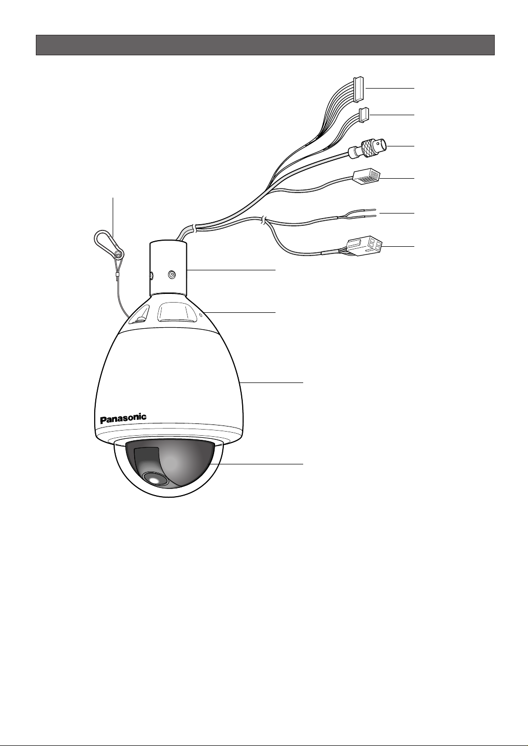
CONSTRUCTION
q Alarm Input Connector
w Alarm Output Connector
e Video Output Connector
r Data Port
t Power Cord for Heater
y Power Connector for Camera
u Attachment Pipe
i Upper Base
o Fall Prevention Wire
!0 Enclosure
!1 Dome
-9-
o
q
w
e
r
t
y
u
i
!0
!1

SETUP
■ Setup Menu
Setup menus are shown in the diagram below. You can adapt the camera to your requirements by setting up the
respective items in these menus. Menus are incorporated in a hierarchical structure, from the setup menu at the top
to manual mask area selection at the bottom. These menus are described on the following pages for reference.
Switches, keys and the joystick are used in the setup operations.
-10-
Setup Menu
Preset Menu (P. 18)
Map Menu
Home Position Setting (P. 23)
Self Return Setting (P. 23)
Auto Mode Selection (P. 23)
Auto Pan Key Setting (P. 25)
Special 1 Menu (P. 27)
Digital Flip Setting (P. 25)
Camera Menu (P. 34)
Camera ID Editing (P. 34)
Light Control Setting (P. 35)
Shutter Speed Setting (P. 36)
AGC Mode Selection (P. 36)
Electronic Sensitivity
Enhancement (P. 36)
Synchronization (P. 37)
White Balance (P. 38)
Motion Detector (P. 39)
Auto Focus Setting (P. 40)
Special 2 Menu (P. 40)
RS-485 Setup (P. 43)
Password Lock (P. 26)
Preset No.Setting (P. 18)
Preset Setting Menu
(P. 18)
Auto Pan Setting (P. 25)
INT Manual Selection (P. 37)
LL Manual Selection (P. 37)
VD2 Automatic Selection
(P. 37)
Manual Level Adjustment
(ATW1, ATW2) (P. 38)
Manual Level Adjustment
(AWC) (P. 38)
Sensitivity Level Adjustment
(P. 39)
Manual Mask Area
Selection (P. 35)
Camera ID Display Position
(P. 34)
ALC Mode with Super-D2 ON
(P. 35)
V-phase Manual
Adjustment (P. 37)
Privacy Zone ON/OFF
(P. 27)
Proportional Pan/Tilt
(P. 28)
Area Title (P. 28)
Patrol Learn (P. 30)
Alarm IN/OUT (P. 31)
Cleaning (P. 32)
Electric Zoom (P. 32)
Preset Alarm (P. 33)
Image Hold (P. 33)
Tilt Angle (P. 33)
Mask Area Selection
(P. 39)
Demonstration Display
Password Registration
(P. 26)
Password Verification (P. 26)
ALC Mode with Super-D2
OFF (P. 35)

-11-
Position Setting (P. 18)
Dwell Time Setting (P. 21)
Chroma Level Setting (P. 40)
Aperture Level Setting (P. 40)
Pedestal Level Setting (P. 40)
Resolution (P. 40)
Digital Noise Reduction
(P. 41)
BW Mode (P. 41)
PIX OFF Setting (P. 42)
Super-D2 OFF (P. 35)
Preset ID Editing (P. 18)
Super-D2 ON (P. 35)
Manual Iris Adjustment (P. 35)
Shutter Speed (P. 36)
Gain Control (P. 36)
Electronic Sensitivity
Enhancement (P. 36)
White Balance (P. 38)
Motion Detector (P. 39)
Auto Focus (P. 40)
Unit Number (P. 43)
Sub Address (P. 43)
Baud Rate (P. 43)
Data Bit (P. 43)
Parity Check (P. 43)
Stop Bit (P. 43)
X On/X Off (P. 43)
Wait Time (P. 43)
Alarm Data (P. 43)
Delay Time (P. 43)
Light Control Setting (P. 21)
To Restore the Camera Default
Position (P. 42)
Camera Resetting (P. 42)
Zone Number Selection (P. 27)
Zone Parameter Setting
(P. 27)
Setting for ON (USER) (P. 29)
Setting for ON (NESW) (P. 28)
Area Title Display (P. 29)
Learning Display (P. 30)
Alarm IN/OUT Setting (P. 31)
Cleaning Display (P. 32)
Scene File Setting (P. 21)
Preset Speed (P. 22)
B/W AUTO/ON/OFF (P. 41)
B/W Auto Sensitivity Level
(P. 41)
B/W Auto Duration Time Setting
(P. 41)
Pixel SENS UP (P. 41)
Burst (BW) Setting (P. 41)
Manual Level Adjustment
(Contrast) (P. 36)
Manual Mask Area Selection
(P. 35)
Manual Level Adjustment
(ATW1, ATW2) (P. 38)
Sensitivity Level Adjustment
(P. 39)
Mask Area Selection (P. 39)
Demonstration Display
Manual Level Adjustment
(AWC) (P. 38)
Preset Identification Setting
(P. 20)
-12-
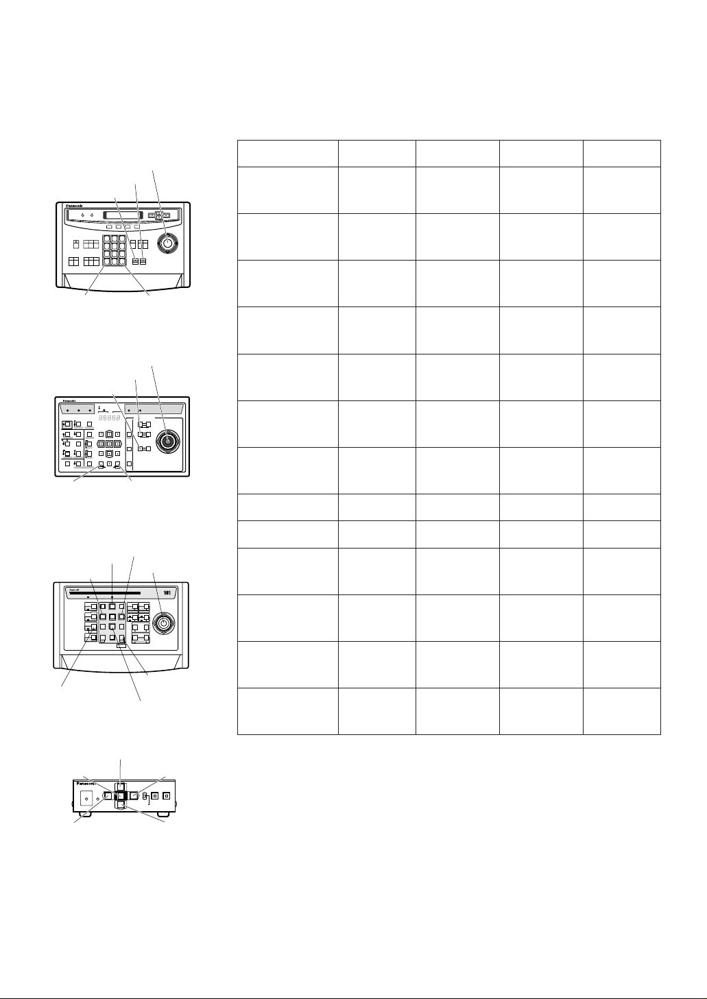
The keys (switches) to be used for setup are shown in the table below. The joystick on the connected controller may
also be used for setup. The table also shows the functions and the operations of the individual controllers. For details,
see the manual for the controller to be used. Switches and controls are abbreviated as SW and CTRL respectively in
the table.
Notes:
•A changed parameter is entered only when you move the cursor to another
item or open a new menu. If you close the setup menu without either of the
above actions, the changed parameter will not be entered.
• Setting procedures on the following pages are described on the assumption
that the camera is used with WJ-SX550C Matrix Switcher and WV-CU550C/CJ
System Controller.
Open Special 2 F2 key
Function/Controller
WV-CU550C/CJ WV-CU360C/CJ
WV-CU161C WV-RM70
Open CAM SETUP See page 17
CAM SETUP
key (for 2 seconds or more)
CAMERA SETUP
key (for 2 seconds or more)
See page 17
Close CAM SETUP F4 key
CAM SETUP
key (for 2 seconds or more)
CAMERA SETUP
key (for 2 seconds or more)
PROG SW
Move the cursor
Joystick
(
←, ↑, ↓, →)
Joystick
(←, ↑, ↓, →)
Direction SW
(←, ↑, ↓, →)
Direction SW
(←, ↑, ↓, →)
Select a parameter
Joystick
(
←, →)
Joystick
(←, →)
Direction SW
(←, →)
Direction SW
(←, →)
Adjust the level
Joystick
(
←, →)
Joystick
(←, →)
Direction SW
(←, →)
Direction SW
(←, →)
Move the camera
direction
Joystick
(
←, ↑, ↓, →)
Joystick
(←, ↑, ↓, →)
Joystick
(←, ↑, ↓, →)
Direction SW
(←, ↑, ↓, →)
Zoom & Focus
ZOOM CTRL &
FOCUS CTRL
ZOOM CTRL &
FOCUS CTRL
ZOOM CTRL &
FOCUS CTRL
Direction SW
(
←, ↑, ↓, →)
Enter the setting CAM (SET) key CAM (SET) key CAM (SET) key SET SW
Open a submenu CAM (SET) key CAM (SET) key CAM (SET) key SET SW
Enter CAM ID &
PRESET ID
display position
MON (ESC) key MON (ESC) key SET key
SET SW
(for 2 seconds)
Enter MASK
setting
MON (ESC) key MON (ESC) key SET key
SET SW
(for 2 seconds)
All Reset F3 key
4+5+6 key
(for 2 seconds
or more)
4+5+6 key
(for 2 seconds
or more)
R+SET+L SW
(for 2 seconds)
4+6 key
(for 2 seconds
or more)
4+6 key
(for 2 seconds
or more)
R+L SW
(for 2 seconds)
OPERATELOGIN ALARM
FUNCTION
SX
IRIS
CLOSE OPEN
NEAR FAR
WIDE TELE
FOCUS
ZOOM
AUTO FOCUS
IRIS RESET
HOME
SET UP
ALM RECALL
CAM SETUP
CAM FUNCTION
MULTI SCREEN
DEF
WIPER
EL-ZOOM
SHIFT
ALM RESET
VTR CAM
STILL
-1 CAM/DEC
ALM SUSPEND
+1 CAM/INC
PATROLSTOP
AUX 1
AUX 2
B/W UNIT
SEQ PAUSE
BOOST
SEQUENCE AUTO
PRESET
POSI
FS
MON
CAM
LOGOUT
ESC SET
CAMERA SITE CONTROL
UP
LR
DOWN
BUSY PROHIBITED
MONITOR
UNIT
CAMERA
System Controller
WV-CU
360
1 2 3
4 5 6
7 8 9
MON CAM
ESC SET
0
ACK
RESET
BACK
SEQ
FORWARD
SEQ ALT
DEC
–1CAM
INC
+1CAM STOP
12
AUX
CLOSE OPEN
IRIS
PRESET
FOCUS
NEAR
ZOOM
TELE
FARWIDE
System Controller WV-CU550C
LEFT RIGHT
UP
DOWN
ALARM BUSY
F3 F4F2F1
AF
[WV-CU550C/CJ]
[WV-CU161C]
[WV-RM70]
Joystick
CAM (SET)
Key
MON (ESC)
Key
CAM (SET)
Key
MON (ESC)
Key
SET Key
CAM (SET) Key
OPERATE
REMOTE
NORMAL PROG
ALARM
RESET
SYSTEM
ALARM OFF
Camera Controller WV-RM
7070
Up Switch
Set Switch
Right
Switch
Left Switch Down
Switch
[WV-CU360C/CJ]
Joystick
Joystick
FOCUS Switch
ZOOM Switch
FOCUS Switch
ZOOM Switch
Up Switch
R
System Controller WV-CU
1 2 3
4 6
7 8 9
0
5
SHIFT
OPERATE ALARM
RESET
RESET
SUSPEND
CAMERA
SETUP
PATROL
PAY
PROGRAM
PRESET
CAMERA
FUNCTION
SERUP
ESC
HOME
SET
PRESET
WIDE TELE
NEAR
AUX1
B/W
AUTO
WIPER
AUX2
DEF
UP
DOWN
L
FAR
FOCUS
IRIS
CLOSS OPEN
PROGRAM
ALARM
IRIS RESET
AUTO FOCUS
Left Switch
Right Switch
Down Switch

-13-
■ Setup Menu Description
● Presetting
(1) Position (POSITION SET)
Aligns the camera position and focal point by panning, tilting, zooming and focusing.
See page 18 for the setting.
(2) Preset Identification (PRESET ID)
Assigns the name for preset IDs (identification of up
to 16 alphanumeric characters) and can be
switched on or off on the monitor screen.
See page 20 for the setting.
(3) Light Control (ALC/MANUAL)
Selects the ALC or MANUAL mode for adjusting the
lens iris.
See page 21 for the setting.
(4) Dwell Time (DWELL TIME)
Displays the picture at each camera position for the
selected duration.
You can select a preset duration from the menu.
See page 21 for the setting.
(5) Scene File (SCENE FILE)
Stores up to 10 files.
Each file has a set of detailed parameters for the
shutter speed, AGC, electronic sensitivity enhancement, white balance, motion detector and AF mode.
The scene files can be recalled later to reproduce
the parameter settings under the same conditions
as stored in the files.
See page 21 for the setting.
● Home Position (HOME POSITION)
The home position is the camera’s basic position.
The camera returns to this position automatically after a
specific time following a manual operation. This setting
functions only when AUTO MODE is OFF.
See page 23 for the setting.
● Self Return (SELF RETURN)
The self return function allows the camera to resume
one of the operations described below after specified
time.
This function automatically works after a lapse of setting
time from manual operation finished.
OFF: Cancels the auto mode (SEQ, SORT, AUTO PAN
and PATROL).
AT (the auto mode is set to OFF): Shifts the camera
direction to the home position.
AT (the auto mode is set to other than OFF):
Activates the auto mode.
HP: Shifts the camera direction to the home position.
AP: Starts the auto pan function.
SQ: Starts the sequence function.
SR: Starts the sort function.
PT: Starts the patrol function.
See page 23 for the setting.
● Auto Mode (AUTO MODE)
The auto mode is used for setting the movement of the
camera.
You can select one of four automatic operation modes
and one manual operation mode as follows:
OFF: No automatic operation. The camera can be oper-
ated only manually.
SEQ: The camera operates in the sequence of preset
positions in numerical order.
SORT: The camera operates in the sequence of preset
positions counterclockwise from pan starting point.
AUTO PAN: The camera automatically turns within the
preset panning range.
PATROL: The camera operates in the patrol-learn func-
tion.
See page 30 for the setting.
● Auto Pan Key (AUTO PAN KEY)
This setting assigns the SEQ, SORT, AUTO PAN or
PATROL (PLAY) mode to the AUTO key on the controller.
After this setting, the AUTO key performs as assigned.
Note: The AUTO PAN LED on the controller does not
light if a mode other than AUTO PAN is assigned.
● Digital Flip (DIGITAL FLIP)
Tilt range is limited within 0 ° to 90 ° if OFF is selected.
If ON is selected it widens the range up to 180 ° with
the digital flip that reverses horizontal and vertical scanning when the camera is tilted beyond 90 ° point
(Downright position if the camera is installed on a ceiling). Tilt range narrows from 0 ° to 90 ° if PAN LIMIT is
set to ON.
● Password Lock (PASSWORD LOCK)
This menu limits setting changes.
● Special 1 Menu
(1) Privacy Zone (PRIVACY ZONE)
This setting is used for masking unwanted zones,
hiding them from display on the monitor screen.
Up to 8 zones can be registered. Submenus are
provided for zone number selection and parameter
setting. See page 27 for details.

-14-
(2) Proportional Pan-Tilt Speed (PROPO. P/T)
If ON is selected, the pan-tilt speed changes automatically corresponding to the zoom ratio. For
example, the pan-tilt speed slows down when the
camera zooms in. See page 28 for details.
(3) Area Title (AREA TITLE)
Up to 8 area titles can be assigned to specific
scenes on the DIRECTION (NESW) menu or by
alphanumeric (USER) assignment. The area title is
displayed under the camera ID on the monitor
screen when the camera turns to a position that has
been assigned an area title. See page 28 for details.
(4) Patrol-learn and Patrol Play (PATROL)
A set of manual operations is stored (LEARN), reproduced (PLAY) or turned inactive (OFF). Patrol operation stops if SEQ, SORT or AUTO PAN is set to
AUTO MODE on the SETUP menu. See page 30 for
details.
(5) Alarm Input/Output (ALARM IN/OUT)
Alarm input and output are set on a submenu.
Preset positions are assigned to ALARM IN 1 to 4.
When alarm inputs are supplied via the alarm input
connector, the camera turns to the respective positions. Then the camera sends output signals via the
alarm output connector or the coaxial cable to the
external devices. The B/W mode may be chosen if
light is insufficient. CNT-CLS (Contact Closure) 1, 2
and COAX ALM OUT are used for alarm output setting. See page 31 for details.
(6) Cleaning (CLEANING)
This is used for refreshing the electric-mechanical
contacts built in the camera. Use this function for
maintenance when the camera has been directed at
a specific spot or panned over a specific range for a
long time.
(7) Electronic Zoom (EL-ZOOM)
Up to 10-fold electronic zooming is available
besides 22-fold optical zooming.
(8) Preset Alarm (PRESET ALM)
Alarm signals are generated in the following cases if
ON is selected.
• When a preset positioning sequence is completed
while AUTO MODE is set to SEQ.
• When a preset positioning sequence is completed
while AUTO MODE is set to SORT.
• Positioning is completed at the HOME position in the
SELF RETURN mode.
• Positioning is completed in the ALARM IN mode.
• When positioning to the starting point is completed
while AUTO MODE is set to AUTO PAN.
• When positioning to the starting point is completed
while PATROL is set to PLAY.
(9) Image Hold (IMAGE HOLD)
The camera picture remains as a still image on the
monitor screen or until the camera reaches the preset position. This function is useful for surveillance
via a local area network.
(10)
Tilt Angle 0 °/5 °
You can select a titling range. If 5 ° is selected, the
tilting angle is adjustable up to 5 ° beyond the horizontal position.
● Camera
(1) Camera Identification (CAMERA ID)
You can use the camera identification to assign a
name to the camera. The camera ID consists of up
to 16 alphanumeric characters. You can select
whether to have the camera ID displayed on the
monitor screen or not. See page 34 for the setting.
(2) Light Control (ALC/MANUAL)
You can select a mode for adjusting the lens iris.
There are two modes as follows:
ALC: The lens iris is automatically adjusted accord-
ing to the brightness of an object.
You can select one of two modes (SUPER-D2
ON or SUPER-D2 OFF) of backlight compensation.
Backlight compensation is available in the ALC
mode. It eliminates strong background light
which makes the camera picture dark such as a
spotlight.
MANUAL: The lens iris is fixed at the value that you
have set regardless of the brightness of an
object.
• ALC Mode with SUPER-D2 ON
Super-Dynamic 2 Function (SUPER-D2)
The important object in a scene is usually placed in
the center of the monitor’s screen. In the SUPER-D2
mode, photometric weight is given more to the center of the screen (where the important object is
located) than to the edge of the picture (where a
bright backlight would most likely to be located).
You can use the SUPER-D2 function if you select
ALC. The function eliminates interference by strong
background lighting which makes the camera picture dark, such as a spotlight.
See page 35 for the setting.
• ALC Mode with SUPER-D2 OFF
In this mode, the picture is divided into 48 areas. If
there is a source of brightness that interferes with
the clarity of the picture in these masks, corresponding areas mask the light to keep the clarity of the
picture.

-15-
Generally, when a light from the background is too
strong such as a spotlight, all objects except the
main object in the picture are displayed darker
because the lens iris is adjusted with respect to
strong brightness. This model ignores strong brightness by masking the source of the strong brightness, thereby the main object is displayed clearly.
Notes:
• The result of field setup of the mask area and level
adjustment is fed back (effected) to the lens iris control in the ALC mode.
• Select OFF for SUPER-D2 on the ALC CONT menu
when using only for the outdoors.
If ON is selected for the SUPER-D2 parameter, a
shadow (black line) may appear at the boundary
between the bright and the dim scenes. This is a
natural phenomenon and does not indicate trouble.
(3) Shutter Speed (SHUTTER)
You can select a shutter speed from among 1/60
(OFF), AUTO, 1/100, 1/250, 1/500, 1/1 000,
1/2 000, 1/4 000, and 1/10 000 seconds.
See page 36 for the setting.
(4) Gain Control (AGC)
You can set the gain of an image to automatic
adjustment [AGC ON (LOW, MID, HIGH)] or fixed
(AGC OFF).
See page 36 for the setting.
(5) Electronic Sensitivity Enhancement (SENS UP)
The electronic sensitivity enhancement function
varies the shutter speed to increase the sensitivity in
low light conditions.
You can select either of the following shutter speeds
for SENS UP.
1/25 seconds (x2), 1/12.5 seconds (x4), 1/8.3 seconds (x6), 1/5 seconds (x10), 1/3.1 seconds (x16) or
1/1.6 seconds (x32).
See pages 36 for the setting.
There are two modes for SENS UP as follows:
AUTO: If you select x32, the sensitivity is increased
automatically up to x32.
FIX: If you select x32, the sensitivity is increased to
a fixed x32.
Notes:
• Moving objects will appear blurred when shot in the
electronic sensitivity enhancement mode since
SENS UP is equivalent to reducing the shutter
speed in a still picture camera.
• The horizontal and vertical resolution will be lowered
in this mode.
• If the iris opening is too small, the SENS UP/AUTO
mode will not function.
(6) Synchronization (SYNC)
You can select the internal sync (INT) mode or the
line-lock sync (LL) mode. Additionally, this model
accepts the VD2 signal from a specified component.
Whenever the VD2 signal is supplied to this camera,
the camera automatically switches to the VD2 sync
mode.
When you select the line-lock (LL) mode, you can
adjust vertical phase.
See page 37 for the setting.
Important Notices:
The priorities of sync modes are assigned as follows:
1. Multiplexed vertical drive (VD2) (highest)
2. Line-lock (LL)
3. Internal sync (INT) (lowest)
Note: The priorities of the automatic sync modes are
the same as the above.
(7) White Balance (WHITE BAL)
You can select either of three modes shown below
for white balance adjustment:
• Auto-Tracing White Balance (ATW1)
In this mode, the color temperature is monitored
continuously and thereby white balance is set automatically. The color temperature range for the proper white balance is between approx.
2 700 and 6 000 K. Proper white balance may not
be obtained under the following conditions:
1. When the color temperature is out of the range of
2 700 - 6 000 K.
2. When the scene contains mostly high color temperature (bluish) objects, such as a blue sky.
3. When the scene is dim.
In these cases, select the AWC mode.
• Auto-Tracing White Balance (ATW2)
This mode enables the camera to trace the white
balance when it is used in an area lit by sodium
lamps.
• Automatic White Balance Control (AWC)
In this mode, accurate white balance is obtained
within a color temperature range of approx. 2 300 10 000 K.
See page 38 for the setting.
(8) Motion Detector (MOTION DET)
The motion detector detects motion in a scene by
monitoring changes in the brightness level. You can
select the sensitivity level for the motion on the setup
menu.
When the camera detects motion, it sends an alarm
signal to the external equipment and stops at its
position for the preset dwell time.
See page 39 for the setting.

-16-
(9) Auto Focus (AF MODE)
The camera adjusts the focus automatically by sensing the center of the picture. S, M and L stand for
the size of the sensing area: Small, Middle and
Large.
See page 40 for details.
MANUAL S, M, L: Auto-focus is activated only when
the AF key on the controller is pressed.
AUTO S, M, L: Auto-focus is activated automatically
while a manual pan, tilt or zoom operation is performed.
Note: If SENS UP is set to ON except x2 FIX or x2
AUTO, the AUTO (S/M/L) mode is disabled and
the MANUAL (S/M/L) mode is automatically
selected.
(10)
Special 2 Menu (SPECIAL2)
This menu allows you to adjust and set up the following items and functions: chroma level, aperture
level and pedestal level.
You can also reset your parameters to the factory
default settings.
See page 40 for the setting.
(11)
Self-diagnosis Function
If the camera continues operating abnormally for 30
seconds or more due to such accident as external
noise, the camera will automatically reset its power.
In the case it happens frequently, check if there
would be any environmental cause.
● RS485 Communication
Refer to the following pages for the communication
parameter settings.
• Full/Half duplex (page 45)
• Transmission speed (4 900 - 19 200 bps) (page 45)
• Parity bit, Stop bit, Flow control (page 43)
• Wait time, Delay time, Alarm output (page 43)
• Camera units (96 units max.) (page 43)
• Termination ON/OFF (page 43)
• Reset parameters (page 43)

SETTING PROCEDURES
The following setting procedures are described on the
assumption that this model is used in combination with
WJ-SX550C Matrix Switcher and WV-CU550C/CJ
System Controller. In case a controller other than WVCU550C is used, refer to the table on page 12.
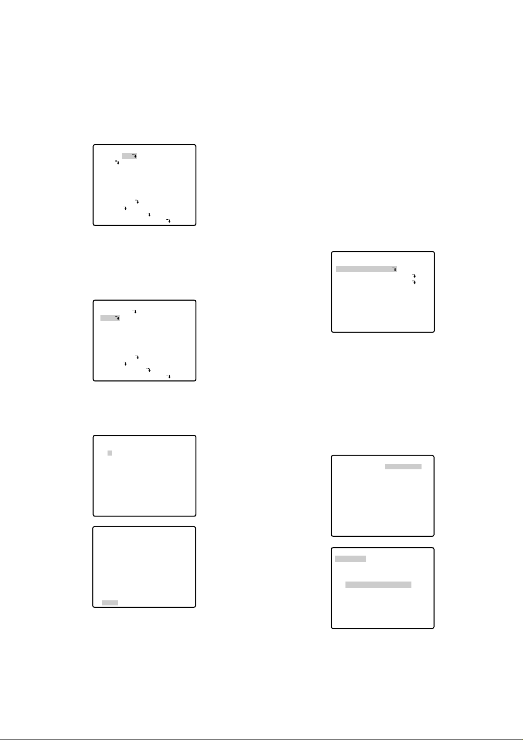
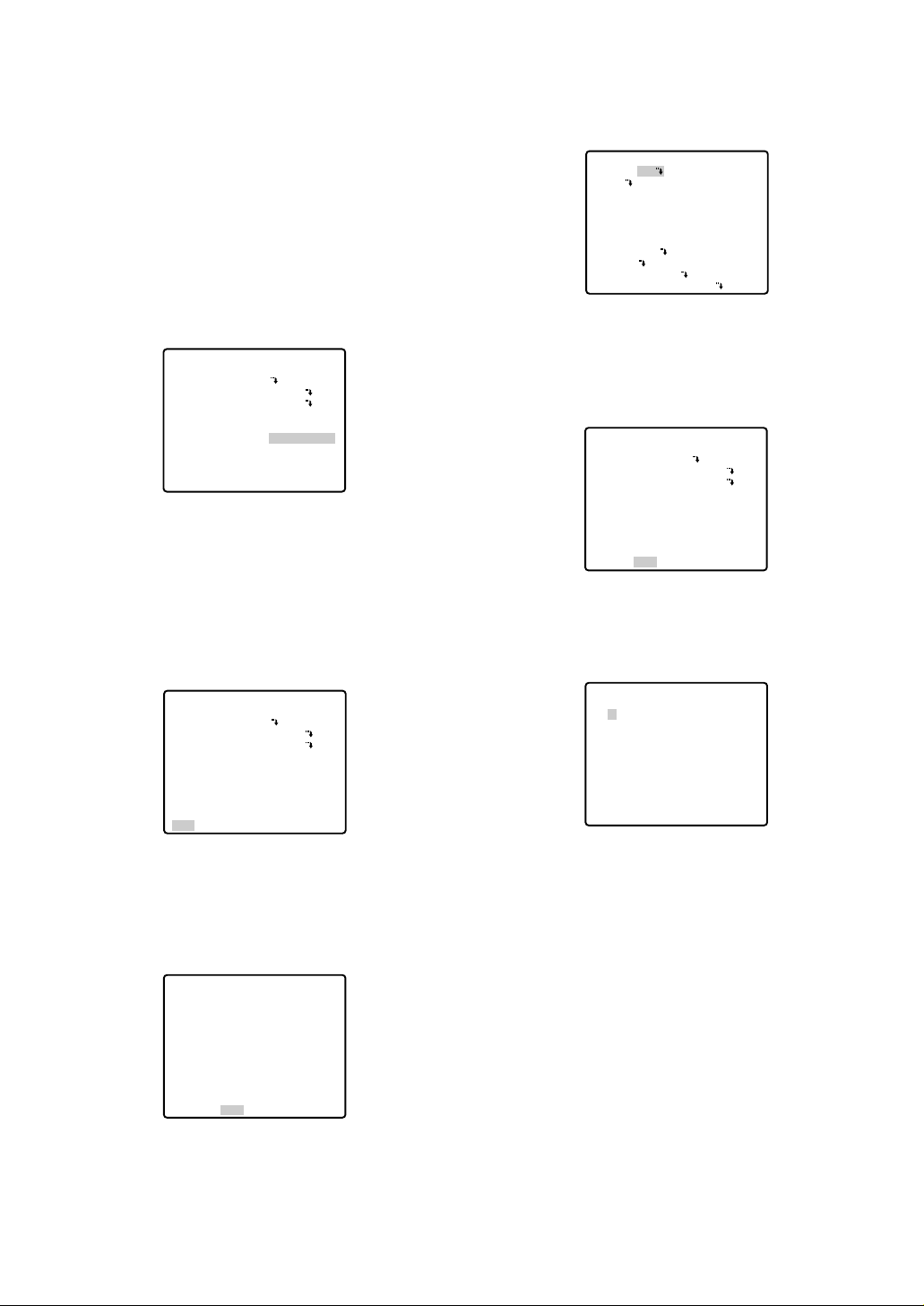
■ Menu Display
● Setup Menu Display
WV-CU550C/CJ
1. Select the number of the camera you want to set up
and a monitor to display SET UP MENU.
2. Display the D4 menu on the LCD by pressing the
appropriate direction buttons.
3. Press the F1 button.
SET UP MENU appears on the monitor.
4. To close SET UP MENU, press the F4 button.
WV-CU360C/CJ
Press the CAM SETUP key for 2 seconds or more to
open the SETUP menu.
WV-CU161C
Press the CAMERA SETUP key for 2 seconds or
more to open the SETUP menu.
WV-RM70
1. Turn the MODE SELECTION switch to the NORMAL
or ALARM OFF position.
2. Press the PROG switch for 2 seconds or more to
open the Program menu.
3. Move the cursor to Camera Set Up Menu, and press
the SET switch to open SETUP MENU.
● Submenu Display
The items marked O can be selected/changed on the
submenu.
• Move the cursor to an item with the O mark and
press the CAM (SET) key. The submenu appears.
-17-
Camera Set Up Menu
On Exit
F2 F3 F4
F1
Camera Set Up Menu
Res A.Res Exit
F1 F2 F3 F4
** RS485 SET UP **
UNIT NUMBER
SUB ADDRESS
BAUD RATE
DATA BIT
PARITY CHECK
STOP BIT
XON/XOFF
WAIT TIME
ALARM DATA
DELAY TIME
RET
1
----19200
8
NONE
1
NOT USE
OFF
AUTO2
---
** SET UP MENU **
PRESET 1
MAP
HOME POSITION
SELF RETURN
AUTO MODE
AUTO PAN KEY
DIGITAL FLIP
SPECIAL1
CAMERA
RS485 SET UP
PASSWORD LOCK OFF
OFF
OFF
OFF
AUTO PAN
ON
-18-
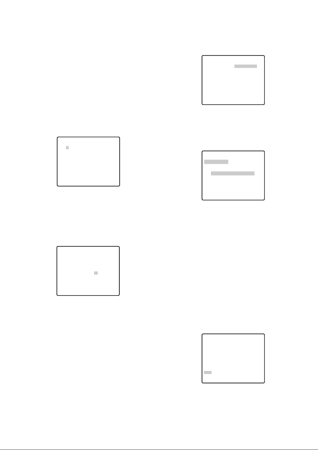
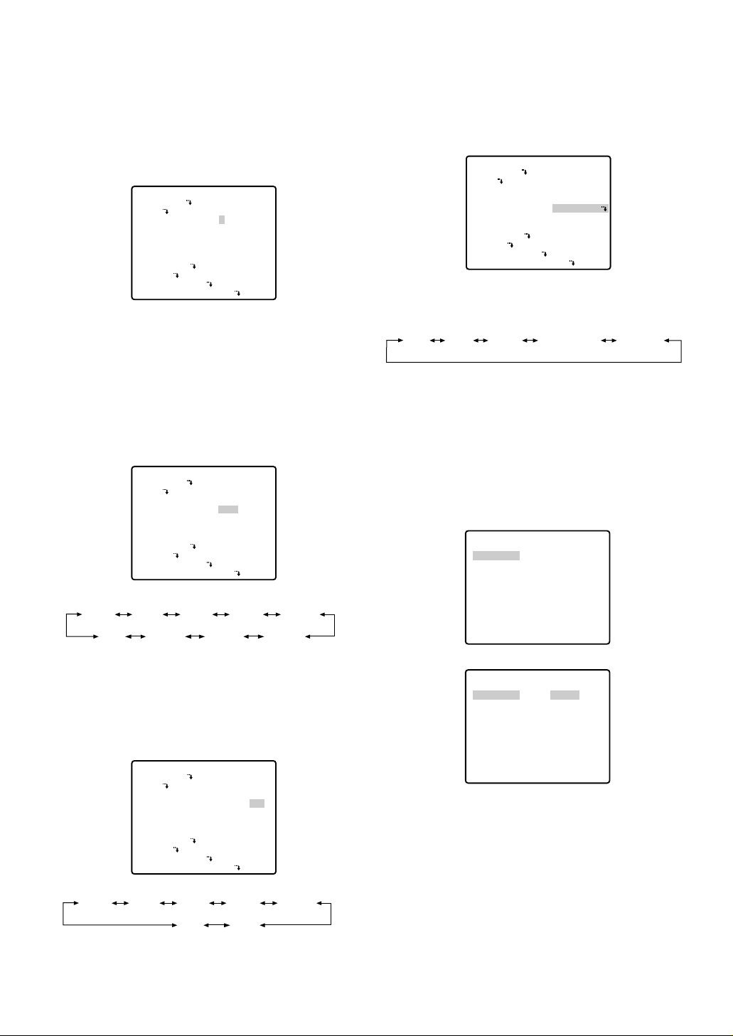
■ Preset Menu
● Preset Menu Display
1. Displaying the preset menu directly
(1) Move the cursor to PRESET 1
O and select the
position number with the joystick.
(2) Press the CAM (SET) key.
The preset setting menu appears on the monitor
screen.
2. Displaying the preset menu from the PRESET NUM-
BER SET menu
(1) Move the cursor to MAP
O and press the CAM
(SET) key.
The PRESET NUMBER SET menu appears on the
monitor screen.
(2) Move the cursor to the position number to be set
and press the CAM (SET) key.
The preset setting menu appears on the monitor
screen. To display any position number between 33
and 64, move the cursor to "33-64" in the lower left of
the screen and press the CAM (SET) key.
Notes:
• The * mark indicates that the position number
has been preset.
• The character H refers to the home position.
• The second line from the bottom shows the preset ID corresponding to the selected number.
"DOOR" next to "ID" in the example shown right is
for preset position number 1.
• Preset numbers 1 to 4 are linked to alarm inputs
1 to 4 respectively. If alarm input 1 comes in, the
camera turns to preset position 1, and to other
positions according to alarm input 2, 3 or 4.
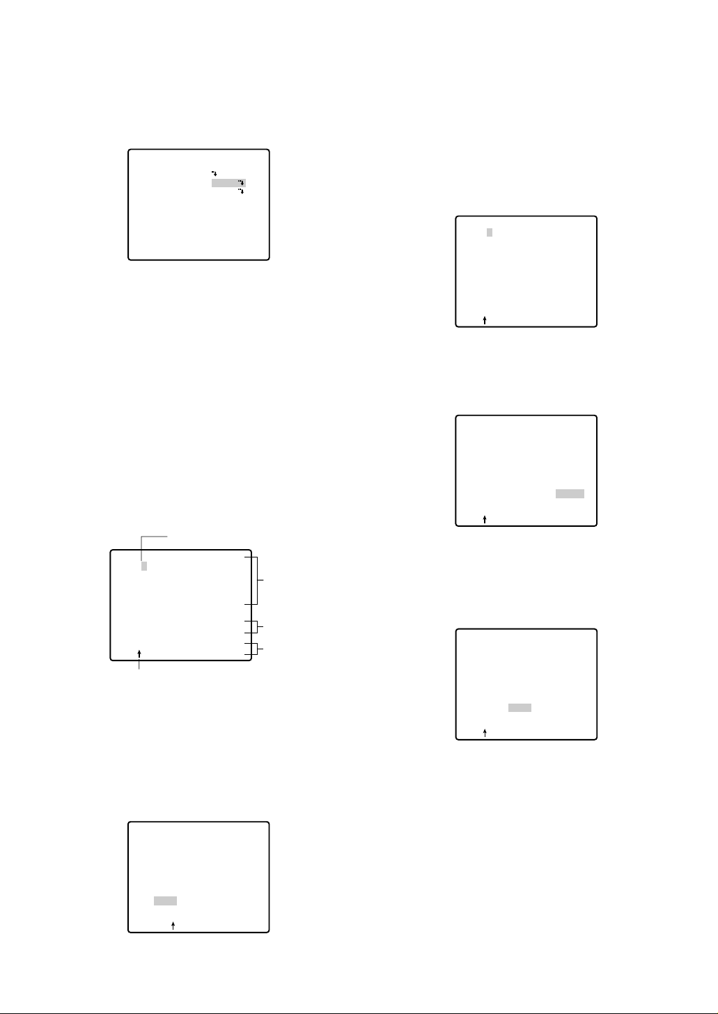
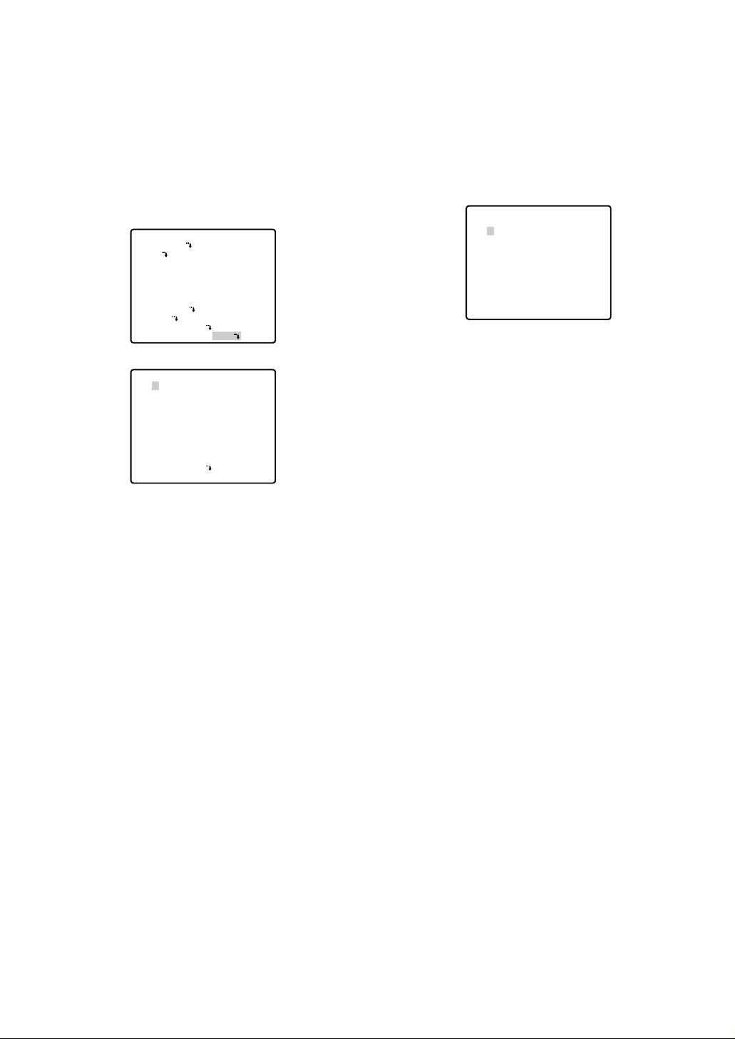
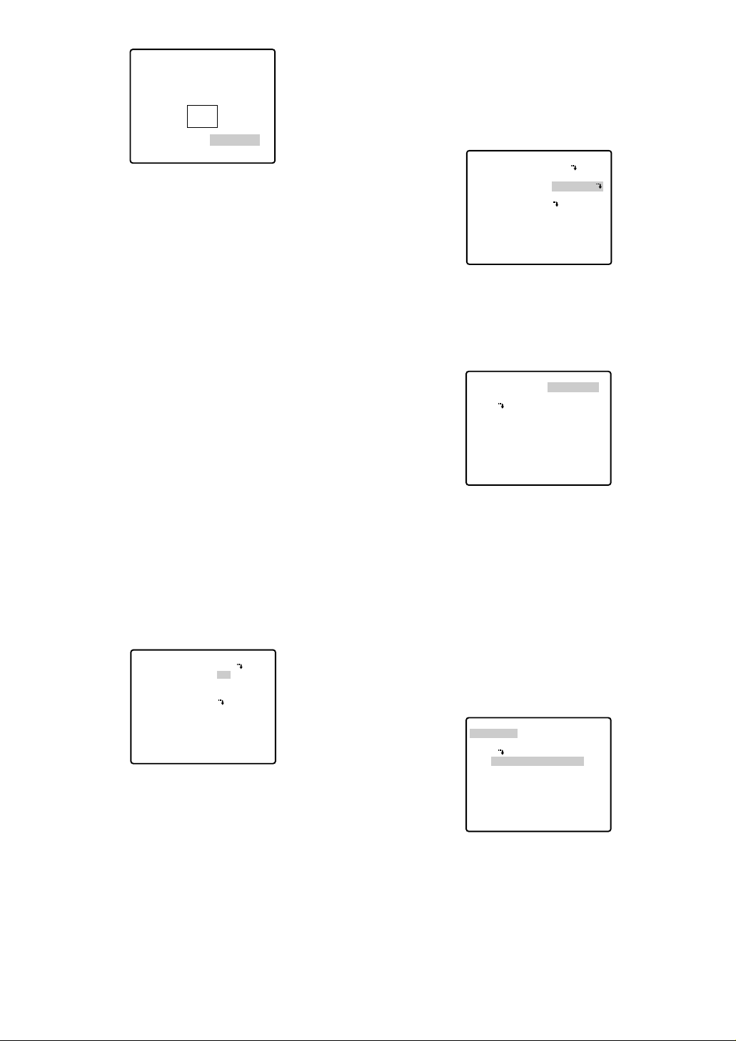
● Position Setting (POSITION SET)
1. Move the cursor to POSITION SET on the preset set-
ting menu and press the CAM (SET) key.
The position setting menu appears.
2. To Set Panning/Tilting Positions
(1) For PAN/TILT, move the cursor to PUSH SET and
press the CAM (SET) key. The PAN/TILT setting
menu appears.
(2) Select panning/tilting positions with the joystick, and
press the CAM (SET) key.
The positions are set and the screen returns to the
position setting menu.
** SET UP MENU **
PRESET 1
MAP
HOME POSITION
SELF RETURN
AUTO MODE
AUTO PAN KEY
DIGITAL FLIP
SPECIAL1
CAMERA
RS485 SET UP
PASSWORD LOCK OFF
** SET UP MENU **
PRESET 1
MAP
HOME POSITION
SELF RETURN
AUTO MODE
AUTO PAN KEY
DIGITAL FLIP
SPECIAL1
CAMERA
RS485 SET UP
PASSWORD LOCK OFF
** PRESET NUMBER SET **
2
1
6
5
10
9
14
13
18
17
22
21
26
25
30
29
ID:
33-64 RET
** PRESET NUMBER SET **
34
33
37
41
45
49
53
57
61
1-32 RET
38
42
46
50
54
58
62
35
39
43
47
51
55
59
63
OFF
OFF
OFF
AUTO PAN
ON
OFF
OFF
OFF
AUTO PAN
ON
3
4
7
8
11
12
15
16
19
20
23
24
27
28
31
32
36
40
44
48
52
56
60
64
PRESET NO. 1
POSITION SET
PRESET ID
ALC/MANUAL
DWELL TIME
SCENE FILE
PRESET SPEED
RET DEL
** POSITION 1 **
PAN/TILT
ZOOM/FOCUS
PAN OFFSET SET
RET
** POSITION 1 **
PAN/TILT
ZOOM/FOCUS
U TILT D/L PAN R
PAN OFFSET SET
RET
ON
ALC
10S
1
••••••••|
L H
→
PUSH SET
→
PUSH SET
← 0 →
→
PUSH SET
→
PUSH SET
← 0 →
-19-
3. Pan Offset
If the camera is replaced with a new one, the pan
offset function is used to adjust its positions to be
the same as before except patrol setting.
The system controller can download or upload the
preset position data.
Caution: The preset data for other cameras (WV-
CW654 for example) is incompatible with WVCW864A’s. WV-CW864A’s preset data will be
destroyed if you upload the conventional data. If
this happened, reset the WV-CW864A to the
default settings. Download the factory settings
into the controller and upload the correct preset
data newly to the initialized WV-CW864A.
(1) Display the PRESET NUMBER SET menu.
(2) Select a position number for the picture to be most
enlarged among the numbers with the joystick. Then
press the CAM (SET) key. The position setting menu
appears.
(3) Move the cursor to PAN OFFSET SET and select the
right or left arrow with the joystick.
(4) Press the CAM (SET) key until the desired offset
value appears.
(5) Move the cursor to an item other than PAN OFFSET
SET, and press the MON (ESC) key.
Notes:
• Further adjustment of the other positions is
unnecessary. This adjustment applies to all other
positions.
• Make sure to move the cursor before pressing
the key in step 5. Otherwise the settings will be
ignored.
• Retry the loading when the camera fails to
upload or download the data.
4. To Set the Lens Zoom and Focus Positions
(1) Move the cursor to PUSH SET for ZOOM/FOCUS
and press the CAM (SET) key. The ZOOM/FOCUS
setting menu appears.
(2) Select a zoom position by moving the zoom control
up and down and a focus position by moving the
focus control up and down, and then press the CAM
(SET) key.
The positions are set and the screen returns to the
position setting menu.
Notes:
• When the camera is used at a nearly horizontal
angle, the focus may not be adjustable to a high
level of accuracy.
• If you move the cursor to the position number
and move the joystick right or left, the position
number can be selected.
The selected preset position number can also be
set after pressing the CAM (SET) key.
• The preset and camera IDs appear in the lowerleft corner of the position setting menu after setting them.
5. Move the cursor to RET and press the CAM (SET)
key to return to the preset setting menu.
** PRESET NUMBER SET **
2
1*
5
9
13
17
21
25
29
ID:
33-64 RET
6
10
14
18
22
26
30
3
7
11
15
19
23
27
31
4
8
12
16
20
24
28
32
** POSITION 1***
PAN/TILT
ZOOM/FOCUS
PAN OFFSET SET
RET
→
PUSH SET
→
PUSH SET
← 0 →
** POSITION 1***
PAN/TILT
ZOOM/FOCUS
PAN OFFSET SET
RET
→
PUSH SET
→
PUSH SET
← 0 →
** POSITION 1***
PAN/TILT
ZOOM/FOCUS
U ZOOM D/L FOCUS R
PAN OFFSET SET ← 0
RET
→
PUSH SET
→
PUSH SET
→
** POSITION 1***
PAN/TILT
ZOOM/FOCUS
PAN OFFSET SET
RET
→
PUSH SET
→
PUSH SET
← 0 →
-20-
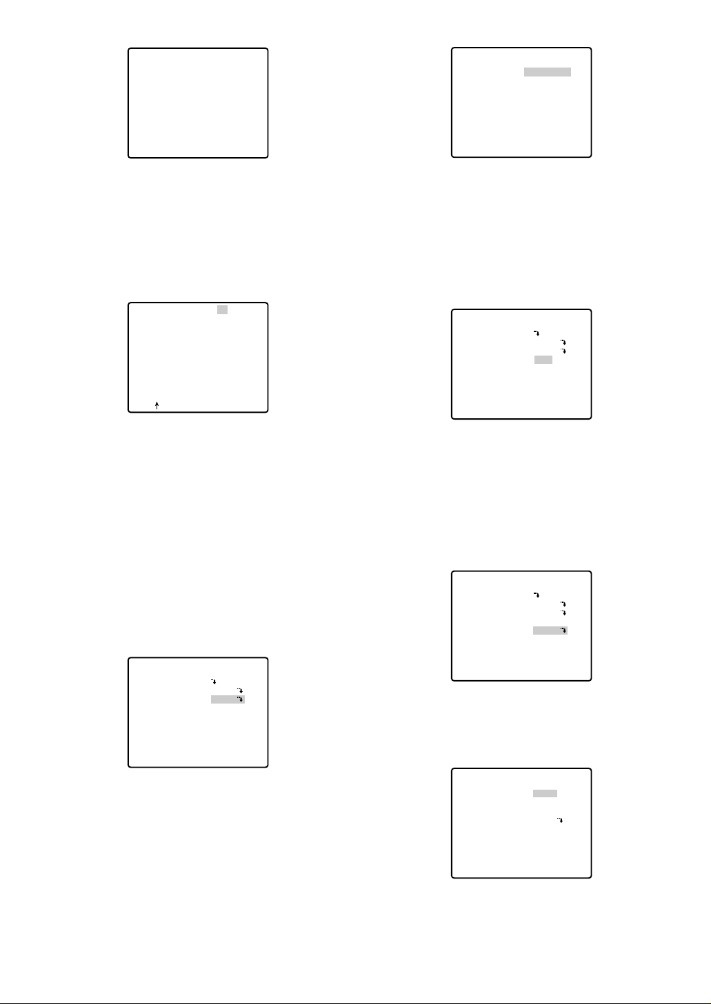
● Preset Identification Setting (PRESET
ID)
1. Move the cursor to PRESET ID on the preset setting
menu and select ON or OFF with the joystick.
The factory default setting is OFF.
ON: Preset ID appears on the monitor screen.
OFF: Preset ID does not appear.
2. Press the CAM (SET) key to display the preset ID
setting menu.
To Enter a New Preset ID
(1) Move the cursor to the desired character using
the joystick, and press the CAM (SET) key.
(2) The selected character appears in the editing
area. (The pointer in the editing area moves to
the right automatically at this moment.) To enter
a blank, select SPACE.
(3) Repeat the above procedure until all characters
are entered.
To Copy a Preset ID from Another Position
(1) Move the cursor to COPY and press the CAM
(SET) key. The preset ID in the preceding position is immediately shown. Each consecutive
pressing of the CAM (SET) key displays the ID
preceding the one currently displayed.
(2) Display the most prospective ID.
(3) Follow the step "To Change an Entered Preset
ID" if necessary.
To Change an Entered Preset ID
(1) Move the pointer to the character to be edited in
the editing area with the joystick.
(2) Select a new character with the joystick.
(3) Press the CAM (SET) key to determine the Preset
ID.
To Delete an Entered Preset ID
Move the cursor to RESET and press the CAM (SET)
key.
To Set a Display Position for a Preset ID
(1) Move the cursor to POSI and press the CAM
(SET) key. The display position set menu
appears.
(2) Move the ID to the desired position with the joy-
stick, and press the MON (ESC) key. The display
position is set and the monitor screen returns to
the preset ID setting menu.
PRESET NO. 1*
POSITION SET
PRESET ID
ALC/MANUAL
DWELL TIME
SCENE FILE
PRESET SPEED
RET DEL
Character Cursor
PRESET NO. 1*
0123456789
ABCDEFGHIJKLM
NOPQRSTUVWXYZ
().,'":;&#!?=
+-*/%$
SPACE
COPY POSI RET RESET
DOOR............
Pointer
PRESET NO. 1*
0123456789
ABCDEFGHIJKLM
NOPQRSTUVWXYZ
().,'":;&#!?=
+-*/%$
SPACE
COPY POSI RET RESET
DOOR............
ON
ALC
10S
1
••••••••|
L H
Character
Area
Command
Editing
Area
PRESET NO. 1*
0123456789
ABCDEFGHIJKLM
NOPQRSTUVWXYZ
().,'":;&#!?=
+-*/%$
SPACE
COPY POSI RET RESET
DOOR............
PRESET NO. 1*
0123456789
ABCDEFGHIJKLM
NOPQRSTUVWXYZ
().,'":;&#!?=
+-*/%$
SPACE
COPY POSI RET RESET
DOOR............
PRESET NO. 1*
0123456789
ABCDEFGHIJKLM
NOPQRSTUVWXYZ
().,'":;&#!?=
+-*/%$
SPACE
COPY POSI RET RESET
DOOR............
-21-
To Enter the Next ID without Returning to the
Preset Setting Menu
(1) In the preset ID setting menu, move the cursor to
the top line and select a desired position number
with the joystick.
(2) Enter, copy, change or delete the ID as
described above.
To Return to the Preset Setting Menu
Move the cursor to RET and press the CAM (SET)
key.
● Light Control Setting (ALC/MANUAL)
1. Move the cursor to ALC/MANUAL and select ALC or
MANUAL with the joystick.
The factory default setting is ALC.
ALC: The lens iris is automatically adjusted to suit
the brightness of the object.
MANUAL: The lens iris is fixed at the set value
regardless of the brightness of the object.
2. In case of ALC
O
Press the CAM (SET) key. The backlight compensation menu appears on the monitor screen. See page
33 for the setting.
3. In case of MANUAL
O
Press the CAM (SET) key. The setting menu appears
on the monitor screen. Set the lens iris level as
desired with the joystick.
● Dwell Time (DWELL TIME)
• Move the cursor to DWELL TIME and set a dwell
time with the joystick. The factory default setting is
10S. Dwell time changes as follows:
S stands for second(s), and MIN stands for
minute(s).
● Scene File Setting (SCENE FILE)
1. To set a scene file number
Move the cursor to SCENE FILE and select a scene
file number (1 to 10, or OFF) with the joystick. The
factory default setting is 1. No scene file is selected
at OFF.
2. To set scene file details
Move the cursor to a scene file number and press
the CAM (SET) key. The setting menu appears.
** MANUAL CONT **
IRIS
••••|••••
CLOSE OPEN
DOOR
PRESET NO. 1*
0123456789
ABCDEFGHIJKLM
NOPQRSTUVWXYZ
().,'":;&#!?=
+-*/%$
SPACE
COPY POSI RET RESET
DOOR............
PRESET NO. 1*
POSITION SET
PRESET ID
ALC/MANUAL
DWELL TIME
SCENE FILE
PRESET SPEED
RET DEL
ON
ALC
10S
1
••••••••|
L H
RET
PRESET NO. 1*
POSITION SET
PRESET ID
ALC/MANUAL
DWELL TIME
SCENE FILE
PRESET SPEED
RET DEL
ON
ALC
10S
1
••••••••|
L H
PRESET NO. 1*
POSITION SET
PRESET ID
ALC/MANUAL
DWELL TIME
SCENE FILE
PRESET SPEED
RET DEL
** SCENE FILE 1 **
SHUTTER
AGC
SENS UP
WHITE BAL
MOTION DET
AF MODE
ON
ALC
10S
1
••••••••|
L H
AUTO
ON(MID)
OFF
ATW1
1
MANUAL L
RET
-22-
See the pages below for the settings respectively.
Shutter speed: page 36
AGC: page 36
Electronic sensitivity enhancement: page 36
White balance: page 38
Motion detector: page 39
Auto focus: page 40
● Preset Speed Setting (PRESET
SPEED)
Move the cursor to PRESET SPEED and select a
speed with the joystick.
● To Return to the Preset Number Set
Menu
Move the cursor to RET and press the CAM (SET)
key. The PRESET NUMBER SET menu appears with
the * mark on the right of the preset position number.
● To Return to the Setup Menu
Move the cursor to RET and press the CAM (SET)
key.
■ Deleting Preset Positions
1. Move the cursor to PRESET 1 and select the position
number to be deleted with the joystick.
2. Press the CAM (SET) key to display the preset setting menu.
3. Move the cursor to DEL and press the CAM (SET)
key.
This deletes the preset position and the PRESET
NUMBER SET menu appears. The * mark on the
right of the number disappears.
Note: Your selected preset number is cancelled
only in the SEQ and SORT mode. The previously
set parameters (for PAN, TILT positions, etc.) are
not changed. If you want to change these
parameters, you must set them again.
PRESET NO. 1*
POSITION SET
PRESET ID
ALC/MANUAL
DWELL TIME
SCENE FILE
PRESET SPEED
RET DEL
ON
ALC
10S
1
••••••••|
L H
** SET UP MENU **
PRESET 1*
MAP
HOME POSITION
SELF RETURN
AUTO MODE
AUTO PAN KEY
DIGITAL FLIP
SPECIAL1
CAMERA
RS485 SET UP
PASSWORD LOCK OFF
PRESET NO. 1*
POSITION SET
PRESET ID
ALC/MANUAL
DWELL TIME
SCENE FILE
PRESET SPEED
RET DEL
OFF
OFF
OFF
AUTO PAN
ON
ON
ALC
10S
1
••••••••|
L H
PRESET NO. 1*
POSITION SET
PRESET ID
ALC/MANUAL
DWELL TIME
SCENE FILE
PRESET SPEED
RET DEL
ON
ALC
10S
1
••••••••|
L H
** PRESET NUMBER SET **
2
1*
5
9
13
17
21
25
29
33-64 RET
6
10
14
18
22
26
30
3
7
11
15
19
23
27
31
4
8
12
16
20
24
28
32
** PRESET NUMBER SET **
2
1
5
9
13
17
21
25
29
ID:DOOR
33-64 RET
6
10
14
18
22
26
30
3
7
11
15
19
23
27
31
4
8
12
16
20
24
28
32
-23-
■ Home Position Setting (HOME POSITION)
1. To set a position number for the home position
Move the cursor to HOME POSITION and select a
desired position number with the joystick.
2. Select OFF if you are not using the home position
function.
■ Self Return Setting (SELF RETURN)
1. Move the cursor to SELF RETURN, select a return
time from among the following with the joystick and
press the CAM (SET) key to confirm your selection.
MIN stands for minute(s).
2. Select an operation from among the following with
the joystick and press the CAM (SET) key to confirm
your selection.
■ Auto Mode Selection (AUTO MODE)
1. To set auto mode
Move the cursor to AUTO MODE and select a mode
with the joystick. Modes change as follows:
2. When AUTO PAN is selected, set details as follows:
Move the cursor to AUTO PAN
O and press the
CAM (SET) key to display the AUTO PAN setting
menu.
3. To set a panning starting point and panning endpoint
Follow the steps below.
(1) Move the cursor to POSITION and press the
CAM (SET) key. The cursor moves to START.
(2) Move the joystick to select a panning starting
point and press the CAM (SET) key.
** SET UP MENU **
PRESET 1
MAP
HOME POSITION
SELF RETURN
AUTO MODE
AUTO PAN KEY
DIGITAL FLIP
SPECIAL1
CAMERA
RS485 SET UP
PASSWORD LOCK OFF
1
OFF
OFF
AUTO PAN
ON
** SET UP MENU **
PRESET 1
MAP
1MIN
OFF
HOME POSITION
SELF RETURN
AUTO MODE
AUTO PAN KEY
DIGITAL FLIP
SPECIAL1
CAMERA
RS485 SET UP
PASSWORD LOCK OFF
2MIN 3MIN 5MIN 10MIN
60MIN
1
OFF
OFF
AUTO PAN
ON
30MIN 20MIN
** SET UP MENU **
PRESET 1
MAP
HOME POSITION
SELF RETURN
AUTO MODE
AUTO PAN KEY
DIGITAL FLIP
SPECIAL1
CAMERA
RS485 SET UP
PASSWORD LOCK OFF
OFF SEQ SORT AUTO PAN PATROL
** AUTO PAN **
POSITION
SPEED
ENDLESS
DWELL TIME
PAN LIMIT
ZOOM LIMIT
RET
OFF
OFF
AUTO PAN
AUTO PAN
ON
START
END
••••|••••
L H
OFF
1S
OFF
OFF
** SET UP MENU **
PRESET 1
MAP
OFF
HOME POSITION
SELF RETURN
AUTO MODE
AUTO PAN KEY
DIGITAL FLIP
SPECIAL1
CAMERA
RS485 SET UP
PASSWORD LOCK OFF
AT HP AP SQ
PT
1
10MIN AT
OFF
AUTO PAN
ON
SR
** AUTO PAN **
POSITION
SPEED
ENDLESS
DWELL TIME
PAN LIMIT
ZOOM LIMIT
RET
START
END
••••|••••
L H
OFF
1S
OFF
OFF

-24-
This determines the starting point and the cursor
moves to END.
(3) Move the joystick to select a panning endpoint
and press the CAM (SET) key.
This determines the endpoint and the cursor
moves to POSITION.
4. To set a panning speed
Move the cursor to SPEED, and set a panning
speed with the joystick.
The panning speed increases when the joystick is
moved to the right, and decreases when it is moved
to the left.
Caution: If the panning range is changed after the
camera has not panned for a long time or has been
panning in the same panning range, the picture may
not be clear or noise may appear. In such cases,
pan the camera fully several times.
If this does not eliminate the problem, refer servicing
to qualified service personnel.
5. To set ENDLESS to ON/OFF
Move the cursor to ENDLESS, and select ON or OFF
with the joystick.
ON: The camera pans from the starting point to the
endpoint, and keeps rotating in the same direction to return to the starting point. Set PAN LIMIT
to OFF before ENDLESS is set to ON.
OFF: The camera pans from the starting point to the
endpoint, and rotates backward to the starting
point.
This movement is repeated over and over.
6. To set a dwell time
Move the cursor to DWELL TIME and select a dwell
time with the joystick.
Dwell time changes as follows:
7. To set pan limit ON/OFF
Move the cursor to PAN LIMIT and select ON or OFF
with the joystick.
The factory default setting is OFF.
ON: Manual pan is limited from the starting point to
the endpoint specified by position setting. Set
ENDLESS to OFF before PAN LIMIT is set to ON.
OFF: Manual pan is not limited.
Note: When ON is selected for PAN LIMIT, manual
pan moves the camera away from the other side
(PAN LIMIT) of the start-end range.
8. To set zoom limit ON/OFF
Move the cursor to ZOOM LIMIT and select ON or
OFF with the joystick.
ON: Limits the manual zoom operation by following
the procedure below.
(1) Move the cursor to ZOOM LIMIT, select ON and
press the CAM (SET) key.
The ZOOM LIMIT setting menu appears.
** AUTO PAN **
POSITION
SPEED
ENDLESS
DWELL TIME
PAN LIMIT
ZOOM LIMIT
RET
START
END
••••|••••
L H
OFF
1S
OFF
OFF
** AUTO PAN **
POSITION
SPEED
ENDLESS
DWELL TIME
PAN LIMIT
ZOOM LIMIT
RET
START
END
••••|••••
L H
OFF
1S
OFF
OFF
** AUTO PAN **
POSITION
SPEED
ENDLESS
DWELL TIME
PAN LIMIT
ZOOM LIMIT
RET
START
END
••••|••••
L H
OFF
1S
OFF
OFF
0S
1S
2S 3S
30S 5S10S20S
** ZOOM LIMIT **
ZOOM
→PUSH SET
** AUTO PAN **
POSITION
SPEED
ENDLESS
DWELL TIME
PAN LIMIT
ZOOM LIMIT
RET
START
END
••••|••••
L H
ON
1S
OFF
OFF
RET

-25-
(2) Move the cursor to ZOOM, press the CAM (SET)
key, move the joystick to settle the ZOOM position and return to the AUTO PAN menu. The
manual zoom operation is not available in the
TELE direction beyond the settled zoom position.
OFF: Does not limit the manual zoom operation.
Notes:
• When the panning, tilting, zooming or focusing in
the SEQ, SORT or PATROL mode is controlled
manually, the auto mode function should be cancelled.
To activate the auto mode, select the desired
auto mode again or set a time for SELF RETURN
in the SET UP menu.
• When 0S is selected, the camera stops without
dwelling and starts.
• Auto refreshing may be activated during the
patrol play or the auto mode to calibrate the lens
position.
■ Auto Pan Key Setting (AUTO PAN KEY)
This is used for assigning one of the following auto
functions to the AUTO key on the controller. Pressing
the AUTO key activates the assigned function after this
setting.
• Move the cursor to AUTO PAN KEY and select an
auto function with the joystick.
The factory default setting is AUTO PAN.
The mode changes as follows:
AUTO PAN: Assigns the auto panning function to
the key.
SEQ: assigns the SEQUENCE function to the key.
SORT: assigns the SORT function to the key.
PATROL: assigns the PATROL PLAY function to the
key.
Note: AUTO PAN LED on the controller does not
light if something other than AUTO PAN is
assigned. AUTO PAN does not stop with the
AUTO PAN key.
If PASSWORD LOCK is set to ON, you cannot
operate AUTO PAN, SEQ, SORT, and PATROL
even by pressing the AUTO key.
■ Digital Flip Setting (DIGITAL FLIP)
• Move the cursor to DIGITAL FLIP and select ON or
OFF with the joystick.
OFF: The tilt range is limited from 0 ° to 90 °.
ON: The digital flip function allows the tilt angle to
widen up to 180 °. The image on the monitor
screen is flipped horizontally and vertically at the
tilt angle of approx. 135 ° (If the camera is
installed on a ceiling).
Note: The tilt range narrows from 0 ° to 90 ° if PAN
LIMIT is set to ON.
Notes:
• Digital flip functions while moving the joystick downwards. In case of moving the joystick to other directions, it does not function.
• When OFF is selected for DIGITAL FLIP, the following operations are required to move the camera
180 ° vertically.
1) Move the joystick downwards to aim the camera
down.
2) Move the joystick to the right or left to rotate the
camera 180 ° horizontally.
3) Move the joystick upwards.
• To set the preset position directly from WV-CU360
System Controller, it is temporarily required to set
both the electronic zoom function and digital flip
function to OFF.
Tilt range setting is disabled between 90 ° and 180 °.
** ZOOM LIMIT **
ZOOM
U ZOOM D
RET
→
PUSH SET
** SET UP MENU **
PRESET 1
MAP
HOME POSITION
SELF RETURN
AUTO MODE
AUTO PAN KEY
DIGITAL FLIP
SPECIAL1
CAMERA
RS485 SET UP
PASSWORD LOCK OFF
SEQ SORT PATROL
AUTO PAN
OFF
OFF
OFF
AUTO PAN
ON
** SET UP MENU **
PRESET 1
MAP
HOME POSITION
SELF RETURN
AUTO MODE
AUTO PAN KEY
DIGITAL FLIP
SPECIAL1
CAMERA
RS485 SET UP
PASSWORD LOCK OFF
OFF
OFF
OFF
AUTO PAN
ON
-26-
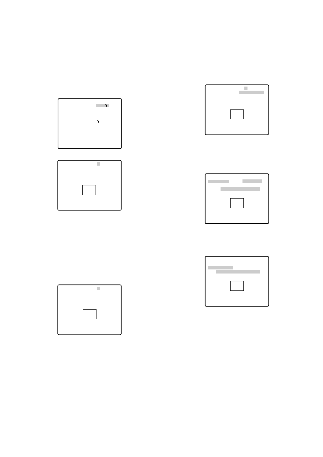
● Password Lock (PASSWORD LOCK)
Caution: For security, do not operate your VCR for
recording while the password menus are displayed
on the monitor.
A 3-digit number is used for a password to limit
access to all settings.
1. Move the cursor to PASSWORD LOCK, then select
ON or OFF with the joystick.
Note: ON or OFF can be selected only after going
through the password verification.
OFF: You can change all settings.
ON: You cannot change settings at all nor operate
AUTO PAN, SEQ, SORT, and PATROL.
2. Press the CAM (SET) key.
Password Verification
3. The password verification menu appears.
3-1 Select a numeral for the first digit with the joy-
stick, and press the CAM (SET) key. Though the
entered password is not displayed, the up-arrow
moves one character to the right.
3-2 Repeat the above step for the 2nd and 3rd dig-
its.
Default: 123
3-3 The cursor moves to OK after all the three digits
have been entered. Unless you want to change
the password, press the CAM (SET) key.
If the correct password is entered, the screen
returns to SET UP MENU. ON and OFF settings
are the same as made on the SET UP MENU
menu is as set in step 1.
If a wrong password is entered, the screen
returns to the verification menu. Repeat steps 3-1
to 3-3 to verify the password.
3-4 To cancel an incomplete password, move the
cursor to RESET, and press the CAM (SET) key.
The screen returns to the verification menu.
3-5 To return to the SET UP MENU menu without ver-
ifying the password, move the cursor to RET, and
press the CAM (SET) key.
New Password
4. To change the password in step 3-3 above, move
the cursor from OK to NEW PASSWORD, then press
the CAM (SET) key. NEW PASSWORD menu
appears.
Note: The NEW PASSWORD menu is accessible
only after the verification has been completed.
The up-arrow mark appears indicating the first digit
on the first line.
4-1 Enter a new three-digit password in the same
way as in steps 3-1 to 3-2.
4-2 The cursor moves to OK after all the three digits
have been entered. Press the CAM (SET) key to
move the cursor to the first digit on the second
line.
4-3 Enter the same password as the one you have
entered on the first line.
4-4 The cursor moves to OK. Press the CAM (SET)
key. If the new password is successfully entered,
the screen returns to SET UP MENU.
4-5 Retry steps 4-1 to 4-4. If the first entry for the
password is different from the second one, the
screen returns to the NEW PASSWORD? menu.
4-6 To return to the SET UP MENU menu without
changing the password, move the cursor to RET,
and press the CAM (SET) key.
** SET UP MENU **
PRESET 1
MAP
HOME POSITION
SELF RETURN
AUTO MODE
AUTO PAN KEY
DIGITAL FLIP
SPECIAL1
CAMERA
RS485 SET UP
PASSWORD LOCK OFF
** PASSWORD? **
0 1 2 3 4 5 6 7 8 9
. . .
OK RESET
NEW PASSWORD
RET
↑
OFF
OFF
OFF
AUTO PAN
ON
** NEW PASSWORD? **
0 1 2 3 4 5 6 7 8 9
. . .
. . .
OK RESET
RET
↑
-27-
■ Special 1 Menu Setting (SPECIAL 1)
● Privacy Zone (PRIVACY ZONE)
Up to 8 unwanted zones can be masked on the monitor
screen.
1. Move the cursor to PRIVACY ZONE and select ON
or OFF with the joystick. Press the CAM (SET) key to
display the ZONE NUMBER setting menu.
ON: Preset privacy zones are veiled on the monitor
screen.
OFF: The veiling function does not work.
2. Select a zone number with the joystick, and press
the CAM (SET) key.
•A zone number followed by * (asterisk) indicates
that the zone has already been registered.
• When a zone number having no * is selected, the
picture is zoomed out fully.
• When a registered zone number is selected, the
camera moves to the preset position. Note that if
you move PAN/TILT, ZOOM/FOCUS or ZONE
SCALE in that position, the registered zone number
having "*" is cancelled.
• The zone frame appears in the center of the screen
if 3 or fewer mask areas exist in that picture and if
the zone number is not registered yet.
• The privacy zone may appear on the monitor screen
depending on the direction of the camera.
• The privacy zone function will not work at start-up
immediately after turning the power on.
3. To register a new zone
3-1 For PAN/TILT, move the cursor to PUSH SET and
press the CAM (SET) key.
3-2 Adjust the pan and tilt position so that the
desired position comes into the zone frame with
the joystick.
3-3 For ZOOM/FOCUS, move the cursor to PUSH
SET , and press the CAM (SET) key.
3-4 Adjust zoom and focus, and press the CAM
(SET) key.
Zoom can be adjusted within the range of 1 to 10
magnifications.
3-5 Move the cursor to ZONE SCALE, and move the
joystick to the right or left to adjust the zone
frame. Press the CAM (SET) key after the adjustment.
** SPECIAL 1 **
PRIVACY ZONE OFF
PROPO.P/T ON
AREA TITLE OFF
PATROL STOP
ALARM IN/OUT
CLEANING OFF
EL-ZOOM ON
PRESET ALM OFF
IMAGE HOLD OFF
TILT ANGLE 0°
RET
** ZONE NUMBER 1/8 **
RET
** ZONE NUMBER 1/8 **
PAN/TILT →PUSH SET
ZOOM/FOCUS →PUSH SET
ZONE SCALE ••••|••••
SET DEL L H
RET
** ZONE NUMBER 3/8 **
PAN/TILT
ZOOM/FOCUS
ZONE SCALE ••••|••••
SET DEL L H
RET
→
PUSH SET
→
PUSH SET
** ZONE NUMBER 3/8 **
PAN/TILT →PUSH SET
ZOOM/FOCUS →PUSH SET
U TILT D/L PAN R
ZONE SCALE ••••|••••
SET DEL L H
RET
** ZONE NUMBER 3/8 **
PAN/TILT →PUSH SET
ZOOM/FOCUS →PUSH SET
U ZOOM D/L FOCUS R
ZONE SCALE ••••|••••
SET DEL L H
RET
-28-
Moving the joystick in the L direction decreases
the zone frame, and moving it in the H direction
increases it. However, the aspect ratio is fixed at
3 to 4.
The privacy zone setting has been completed.
The menu returns to the ZONE NUMBER setting
menu. If DEL is selected, zone setting is
released and the ZONE NUMBER setting menu
appears.
3-6
• To complete new settings and repeat other settings, move the cursor to SET and press the
CAM (SET) key. The ZONE NUMBER setting
menu reappears.
• To cancel new settings and return to the SPECIAL 1 menu, move the cursor to DEL and press
the CAM (SET) key. New settings are not registered.
• To complete new settings and return to the SPECIAL 1 menu, move the cursor to RET and press
the CAM (SET) key.
● Proportional Pan/Tilt (PROPO. P/T)
• Move the cursor to PROPO. P/T and select either
ON or OFF with the joystick.
Factory default setting: ON
ON: Pan/tilt speed is in inverse proportion to the
zoom ratio as follows:
Zoom ratio Speed level
x1 7 (fastest)
x2 5
x4 3
x8 1
x15 or more 0 (slowest)
* The speed level values are approximate.
OFF: The speed is constant at the fastest level
regardless of the zoom ratio.
● Area Title (AREA TITLE)
Up to 8 area titles can be added in specific positions.
1. Select ON (NESW), ON (USER) or OFF with the joystick.
ON (NESW): An area title is displayed for indicating
the camera direction: North (N), North-East (NE),
East (E), South-East (SE), South (S), South-West
(SW), West (W) and North-West (NW).
ON (USER): A user customized area title appears in
a maximum of 16 characters.
OFF: Area tittle does not appear.
Factory default setting: OFF
2. Press the CAM (SET) key. A submenu appears
except when OFF is selected.
Settings for ON (NESW)
1. Move the cursor to PUSH SET for PAN/TILT, and
press the CAM (SET) key. PAN/TILT is highlighted
and "U TILT D/L PAN R" appears.
2. Turn the camera north with the joystick, and press
the CAM (SET) key. The origin of the direction
(North) is set.
Note: Area titles are highlighted until the origin is
set.
** ZONE NUMBER 3/8 **
PAN/TILT →PUSH SET
ZOOM/FOCUS →PUSH SET
ZONE SCALE ••••|••••
SET DEL L H
RET
** SPECIAL 1 **
PRIVACY ZONE OFF
PROPO.P/T ON
AREA TITLE OFF
PATROL STOP
ALARM IN/OUT
CLEANING OFF
EL-ZOOM ON
PRESET ALM OFF
IMAGE HOLD OFF
TILT ANGLE 0°
RET
** SPECIAL 1 **
PRIVACY ZONE OFF
PROPO.P/T ON
AREA TITLE ON(USER)
PATROL STOP
ALARM IN/OUT
CLEANING OFF
EL-ZOOM ON
PRESET ALM OFF
IMAGE HOLD OFF
TILT ANGLE 0°
RET
** DIRECTION(NESW) **
PAN/TILT
ZOOM/FOCUS
POSI
+
N
RET
** DIRECTION(NESW) **
PAN/TILT
ZOOM/FOCUS
POSI
U TILT D/L PAN R
+
N
RET
→
PUSH SET
→
PUSH SET
→
PUSH SET
→
PUSH SET
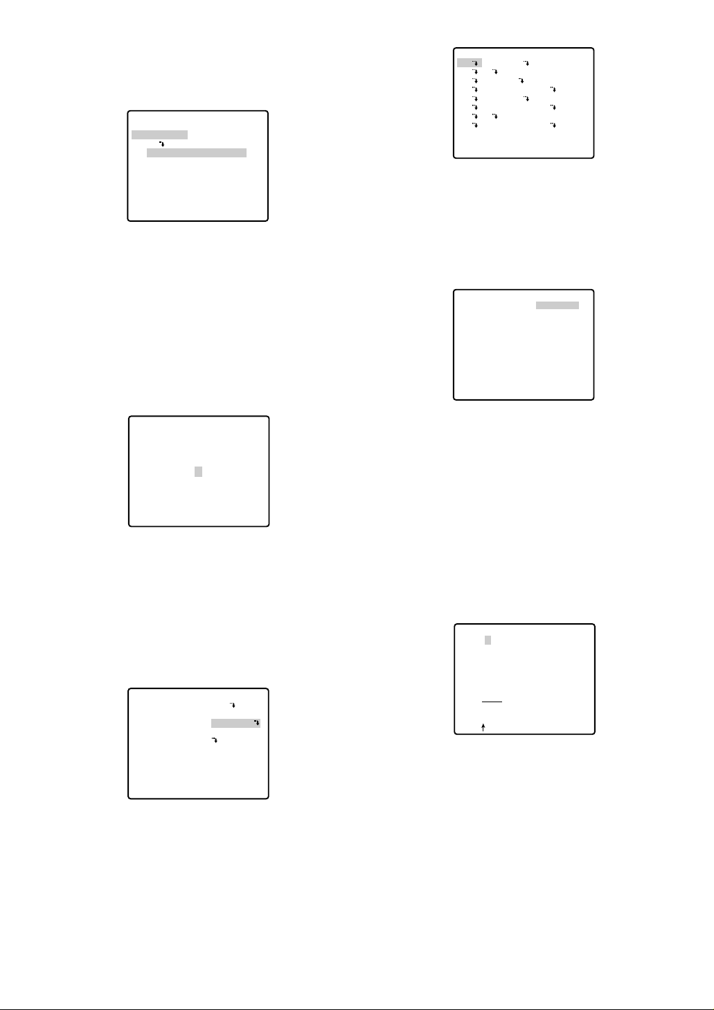
-29-
3. Move the cursor to PUSH SET for ZOOM/FOCUS,
and press the CAM (SET) key. ZOOM/FOCUS is
highlighted and "U ZOOM D/L FOCUS R" appears.
4. Adjust the zoom or focus with the joystick.
5. Move the cursor to POSI
O, and press the CAM
(SET) key. The area title position appears on the
monitor screen. If needed, change the display position with the joystick, and press the MON (ESC) key.
An area title always appears under the camera ID.
If the camera ID and an area title are set to be
shown in separate positions, the area title appears
above the camera ID.
6. Move the cursor to RET, and press the CAM (SET)
key. The SPECIAL 1 menu appears again.
Setting for ON (USER)
If ON (USER) is selected on the SPECIAL 1 menu,
the AREA TITLE (USER) menu appears. The screen
has a number column and title column above RET
and RESET.
Note: An area number followed by an asterisk * has
already been preset.
1. To select a camera direction, move the cursor to the
desired number, and press the CAM (SET) key. The
direction menu of the selected number appears.
2. Adjust PAN/TILT, ZOOM/FOCUS and display the
position in the same way as AREA TITLE, DIRECTION (NESW). See page 28.
3. To add a user-customized title, move the cursor to
the title of the desired number, and press the CAM
(SET) key. The AREA TITLE menu of the selected
number appears.
Area Title Editing
1. Move the cursor to the desired character in the
character field with the joystick, and press the CAM
(SET) key.
2. The selected character appears in the editing field
and the blinking cursor moves one position to the
right.
3. Repeat steps 1 and 2 until one area title is completed.
4. Move the cursor to POSI
O, and press the CAM
(SET) key. The area title appears on the monitor
screen. If needed, change the display position with
the joystick, and press the MON (ESC) key.
** DIRECTION(NESW) **
PAN/TILT
ZOOM/FOCUS
POSI
U ZOOM D/L FOCUS R
+
N
RET
→
PUSH SET
→
PUSH SET
N
** AREA TITLE(USER) **
1* NORTH
2
3 EAST
4 SOUTH-EAST
5 SOUTH
6 SOUTH-WEST
7
8 NORTH-WEST
RET RESET
** DIRECTION(USER) 1 **
PAN/TILT
ZOOM/FOCUS
+
NORTH
RET DEL
→
PUSH SET
→
PUSH SET
** SPECIAL 1 **
PRIVACY ZONE OFF
PROPO.P/T ON
AREA TITLE ON(USER)
PATROL STOP
ALARM IN/OUT
CLEANING OFF
EL-ZOOM ON
PRESET ALM OFF
IMAGE HOLD OFF
TILT ANGLE 0°
RET
AREA TITLE 1
0123456789
ABCDEFGHIJKLM
NOPQRSTUVWXYZ
().,'":;&#!?=
+-*/%$
SPACE
POSI RET RESET
................
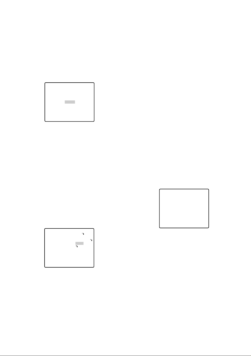
-30-
To Quit Editing
• To return to the AREA TITLE menu, move the cursor
to RET, and press the CAM (SET) key.
• To cancel one area title, move the cursor to RESET
in the AREA TITLE menu, and press the CAM (SET)
key.
• To return to the SPECIAL 1 menu, move the cursor
to RET, and press the CAM (SET) key.
• To erase all the area titles, move the cursor to
RESET in the AREA TITLE (USER) selection menu,
and press the CAM (SET) key.
Notes:
• An area title appears under the camera ID if both
are set in the same position. If the setting is different, they appear in the area title position.
• In case of sharing a common subject in a scene
of other camera number, the nearest area title
appears while the camera direction deviates
within 45 ° from the set position. If two or more
area numbers are set in the same position, the
title of the highest number appears.
● Patrol-learn and Patrol Play (PATROL)
A routine of manual operations can be stored for 1
minute at the maximum and reproduced repetitively.
PATROL
1. Set the following parameters for the patrol-learn
starting position. These parameters are stored when
the patrol-learn mode starts.
• PAN/TILT/ZOOM/FOCUS
• IRIS
• SHUTTER
• AGC
• SENS UP
• WHITE BALANCE
•IMAGE HOLD
• AREA TITLE
• DIGITAL FLIP
• PRIVACY ZONE
• CAMERA ID
•PROPO.PT
• PAN LIMIT
• ZOOM LIMIT
• TILT ANGLE
• BURST
• CLEANING
After starting the patrol-learn, the following manual
operations are stored.
• PAN/TILT/ZOOM/FOCUS operation
• IRIS operation
• Preset positioning
2. Open the SET UP menu and move the cursor to
SPECIAL 1. For PATROL, select LEARN, PLAY or
STOP with the joystick.
The factory default setting is STOP.
LEARN: A series of manual operations is stored.
PLAY: Stored operations are reproduced.
STOP: LEARN or PLAY is not activated.
PATROL LEARN with a Controller Having PATROL
Key
1. Press the PATROL key and the CAM (SET) key
simultaneously to start patrol-learn. The setup menu
displays "LEARNING(60S)", and the starting points
are stored.
2. Operate patrol-learn manually. The operation data is
stored. The countdown to complete learning is displayed.
3. To stop patrol-learn, press the PATROL STOP key.
Patrol-learn with a Controller not Having the
PATROL Key
1. Close the SET UP or SPECIAL 1 menu to start
PATROL LEARN. Starting point parameters are
stored and "LEARNING(60S)" is displayed on the
monitor.
2. Operate patrol-learn manually.
NORTH
** SPECIAL 1 **
PRIVACY ZONE OFF
PROPO.P/T ON
AREA TITLE ON(USER)
PATROL PLAY
ALARM IN/OUT
CLEANING OFF
EL-ZOOM ON
PRESET ALM OFF
IMAGE HOLD OFF
TILT ANGLE 0°
RET
LEARNING(60S)
 Loading...