

Page 1
Combination Camera
WV-CS400
Before attempting to connect or operate this product, please read these instructions completely
Page 2
The lightning flash with arrowhead
symbol, within an equilateral triangle, is
interned to alert the user to the
presence of uninsulated "dangerous
voltage" within the product's enclosure
that may be of sufficient magnitude to
constitute a risk of electric shock to
persons.
The exclamation point within an
equilateral triangle is intended to alert
the user to the presence of important
operating and maintenance (servicing)
instructions in the literature
accompanying the appliance.
The serial number of this product may be found on the
bottom of the unit.
You should note the serial number of this unit in the
space provided and retain this book as a permanent
record of your purchase to aid identification in the event
of theft.
Model No.
Serial No.
CAUTION:
TO REDUCE THE RISK OF ELECTRIC SHOCK,
DO NOT REMOVE COVER (OR BACK), NO
USER SERVICEABLE PARTS INSIDE.
REFER SERVICING TO QUALIFIED SERVICE
PERSONNEL.
CAUTION
RISK OF ELECTRIC SHOCK
DO NOT OPEN
ENGLISH VERSION
THIS APPARATUS MUST BE EARTHED.
To ensure safe operation the three-pin plug supplied must be
inserted only into a standard three-pin power point which is
effectively earthed through the normal household wiring.
Extension cords used with the equipment must be three-core and
be correctly wired to provide connection to earth. Wrongly wired
extension cords are a major cause of fatalities.
The fact that the equipment operates satisfactorily does not imply
that the power point is earthed and that the installation is
completely safe. For your safety, if in any doubt about the
effective earthing of the power point, consult a qualified
electrician.
For Australia
For U.K.
FOR YOUR SAFETY PLEASE READ THE FOLLOWING TEXT
CAREFULLY.
This appliance is supplied with a moulded three pin mains plug for your
safety and convenience.
A 13 amp fuse is fitted in this plug.
Should the fuse need to be replaced please ensure that the replacement
fuse has a rating of 13 amp and that it is approved by ASTA or BSI to
BS1362.
Check for the ASTA mark
H or the BSI mark G on the body of the
fuse.
If the plug contains a removable fuse cover you must ensure that it is
refitted when the fuse is replaced.
If you lose the fuse cover the plug must not be used until a replacement
cover is obtained.
A replacement fuse cover can be purchased from your local Panasonic
Dealer.
IF THE FITTED MOULDED PLUG IS UNSUITABLE FOR THE
SOCKET OUTLET IN YOUR HOME THEN THE FUSE SHOULD BE
REMOVED AND THE PLUG CUT OFF AND DISPOSED OF SAFELY.
THERE IS A DANGER OF SEVERE ELECTRICAL SHOCK IF THE
CUT OFF PLUG IS INSERTED INTO ANY 13 AMP SOCKET.
If a new plug is to be fitted please observe the wiring code as shown
below.
If in any doubt please consult a qualified electrician.
WARNING: This apparatus must be earthed.
IMPORTANT
The wires in this mains lead are coloured in accordance with the
following code.
Green-and-yellow: Earth
Blue: Neutral
Brown: Live
As the colours of the wire in the mains lead of this appliance may
not correspond with the coloured markings identifying the terminals in
your plug, proceed as follows.
The wire which is coloured green-and-yellow must be connected to
the terminal in the plug which is marked with the letter E or by the earth
symbol I or coloured green or green-and-yellow.
The wire which is coloured blue must be connected to the terminal
in the plug which is marked with the letter N or coloured black.
The wire which is coloured brown must be connected to the
terminal in the plug which is marked
with the letter L or coloured red.
How to replace the fuse
Open the fuse compartment with
a screwdriver and replace the fuse
and fuse cover.
WARNING: TO PREVENT FIRE OR ELECTRIC SHOCK HAZARD, DO NOT EXPOSE THIS APPLIANCE TO
RAIN OR MOISTURE.
Wij verklaren als enige aansprakelijke, dat het product
waarop deze verklaring betrekking heeft, voldoet aan de
volgende normen of andere normatiefve dokumenten,
overeenkomstig de bepalingen van Richtlijnen 73/23/EEC en
89/336/EEC.
Vi erklærer os eneansvarlige for, at dette produkt, som denne
deklaration omhandler, er i overensstemmelse med den
følgende standarder eller andre normative dokumenter i følge
bestemmelserne i direktivene 73/23/EEC og 89/336/EEC.
Vi deklarerar härmed värt fulla ansvar för att den produkt till
vilken denna deklaration hänvisar är i överensstämmelse
med standarddokument, eller andra normativa dokument som
framstölls i Direktiv 73/23/EEC och 89/336/EEC.
Ilmoitamme yksinomaisella vastuullamme, että tuote, jota
tämä ilmoitus koskee, noudattaa seuraavia standardeja tai
muita ohjeellisia asiakirjoja, jotka noudattavat direktiivien
73/23/EEC ia 89/336/EEC. säädöksiä.
Vi erklærer oss alene ansvarlige for at produktet som denne
erklæringen gjelder for, er i overensstemmelse med følgende
normer eller andre normgivende dokumenter som fælger
bestemmelsene i direktiven 73/23/EEC og 89/336/EEC.
We declare under our sole responsibility that the product
to which this declaration relates is in conformity with the
standards or other normative documents following the
provisions of Directives EEC/73/23 and EEC/89/336.
Noi dichiariamo sotto nostra esclusiva responsabilità che il
prodotto a cui si riferisce la presente dichiarazione risulta
conforme ai seguenti standard o altri documenti normativi
conformi alle disposizioni delle direttive CEE/73/23 e
CEE/89/336.
Page 3

Page 4

CONTENTS
PREFACE .......................................................... 2
FEATURES ........................................................ 2
PRECAUTIONS ................................................. 2
MAJOR OPERATING CONTROLS AND
THEIR FUNCTIONS ........................................... 3
SETUP PROCEDURE ........................................ 4
■ Setup Menu ............................................... 4
■ Setup Menu Description ............................ 7
■ Setting Procedures ................................... 10
INSTALLATION ................................................. 20
CONNECTIONS ................................................ 22
SYSTEM CONNECTION .................................... 23
PREVENTION OF BLOOMING
AND SMEAR ...................................................... 24
SPECIFICATIONS ............................................... 25
ACCESSORIES ................................................... 25
OPTIONAL ACCESSORIES ................................ 25
- 1 -
ENGLISH
The model numbers listed in this Operating Instructions have no suffixed attached to it.
Page 5

- 2 -
PREFACE
Panasonic presents highly advanced CCVE technology to meet the demand of new and ever-changing
applications. The WV-CS400 is unitized colour video
surveillance device which features 1/3" CCD Digital
Signal Processing (DSP) high performance camera,
pan/tilt mechanism, 10 times zoom lens and
receiver in its compact enclosure.
The camera portion incorporates 1/3" high sensitive
CCD and provides 480-line horizontal resolution
and 48 dB of S/N ratio. Also WV-CS400 feature
advanced digital signal processing circuit which
enables a surveillance of the next age.
Pan & tilt portion is especially designed to meet
your specific needs.
WV-CS400 features 360 degree endless panning. A
unitized surveillance devices, Panasonic WV-CS400
give you the edge of high technology of advanced
video surveillance.
FEATURES
1. Maximum 24 degree/sec. speed for automatic
and manual panning.
2. 360 degree endless panning.
3. The following functions are built in.
(1) Auto Light Control (ALC)/Manual Override
Iris
(2) Character Generator
(3) Back Light Compensation (Auto: Factory
preset, Manual: Manual photometric
measuring area set)
(4) Auto/Manual White Balance Function
(5) Electronic Shutter Function
4. Signal-to-noise ratio of 48 dB
5. Minimum illumination of 3 lx
6. 480 lines of horizontal resolution
7. High quality picture:
(a) 2H type vertical enhancer for greater
picture sharpness
(b) Chroma averaging circuit for better colour
signal to noise ratio
(c) Minimum of aliasing on fine objects
(d) Expanded dynamic range by use of knee
circuit
(e) Highlight aperture correction for greater
picture detail of bright object
8. Back Light Compensation for use against
unusual lighting conditions.
PRECAUTIONS
• Do not attempt to disassemble this unit. There
are no user serviceable parts inside. Refer
servicing to qualified service personnel.
• This unit is designed for indoor use. So mount
this any other place which allows to avoid the
rain or moisture.
• Be sure to mount on flat ceiling.
• Do not drop the metalic parts through slots.
This action could permanently damage this
unit. Do turn the power off immediately and
refer servicing to qualified service personnel.
• Wipe the enclose regularly by using a soft and
dry cloth, or a cloth moistened with a solution of
water and normal kitchen detergent.
Do not use chemicals for cleaning the
enclosure as it may damage the surface.
• Every necessary procedures with regard to
install this product should be made by qualified
service personnel or system installers.
• Use this unit in an environment where the
temperatures is within
−10°C - +50°C (14°F -
122°F), and the relative humidity within 90%.
• Never aim the camera at bright objects.
Whether the camera is in use or not, never aim
it at the sun, or other extremely bright objects
as this could cause blooming.
• Do not mount this unit except the ceiling mount.
The standing mount makes the picture upside
down, and the movement of the panning and
tilting to reverse.
Page 6
- 3 -
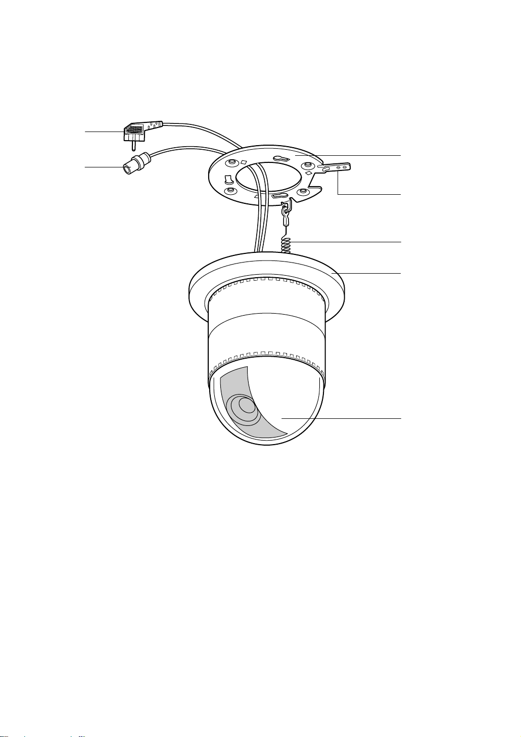
MAJOR OPERATING CONTROLS AND THEIR FUNCTIONS
q
w
e
r
t
y
u
(1) Video Output Connector
(2) Power Cable
(3) Camera Mounting Angle
(4) Pan/Tilt Starting Point
(5) Fall Prevention Wire
(6) Decoration Cover
(7) Dome Cover
Page 7
- 4 -
Auto-Pan
On/Off
White
Balance
AWC
ATW
Manual
Level
Adjustment
Manual
Level
Adjustment
Manual
Mask
Area
Selection
Manual
Mask
Area
Selection
Special
Menu
Camera
Reset
PedestalGainChroma
Gain
Page 8
- 5 -
Camera ID
Display
Position
Camera
ID
Editing
Light
Control
ALC
MANUAL
Shutter
Speed
ON/OFF
Manual
Iris
Adjustment
AGC
ON/OFF
Sync.
INT/LL
INT
Manual
Selection
LL
Manual
Selection
VD2
Automatic
Selection
V-phase
Manual
Adjustment
Setup
Menu
Preset
Off
Preset ON
(Back Light
Compensation)
Manual
Level
Adjustment
(Contrast)
Manual
Mask Area
Selection
The above menus should be set with the following
switches.
• In Case of WV-CU550A
Joystick: Used to move the Cursor
Upward/Downward/Right/Le
ft and select the mode.
Also used to adjust the
level.
CAM (SET) Button: The mode is set by this
switch. Also, the menus can
be changed by this switch.
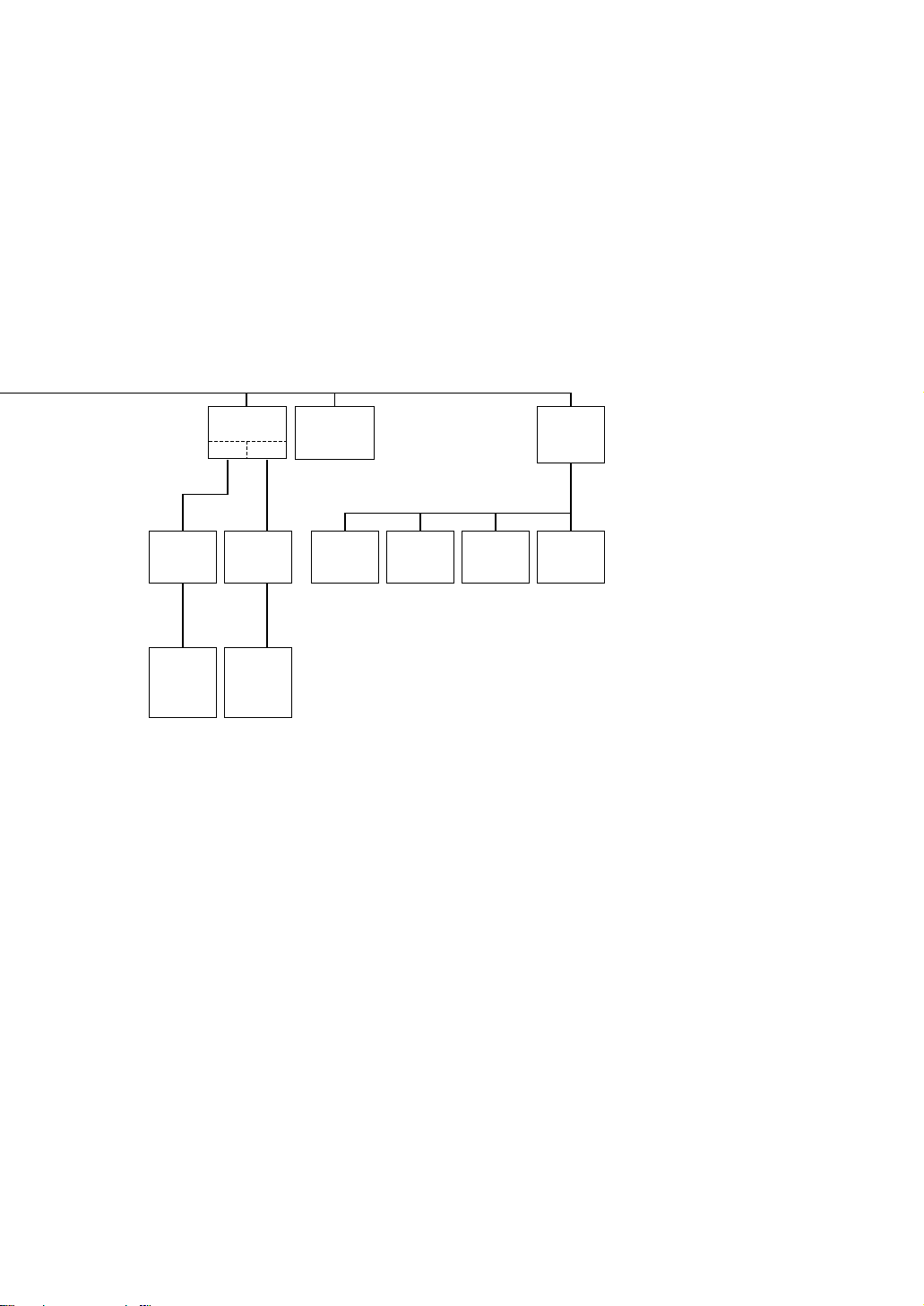
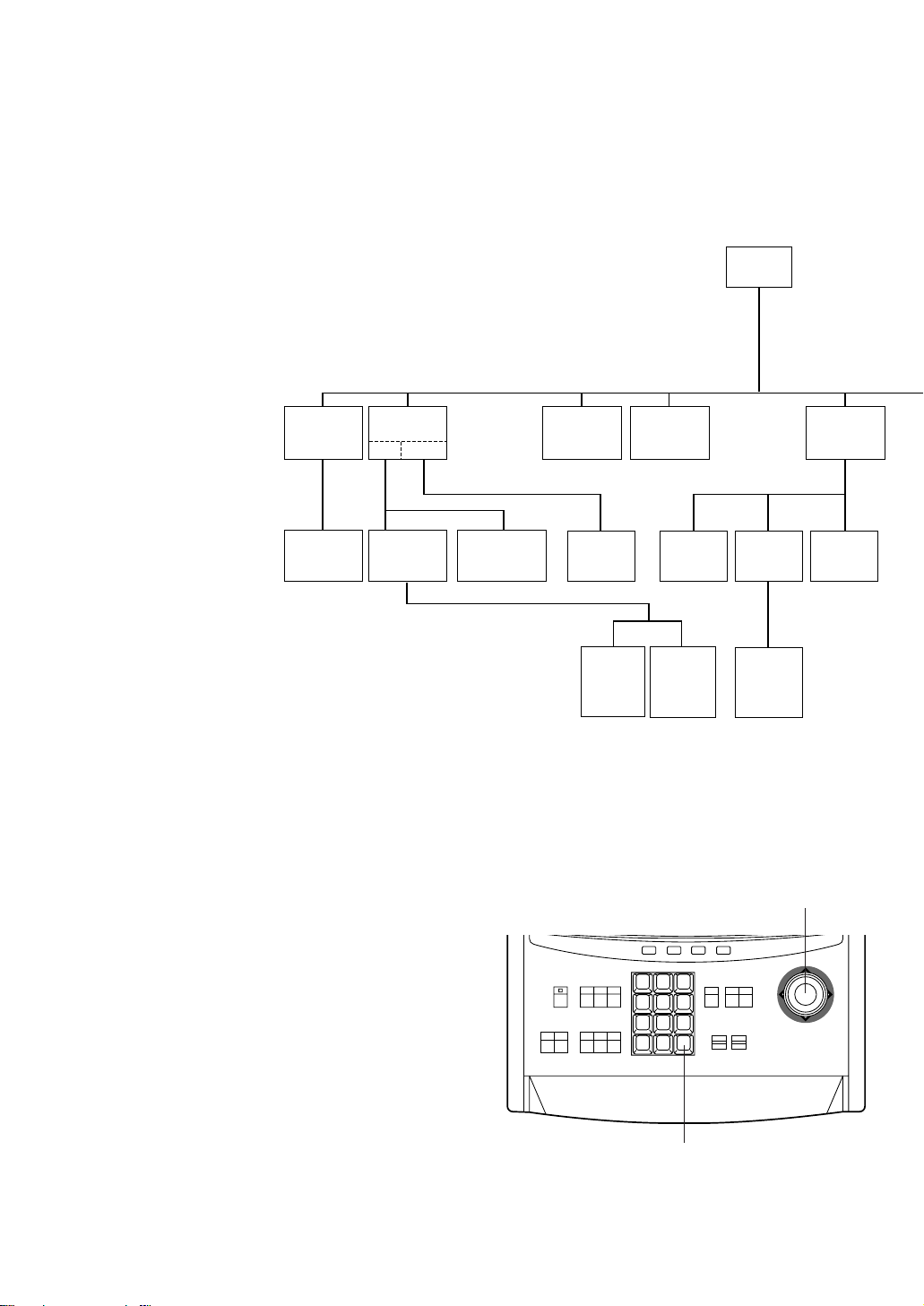
SETUP PROCEDURE
■ Setup Menu
This camera utilizes a user setup menu that is
displayed on-screen.
This setup menu contains various sub menus with a
Tree-Type structure as shown below.
This menu is described in the "SETUP MENU
DESCRIPTION".
1 2 3
4 5 6
7 8 9
MON CAM
ESC SET
0
ACK
RESET
BACK
SEQ
FORWARD
SEQ ALT
DEC
-1CAM
INC
+1CAM
STOP12
AUX
CLOSE
OPEN
IRIS
PRESET
FOCUS
NEAR
ZOOM
TELE
FAR
WIDE
System Controller WV-CU 550A
LEFT
RIGHT
UP
DOWN
F3 F4F2F1
AF
Joystick
CAM (SET) Button
Page 9

- 6 -
Left Switch
Set Switch
Right Switch
Down Switch
Up Switch
• In Case of WV-RM70
Up Switch: Moves the cursor upwards.
Down Switch: Moves the cursor downwards.
Right Switch: Moves the cursor right. The
mode is also selected by this
switch and adjustment of certain
levels can be made by this
switch.
Left Switch: Moves the cursor left. The mode
is also selected by this switch
and adjustment of certain levels
can be made by this switch.
Set Switch: The mode is set by this switch.
Also, the menus can be changed
by this switch.
Page 10

- 7 -
■ Setup Menu Description
● Camera
(1) Camera Identification (CAMERA ID)
Up to 16 alpha/numeric characters for camera identification can be
displayed near the bottom of the picture.
The ID display ON or OFF mode is selected by the primary setup
menu and the editing of displayed characters is performed in the
associated sub menu.
Note:
Refer to the Camera Identification Setting for more details.
(2) Light Control (ALC/MANUAL)
The lens iris can be controlled automatically or manually.
• Back Light Compensation (BACK LIGHT COMP)
With conventional cameras, strong background lighting, such as a
spotlight, interferes with the clarity of important scene objects,
making them appear dark. This camera is equipped with a back light
compensation function to overcome this problem.
Setup Menu Tree, both the ALC light control modes can select either
Preset ON or Preset OFF for Back Light Compensation.
<WV-CS400 Preset ON>
B
<Conventional Camera>
Night Day
** SET UP **
CAMERA ID OFF *
ALC/MANUAL ALC *
SHUTTER OFF
AGC ON
SYNC INT
WHITE BAL ATW *
AUTO PAN OFF
SPECIAL *
** SET UP **
CAMERA ID OFF *
ALC/MANUAL ALC *
SHUTTER OFF
AGC ON
SYNC INT
WHITE BAL ATW *
AUTO PAN OFF
SPECIAL *
Night Day
• Factory Setup Mode (PRESET ON)
In normal use the important object in a
scene is placed in the centre of the
monitor's screen. In the factory setup
mode, more photometric weight is given to
the centre of the screen (where the
important object is located) than is given to
the edge of the picture (where a bright
back light would most likely be located). In
this mode, even though the backlight may
vary, the object at the centre of the screen
can still be clearly seen.
Note:
Refer to the Light Control Setting on page
12 for detailed procedures.
B
Camera ID
WV-CS400
Page 11

- 8 -
• Field Setup Mode (PRESET OFF)
This mode is effective in conditions where the
important object in the scene is not located
centrally in the picture and when a bright light
source is located near the centre of the
screen.
A conventional camera cannot cope with these
situations.
However, by using the WV-CS400 in the preset
"OFF" mode, it is possible to compensate for
difficult lighting conditions. In this mode, the
picture is divided into 48 zones or mask areas.
It is possible to mask (or tell the camera to
ignore) any bright light sources in those mask
areas that might interfere with picture clarity.
For example, a strong spotlight in the background might cause the lens iris to close down
Night Day
B
<Conventional Camera>
<WV-CS400 Masked>
Night and Day
so much that all other objects in the scene
appear dark. With the field setup mode for
back light compensation, it is possible to mask
out the spotlight and increase the rest of the
scene's brightness as shown below.
In addition to the mask area setup, the overall
video output level can be adjusted by using the
level adjustment (LEVEL) while in the preset
"OFF" mode for both the ALC and ELC modes.
Note:
The end result of the field setup of the
mask area and level adjustment is the
generation of a feed back control signal to
the lens iris when in the ALC mode or a
exposure time control signal to the CCD
image sensor when in the ELC mode.
(3) Shutter Speed (SHUTTER)
The electronic shutter speed can be select from 1/50 second (OFF) to
1/120 - 1/10000 second.
Note:
Refer to the Shutter Speed Setting on page 14 for detailed procedures.
OFF 1/120 1/250 1/500
1/1000 1/2000 1/4000 1/10000
(4) Gain Control (AGC)
The gain control mode can be selected between automatic gain control
(AGC ON) and manual gain control (AGC OFF) by this menu.
Note:
Refer to the Gain Control Setting on page 14 for detailed procedures.
** SET UP **
CAMERA ID OFF *
ALC/MANUAL ALC *
SHUTTER OFF
AGC ON
SYNC INT
WHITE BAL ATW *
AUTO PAN OFF
SPECIAL *
** SET UP **
CAMERA ID OFF *
ALC/MANUAL ALC *
SHUTTER OFF
AGC ON
SYNC INT
WHITE BAL ATW *
AUTO PAN OFF
SPECIAL *
(5) Synchronization (SYNC)
In the Setup Menu it is possible to select either the internal sync
mode (INT) or the line-lock sync mode (LL).
Additionally, this camera accepts the VD2 signal, which is the vertical
drive signal multiplexed with the composite video output signal from
a component such as the WJ-MP404 Multiplex Unit. The VD2 signal
allows for roll-free vertical interval switching in a sequential
switcher.Whenever VD2 is supplied to this camera, the camera
automatically switches into the VD2 sync mode.
In the submenus of the synchronization section of the Setup Menu,
adjustments are possible for the vertical phase adjustment for the
line-lick mode, horizontal phase adjustment for the composite sync
mode, and horizontal and sub-carrier phase adjustments for the
black burst mode.
** SET UP **
CAMERA ID OFF *
ALC/MANUAL ALC *
SHUTTER OFF
AGC ON
SYNC INT
WHITE BAL ATW *
AUTO PAN OFF
SPECIAL *
Page 12

- 9 -
(6) Synchronization (SYNC)
Important Notice:
The priority of sync mode is as follows.
1. Multiplexed Vertical Drive (VD2) (Highest)
2. Line-lock (LL)
3. Internal Sync (INT) (Lowest)
Note:
The automatic sync mode selection is made according to priority listed above. Refer to the
Synchronization Setting on page 14 for detailed procedures.
(7) White Balance (WHITE BAL)
A colour characteristic of illumination is called
colour temperature and it is measured in units
of Kelvin (°K).
The higher colour temperatures are
considered bluish while the lower colour
temperatures are more reddish.
A camera shooting a scene with high colour
temperature illumination produces a bluish
picture. Likewise, it will produce a reddish
picture with lower colour temperature illumination. Therefore, in order for the camera to
reproduce a scene accurately, it needs to be
white balanced before shooting.
Blue sky
Cloudy
Fine
AWC
10000°K
9000°K
8000°K
7000°K
6000°K
5000°K
4000°K
3000°K
2000°K
1000°K
ATW
Halogen lamp
Rainy
Partly cloudy
Fluorescent
lamp
Tangsten
lamp
Candle
Selection of the white balance control mode,
either auto-tracing white balance (ATW) or
one-touch automatic white balance (AWC),
can be made through the use of this menu.
• Auto-Tracing White Balance Mode (ATW)
In the ATW mode the colour temperature of the illuminant is
continuously monitored and the white balance of the camera is
automatically set.
The ATW mode has a range of operation from approximately 2600°K
- 6000°K. Beyond this range, use the Automatic White Balance
(AWC) mode.
The ATW mode might not produce optimum colour rendition under
the following conditions.
1. When the scene consists mostly of strongly coloured objects or
illumination such as a blue sky or during sunset.
2. When the scene is dimly lit.
In these cases, use the AWC mode.
• Automatic White Balance Control Mode (AWC)
In this mode, accurate white balance may be obtained within a range
of operation from approximately 2300°K- 10000°K.
Note:
Refer to the White Balance Setting on page 16 for detailed
procedures.
** SET UP **
CAMERA ID OFF *
ALC/MANUAL ALC *
SHUTTER OFF
AGC ON
SYNC INT
WHITE BAL ATW *
AUTO PAN OFF
SPECIAL *
Page 13

- 10 -
(8) Special Menu (SPECIAL)
Chroma level, aperture level, and pedestal level can be adjusted.
Your settings can be released to return to the default settings.
See page 18 for the setting method.
* SPECIAL *
CHROMA GAIN ....I....
AP GAIN ....I....
PEDESTAL .I.......
− +
CAMERA RESET →PUSH SW
RET
(9) Automatic Panning (AUTO PAN)
Select one of the two panning modes below.
OFF : Operates the panning manually
AUTO PAN : Operates the panning automatically with the preset
panning range.
** SET UP **
CAMERA ID OFF *
ALC/MANUAL ALC *
SHUTTER OFF
AGC ON
SYNC INT
WHITE BAL ATW *
AUTO PAN OFF
SPECIAL *
■ MENU DISPLAY
● Setup Menu Display
1. Select the numbers of a camera to set up and a monitor to display the
setup menu.
2. Display the D4 menu using the cursor.
3. Press the F1 key.
The setup menu appears on the monitor.
4. To close the setup menu, press the F4 key.
● Submenu Display
The items having ∗mark enable the editing of the submenu.
1. Move the cursor to an item having ∗mark and press the CAM (SET)
button.
The submenu is displayed.
D4 menu
** SET UP **
CAMERA ID OFF *
ALC/MANUAL ALC *
SHUTTER OFF
AGC ON
SYNC INT
WHITE BAL ATW *
AUTO PAN OFF
SPECIAL *
Setup menu
■ Setting Procedures
The following setting procedures are described on the assumption that the WV-CU550A is used. Refer to the
Operating Instructions of WV-CU550A.
F1 F2 F3 F4
Camera Set up menu
Res A.Res EXIT
F2 F3 F4
Camera Set up menu
On EXIT
F1
Page 14

- 11 -
■ CAMERA SETTING
1. To display Camera Setting Menu
1. Move the cursor to CAMERA∗, and press the CAM (SET) button. The
camera setting menu is displayed.
** SET UP **
CAMERA ID OFF *
ALC/MANUAL ALC *
SHUTTER OFF
AGC ON
SYNC INT
WHITE BAL ATW *
AUTO PAN OFF
SPECIAL *
Setup menu
Camera ID setting menu
ABCDEFGHIJKLM
NOPQRSTUVWXYZ
0123456789
().,'":;&#!?=
+−*/%$ДЬЦЖСЕ
← →
SPACE
POSI RET RESET
WV-CS400.......
Setup menu
ABCDEFGHIJKLM
NOPQRSTUVWXYZ
0123456789
().,'":;&#!?=
+−*/%$ДЬЦЖСЕ
← →
SPACE
POSI RET RESET
WV-CS400.......
ABCDEFGHIJKLM
NOPQRSTUVWXYZ
0123456789
().,'":;&#!?=
+−*/%$ДЬЦЖСЕ
← →
SPACE
POSI RET RESET
WV-CS400.......
2. Camera Identification (CAMERA ID) Setting
• Move the cursor to the "CAMERA ID" mode position, and select either
"ON" (Camera identification characters are displayed) or "OFF" mode
by using the Joystick.
• When the camera identification character needs editing, perform the
following steps by using the submenu of Camera Identification.
• Move the cursor to the "CAMERA ID" mode position and press the
CAM (SET) Button to display the Character Editing menu.
• The character cursor on the letter "A" and the editing cursor on the left
end of the editing area starts blinking.
• Move the character cursor to the desired letter by using the Joystick
and then press the CAM (SET) Button. The selected letter is written to
the editing cursor position. (The blinking Editing Cursor moves to right
automatically at this moment.)
• Repeat the above procedure until all character editing is completed.
• When the position of the editing cursor is to be shifted in the editing
area, move the character cursor to the "←" or "→" and press the CAM
(SET) Button. This function is used to move the editing position or to
correct an individual character.
• When a blank space is needed, move the character cursor to the
"SPACE" position and press the CAM (SET) Button. The blank space
is inserted into the cursor position in the editing area.
• When all characters in the editing area are to be erased, move the
character cursor to the "RESET" position and press the CAM (SET)
Button.
• After completing the editing of the Camera Identification characters,
the display position of the Camera Identification characters on the
monitor screen can be set as follows.
• Move the character cursor to the "POSI" position and press the CAM
(SET) Button to display the ID position menu. The characters of the
camera ID start blinking to identify the selection of the positioning
menu.
ABCDEFGHIJKLM
NOPQRSTUVWXYZ
0123456789
().,'":;&#!?=
+−*/%$ДЬЦЖСЕ
← →
SPACE
POSI RET RESET
WV-CS400.......
Page 15

- 12 -
• The display position of the camera ID on the monitor screen can be
placed anywhere on the screen by using the Joystick.
Notes:
1. The positioning of the camera ID stops at the edges of the
monitor screen.
2. The camera ID moves faster when the Joystick is kept pressed
for more than 0.5 seconds.
• After completing the positioning of the camera ID, press the CAM
(SET) Button to return to the Character Editing menu.
• To return to the normal camera picture mode, move the character
cursor to the "END" position and press the CAM (SET) Button.
• To return to the Setup menu for setting other items, move the
character cursor to the "RET" position and press the CAM (SET)
Button.
ABCDEFGHIJKLM
NOPQRSTUVWXYZ
0123456789
().,'":;&#!?=
+-*/%$ДЬЦЖСЕ
← →
SPACE
POSI RET RESET
WV-CS400.......
3. Light Control Setting (ALC/ELC)
• Display the Setup menu.
• If necessary, refer to Setup Menu Display, for details on displaying the
Setup menu on the monitor screen.
• Move the cursor to the "ALC/MANUAL" mode position and select
either the "ALC" or "MANUAL" mode by using the Joystick.
Note:
The back light compensation setting sub menu associated with
this menu is described separately and should be setup after
installing the camera at the site and observing the actual site
picture.
** SET UP **
CAMERA ID OFF *
ALC/MANUAL ALC *
SHUTTER OFF
AGC ON
SYNC INT
WHITE BAL ATW *
AUTO PAN OFF
SPECIAL *
Setup menu
* ALC CONT *
BACK LIGHT COMP
PRESET OFF
MASK SET *
LEVEL ....I....
− +
RET
* ALC CONT *
BACK LIGHT COMP
PRESET OFF
MASK SET *
LEVEL ....I....
− +
RET
Backlight compensation menu
4. Back Light Compensation Setting (BACK LIGHT COMP)
(1) ALC Mode
• Confirm that the ALC mode is selected as follows.
• Display the Setup menu.
• If necessary, refer to Setup Menu Display, for details on displaying the
Setup menu on the monitor screen.
• Move the cursor to the "ALC/MANUAL" mode position and select the
"ALC" mode by using the Joystick.
Page 16

- 13 -
* ALC CONT *
BACK LIGHT COMP
PRESET OFF
MASK SET *
LEVEL ....I....
− +
RET
(1)-1 ALC Mode with Preset Mode (PRESET ON)
• Move the cursor to the "PRESET" mode position and select the "ON" mode by using the Joystick. The
preset mode menu is displayed on the monitor screen as shown.
• Move the cursor to "RET" position by using the Joystick and press the CAM (SET) Button to return to the Set
Up menu.
(1)-2 ALC Mode with Field Setup Mode (PRESET OFF)
• Move the cursor to the "PRESET" mode position and select the "OFF"
mode by using the Joystick.
• The field setup menu is displayed on the monitor screen as shown.
• Move the cursor to the "MASK SET" mode position and press the CAM
(SET) Button. The 48 Mask Areas appears on the monitor screen.
The left top area has a blinking cursor.
• To mask this area, press the CAM (SET) Button. The mask and the
cursor start blinking alternately.
B
Blinking
Blinking
Blinking
Turns to white
• To mask other areas, move the cursor to the desired area by using
the Joystick. Then press the CAM (SET) Button to mask that area.
The area turns to white.
• When the cursor is moved to an area that has already been masked,
the mask and cursor start blinking alternately.
• Press the CAM (SET) Button if this masking for this area is to be
canceled.
• Press the F2 Button of WV-CU550A when all masking areas are to be
canceled.
• After masking is completed, press the CAM (SET) Button for more
than 2 seconds. The 48 Mask Areas on the monitor screen disappear
and the field setup menu is then displayed.
• If the video output level (picture contrast) is to be changed, move the
cursor to the "LEVEL" mode position and control the Joystick to adjust
the iris of the ALC lens. When the cursor is moved in the right (+)
direction, the lens iris is opened wider, causing the video output level
to rise.
If the cursor is moved in the left (−) direction the reverse takes place.
• Move the cursor to "RET" position by using the Joystick and press the
CAM (SET) Button to return to the Set Up menu.
* ALC CONT *
BACK LIGHT COMP
PRESET OFF
MASK SET *
LEVEL ....I....
− +
RET
Page 17

- 14 -
(2) MANUAL Mode
Move the cursor ALC/MANUAL position by using the Joystick and select
the MANUAL by using the Joystick.
The MANUAL menu is displayed.
Control the level by using the Joystick.
OFF (1/50) 1/120 1/250 1/500
1/1000 1/2000 1/4000 1/10000
6. Gain Control Setting (AGC ON/OFF)
• Display the Setup menu.
• If necessary, refer to Setup Menu Display, for details on displaying the
Setup menu on the monitor screen.
• Move the cursor to the AGC mode position and select either ON or
OFF mode by using the Joystick.
* MANUAL CONT *
IRIS ....I....
CLOSE OPEN
RET
Manual setting menu
** SET UP **
CAMERA ID OFF *
ALC/MANUAL ALC *
SHUTTER OFF
AGC ON
SYNC INT
WHITE BAL ATW *
AUTO PAN OFF
SPECIAL *
Camera setting menu
** SET UP **
CAMERA ID OFF *
ALC/MANUAL ALC *
SHUTTER OFF
AGC ON
SYNC INT
WHITE BAL ATW *
AUTO PAN OFF
SPECIAL *
Camera setting menu
5. Shutter Speed Setting (SHUTTER)
• Display the Setup menu.
• If necessary, refer to Setup Menu Display, for details on displaying the
Setup menu on the monitor screen.
• Move the cursor to the SHUTTER mode position and select the
electronic shutter speed by using the Joystick.
The following electronic shutter speeds are available.
7. Synchronization Setting (SYNC)
• Display the Setup menu.
• If necessary, refer to the Setup Menu Display, for details on displaying
the Setup menu on the monitor screen.
• Move the cursor to the SYNC mode position and select either the linelock (LL) or internal (INT) mode by pressing the Joystick.
Important Notice:
1. The priority for the sync modes are as follows.
1. Multiplexed Vertical Drive (VD2) (Highest priority)
2. Line-lock (LL)
3. Internal Sync (INT) (Lowest priority)
2. When the internal sync mode is to be used, select the INT position.
3. Whenever the multiplexed vertical drive pulse (VD2) is supplied to the
camera, the camera sync mode is automatically switched to the VD2
mode, regardless of the sync mode selection.
** SET UP **
CAMERA ID OFF *
ALC/MANUAL ALC *
SHUTTER OFF
AGC ON
SYNC INT
WHITE BAL ATW *
AUTO PAN OFF
SPECIAL *
Camera setting menu
Page 18

- 15 -
Line-lock Sync Mode (LL)
• Display the Setup menu.
• If necessary, refer to Setup Menu Display, for details on displaying the
Setup menu on the monitor screen.
• Move the cursor to the "SYNC" mode position and select the line-lock
"LL" mode by using the Joystick. This setup can be only made when
the multiplexed vertical drive (VD2) pulse is not supplied to the
camera.
• After confirming that the cursor is on the "LL" position, press the CAM
(SET) Button on the rear panel. The following vertical phase
adjustment menu is then displayed on the monitor.
• Move the cursor to the "COARSE" mode position by using the
Joystick. The cursor starts blinking.
• Connect the video output signal of the camera to be adjusted and the
referenced camera video output signal (for example, Camera 1) to the
dual-trace oscilloscope.
• Set the dual-trace oscilloscope to the vertical rate and expand the
vertical sync portion on the oscilloscope.
• Control the Joystick to match as closely as possible the vertical
phases for both video output signals. (The coarse adjustment can be
incremented for every 22.5 degrees (16 steps) by the Joystick.)
** SET UP **
CAMERA ID OFF *
ALC/MANUAL ALC *
SHUTTER OFF
AGC ON
SYNC LL *
WHITE BAL ATW *
AUTO PAN OFF
SPECIAL *
Camera setting menu
** SYNC **
V PHASE
COARSE 1(1---16)
FINE .I.......
− +
RET
** SYNC **
V PHASE
COARSE 1(1---16)
FINE .I........
− +
RET
Camera setting menu
↓
1 (1 - - - 16): 0 degree
2 (1 - - - 16): 22.5 degree
↑
16 (1 - - - 16): 337.5 degree
Note: After the 16 steps, the adjustment returns to the first step.
• Move the cursor to the "FINE" mode by using the Down Switch.
The cursor starts blinking.
• Use the Joystick to match as closely as possible the vertical phases
for both video output signals. (Fine adjustment can be made for up to
22.5 degrees by using the Joystick.)
Page 19

- 16 -
8. White Balance Setting (WHITE BAL)
(1) Auto-Tracing White Balance Mode (ATW)
• Display the Setup menu.
• If necessary, refer to Setup Menu Display, for details on displaying
the Setup menu on the monitor screen.
• Move the cursor to the "WHITE BAL" mode position and select the
"ATW" mode by using the Joystick.
• The white balance of the camera is automatically set.
• When manual adjustment of the white balance, press the CAM (SET)
Button to display the following field setup menu on the monitor
screen.
• In this menu, it is possible to mask areas. Move the cursor to the
"MASK SET" mode position and press the CAM (SET) Button. 48
Mask Areas appear on the monitor screen.
• Refer to the Back Light Compensation section on page 12, for details
about masking areas.
• After masking is completed, press the CAM (SET) Button for more
than 2 seconds. The previous field setup menu is then displayed.
• Move the cursor to the "R" position.
Control the Joystick to obtain the optimum amount of Red gain. The
cursor "I" moves to the left or right.
• Move the cursor to the "B" position.
Control the Joystick to obtain the optimum amount of Blue gain. The
cursor "I" moves to the left or right.
• Move the cursor to the "RET" position by using the Joystick and press
the CAM (SET) Button to return to the Set Up menu.
** SET UP **
CAMERA ID OFF *
ALC/MANUAL ALC *
SHUTTER OFF
AGC ON
SYNC INT
WHITE BAL ATW *
AUTO PAN OFF
SPECIAL *
Camera setting menu
** SET UP **
CAMERA ID OFF *
ALC/MANUAL ALC *
SHUTTER OFF
AGC ON
SYNC INT
WHITE BAL
AWC→PUSH SW
AUTO PAN OFF
SPECIAL *
Camera setting menu
* ATW *
R ....I....
− +
B ....I....
− +
MASK SET *
RET
ATW fine adjustment menu
Notes:
1. When the cursor "I" reaches to the end of "+" position, the cursor "I" jumps to the "−" position. At the same
time, the step number of the "COARSE" mode increases one step to enable a continuous adjustment. The
reverse operation takes place when the cursor "I" reaches to the end of "−" position.
2. When the Joystick is kept placing to right or left for more than one second, the cursor "I" moves quickly.
3. When F2 Button of WV-CU550A is pressed, both the coarse and fine adjustment are reset to the factory
setup position. (Factory setup position is zero-crossing of the AC line phase as shown below.)
4. If the AC line contains noise (spike noise etc.), the stability of the vertical phase of the camera video output
signal may be disturbed.
** SYNC **
V PHASE
COARSE 4(1---16)
FINE ......I..
− +
RET
** SYNC **
V PHASE
COARSE 1(1---16)
FINE .I.......
− +
RET
Page 20

- 17 -
(2) Automatic White Balance Control Mode (AWC)
• Move the cursor to the "WHITE BAL" mode position and select the
"AWC → PUSH SW" mode by using the Joystick.
• Press the CAM (SET) Button to activate the white balance setup. The
"PUSH SW" display starts blinking to indicate that the white balance is
being set.
• When the white balance setting is completed, the blinking "PUSH SW"
stops blinking.
• When manual adjustment of the white balance is desired, press the
Joystick to select "AWC" mode then press the CAM (SET) Button to
display the following field setup menu on the monitor screen.
• In this menu, it is possible to mask areas. Move the cursor to the
"MASK SET" mode position and press the CAM (SET) Button. 48
Mask Areas appear on the monitor screen.
• Refer to the Back Light Compensation on page 12, for details about
masking areas.
• After masking is completed, press the CAM (SET) Button for more
than 2 seconds. The previous field setup menu is then displayed.
• Move the cursor to the "R" position.
Control the Joystick to obtain the optimum amount of Red gain. The
cursor "I" moves to the left or right.
• Move the cursor to the "B" position.
Control the Joystick to obtain the optimum amount of Blue gain. The
cursor "I" moves to the left or right.
• Move the cursor to the "RET" position by using the Joystick and press
the CAM (SET) Button to return to the Set Up menu.
* AWC *
R ....I....
− +
B ....I....
− +
MASK SET *
RET
AWC fine adjustment menu
9. Auto-Pan Setting
1. To set auto -pan
Move the cursor to AUTO PAN and select either On or Off mode by
moving the joystick to left or right.
** SET UP **
CAMERA ID OFF *
ALC/MANUAL ALC *
SHUTTER OFF
AGC ON
SYNC INT
WHITE BAL
ATW *
AUTO PAN OFF
SPECIAL *
Setup menu
2. When AUTO PAN is selected, set details as follows:
Select On mode and press the CAM (SET) button to display the AUTO
PAN setting menu.
** AUTO PAN **
POSITION SET START
END
SPEED ...I....
L H
ENDLESS ON
STOP TIME 2S
RET
AUTO PAN setting menu
Page 21

- 18 -
** AUTO PAN **
POSITION SET START
END
SPEED ...I....
L H
ENDLESS ON
STOP TIME 2S
RET
3. To set a panning start position and panning end position
Follow the steps below.
(1) Move the cursor to POSITION SET and press the CAM (SET)
button.
The cursor moves to START.
(2) Move the joystick to left or right to select a panning start position
and press the CAM (SET) button.
This determines the start position and the cursor moves to END.
(3) Move the joystick to left or right to select a panning end position
and press the CAM (SET) button.
This determines the end position and the cursor moves to
POSITION SET.
4. To set a speed
Move the cursor to SPEED, and move the joystick to left or right to set
a panning speed as desired.
Panning speed increases when the joystick is moved leftward, or
decreases when it is moved rightward.
5. To set endless turn ON/OFF
Move the cursor to ENDLESS, and move the joystick to left or right to
set endless turn ON or OFF as follows:
ON: The camera pans from the start position to the end position, then
keeps rotating in the same direction to return to the start position.
OFF: The camera pans from the start position to the end position,
then rotates backward to the start position.
This reciprocating operation is repeated.
Note: When the panning, tilting, lens zoom or focus operation is
controlled manually, the Auto mode function should be canceled.
For activating the Auto mode, select the Auto mode again.
** AUTO PAN **
POSITION START
END
SPEED ...I....
L H
ENDLESS ON
STOP TIME 2S
RET
** AUTO PAN **
POSITION START
END
SPEED ...I....
L H
ENDLESS ON
STOP TIME 2S
RET
** AUTO PAN **
POSITION SET START
END
SPEED ...I....
L H
ENDLESS ON
STOP TIME 2S
RET
10. Special Menu
This menu lets the customer adjust and setup the video signal of the
camera to meet the customer's requirement.
• Display the Setup menu.
• If necessary, refer to "Setup Menu Display" for details on displaying
the Setup menu on the monitor screen.
• Move the cursor to the "SPECIAL" position and press F2 BUTTON OF
WV-CU550A. The special menu is displayed as shown below.
** SET UP **
CAMERA ID OFF *
ALC/MANUAL ALC *
SHUTTER OFF
AGC ON
SYNC INT
WHITE BAL
ATW *
AUTO PAN OFF
SPECIAL *
Camera setting menu
Page 22

- 19 -
(1) Chroma Level Setting (CHROMA GAIN)
• Move the cursor to the "CHROMA GAIN" mode position. The cursor
"I" starts blinking.
• While observing the vectorscope or colour video monitor, adjust the
chroma level by using the Joystick. The cursor "l" moves left or right.
(2) Aperture Level Setting (AP GAIN)
• Move the cursor to the "AP GAIN" mode position. The cursor "l" starts
blinking.
• While observing the colour video monitor, adjust the aperture level by
controlling the Joystick. The cursor "l" moves left (soft) or right
(sharp).
(3) Pedestal Level Setting (PEDESTAL)
• Move the cursor to the "PEDESTAL" mode position. The cursor "l"
starts blinking.
• While observing the waveform monitor/oscilloscope or colour video
monitor, adjust the pedestal level (black level) by moving the
Joystick. The cursor "l" moves left (low, dark) or right (high, bright).
* SPECIAL *
CHROMA GAIN ....I....
AP GAIN ....I....
PEDESTAL .I.......
− +
CAMERA RESET →PUSH SW
RET
Special menu
* SPECIAL *
CHROMA GAIN ....I....
AP GAIN ....I....
PEDESTAL .I.......
− +
CAMERA RESET →PUSH SW
RET
* SPECIAL *
CHROMA GAIN ....I....
AP GAIN ....I....
PEDESTAL .I.......
− +
CAMERA RESET →PUSH SW
RET
(4) Camera Resetting
Move the cursor to the "CAMERA RESET" position by using the
Joystick and press the F3 Button.
This camera is reset to the factory preset condition.
(In case of WV-RM70, keep pressing the Right, Left and Set Switches
simultaneously more than 2 sec.)
(5) To close the SPECIAL menu
Move the cursor to the "RET" position by using the Joystick and press
the Joystick.
The setup menu is displayed.
Notes:
■ How to reset to factory setup
Any of the above settings plus the ALC/ELC level control and phase
adjustments, can be reset to the factory setup by placing the cursor over
the desired mode and then simultaneously pressing both the Joystick for
more than 2 seconds.
* SPECIAL *
CHROMA GAIN ....I....
AP GAIN ....I....
PEDESTAL .I.......
− +
CAMERA RESET →PUSH SW
RET
* SPECIAL *
CHROMA GAIN ....I....
AP GAIN ....I....
PEDESTAL .I.......
− +
CAMERA RESET →PUSH SW
RET
Page 23

- 20 -
INSTALLATION
Precautions :
1. The following all installations should be made
by qualified service personnel or system
installers and should confirm to all local codes.
2. Be sure to use the ceiling board having the
enough strength to support this camera.
3. Do use the optional Ceiling Mount Bracket WVQ105, WV-Q106 or WV-Q107 and the Wall
Mount Bracket WV-Q108 in accordance with
your necessary.
a. The cable come from the side
Cut the diecast case and decoration cover as
shown in the following.
Note: Be sure to protect the video and power
cables. Otherwise, the cutting surface will
give the damage to the cables.
b. The cables go through into the ceiling
nothing to do.
1. Remove the Mounting Screw (M3) from the
Camera Mounting Angle (provided).
2. Mark the mounting holes into the ceiling by
using the removed Camera Mounting Angle as
a template.
Marking
3. Fix the Camera Mounting Angle onto the
ceiling by using four camera mounting angle
fixing screws (not provided).
Caution:
Install to support the load of 4 times the
total weight.
Diecast Case
Page 24

- 21 -
5. Insert the camera into the Camera Mounting
Angle and rotate the camera clockwise.
6. Tighten the Mounting Screw (provided).
Notes :
1. Tighten the Camera Fixing Screw with the
screwdriver.
2. Do mount the camera and Camera
Mounting Angle completely as shown in
the following.
3. When removing the camera from the
Camera Mounting Angle, loosen and
press up the Camera Fixing Screw (M3)
by using the screwdriver.
7. Fix the Decoration Cover to the Camera Mounting Angle.
a. In case of coming the cable from the side.
Pass the cables into the pre-made hole (refer
to item a in INSTALLATION) on the Decoration
Cover.
b. In case of going the cable through into the
ceiling.
Push up the Decoration Cover to the Camera
Mounting Angle.
4. Hang the Fall Prevention Wire to the Camera
Mounting Angle.
15
When using the optional bracket for the installation, refer to the Operating Instructions of WVQ105, WV-Q106, WV-Q107 or WV-Q108 for detail.
Be sure to match the wire with the Fall
Prevention Wire Fixing Angle as shown
below.
Ring of the
Fall Prevention
Wire
Fall Prevention
Wire Fixing Angle
Page 25

- 22 -
CONNECTIONS
Precaution:
The following connections should be made by qualified service personnel or system installers.
Notes:
• The self-check operation (The zooming and focusing are operated once) is done after turning on the
power.
• When the AUTO PAN ON mode has been selected, panning will start automatically.
✻ Coaxial cable length should be less than 1200m (with 5C - 2V)
To Video IN (CAMERA IN)
Video Output Cable
220 - 240V AC
BNC Plug
BNC Plug
Coaxial Cable
(5C - 2V)
Page 26

- 23 -
SYSTEM CONNECTION
CPU
RS-232C
TIME
ADJUST IN
COM
PRINTER
OUT
IN
VS/VD
VD
OUT
OFF
+9V
+5V
−5V
POWER
ON
11A00001
OUT
IN
1
OUT
IN
2
OUT
IN
3
OUT
IN
4
MONITOR
ALARM OUT
RESET OUT
OUTPUT
OUT
IN
1
OUT
IN
2
OUT
IN
3
OUT
IN
4
MONITOR
ALARM OUT
RESET OUT
OUTPUT
OUT
IN
1
OUT
IN
2
OUT
IN
3
OUT
IN
4
MONITOR
ALARM OUT
RESET OUT
OUTPUT
OUT
IN
1
OUT
IN
2
OUT
IN
3
OUT
IN
4
MONITOR
ALARM OUT
RESET OUT
OUTPUTINPUT
1
2
3
4
5
6
7
8
CAMERA IN
VIDEO OUT1
VIDEO OUT2
INPUT
1
2
3
4
5
6
7
8
CAMERA IN
VIDEO OUT1
VIDEO OUT2
INPUT
1
2
3
4
5
6
7
8
CAMERA IN
VIDEO OUT1
VIDEO OUT2
INPUT
1
2
3
4
5
6
7
8
CAMERA IN
VIDEO OUT1
VIDEO OUT2
INPUT
1
2
3
4
5
6
7
8
CAMERA IN
VIDEO OUT1
VIDEO OUT2
INPUT
1
2
3
4
5
6
7
8
CAMERA IN
VIDEO OUT1
VIDEO OUT2
INPUT
1
2
3
4
5
6
7
8
CAMERA IN
VIDEO OUT1
VIDEO OUT2
INPUT
1
2
3
4
5
6
7
8
CAMERA IN
VIDEO OUT1
VIDEO OUT2
33-64
ALARM
TEST
1-32
00
5
RESET
MODE
TL TL
TL TL
CONTROL
DATA 1
DATA 2
DATA 3
DATA 4
DATA 5
DATA 6
DATA 7
DATA 8
TEST 1
TEST 2
Max. 64 Camera
VTR (up to 16)
Monitor (up to 16)
Printer
Control Unit (up to 8)
Combination Camera
Matrix
Switcher
Personal Computer
RS-232C Port
System Status
Monitor
Alarm Inputs
Page 27

- 24 -
PREVENTION OF BLOOMING
AND SMEAR
When the camera is aimed at a bright light, such as
a spot light, or a surface that reflects bright light,
smear or blooming may appear. Therefore, the
camera should be operated carefully in the vicinity
of extremely bright objects to avoid smear or
blooming.
Bright object
Smear
Page 28

- 25 -
SPECIFICATIONS
Combination Camera
Power Source : 220 - 240V AC, 50Hz 12W
Ambient Operating Temperature : −10°C - +50°C (14°F - 122°F)
Dimensions : 130 (D) x 195 (H) mm
Weight : 2
kg
Camera
Pick-up Device : 1/3” CCD with 752 (H) x 582 (V) pixels
Synchronization Internal/Line-lock/VD2
Horizontal Scanning Frequency : 15.625 kHz
Vertical Scanning Frequency : 50 Hz
Video Output : 1.0 V[p-p] PAL composite/75 Ω
Horizontal Resolution : More than 480 lines at centre
Vertical Resolution : More than 400 lines at centre
Signal-to-noise : 48 dB (AGC OFF) at weight ON
Minimum Illumination : 3 lx
Zoom Speed : Approx. 6 s (TELE/ WIDE) at Manual
Focus Speed : Approx. 5 s (FAR/NEAR) at Manual
Iris : Auto (Open / Close is possible)/MANUAL
Maximum Aperture Ratio : 1 : 1.2 (WIDE) - 1.9 (TELE)
Focal Length : 5 - 50 mm
Electronic Shutter : 1/50 (OFF), 1/120, 1/250, 1/500, 1/1000, 1/2000, 1/4000, 1/10000
Back Light Compensation : Normal/Automatic/Preset mode
Zoom Ratio : 10 times
Focus Ratio : F1.2 - 22
Pan / Tilt
Panning Ratio : Endless
Panning Angle Setting : Possible (at Auto-Pan mode)
Panning mode : Manual/Auto Pan
Panning Speed : Manual : Approx. 3°/s, 24°/s eight steps
Tilting Ratio : 0 - 90°
Tilting Speed : Manual : Approx. 1.5°/s, 12°/s eight steps
Weights and dimensions indicated are approximate.
Specifications are subject to change without notice.
ACCESSORIES
Camera Mounting Angle ............................................. 1 pc.
Camera Fixing Screw .................................................. 1 pc.
Decoration Cover ........................................................ 1 pc.
OPTIONAL ACCESSORIES
Dome Cover (smoked type) ................................ WV-CS1S
Ceiling Mount Bracket ......... WV-Q105/WV-Q106/WV-Q107
Wall Mount Bracket .............................................. WV-Q108
Page 29

N0396-3076 YWV8QA4213DN Printed in Japan
N 13 Gedruckt in Japan
Imprimé au Japon
Impreso en Japón
Matsushita Electric Industrial Co., Ltd.
Central P.O. Box 288, Osaka 530-91, Japan
 Loading...