

Panasonic WV-CP630/G, WV-CP634E, WV-CW634S, WV-CW634F, WV-CP630 Operating Instructions Manual
...
Operating Instructions
Color CCTV Camera
Model No.
WV-CP630/G
WV-CP634E
(Lens is optional for WV-CP630 Series.)
Before attempting to connect or operate this product,
please read these instructions carefully and save this manual for future use.
The model number is abbreviated in some descriptions in this manual.

Preface
About the user manuals
The operating instructions of the camera consist of 2 sets: these operating instructions (PDF) and Installation Guide.
This document explains how to configure the settings of the camera.
Refer to the installation guide for further information about how to install the camera.
®
Adobe
Reader® is required to read PDF. When the Adobe® Reader® is not installed on the PC, download the latest Adobe® Reader®
from the Adobe web site and install it.
Trademarks and registered trademarks
Adobe, Acrobat Reader and Reader are either registered trademarks or trademarks of Adobe Systems Incorporated in the United
States and/or other countries.
2

Contents
Preface .................................................................................. 2
About the user manuals ....................................................2
Trademarks and registered trademarks ............................ 2
Contents ................................................................................ 3
About the setup menus .........................................................4
List of setup menu ............................................................. 4
Basic operation ................................................................ 5
Screen transition diagram
Camera title setting [CAMERA ID] .........................................7
Camera operation setting [CAMERA SETUP] ....................... 8
1. Register a scene file [SCENE1/SCENE2] ..................... 8
2. Light quantity control method selection [ALC/ELC] ...... 8
About Super Dynamic 6 Functions ...............................9
SUPER-D6 setting ........................................................ 9
About the highlight compensation (HLC) function ....... 10
About the fog compensation function ......................... 11
3. Electronic shutter setting [SHUTTER] ........................ 11
4. Gain control setting [AGC] ......................................... 11
5. Electronic sensitivity enhancement setting
[SENS UP] .................................................................. 11
6. White balance setting [WHITE BAL] .......................... 12
Manual fine adjustment of white balance ................... 13
7. Digital noise reduction function setting [DNR] ............. 13
8. Black-and-white mode setting [D&N (IR) ] .................. 14
9. VMD setting [VMD] ....................................................15
Setting of motion detection .........................................15
Setting of scene change detection ............................. 17
Camera system setting [SYSTEM SETUP] ........................ 18
10. Synchronization method [SYNC] ..............................18
11. Alarm input/output terminal setting
[ALARM IN/OUT] ....................................................18
................................................6
Configure the alarm input terminal setting ................ 18
Configure the alarm output terminal setting .............. 19
12. Privacy zone setting [PRIVACY ZONE] .................... 19
13. Image stabilizer setting [STABILIZER] ...................... 20
14. Electronic zoom setting [EL-ZOOM] ........................20
15. Upside-down setting [UPSIDE-DOWN] ...................21
16. Lens distortion correction [LDC] ................................ 21
Back focus setting [BACK-FOCUS SETUP] ........................ 22
Special menu setting [SPECIAL SETUP] ........................... 24
17. Chroma level adjustment [CHROMA GAIN] ............24
18. Aperture level adjustment [AP GAIN] ........................ 24
19. Pedestal level adjustment [PEDESTAL] .................. 24
20. Display Settings [DISPLAY] ..................................... 24
21. Pixel compensation [PIX OFF] ................................. 25
22. Communication setting [COMMUNICATION] ........ 25
23. Default resetting [CAMERA RESET] .......................25
24. Serial number viewing [SER.NO.] ............................ 25
Camera language selection [LANGUAGE SETUP] ............. 26
Shortcut operation .............................................................. 27
3

About the setup menus
Performing each setting item in the setup menu should be completed in advance to use this unit.
Perform the settings for each item in accordance with the conditions of the camera shooting area.
List of setup menu
Setup item Description
CAMERA ID
CAMERA
SCENE 1/
SCENE 2
ALC/ELC
SHUTTER
AGC
SENS UP
WHITE BAL
DNR
D&N (IR)
VMD
SYSTEM
SYNC
ALARM IN/OUT
PRIVACY ZONE
STABILIZER
EL-ZOOM
UPSIDE-DOWN
LDC
BACK FOCUS
SPECIAL
CHROMA GAIN
AP GAIN
PEDESTAL
DISPLAY
PIX OFF
COMMUNICATION
CAMERA RESET
SER.NO.
LANGUAGE
This item specifies the camera title. The camera title that indicates the camera location and other information
about the camera is created with alphanumeric characters and symbol, and then displayed on the screen.
Performs the camera operation settings.
Selects a scene file. It is possible to register and save the settings as a scene file in case that it is necessary
to change the settings such when shooting at night.
Selects the method of controlling the quantity of light in accordance with the lens to be used.
Specifies the electronic shutter speed.
Specifies gain adjustment.
Specifies electronic sensitivity enhancement.
Specifies white balance adjustment.
Selects the level of the digital noise reduction function.
Performs each setting regarding the black-and-white mode such as switching between color and black-and-
white images.
Performs settings regarding VMD (Video Motion Detection)
Performs the settings regarding the camera system such as synchronization, alarm input/output terminal and
privacy zone.
Only INT method can be used.
Performs the settings of the alarm input/output terminal.
Hides undesired portions in the camera shooting area.
Decides whether or not to enable the image stabilizer.
Switches the electronic zoom on and off.
Flips the camera images vertically or horizontally.
Adjusts the lens distortion correction to convert the image so that it matches the square monitor.
Selects the back focus setting type and performs fine adjustment.
Adjusts the chroma level (color density).
Adjusts the aperture level.
Adjusts the pedestal (brightness) level.
Performs the image display setting.
Corrects image defects such as flaws.
Performs the communication setting of the system with a receiver into which this unit is integrated.
Restores the settings in the setup menu to the default settings.
Displays the serial number of this unit.
Selects a language to be used in the setup menu.
4
Basic operation
The operations in the setup menu are performed with the operation buttons after calling up the setup menu on the connected video
monitor.
The description below explains how to operate the setup menu basically.
Screenshots of WV-CP630/G are shown as an example.
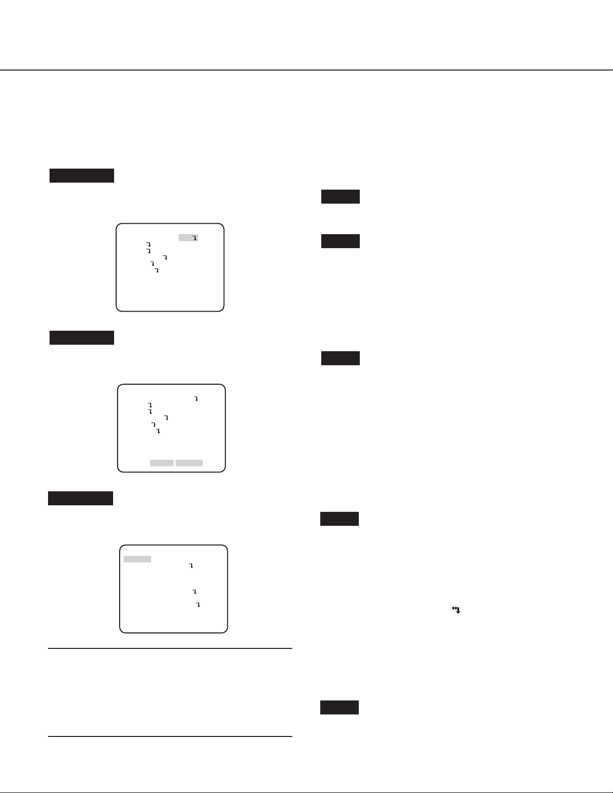
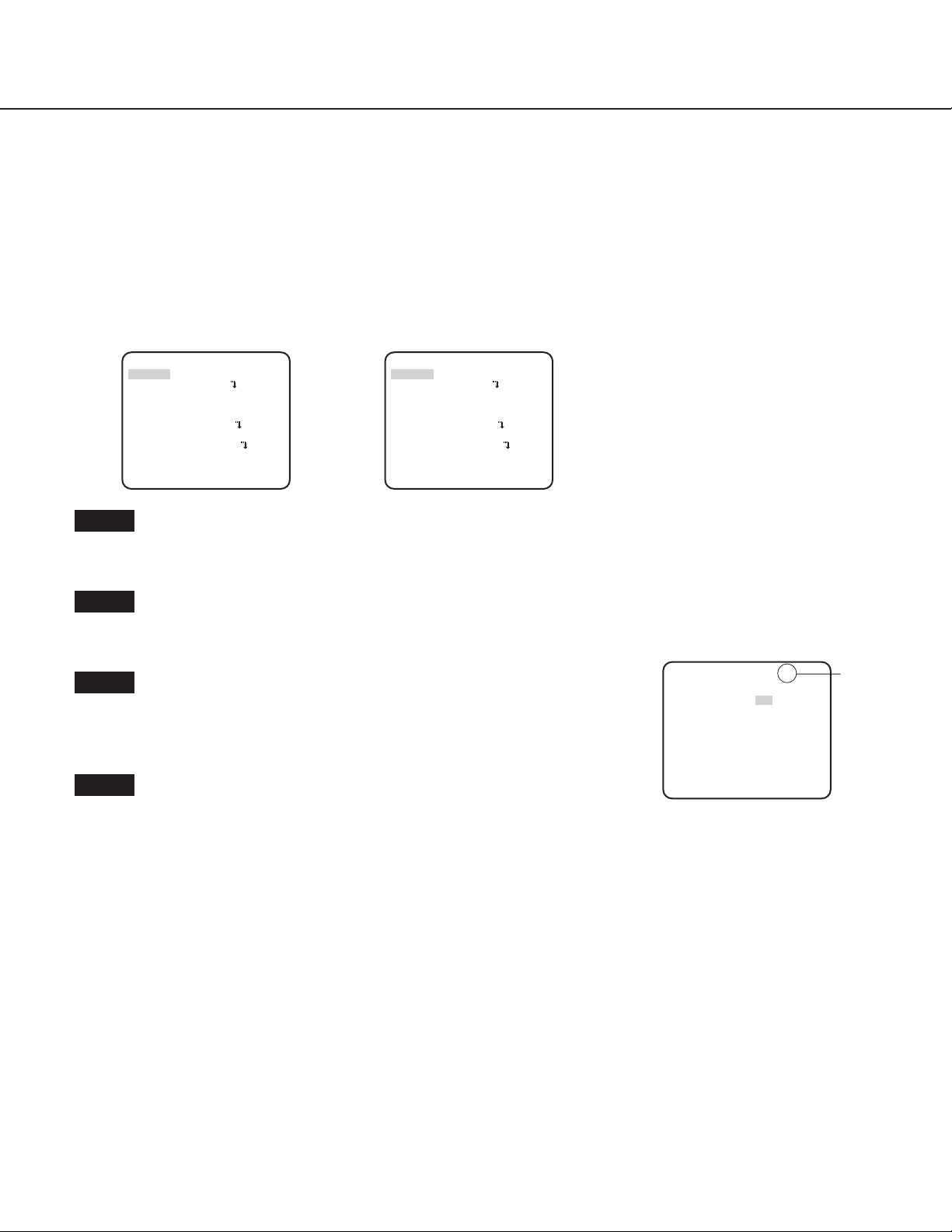
Screenshot 1
Hold down the [SET] button for about 2 seconds to call up the
top screen of the setup menu.
MODEL WV-CP630 SERIES
CAMERA ID OFF
CAMERA
SYSTEM
BACK-FOCUS
SPECIAL
LANGUAGE
END SETUP DISABIE
Screenshot 2
The setup mode changes to “ENABLE”, and the setup menu
becomes ready to be set.
MODEL WV-CP630 SERIES
CAMERA ID OFF
CAMERA
SYSTEM
BACK-FOCUS
SPECIAL
LANGUAGE
END SETUP ENABLE
Step 1
Press the [UP] or [DOWN] button to move the cursor to “END”.
Step 2
Press the [RIGHT] button to move the cursor to “SETUP”,
and press the [SET] button to change the setup mode from
“DISABLE” to “ENABLE”.
Step 3
Move the cursor to the item to be set, and press the [SET]
button.
Screenshot 3
The selected setup screen in the setup menu appears on the
screen.
**CAMERA SETUP**
SCENE1
ALC/ELC ALC
SHUTTER OFF
AGC ON(HIGH)
SENS UP OFF
WHITE BAL ATW1
DNR HIGH
D&N(IR)
AUTO1
VMD
RET TOP END
OFF
Note:
• If the top screen of the setup menu is called up with the
operation buttons while the camera is operated, the setup
mode is always “DISABLE” to prevent operation errors.
To perform settings in the setup menu, change the setup
mode to “ENABLE”.
• The cursor is a reversely highlighted part.
Step 4
Perform the settings for each item.
• Selection of setting item:
Press the [UP] or [DOWN] button to move the cursor.
• Change of settings:
Press the [RIGHT] or [LEFT] button.
• Display of advanced setup screen:
Press the [SET] button when “
” is attached to the target
setting item.
• Return to previous setup screen:
Move the cursor to “RET” and press the [SET] button.
• Return to the top screen:
Move the cursor to “TOP” and press the [SET] button, to
display the top screen of the setup menu.
Step 5
Move the cursor to “END” and press the [SET] button to return
to the camera image screen, or wait about 5 minutes and the
setup menu will automatically close.
5
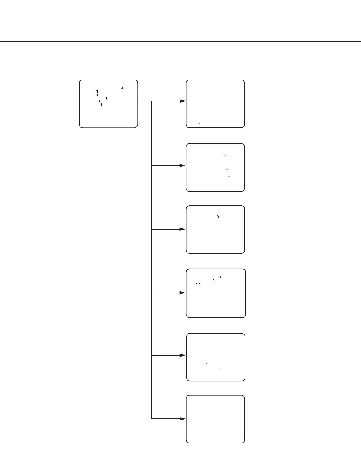
Screen transition diagram
Top screen “CAMERA ID” screen
MODEL WV-CP630 SERIES
CAMERA ID OFF
CAMERA
SYSTEM
BACK-FOCUS
SPECIAL
LANGUAGE
END SETUP DISABLE
**CAMERA ID**
0123456789
ABCDEFGHIJKLM
NOPQRSTUVWXYZ
().,'":;&#!?=
+-*/%$
SPACE POSI
RET TOP END RESET
................
“CAMERA SETUP” screen
**CAMERA SETUP**
SCENE1
ALC/ELC ALC
SHUTTER OFF
AGC ON(HIGH)
SENS UP OFF
WHITE BAL ATW1
DNR HIGH
D&N(IR)
AUTO1
VMD
RET TOP END
“SYSTEM SETUP” screen
**SYSTEM SETUP**
SYNC INT
ALARM IN/OUT
PRIVACY ZONE OFF
STABILIZER OFF
EL-ZOOM OFF
UPSIDE-DOWN OFF
LDC I...... 0
- +
OFF
RET TOP END
“BACK-FOCUS SETUP” screen
**BACK-FOCUS SETUP**
ABF PUSH SET
MANUAL-ADJ
C/L B/W AUTO
SETUP-SW LOCK OFF
NEAR FAR
.........|.........
INDICATOR XXXX
RET TOP END
“SPECIAL SETUP” screen
**SPECIAL SETUP**
CHROMA GAIN
AP GAIN
PEDESTAL
- +
DISPLAY ALARM
PIX OFF
COMMUNICATION COAX
CAMERA RESET PUSH SET
SER.NO. XXXXXXXX
RET TOP END
I..160
...
.
..I.... 20
.
... 32
.I.
“LANGUAGE SETUP” screen
**LANGUAGE SETUP**
LANGUAGE ENGLISH
6
SET
RET TOP END
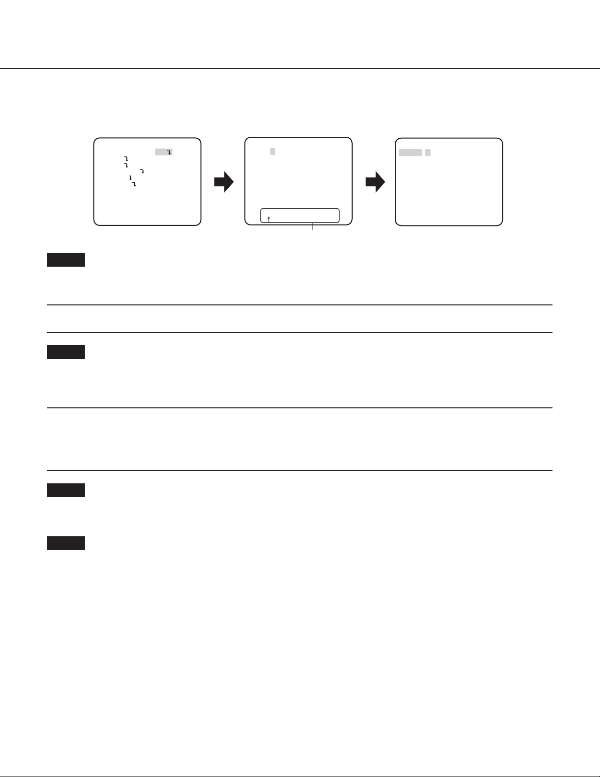
Camera title setting [CAMERA ID]
This item specified the camera title. The camera title that indicates the camera location and other information about the camera is
created with alphanumerics and symbols, and is displayed on the screen. The camera title is named with up to 16 characters.
Follow the procedure below to specify the camera title.
Top screen
MODEL WV-CP630 SERIES
CAMERA ID ON
CAMERA
SYSTEM
BACK-FOCUS
SPECIAL
LANGUAGE
END SETUP ENABLE
Step 1
Select “ON” for “CAMERA ID”, and then press the [SET] button.
The “CAMERA ID” screen appears.
→
Important:
• When “CAMERA ID” is set to “OFF”, the camera title does not appear even after setting the camera title.
“CAMERA ID” screen Display positioning screen
**CAMERA ID**
0123456789
ABCDEFGHIJKLM
NOPQRSTUVWXYZ
().,'":;&#!?=
+-*/%$
SPACE POSI
RET TOP END RESET
................
Editing area
FLOOR 1
Step 2
Move the cursor to the target item with use of the [UP], [DOWN], [RIGHT] and [LEFT] buttons, and press the [SET] button to enter the
character.
The entered characters are displayed in the editing area.
→
<Character entry>
• To revise a character, move the arrow (↑) in the editing area to a wrong character with use of the [RIGHT] or [LEFT] button, and
enter a correct character.
• To enter a blank, move the cursor to “SPACE” and press the [SET] button.
• To delete all the entered characters, move the cursor to “RESET” and press the [SET] button.
Step 3
Move the cursor to “POSI” and press the [SET] button after title entered.
→ The display positioning screen appears.
Step 4
Press the [UP], [DOWN], [RIGHT] and [LEFT] buttons to decide the title position and press the [SET] button.
The title position is specified.
→
7
Camera operation setting [CAMERA SETUP]
“SYSTEM SETUP” screen
The following describes the camera operation settings. The following settings can be configured on the “CAMERA SETUP”
screen displayed from the top screen.
Refer to page 5 for how to call up the screen.
The settings configured on the “CAMERA SETUP” screen will be saved as a scene file.
1. Register a scene file [SCENE1/SCENE2]
There are two scene modes. When strong sunshine reflection exists in the operational environment, SCENE1 is recommended; when
indoor lighting is sufficient without sunshine reflection, SCENE2 is recommended. Change between the scene files can be made by
shortcut operation. (☞ page 27) The default setting is “SCENE1”.
Screen when "SCENE1" is selected Screen when "SCENE2" is selected
**CAMERA SETUP**
SCENE1
ALC/ELC ALC
SHUTTER OFF
AGC ON(HIGH)
SENS UP OFF
WHITE BAL ATW1
DNR HIGH
D&N(IR)
AUTO1
VMD OFF
RET TOP END
Step 1
After confirming that “SCENE1” is selected, configure the settings of “ALC/ELC” through “VMD”. (☞ page 8-17)
To change the scene files, go to step 2.
**CAMERA SETUP**
SCENE2
ALC/ELC ALC
SHUTTER OFF
AGC ON(HIGH)
SENS UP OFF
WHITE BAL ATW1
DNR HIGH
D&N(IR)
AUTO1
VMD OFF
RET TOP END
Step 2
Move the cursor to “SCENE1” and press the [RIGHT] or [LEFT] button to select “SCENE2”.
The screen changes and displays “SCENE2”.
→
Step 3
Set the items you want to change.
The number displayed at the right side of the title on each setting screen indicates a scene file
**ALC CONT**(1)
BACK LIGHT COMP
SUPER-D6
HLC
--FOG COMP
---
ON
Scene file
number
number.
LEVEL .I..... 0
- +
Step 4
RET TOP END
Move the cursor to “SCENE2” and press the [RIGHT] or [LEFT] button to select “SCENE1” to
resume normal operation.
2. Light quantity control method selection [ALC/ELC]
The method of controlling the quantity of light is selected from the following in accordance with the lens to be used.
ALC (default): The iris of the lens is automatically adjusted in accordance with the brightness of a subject. Select “ALC” when using
an ALC lens.
ALC+: Controls the quantity of light with a combination of the electronic shutter and auto iris. This selection is suitable at shooting
a bright subject such as an outdoor subject with auto iris lens. Be aware that flicker may occur when a subject is under
fluorescent lighting.
ELC: Controls the quantity of light with the electronic shutter. This selection is suitable for use of a lens with fixed iris or manual iris.
8
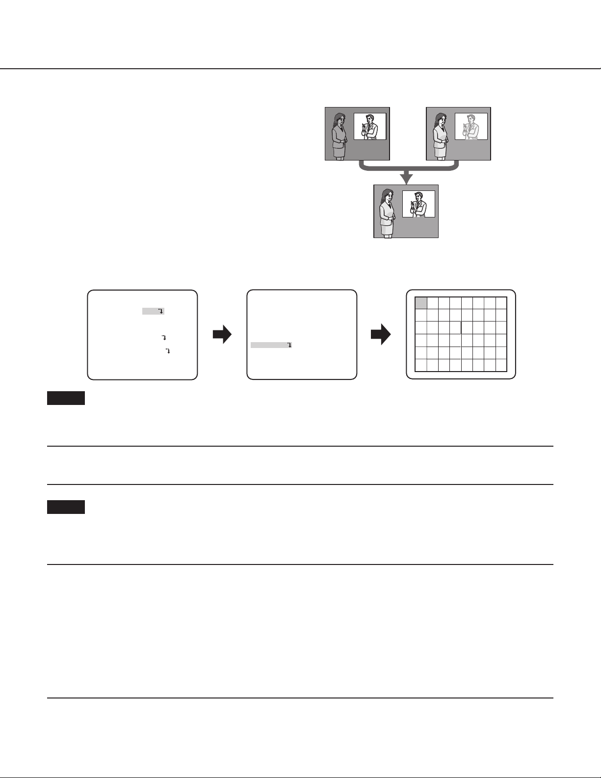
About Super Dynamic 6 Functions
Subject in the dark
Subject in the bright
If there is high contrast between the bright and dark areas
in a shooting zone, the dark area becomes less visible
because the camera adjusts the iris in accordance with the
bright area. Conversely, adjusting the lens brightness for the
darker areas causes the brighter areas to become washed
out. The SUPER DYNAMIC 6 function digitally combines
an image that is set up for a clear view of the brighter areas
with an image that is set up for a clear view of the darker
areas, creating a final image that preserves overall detail.
SUPER-D6 setting
When "ALC/ELC" is set to "ALC", the SUPER-D6 function is available.
Follow the procedure below.
area is hard to notice.
area is hard to notice.
Creates a clearer
image by digitally
combining images
Mask setting screen“CAMERA SETUP” screen
**CAMERA SETUP**
SCENE1
ALC/ELC ALC
SHUTTER OFF
AGC ON(HIGH)
SENS UP OFF
WHITE BAL ATW1
DNR HIGH
D&N(IR)
VMD OFF
RET TOP END
AUTO1
“ALC CONT” screen
**ALC CONT**(1)
BACK LIGHT COMP
SUPER-D6
HLC
OFF
FOG COMP
OFF
MASK SET
LEVEL .I..... 0
- +
RET TOP END
OFF
Step 1
Set “ALC/ELC” to “ALC”, and press the [SET] button.
The “ALC CONT” screen appears.
→
Note:
• When “ALC/ELC” is set to “ELC” or “ALC+” and the [SET] button is pressed, the “ELC CONT” or “ALC+ CONT” screen will appear.
• When “ELC” or “ALC+” is selected, the SUPER-D6 function is disabled. “---” appears and “OFF” is selected. (Go to Step 3)
Step 2
Move the cursor to "SUPER-D6" and select the "ON" or "OFF".
ON (default): Activates the SUPER-D6 function. (Go to Step 6)
OFF: Deactivates the SUPER-D6 function. (Go to Step 3)
Note:
• Once the “SUPER-D6” function is set to “ON”, the settings of the following items will be restricted.
SHUTTER: It can only be set to “OFF” or “1/120”.
SENS UP: It can only be set to “OFF” or “AUTO”.
• Once the “SUPER-D6” function is set to “ON”, a shadow (black line) may appear at the border of the brighter part and darker
• When flickering or noise is observed frequently due to the illumination of light, select “OFF”.
• When flickering or color deterioration is observed
• When noise is produced in a bright area on the screen
• Once the “SUPER-D6” function is set to “ON”, “---” is displayed for “HLC” and “FOG COMP”. In this case, the “HLC” and “FOG
part. This is not a fault.
COMP” functions cannot be set.
9
 Loading...