

Panasonic WV-CP480, WV-CP484E User Manual
SUPER-D3 ON: Enables SUPER-D3 to compensate backlight automatically.
SUPER-D3 OFF: Enables manual setting to compensate backlight.
Notes:
• When set to ON, the available parameters for SHUTTER and SENS UP will be limited
as shown on the next page.
•Set SUPER-D3 to OFF when noise in a bright portion, flickerings, or colour deterioration are observed.
1. Select ALC for ALC/ELC on the CAMERA SETUP menu
and press SET.
→ The ALC CONT menu opens.
2. Select ON for SUPER-D3.
3. Adjust the video output level (LEVEL) by moving the "I"
cursor. It may be better to adjust LEVEL slightly higher.
First, select a language for menu display and camera ID display.
Language Setup (LANGUAGE SETUP)
1. Select LANGUAGE on the top menu and press SET.
→ The LANGUAGE SETUP menu opens.
2. Select a language. The default setting is English.
Available languages: ENGLISH, FRANÇAIS,
DEUTSCH, ESPAÑOL, ITALIANO, кмллдав
,
JAPANESE, CHINESE
3. Select SET on the menu and press the SET button.
1. Camera Identification Setting (CAMERA ID)
Assign a name to the camera using up to 16 characters to
display it overlaying on the camera picture in the selected
position.
Note: If you change the language selection after the
assignment of camera ID, it will be erased.
1. On the CAMERA SETUP menu, select ON
↓ or OFF↓
for CAMERA ID and press SET.
ON↓: Displays entered camera ID.
OFF↓: Does not display the ID.
→The CAMERA ID menu opens.
2. Select a character from the character area
and press SET.
→ The selected characters are displayed in
the editing area.
3. Repeat these procedures until all characters
are entered.
• To enter a blank space, select SPACE and
press SET.
• To replace a specific character in the editing
area:
1. Move the cursor to the editing area and
then move the pointer to the character to
be replaced pressing the L and R buttons.
2. Move the cursor to a candidate character
in the character area and press SET.
• To erase all characters of the camera ID,
select RESET and press SET.
4. To specify the ID display position:
1. Select POSI and press SET.
→ The entered camera ID will be highlighted on the screen.
2. Move it into the appropriate position and press SET.
→ The position is determined and the screen will return to the CAMERA ID menu.
Note: Keep pressing any of L/R/U/D for a second or more to move the camera ID
faster as necessary.
2. Light Control Mode Setting (ALC/ELC)
Select a light control mode depending on the lens type mounted. The default setting is ALC.
ALC↓: Is applicable to the auto iris lens. SUPER-D3 is available with this selection.
ELC↓: Is applicable to the fixed or manual iris lens.
Cautions:
1. Under bright lighting conditions such as outdoors, use an ALC lens because the ELC
control range is not wide enough under these conditions.
2. Use an ALC type lens if the following phenomena occur:
• Strong smear and/or blooming on highlighted objects such as a spotlight or sunlight
from windows.
• Noticeable flicker in the picture and/or colour rendition variations.
3. If ELC is selected, SUPER-D3 and SHUTTER are not available and the white balance
mode is automatically set to ATW1 or ATW2 previously set.
4. If ELC is selected and a fixed iris lens is used, the focal depth becomes shallower
than with the use of an ALC lens. Therefore, the range of focus-to-object distance
becomes narrower.
2-1. ALC Mode with SUPER-D3 ON
Super Dynamic 3 Function (SUPER-D3)
In the SUPER-D3 mode, more photometric weight is given to the centre of the screen than to
the edge where a bright backlight would most likely be located.
(To be continued reverse page)
SETTING PROCEDURES
Highlighted
Character
Cursor
Pointer
Character
Area
Command
Editing
Area
NighttimeNighttime DaytimeDaytime
SUPER-D3 ON SUPER-D3 OFF
Opening/Closing the Setup Menu
It is possible to open the WV-CP480 TOP menu by
holding down the SET button for 2 seconds or more
while displaying camera pictures.
At first, the menu will be displayed in English. Move
the cursor to SETUP DISABLE using the direction
buttons and press the SET button to change it to
SETUP ENABLE so that the menu becomes operable
in selecting your language and other parameters.
On the menu, you can check current settings and
perform settings to meet requirements.
To close the menu and return to camera picture, move the cursor to END and press the SET
button.
How to Set Up on the Menu
Operate the direction buttons (U: Up, D: Down,
L: Left, R: Right) and the SET button as shown
in the table below.
In the following pages, abbreviated expressions
will be used many times for convenience.
An abbreviated expression "Select CAMERA
and press SET" means "Move the cursor to
CAMERA by using the Up or Down button
and press the SET button." Buttons of LEFT,
UP, RIGHT, and DOWN are abbreviated as
L, U, R, and D respectively.
Function/Button Up(U) Down (D) Right (R) Left (L) Set(SET)
Open the menu NA NA NA NA Press 2 seconds
Move the cursor ↑↓→←NA
Select a setup item ↑↓NA NA NA
Select a parameter NA NA →← NA
Apply settings NA NA NA NA Press
Open a sub-menu (Move the cursor to the item with ↓.) Press
Close the menu (Move the cursor to END.) Press
Return to the previous menu (Move the cursor to RET.) Press
Return to the top menu (Move the cursor to TOP.) Press
Reset a specific item (Move the cursor to the item to be reset , press L and R simultaneously.)
Reset all*
1
(When camera picture is displayed, press L and R for 2 seconds.)
Enable/Disable the menu *
2
(Move the cursor to SETUP DISABLE/ENABLE, press SET)
Scroll up or down the page (Hold down ↑ or ↓)
Notes:
•NA: Not Applicable.
• *1 "Reset all" is an irrevocable procedure that resets all settings to the default values.
We recommend that you take note of settings before executing this command.
• *2 Before operating the menu, change SETUP DISABLE (default setting) to
SETUP ENABLE.
•When closing the menu, the changed settings will be stored in the memory of the
camera and will remain until the settings are overwritten by new ones.
•Use a system controller to operate setup menus after installation as necessary. Almost
all operations will be available unless otherwise mentioned.
Top Menu and Sub Menus
The following menus will be displayed in the language selected on the LANGUAGE SETUP
menu.
There are four sub menus selectable on the top menu: CAMERA SETUP (2 pages), BACKFOCUS SETUP, SPECIAL SETUP, and LANGUAGE SETUP. On these menus, select a setup
item followed by "
↓" and press the SET button to open more sub menus.
ABOUT SETUP MENUS
■ Connections
Notes:
•Before connecting the power cables, be sure to remove the protection screw for transportation. Otherwise, the camera can be damaged.
• Firmly connect the power cord.
•When the camera is mounted on a pan/tilt table, the power cord should be long enough.
Otherwise, it may be unplugged from the camera.
• Connection of 220 V - 240 V AC 50 Hz to WV-CP480
For processing of the mains lead, read the warning text on the first page.
Plug the supplied power cord to the inlet of the
camera.
• Connection of 12 V DC/24 V AC 50 Hz to WV-CP484E
12 V DC
Use the formula below to calculate the power cable and power supply. The voltage supplied to the power terminals of the camera should be within
10.8 V DC and 16 V DC.
10.8 V DC ≤ VA − 2(R x I x L) ≤ 16 V DC
L: Cable length (m)
R: Resistance of copper wire (Ω/m)
V
A : DC output voltage of power supply unit
I: DC current consumption (A). See specifications.
Resistance of copper wire [at 20 °C]
24 V AC
The recommended cable length and thickness are shown in
the table for reference. The voltage supplied to the power
terminals of the camera should be within
19.5 V AC and
28 V AC.
• Video Cable Connections
GEN-LOCK Input
Connect an external sync source to the
GEN-LOCK input connector. When looping through, use a branch connector
(not supplied). Set the termination switch
to 75 Ω when the camera is at the line
end, or set it to HI-Z in other cases.
VIDEO OUT
Connect the video output connector to the monitor or other system device with the procured coaxial cable. The maximum extensible length is shown in the table.
• External Terminal Connections
ALARM OUT
Connect an external device such as a buzzer, recorder, etc.
Specifications are: open collector output: 16 V DC, 100 mA max.
OFF: High, inactive
ON: Low, active
DAY/NIGHT IN
Connect an external device such as an optical sensor.
Specifications are: pulled-up input: 5 V DC,
2 mA min.
OFF: Open contact, inactive
ON: Closed contact, active
Notes:
• To validate the sensor inputs, select EXT
for BW on the BW MODE menu.
•Use a relay unit if the voltage or current of the connected device exceeds the ratings.
■ Lens Mounting and Adjustment
Installation of Auto Iris Lens Connector
Install the supplied lens connector when using a video-driven ALC lens.
(1) Cut the iris control cable at the edge of the existing lens connector and process the cable
end as shown in the figure.
Cautions:
1. The installation should be made by qualified service personnel or system installers.
2. The connections should comply with all local codes.
3. ONLY CONNECT THIS TO 24 V AC CLASS 2 POWER SUPPLY. Be sure to connect the
grounding lead to the GND terminal. (For WV-CP484E)
4. To prevent fire or electric shock hazard, use a UL listed cable (VW-1, style 1007) for
the Input Terminal. (For WV-CP484E)
5. Do not use a transformer larger than 10VA. (For WV-CP484E)
6. Read the WARNING text about the colours of the wire in the mains lead described on
the first page. (For WV-CP480)
INSTALLATION
Copper wire
size (AWG)
Resistance
Ω/m
#24
(0.22 mm
2
)
0.078
#22
(0.33 mm
2
)
0.050
#20
(0.52 mm
2
)
0.03
#18
(0.83 mm
2
)
0.018
Copper wire
size (AWG)
Length (m)
#24
(0.22 mm
2
)
20
#22
(0.33 mm
2
)
30
#20
(0.52 mm
2
)
45
#18
(0.83 mm
2
)
75
Type of coaxial cable
Recommended
maximum
cable length
RG-59/U
(3C-2V)
250
RG-6/U
(5C-2V)
500
RG-11/U
(7C-2V)
600
RG-15/U
(10C-2V)
800
(m)
Optical sensor
Recorder,
Buzzer, etc.
DAY/
NIGHT
ALARM
IN
GND
OUT
GND
Mounting the Camera
• Mounting from the Top
Remove the mount adapter from the bottom
of the camera by removing the two fixing
screws. Attach the mount adapter to the top
as shown in the figure, then mount the camera on the mounting bracket.
Caution:
Be sure to use two original fixing screws for
the mount adapter.
Longer screws may damage the inner components. Or shorter screws may cause the
camera to fall down.
Flange-back (Back-focus) Adjustment
Before adjustment, read the Hints column below.
This adjustment is available only if SETUP-SW LOCK is set to OFF in the BACK-FOCUS
SETUP menu.
1. Aim the camera at the targeting objects and if applicable adjust the zoom angle.
2. Press the SET button.
→ A bar graph with "I" cursor and INDICATOR (4-digit number) will be overlaid on the
camera picture.
→ Back focus will be automatically adjusted.
3. If needed, perform manual adjustment using
the L and R buttons to obtain the best focus
on the targeted object while observing the
picture. See INDICATOR for reference.
The bar graph will disappear if no operation is
performed for around 10 seconds.
This adjustment can be also performed on the
setup menu.
Refer to 16. Back-focus Setting for details.
Important: Do not use the ABF function for continuous or repetitive purposes (ex. auto-focus
etc.). This function is to be used to correct defocus caused by switching between colour
and black - and - white when/after installing the camera.
(2) Solder the lens cable to the pins of the sup-
plied connector.
The pin assignment is as follows.
Pin 1: Power source; +9 V DC, 50 mA max.
Pin 2: Not used
Pin 3: Video signal; 0.7 V[P-P]/40 kΩ
Pin 4: Shield, ground
Caution for Mounting the Lens
Follow the directions shown in the figure for the
protrusion between a lens and the camera
body. This camera has a mount for use with the
CS-mount lens shipped from the factory.
Purchase and use the optional C-mount adapter
when using the C-mount lens.
A lens less than 450
g can be mounted on the
camera. If the lens is heavier, both the lens and
camera should be secured by the supporter.
Mounting the Lens
1. Attach the optional C-mount adapter when
using a C-mount lens.
2. Mount the lens.
3. Connect the lens cable to the auto iris connector on the side of the camera.
Pin 3
Pin 4
Pin 2
Rib
Pin 1
Fixing Screws
Mount Adapter
C-mount: Less than 13 mm
CS-mount: Less than 8 mm
C-mount Adapter
(Option)
Lens Mount
Not larger than ø20 mm
6 mm
2 mm
Hints
Before Back-focus Adjustment
•Adjustment procedures vary depending on the lens. Refer to the instructions included with the lens.
•Reset the back-focus by pressing the L and R buttons simultaneously on the camera, and adjust the back-focus.
•Move the lens focus to the FAR-end when using a fixed-focal lens (lens focus
adjustable type), and adjust the back-focus.
For Adjusting the Focus
• It is recommended that you lower the lighting for the object to be as dim as possible when adjusting the focus with an auto iris lens. This will make the iris open and
will result in an accurate focus even though the lighting conditions vary. This may
be slightly different from the best focus point in a specific lighting condition.
•Compared with cases under visible lights, using near-infrared lights may somewhat
deviate the focus. It is recommended that you select AUTO or PRESET for C/L
← →
B/W in the BACK-FOCUS SETUP menu to obtain a proper focus for each of visible
and near-infrared lights.
For Using General Vari-focal Lenses
1. Aim at the objects 10 meters away or more to adjust the back-focus.
2. For 8x and 10x class lenses, set the zoom to the WIDE-end and the focus to the
FAR-end, and then adjust the back focus.
3. For 2x and 3x class lenses, set the zoom to the TELE-end and the focus to the FARend, and then adjust the back focus.
4. Aim the camera at the targeted objects to place them in the center then coarsely
adjust the zoom angle and the focus of the lens. Finally, perform adjustment of the
back-focus in either ways of using ABF (automatically) or MANUAL-ADJ (manually).
Note: There may be lenses having an extended range in lens focus adjustment, except
Panasonic lenses. When using such a lens, set the lens focus back appropriately
from the applicable end position in the above step 2 and 3 depending on the lens,
and then perform back-focus adjustment. The back-focus will not be properly
adjusted if the lens focus is positioned into the extended range.
• Auto-Back-Focus (flange back adjustment):
1-push adjustment (local/remote), manual adjustment (local/remote), automatic
adjustment at BW/CL transition
• Light control: ALC (DC/Video), ELC
• Terminals: Alarm output, Day/night sensor input
• Miscellaneous: Privacy zone setting,
Video motion detection, etc.
FEATURES
Before attempting to connect or operate this product,
please read these instructions carefully and save this manual for future use.
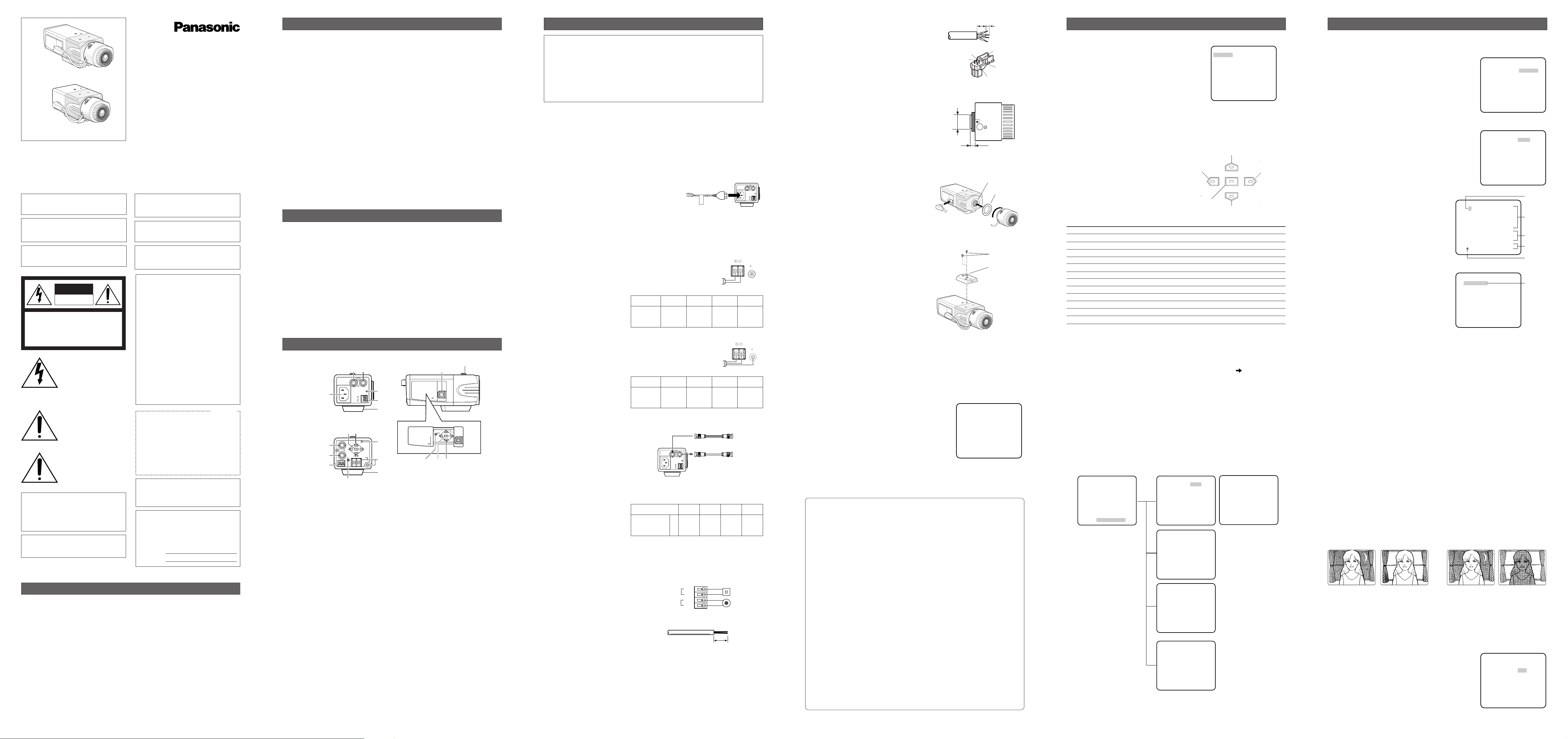
MAJOR OPERATING CONTROLS AND THEIR FUNCTIONS
q AC Inlet (220 V - 240 V AC 50 Hz)
<WV-CP480 only>
Is connected by the supplied power
cord.
q Power Input Terminal (DC 12 V IN, AC
24 V IN, GND) <WV-CP484E only>
Receives 24 V AC or 12 V DC from the
power supply.
w Gen-lock Input Connector
(GEN-LOCK)
Receives sync source signal from an
external device.
e Video Output Connector
(VIDEO OUT)
Supplies the video output to the system
devices.
r Power Indicator (POWER)
Is lit when the power is supplied.
t Alarm Output Terminal
(ALARM OUT/GND)
Supplies the alarm output signal to the
alarm input connector of an external
device when the camera detects motion.
(Open collector output: 16 V DC,
100 mA max).
y Day/Night Input Terminal (DAY/NIGHT
IN/GND)
Is connected to an external sensor to
receive day/night detection signals.
u Camera Mounting Adapter
Is used to mount the camera onto a
bracket.
i Auto Iris Lens Connector
Is connected by the auto iris lens connector (4-pin male) supplied with the
camera.
o Gen-lock Termination Switch
(HI-Z G/L 75Ω)
Is used to terminate the line with a 75 Ω
when the camera is at the line end.
!0 Set Button ((SET) ABF/MENU)
Adjusts the back focus by pressing this
button while displaying camera pictures
(ABF: Automatic Back Focus). Refer to
ABOUT SETUP MENUS for setup operations.
!1 Direction Buttons ((LEFT) NEAR,
(RIGHT) FAR, (UP), (DOWN))
In the back-focus adjustment, the LEFT
and RIGHT buttons are used for manual
adjustment. Refer to ABOUT SETUP
MENUS for setup operations.
N0105-1035 3TR003298BAA Printed in Japan
The side panel is provided for the WV-CP480 only.
Slide the panel to the left until it locks.
Colour CCTV Camera
Operating Instructions
(Lens: Option)
WV-CP480
Model Nos.
WV-CP484E
LIMITATION OF LIABILITY
IN NO EVENT SHALL MATSUSHITA ELECTRIC INDUSTRIAL CO., LTD. BE LIABLE TO ANY
PARTY OR ANY PERSON, EXCEPT FOR REPLACEMENT OR REASONABLE MAINTENANCE
OF THE PRODUCT, FOR THE CASES, INCLUDING BUT NOT LIMITED TO BELOW:
(1) ANY DAMAGE AND LOSS, INCLUDING WITHOUT LIMITATION, DIRECT OR INDIRECT,
SPECIAL, CONSEQUENTIAL OR EXEMPLARY, ARISING OUT OF OR RELATING TO THE
PRODUCT;
(2) PERSONAL INJURY OR ANY DAMAGE CAUSED BY INAPPROPRIATE USE OR NEGLI-
GENT OPERATION OF THE USER;
(3) UNAUTHORIZED DISASSEMBLY, REPAIR OR MODIFICATION OF THE PRODUCT BY
THE USER;
(4) INCONVENIENCE OR ANY LOSS ARISING WHEN IMAGES ARE NOT DISPLAYED, DUE
TO ANY REASON OR CAUSE INCLUDING ANY FAILURE OR PROBLEM OF THE PRODUCT;
(5) ANY PROBLEM, CONSEQUENTIAL INCONVENIENCE, OR LOSS OR DAMAGE, ARISING
OUT OF THE SYSTEM COMBINED BY THE DEVICES OF A THIRD PARTY;
(6) ANY CLAIM OR ACTION FOR DAMAGES, BROUGHT BY ANY PERSON OR ORGANIZA-
TION BEING PHOTOGENIC SUBJECT, DUE TO VIOLATION OF PRIVACY WITH THE
RESULT OF THAT SURVEILLANCE-CAMERA’S PICTURE, INCLUDING SAVED DATA,
FOR SOME REASON, THAT BECOMES PUBLIC OR IS USED FOR THE PURPOSE
OTHER THAN SURVEILLANCE;
WV-CP480
WV-CP484E
Panasonic’s WV-CP480 series cameras introduce a new level of high picture quality by use
of Super-Dynamic 1/3 inch CCD and digital signal processing LSIs.
• Super Dynamic: 128x with zone-free
brightness detection
• High sensitivity: 0.08 lx in B/W mode,
0.6 lx in colour mode (F1.4 Sens-up
OFF)
• High resolution: 540 lines typical, 520
lines minimum
• Sensitivity enhancement: Up to 10x
AUTO/32x FIX
• Synchronization:
VD2/ LINE-LOCK/VBS/VS/INTERNAL
1. Do not attempt to disassemble the camera.
To prevent electric shock, do not remove screws or covers.
There are no user-serviceable parts inside. Ask qualified service personnel for servicing.
2. Handle the camera with care.
Do not abuse the camera. Avoid striking, shaking, etc. The camera could be damaged
by improper handling or storage.
3. The installation should be made by qualified service personnel or system installers.
4. Do not use strong or abrasive detergents when cleaning the camera body.
Use a dry cloth to clean the camera when dirty. When the dirt is hard to remove, use a
mild detergent and wipe gently. Then wipe off the remaining detergent with a dry cloth.
5. Clean the CCD faceplate with care.
Do not clean the CCD with strong or abrasive detergents. Use lens tissue or a cotton
tipped applicator and ethanol.
6. Never face the camera towards the sun.
Do not aim the camera at bright objects. Whether the camera is in use or not, never aim
it at the sun or other extremely bright objects. Otherwise, blooming or smears may be
caused.
7. Do not operate the camera beyond the specified temperature, humidity or power
source ratings.
Use the camera at temperatures within –10 °C to +50 °C, and humidity below 90 %. The
input power source is 220 V - 240 V AC 50 Hz for WV-CP480 and 24 V AC 50 Hz/12 V DC
for WV-CP484E.
8. Avoid connections during a lightning storm.
Otherwise, an electric shock may be caused.
PRECAUTIONS
Protection screw for
transportation
Turn the power off at the mains
to disconnect the main power
for all unit.
The lightning flash with arrowhead symbol, within an equilateral triangle, is intended to
alert the user to the presence
of uninsulated "dangerous voltage" within the product's enclosure that may be of sufficient
magnitude to constitute a risk
of electric shock to persons.
The serial number of this product may be found
on the surface of the unit.
You should note the serial number of this unit
in the space provided and retain this instruction
as a permanent record of your purchase to aid
identification in the event of theft.
Model No.
Serial No.
WARNING:
To prevent fire or electric shock hazard, do not
expose this appliance to rain or moisture. The
apparatus shall not be exposed to dripping or
splashing and that no objects filled with liquids,
such as vases, shall be placed on the apparatus.
CAUTION: TO REDUCE THE RISK OF ELECTRIC SHOCK,
DO NOT REMOVE COVER (OR BACK).
NO USER-SERVICEABLE PARTS INSIDE. REFER SER-
VICING TO QUALIFIED SERVICE PERSONNEL.
CAUTION
RISK OF ELECTRIC
SHOCK DO NOT OPEN
The exclamation point within
an equilateral triangle is intended to alert the user to the presence of important operating
and maintenance (servicing)
instructions in the literature
accompanying the appliance.
FOR YOUR SAFETY PLEASE READ THE FOLLOWING TEXT CAREFULLY.
WARNING: This apparatus must be earthed.
IMPORTANT
The wires in this mains lead are coloured in accordance with the following code.
Green-and-yellow: Earth
Blue: Neutral
Brown: Live
As the colours of the wire in the mains lead of
this appliance may not correspond with the coloured
markings identifying the terminals in your plug, proceed as follows.
The wire which is coloured
green-and-yellow
must be connected to the terminal in the plug which
is marked with the letter
E or by the earth symbol I
or coloured green or green-and-yellow.
The wire which is coloured
blue must be connected to the terminal in the plug which is marked
with the letter
N or coloured black.
The wire which is coloured
brown must be connected to the terminal in the plug which is marked
with the letter
L or coloured red.
Wij verklaren als enige aansprakelijke, dat het product
waarop deze verklaring betrekking heeft, voldoet aan de
volgende normen of andere normatieve documenten,
overeenkomstig de bepalingen van Richtlijnen 73/23/EEC
en 89/336/EEC.
Vi erklærer os eneansvarlige for, at dette produkt, som
denne deklaration omhandler, er i overensstemmelse
med standarder eller andre normative dokumenter i følge
bestemmelserne i direktivene 73/23/EEC og 89/336/EEC.
Vi deklarerar härmed värt fulla ansvar för att den produkt
till vilken denna deklaration hänvisar är i
överensstämmelse med standarddokument, eller andra
normativa dokument som framstölls i EEC-direktiv nr.
73/23 och 89/336.
Ilmoitamme yksinomaisella vastuullamme, että tuote, jota
tämä ilmoitus koskee, noudattaa seuraavia standardeja
tai muita ohjeellisia asiakirjoja, jotka noudattavat
direktiivien 73/23/EEC ja 89/336/EEC säädöksiä.
Vi erklærer oss alene ansvarlige for at produktet som
denne erklæringen gjelder for, er i overensstemmelse
med følgende normer eller andre normgivende
dokumenter som følger bestemmelsene i direktivene
73/23/ EEC og 89/336/EEC.
We declare under our sole responsibility that the product
to which this declaration relates is in conformity with the
standards or other normative documents following the
provisions of Directives EEC/73/23 and EEC/89/336.
THIS APPARATUS MUST BE EARTHED.
To ensure safe operation the three-pin plug supplied
must be inserted only into a standard three-pin power
point which is effectively earthed through the normal
household wiring. Extension cords used with the
equipment must be three-core and be correctly wired
to provide connection to earth. Wrongly wired extension cords are a major cause of fatalities.
The fact that the equipment operates satisfactorily
does not imply that the power point is earthed and that
the installation is completely safe. For your safety, if in
any doubt about the effective earthing of the power
point, consult a qualified electrician.
For Australia
CAUTION:
Before attempting to connect or operate this
product, please read the label on the surface of
the unit.
CAUTION:
An ALL-POLE MAINS SWITCH with a contact
separation of at least 3 mm in each pole shall
be incorporated in the electrical installation of
the building.
i
G /L75Ω
Hi-Z
(UP)
ABF/MENU
NEAR
FAR
(RIGHT)
(SET)
(LEFT)
(DOWN)
<WV-CP480>
ew
220-240V ~ 50Hz
GEN-LOCK VIDEO OUT
POWER
q
GND
ALARM
OUT
GND
DAY/
NIGHT
r
IN
t
u
<WV-CP484E>
!0 !1
POWER
t
e
w
y
VIDEO OUT
NEAR
(LEFT) (RIGHT)
GEN-LOCK
Hi-Z
G /L75Ω
ABF/MENU
(SET)
1 - 2 - DC12V IN
1 - 2 - AC24V IN
(UP)
(DOWN)
r
FAR
GND
q
u
o
y
o!0 !1
220-240V ~ 50Hz
220 V - 240 V AC
50 Hz
12 V DC
GEN-LOCK VIDEO OUT
GND
ALARM
OUT
GND
DAY/
NIGHT
Recommended Wire
AWG 22 - 28, single or stranded wire
POWER
IN
BNC
BNC
24 V AC
9 - 10 mm
BNC
BNC
220-240V ~ 50Hz
- DC 12V IN
- AC 24V IN
12
+
–
12
From
Sync Source
(VBS/VS)
To Video IN
(CAMERA IN)
GEN-LOCK VIDEO OUT
POWER
GND
ALARM
OUT
GND
DAY/
NIGHT
IN
GND
- DC 12V IN
- AC 24V IN
GND
MODEL WV-CP480 SERIES
↵
CAMERA
BACK-FOCUS
SPECIAL
LANGUAGE
END SETUP DISABLE
↵
↵
↵
Left Button
NEAR FAR
(LEFT) (RIGHT)
Set Button
Down Button
Up Button
ABF/MENU
(SET)
(UP)
(DOWN)
Right Button
CAMERA ID
0123456789
ABCDEFGHIJKLM
NOPQRSTUVWXYZ
().,'":;&#!?=
+-*/%$
SPACE POSI
RET TOP END RESET
................
W
V
-
C
**LANGUAGE SETUP**
LANGUAGE ENGLISH
SET
RET TOP END
**CAMERA SETUP** 1/2
CAMERA ID OFF
ALC/ELC ALC
SHUTTER OFF
AGC ON(HIGH)
SENS UP OFF
SYNC INT
WHITE BAL ATW1
MOTION DET OFF
DNR HIGH
RESOLUTION HIGH
BW MODE
P
4
8
0
↵
↵↵
↵
SETUP DISABLE SETUP ENABLE
NEAR FAR
.........I..........
INDICATOR 9999
MODEL WV-CP480 SERIES
↵
CAMERA
BACK-FOCUS
SPECIAL
LANGUAGE
END SETUP ENABLE
↵
↵
↵
**CAMERA SETUP** 1/2
CAMERA ID OFF
ALC/ELC ALC
SHUTTER OFF
AGC ON(HIGH)
SENS UP OFF
SYNC INT
WHITE BAL ATW1
MOTION DET OFF
DNR HIGH
RESOLUTION HIGH
BW MODE
↵
**BACK-FOCUS SETUP**
ABF
MANUAL-ADJ
← →
B/W AUTO
C/L
SETUP-SW LOCK OFF
NEAR FAR
.........I..........
INDICATOR 9999
RET TOP END
→
PUSH SW
↵
↵↵
↵
**CAMERA SETUP** 2/2
PRIVACY ZONE OFF
MIRROR OFF
LENS-DRIVE DC
STABILIZER OFF
RET TOP END
**SPECIAL SETUP**
CHROMA GAIN .....I...
AP GAIN ...I.....
PEDESTAL .....I...
- +
PIX OFF
COMMUNICATION COAX
CAMERA RESET
SER.NO. XXXXXXXX
RET TOP END
↵
→
PUSH SW
**LANGUAGE SETUP**
LANGUAGE ENGLISH
SET
RET TOP END
**ALC CONT**
BACK LIGHT COMP
SUPER-D3 ON
LEVEL ..I......
- +
RET TOP END
STANDARD ACCESSORIES
Operating Instructions (this document).......................1 pc.
The following are for installation.
ALC Lens Connector (YFE4191J100)..........................1 pc.
AC Power Cord (for WV-CP480)..................................1 pc.
Pick-up device: 752 (H) x 582 (V) pixels, interline transfer CCD
Scanning area: 4.8 (H) x 3.6 (V) mm (Equivalent to scanning area of
1/3" pick-up tube)
Scanning: 625 lines/50 fields/25 frames
Horizontal: 15.625 kHz
Vertical: 50 Hz
Synchronization: Multiplexed vertical drive (VD2), Line-locked,
VBS/ VS, or Internal
GEN LOCK input VBS/VS 1.0 V[P-P] composite 75 Ω/BNC connector
Video output: 1.0 V[P-P] PAL composite 75 Ω/BNC connector
Resolution: Horizontal 480 lines (C/L Normal), 540 lines typ.,
520 lines min. (C/L High), 570 lines (B/W)
Vertical 400 lines (at centre)
Signal-to-noise ratio: 50 dB (Equivalent to AGC Off, weight On)
Dynamic range: 54 dB typ
Minimum illumination: 0.6 lx {0.06 footcandle} at F1.4 (C/L),
0.5 lx {0.05 footcandle} at F1.2 (C/L),
0.08 lx {0.008 footcandle} at F1.4 (B/W),
0.06 lx {0.006 footcandle} at F1.2 (B/W)
Lens mount: CS-mount
Major items on menu setup
Language: English, French, German, Spanish, Italian,
Japanese, Russian, or Chinese
Camera ID: Up to 16 characters
Light control ALC/ELC
Super Dynamic 3: ON or OFF
Electronic shutter speed: 1/50 (OFF), 1/120, 1/250, 1/500, 1/1 000,1/2 000,
1/4 000, 1/10 000 s
Gain control: ON (HIGH), ON (MID), ON (LOW), or OFF
Sensitivity enhancement: OFF, x2AUTO, x4AUTO, x6AUTO, x10AUTO, x2FIX,
x4FIX, x6FIX, x10FIX, x16FIX, x32FIX
White balance: ATW1, ATW2, or AWC
Motion detection: MODE1, MODE2, or OFF
Digital noise reduction: HIGH or LOW
Resolution: NORMAL or HIGH
Black-and-white mode: AUTO1, AUTO2, EXT, ON, or OFF
Privacy zone: ON(1), ON(2), or OFF
Mirror: ON or OFF
ALC lens drive: DC or VIDEO
Auto image stabilizer ON or OFF
Back focus adjustment: ABF, MANUAL, AUTO/PRESET/FIX
Special: CHROMA, APERTURE, PEDESTAL adjustable
Ambient Operating Temperature: –10 °C - +50 °C
Ambient Operating Humidity: Less than 90 %
Power Source and Power Consumption: WV-CP480: 220 V - 240 V AC 50 Hz, 4.6 W
WV-CP484E: 24 V AC 50 Hz, 4.7 W
WV-CP484E: 12 V DC, 420 mA
Dimensions (without lens): WV-CP480: 70 mm (W) x 65 mm (H) x 129 mm (D)
WV-CP484E: 67 mm (W) x 65 mm (H) x 100 mm (D)
Weights (without lens): WV-CP480: 520
g (Without power cord)
WV-CP484E: 400
g
Weights and dimensions indicated are approximate.
Specifications are subject to change without notice.
SPECIFICATIONS
OPTIONAL ACCESSORIES
Lenses : WV-LA2R8C3B, WV-LA4R5C3B, WV-LA9C3B, WV-LZ61/15, WV-LZA61/2S,
WV-LZ62/8S, WV-LF4R5C3A, WV-LF9C3A, WV-LZF61/2
C-mount Adapter : WV-AD20E
Matsushita Electric Industrial Co., Ltd.
Osaka, Japan
http://www.panasonic.co.jp/global/
© 2005 Matsushita Electric Industrial Co., Ltd. All Rights Reserved.
5. Select ON or OFF for SETUP-SW LOCK. The default setting is OFF.
OFF: Enables the SET button to open the back-focus adjustment screen while the cam-
era picture is displayed.
ON: Disables the SET button from opening the back-focus adjustment screen.
6. To reset the back focus to the default setting, press L and R simultaneously.
Notes:
• Select FIX or PRESET and adjust manually the back-focus when automatic adjustment
is hindered by the following conditions.
1. Dirt or a water drip attached to window glass
This causes defocus on the object beyond the glass.
2. Objects in low lighting conditions
3. Objects extremely bright
4. Flat contrast objects such as white wall or fine felt
5. Objects placed on the outskirts of the scene
6. More than one object placed with a certain depth
7. An object having a certain depth
8. Objects continuously moving such as busy streets
9. Objects extremely flickering
10. Objects consisting of parallel horizontal lines such as a window shade
• Matsushita Electric Industrial Co., Ltd shall not be responsible for any inconvenience,
damage or loss caused by or attributed to inappropriate settings for the ABF function.
17. Special Menu (SPECIAL SETUP)
Select SPECIAL on the WV-CP480 TOP menu and press SET.
→ The SPECIAL SETUP menu opens.
17-1. Chroma Level Setting (CHROMA
GAIN)
While observing the vectorscope or colour
video monitor, move the "I" cursor to adjust
the chroma level.
17-2. Aperture Gain Setting (AP GAIN)
While observing the waveform monitor or
colour video monitor, move the "I" cursor to
adjust the aperture gain level.
Lower the level when moire (a kind of noise, optical interference) appears on the screen
as part of minute crosshatch pattern, etc.
17-3. Pedestal Level Setting (PEDESTAL)
While observing the waveform monitor or colour video monitor, move the "I" cursor to
adjust the pedestal level (black level).
17-4. Pixel Compensation Setting (PIX OFF)
Perform settings to compensate a maximum of 16 blemish pixels on the pickup device.
1. Select PIX OFF and press SET.
→ The PIX OFF menu opens with numbers
from 1 to 16.
2. Select a number and press SET.
→ The PIX OFF assignment screen opens
with a + cursor.
3. Move the cursor to the centre of a blemish
position until its appearance becomes less
obvious. Finally, press SET.
→ The horizontal and vertical positions
(coordinate) of the blemish will be displayed with a 6-digit number on the second bottom line.
→ The blemish position is registered to be
compensated.
→ The screen returns to the PIX OFF menu
that displays the number followed by an
asterisk if it has been registered.
4. Repeat above steps as necessary.
5. To cancel a registration, select an asterisked number in the PIX OFF menu and press
SET.
→ The PIX OFF assignment screen opens.
Hold down the L and R buttons simultaneously for 2 seconds.
→ The PIX OFF menu appears displaying the number without an asterisk if its registration
has been cancelled.
17-5. Communication (COMMUNICATION)
Select a communication mode depending on whether the camera is connected with a
Receiver (WV-RC100, WV-RC150). The default setting is COAX.
COAX: Is set when the camera is not connected with a Receiver.
COAX (RCV): Is set when the camera is connected with a Receiver.
17-6. To reset to the default settings (CAMERA RESET)
1. Select CAMERA RESET.
→ The PUSH SW is highlighted.
2. While holding down
L and R, press SET for 2 seconds or more.
→ The camera will return to the default settings.
17-7. The serial number of the camera will be displayed.
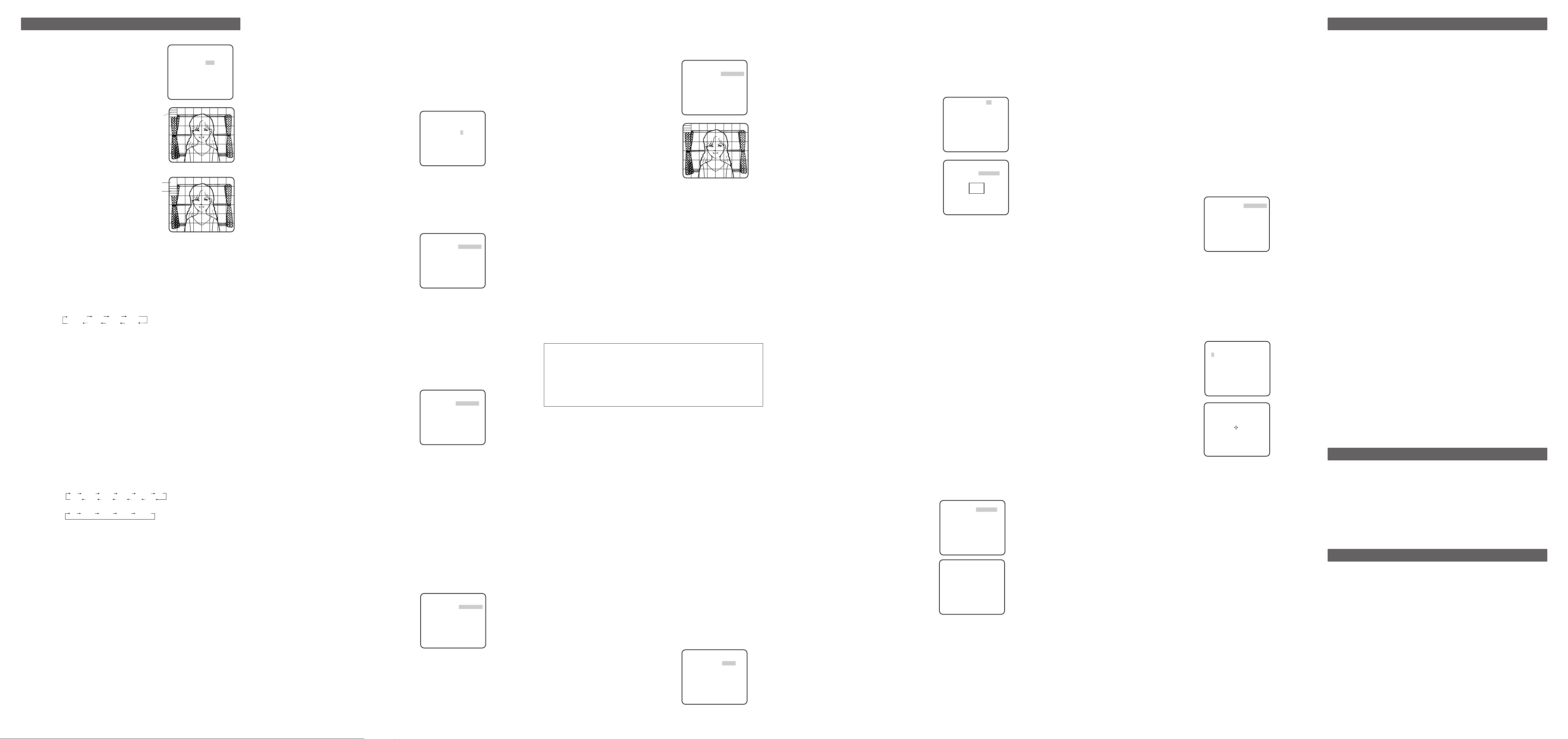
8. Motion Detection Setting (MOTION DET)
When a series of changes in pictures is detected, the camera outputs an alarm to the external device such as a disk recorder. The recorder will start recording the pictures.
1. Select a mode for MOTION DET on the CAMERA SETUP menu.
The default setting is OFF.
OFF: Disables the alarm output.
MODE1↓: Outputs alarm when a series of
motions is detected.
MODE2: Outputs alarm when a series of
scene changes is detected.
→ The MODE 1 menu opens when you
select MODE1 and press SET .
2. Adjust for LEVEL to optimize the sensitivity of
detection.
3. Select a dwell time. The default is 2S.
Available time (second): 2, 5, 10, 30
The next detection will be performed after
the set time elapses.
4. Select MASK SET and press SET.
→ A 48-split screen opens.
• Specify non-detection (mask) and detection
areas in the same way as described earlier
in 2-2 ELC Mode.
•Hold down SET for 2 seconds to return to the MOTION DET menu.
Note: Perform the setting of mask area after STABILIZER in the CAMERA SETUP menu is
set to OFF.
5. Select ON or OFF for ALARM under DISPLAY MODE.
ON: Blinks the respective areas in the DISPLAY MODE screen if a motion is detected.
OFF: Does not indicate motion detection in the DISPLAY MODE screen. This is applica-
ble when WV-RM70, WV-CU550 series, WV-CU161 or WV-CU360 controller is used.
6. Select DISPLAY MODE and press SET to see the current settings.
When a motion is detected, the area will blink.
•Press SET to return to the MODE1 menu.
7. As necessary, repeat to perform LEVEL adjustment and MASK setting by checking on the
DISPLAY MODE screen.
Notes:
• In systems other than Panasonic, select OFF for MOTION DET to prevent system
devices from confusing time-code signal with alarm signal.
• Set MASK SET over the areas where leaves or curtains etc. are swaying.
• Adjust the detection level to prevent detection from confusing motion with noise under
low light conditions.
• It takes about 0.2 seconds for the alarm signal to reach the VTR’s alarm terminal after
detection.
• The motion/scene change detection is not specifically intended to prevent theft or fire.
9. Digital Noise Reduction Setting (DNR)
Select a DNR mode suitable to the camera site conditions. The default setting is HIGH.
HIGH: Greatly reduces noise, though it produces afterimages when objects move.
LOW: Slightly reduces noise, and produces less afterimages.
10. Resolution Setting (RESOLUTION)
Select a horizontal resolution mode. The default setting is HIGH.
NORMAL: Resolves more than 480 TV lines.
HIGH: Resolves typically 540 TV lines, though noise may increase when SENS UP is acti-
vated in low lighting conditions.
11. Black and White Mode Setting (BW MODE)
1. Select BW MODE on the CAMERA SETUP menu and press SET.
→ The BW MODE menu opens.
2. Select a mode for BW. The default setting is OFF.
AUTO1: Sets the mode to black-and-white if the picture is dark or to colour if the picture
is bright enough.
AUTO2: Functions the same as AUTO1, except this is applied to the use of a light source
from a halogen lamp (wavelength ≥ 800nm).
EXT: Sets the mode to black-and-white if the sensor connected to the DAY/NIGHT IN ter-
minal is activated.
ON: Sets the mode to black-and-white.
OFF: Sets the mode to colour.
Notes:
• There may be cases where AUTO1 or AUTO2 does not function well if the camera is
aimed at subjects continuously moving or a scene filled with a single colour such as a
blue sky.
• It is possible to set up the back-focus mode to compensate for defocus liable to happen when the camera automatically switches between the colour and black-and-white
modes. Refer to "16. Back-focus Setting" for details.
→ When AUTO1 or AUTO2 is selected, LEVEL and DURATION TIME appear.
3. Select a threshold LEVEL to switch between
the colour and black-and-white mode. The
default setting is HIGH.
HIGH: Switches the mode at around 5 lux
illumination.
LOW: Switches the mode at around 1 lux
illumination.
4. Select a duration time to determine whether
to switch the mode. The default setting is 30
seconds.
Available time: (Short) 10 s ↔ 30 s ↔ 60 s ↔ 300 s (Long)
About MODE2 of Motion Detection
• The camera will detect a scene change in the following cases.
When the lens is fully sprayed or covered with a cloth, lid, or the like
When the camera direction is suddenly changed
• The camera will not detect a scene change in the following cases.
When a cloth with patterns covers the lens and it sways in the wind
When some portions in the screen are not veiled
When the screens are similar in scene patterns although the camera direction has changed
• The camera will faultily detect a scene change in the following cases.
When an obvious brightness change arises (ex. On/Off of the lamps)
When objects move continuously such as traffic in busy streets
5. Select a burst signal mode. The default setting is ON.
ON: Supplies the (colour) burst signal with black-and-white composite video.
OFF: Supplies no burst signal.
Note: Using ON is usually recommended. Try both ON and OFF to match to connected
devices (recorders, monitors, etc.) that have different characteristics.
12. Privacy Zone Setting (PRIVACY ZONE)
Perform settings of up to eight privacy zones where you wish to veil the monitor screen.
1. Select ON(1), ON(2) or OFF for PRIVACY ZONE on page 2 of the CAMERA SETUP menu
and press SET. The default setting is OFF.
ON (1)↓: Veils the zone with grey.
ON (2)↓: Veils the zone with mosaic.
OFF: Displays pictures normally.
→ The ZONE NUMBER selection menu
opens.
2. Select a zone number on the top line using
L/R buttons and press SET. The zone number followed by an asterisk * indicates that it
has been already registered.
→ POSITION, SCALE, and a frame appear
on the menu.
3. Select
→PUSH SW for POSITION and press
SET.
→ Position selection becomes available.
4. Move the picture portion to be veiled to the
centre of the frame using the L/R/U/D buttons.
5. Select
→PUSH SW for SCALE and press SET.
→ Zone scale adjustment becomes available.
6. Adjust the zone scale using the L/R/U/D buttons.
7. To apply the settings, move the cursor to SET and press SET.
→ The screen returns to the ZONE NUMBER selection menu.
To delete the settings, select DEL and press SET.
13. Mirror Setting (MIRROR)
Specify whether to horizontally reverse the camera picture. The default setting is OFF.
OFF: Displays pictures normally.
ON: Displays pictures horizontally reversed.
14. Lens Drive Signal Selection (LENS-DRIVE)
Select the suitable drive type for the auto iris lens mounted. The default setting is DC.
DC: Is used for DC drive type lens.
VIDEO: Is used for video drive type lens.
15. Auto Image Stabilizer (STABILIZER)
This function electronically compensates for an unstable camera image due to movement of
a mounting pole or bracket. The default setting is OFF.
ON: Automatically compensates for an unstable image.
OFF: Image stabilizer will not operate.
Notes:
•When set to ON, some effective pixels on the edge of the CCD are used by the stabilization function. This may result in a small reduction in resolution and a narrower
angle of view. After activating the image stabilizer function, check that the field of view
is correct.
•Image stabilization may not function where there is excessive camera movement or
when the scene is low light or low contrast objects.
16. Back-focus Setting (BACK-FOCUS SETUP)
If applicable, perform adjustment of the lens focus as described in "Before Back-focus
Adjustment" on the INSTALLATION page. Perform adjustment of the back focus (flangeback: the gap between the lens and focal plane) remotely on this menu using a system controller. After installation, you can perform this adjustment when defocus arises that may be
caused by long-term use, environmental changes, etc.
1. Select BACK-FOCUS on the WV-CP480 TOP
menu and press SET.
→ The BACK-FOCUS SETUP menu opens.
2. Select ABF and press SET.
→ Adjustment is automatically performed.
Notes:
• Performing ABF will function to obtain the
best focus around the centre areas in a
scene.
• Performing ABF is available only when
OFF, X2 AUTO, or X2 FIX is selected for
SENS UP.
3. Select MANUAL-ADJ and press SET if manual adjustment is required.
The manual back-focus adjustment screen
will open.
•Use the L/R buttons to move the "I" cursor
and obtain a proper focus.
→ Refer to the 4-digit number on the second bottom line. The larger the number is, the
better the focus will be.
• Select RET and press SET to go back to the menu setup.
4. Select a mode for C/L
←→ B/W. The default setting is AUTO.
AUTO: Adjusts the back-focus automatically every time the camera switches the mode
between colour and black-and-white. AUTO is usable only when OFF, X2 AUTO, or X2
FIX is selected for SENS UP.
PRESET: Adjusts the back-focus to the positions for colour mode and black-and-white
mode that are preset by performing step 2 (automatic) or step 3 (manual) under the
respective light conditions.
FIX: Fixes the back-focus after adjustment.
6. Synchronization Setting (SYNC)
1. Select a sync mode.
VD2: Multiplexed vertical drive, highest priority
LL: Line-Lock, follows the phase of supplied AC power, 2nd priority
EXT (VBS): Composite colour video or black-burst sync, 3rd priority
EXT (VS): Composite monochrome video or composite HV sync, 4th priority
INT: Internal sync, lowest priority
Note: Selection is not available when VD2 is added to the camera. Selection from LL and
VBS/VS is available when the respective sync is added.
2. Line-Lock Vertical Phase Adjustment (V PHASE)
• Select LL and press SET.
• Prepare a dual-trace oscilloscope and supply it with the video output of the camera to be
adjusted and that of the reference camera.
• Set the oscilloscope to the vertical rate and
expand the V-sync portion.
• Select a proper COARSE phase from 16
steps (22.5 degrees/step) that makes the
two video signals on the oscilloscope the
closest.
• Select a proper FINE phase so that the two
video signals on the oscilloscope come as
close as possible.
Notes:
•Moving the "I" cursor across the +/- end
will shift the FINE range.
• Press L and R simultaneously to reset the V PHASE to the default (0 degree).
• Keep pressing L or R for a second to move the "I" cursor faster if necessary.
• Spike noise if contained in the AC mains may disturb synchronization of LL.
3. VBS Phase Adjustment (H PHASE/ SC)
• Select INT for SYNC and press SET.
• Supply a VBS (Composite colour video or black-burst) signal to the GEN-LOCK IN terminal.
→ INT will change to EXT (VBS).
•Select EXT (VBS) and press SET.
→ A sub menu displaying H PHASE and SC
(Sub carrier) opens.
<H PHASE Adjustment>
• Prepare a dual-trace oscilloscope and
supply it the video output of the camera
to be adjusted and the VBS.
• Set the oscilloscope to the horizontal rate
and expand the H-sync portion.
•Move the "I" cursor so that phase of the VBS and that of the camera match on the
oscilloscope.
Adjustable range: From zero to – 2.0 microseconds
<SC (Sub-carrier) Phase Adjustment>
•Connect the camera to a special effect generator (SEG) and supply the output of the
SEG to a monitor.
• Select a proper COARSE phase from 4 steps (90 degrees/step) while observing the
original scene and the scene on the monitor to make these colours similar.
• Select a proper FINE phase so that these colours match as closely as possible.
• For more accurate adjustment, prepare a vectorscope and supply it with the camera
signal to be adjusted and the output of the SEG as a reference signal. Adjust SC to
match on the vectorscope.
4. VS Phase Adjustment (H PHASE)
• Supply a VS (Composite monochrome video
or composite HV) signal to the GEN-LOCK
IN terminal.
•Adjust the H phase referring to
<H PHASE Adjustment> described above.
7. White Balance Setting (WHITE BAL)
Select a mode for WHITE BAL on the CAMERA SETUP menu. The default is ATW1.
ATW1: Is automatically adaptable to the colour temperatures of 2 700K - 6 000K.
ATW2: Is automatically adaptable to the use of sodium lamps (2 000K - 6 000K).
AWC: Is automatically adaptable to the colour temperatures of 2 000K -10 000K.
Notes:
•When ATW1 or ATW2 is selected, no further operation is required.
• ATW1 and ATW2 do not appear on the setup menu of the system controller.
• Select AWC in the following cases: the colour temperature is out of the 2 000K 6000K range, the scene contains mostly high colour temperatures such as blue sky or
sunset, or the scene is dim.
AWC Setting
1. Select AWC and press L.
→ AWC will change to AWC → PUSH SW.
2. Press SET.
→ PUSH SW will be highlighted while the AWC setting is performed.
Note: If the white balance is not set, PUSH SW is being highlighted.
3. Press R.
Manual Fine Adjustment
Perform fine adjustment as necessary.
1. Select WHITE BAL and press SET.
→ Fine adjustment menu of ATW or AWC will
open.
2. Adjust finely R (Red) and B (Blue) gain by
moving the "I" cursor.
2-2. ALC Mode with SUPER-D3 OFF and ELC Mode
1. Select ELC for ALC/ELC on the CAMERA
SETUP menu or select OFF for SUPER-D3
on the ALC CONT menu.
→ MASK SET↓ appears on each of the ELC
CONT and ALC CONT menu.
2. Select MASK SET and press SET.
→ The 48 mask areas appear overlaid on
the camera picture with the blinking cursor in the upper left corner.
3. Move the cursor to an area where the backlight is bright and press SET to mask the
area.
→ The masked area appears alternately
white and blinking when the cursor is on
the area, or it turns white when the cursor
is on other areas.
4. To cancel masking, move the cursor to a
masked area and press SET.
→ When masking of the area is cancelled, it
changes from white to normal.
To cancel all the masking, press L and R
simultaneously for 2 seconds.
5. Repeat step 3 and 4 as necessary.
6. Press SET for 2 seconds or more.
→ The ALC CONT menu appears.
7. Adjust the video output level (LEVEL) by
moving "I" cursor.
Note: If ON is selected for SUPER-D3, a shadow (black line) may appear at the boundary
between the bright and the dim portions. This is a natural phenomenon and does not
indicate trouble.
3. Shutter Speed Setting (SHUTTER)
Select a proper shutter speed when ALC is selected on the CAMERA SETUP menu.
Selecting a faster speed will reduce blurring when objects quickly move. The default setting
is OFF.
Notes:
• This setting is not available when SUPER D3 is set to ON.
•When a faster speed is selected for the electronic shutter, the picture will generally
become darker, and sometimes a smear (vertical stripes caused by bright objects)
may appear.
4. Gain Control Setting (AGC)
Select an automatic gain control mode. This setting raises the gain and brightens the image
under low light conditions. The default setting is ON (HIGH).
Available modes: ON (HIGH / high), ON (MID / medium), ON (LOW / low), OFF
5. Electronic Sensitivity Enhancement (SENS UP)
Select a proper enhancement rate when the camera is set to ALC mode. The higher rate you
select, the brighter the picture will be. The default setting is OFF.
AUTO: Sets AGC to ON and adaptively raises the sensitivity up to the selected amplifica-
tion rate, for example 10 times when set to X10 AUTO.
FIX: Raises the sensitivity fixedly to the selected rate.
OFF: Does not raise the sensitivity.
Notes:
• Only AUTO is available when the ELC/ALC mode is set to ELC.
• There may be cases where some types of system controllers cannot operate some of
the SENS UP functions. If this happens, use the direction buttons on the camera.
•When you select AUTO for SENS UP and ON for SUPER-D3, the SENS UP function
has priority so that the SUPER-D3 function is not activated automatically.
•While the SENS UP function is selected, noise, spots or a whitish phenomenon may
appear in the picture when the sensitivity of the camera is increased. This is a normal
phenomenon.
•Only when OFF, X2 FIX, or X2 AUTO is selected for sensitivity enhancement (SENS
UP), it is possible to perform ABF adjustment or to select AUTO for C/L
→ B/W on the
BACK-FOCUS SETUP menu. When a sensitivity rate other than X2 FIX or X2 AUTO is
selected, use PRESET and FIX for C/L
→ B/W on the BACK-FOCUS SETUP menu.
SETTING PROCEDURES
Blinking
Blinking
White
SUPER-D3 OFF:
OFF (1/50) 1/120
1/10000 1/4000 1/2000 1/1000
1/250 1/500
OFF
X2 AUTO
SUPER-D3 OFF:
SUPER-D3 ON:
X32 FIX X10 FIX X6 FIX X4 FIX X2 FIX
OFF
X2 AUTO
X4 AUTO X6 AUTO X10 AUTO
X16 FIX
X4 AUTO X6 AUTO X10 AUTO
**ALC CONT**
BACK LIGHT COMP
SUPER-D3 OFF
MASK SET
LEVEL ..I......
- +
RET TOP END
OFF
↵
**SYNC**
V PHASE
COARSE 1(1--16)
FINE ....I....
- +
RET TOP END
**SYNC**
H PHASE ........I
- +
SC COARSE 1(1--4)
SC FINE .I.......
- +
RET TOP END
**SYNC**
H PHASE ........I
- +
RET TOP END
**ATW1**
R ....I....
- +
B ....I....
- +
RET TOP END
** MODE1 **
LEVEL ........I
- +
DWELL TIME 2S
DISPLAY MODE
ALARM OFF
MASK SET
RET TOP END
↵
↵
**BW MODE**
BW AUTO1
LEVEL HIGH
DURATION TIME .I..
S L
BURST(BW) ON
RET TOP END
**ZONE NUMBER 1*/8**
RET TOP END
**ZONE NUMBER 1*/8**
POSITION
SCALE
SET DEL
RET TOP END
→
PUSH SW
→
PUSH SW
**BACK-FOCUS SETUP**
ABF
MANUAL-ADJ
← →
B/W AUTO
C/L
SETUP-SW LOCK OFF
NEAR FAR
.........I..........
INDICATOR 9999
RET TOP END
**MANUAL-ADJ**
NEAR FAR
.........I..........
INDICATOR 9999
RET TOP END
→
PUSH SW
↵
**SPECIAL SETUP**
CHROMA GAIN .....I...
AP GAIN ...I.....
PEDESTAL .....I...
– +
PIX OFF
COMMUNICATION COAX
CAMERA RESET
SER.NO. XXXXXXXX
RET TOP END
↵
→
PUSH SW
**PIX OFF**
1 2 3 4
5 6 7 8
9 10 11 12
13 14 15 16
000 000
RET TOP END
 Loading...