

Panasonic WV-CP480 Operating Instructions
Color CCTV Camera
Operating Instructions
WV-CP480
Model Nos.
WV-CP484
Before attempting to connect or operate this product,
please read these instructions carefully and save this manual for future use.
N1104-4075 3TR003296EAA Printed in Japan
Power disconnection. Unit with
or without ON-OFF switches
have power supplied to the unit
whenever the power cord is
inserted into the power source;
however, the unit is operational
only when the ON-OFF switch
is in the ON position. The
power cord is the main power
disconnect for all units.
The lightning flash with arrowhead symbol, within an equilateral triangle, is intended to
alert the user to the presence
of uninsulated "dangerous voltage" within the product's enclosure that may be of sufficient
magnitude to constitute a risk
of electric shock to persons.
The serial number of this product may be found
on the surface of the unit.
You should note the serial number of this unit
in the space provided and retain this instruction
as a permanent record of your purchase to aid
identification in the event of theft.
Model No.
Serial No.
SA 1966
SA 1965
(Lens: Option)
WARNING: To prevent fire or electric shock hazard, do not expose this appliance to rain or moisture.
The apparatus shall not be exposed to dripping or splashing and that no objects filled with liquids, such as vases, shall be placed on the apparatus.
CAUTION: TO REDUCE THE RISK OF ELECTRIC SHOCK,
DO NOT REMOVE COVER (OR BACK).
NO USER-SERVICEABLE PARTS INSIDE. REFER SER-
VICING TO QUALIFIED SERVICE PERSONNEL.
CAUTION
RISK OF ELECTRIC
SHOCK DO NOT OPEN
NOTE: This equipment has been tested and
found to comply with the limits for a Class A
digital device, pursuant to Part 15 of the FCC
Rules. These limits are designed to provide
reasonable protection against harmful interference when the equipment is operated in a
commercial environment. This equipment generates, uses, and can radiate radio frequency
energy and, if not installed and used in accordance with the instruction manual, may cause
harmful interference to radio communications.
Operation of this equipment in a residential
area is likely to cause harmful interference in
which case the user will be required to correct
the interference at his own expense.
FCC Caution: To assure continued compliance, (example - use only shielded interface
cables when connecting to computer or
peripheral devices). Any changes or modifications not expressly approved by the party
responsible for compliance could void the
user’s authority to operate this equipment.
For U.S.A
Caution:
Before attempting to operate this product, please
read the label on the surface of the unit.
The exclamation point within
an equilateral triangle is intended to alert the user to the presence of important operating
and maintenance (servicing)
instructions in the literature
accompanying the appliance.
This Class A digital apparatus complies with
Canadian ICES-003.
LIMITATION OF LIABILITY
IN NO EVENT SHALL MATSUSHITA ELECTRIC INDUSTRIAL CO., LTD. BE LIABLE TO ANY
PARTY OR ANY PERSON, EXCEPT FOR REPLACEMENT OR REASONABLE MAINTENANCE
OF THE PRODUCT, FOR THE CASES, INCLUDING BUT NOT LIMITED TO BELOW:
(1) ANY DAMAGE AND LOSS, INCLUDING WITHOUT LIMITATION, DIRECT OR INDIRECT,
SPECIAL, CONSEQUENTIAL OR EXEMPLARY, ARISING OUT OF OR RELATING TO THE
PRODUCT;
(2) PERSONAL INJURY OR ANY DAMAGE CAUSED BY INAPPROPRIATE USE OR NEGLI-
GENT OPERATION OF THE USER;
(3) UNAUTHORIZED DISASSEMBLY, REPAIR OR MODIFICATION OF THE PRODUCT BY
THE USER;
(4) INCONVENIENCE OR ANY LOSS ARISING WHEN IMAGES ARE NOT DISPLAYED, DUE
TO ANY REASON OR CAUSE INCLUDING ANY FAILURE OR PROBLEM OF THE PRODUCT;
(5) ANY PROBLEM, CONSEQUENTIAL INCONVENIENCE, OR LOSS OR DAMAGE, ARISING
OUT OF THE SYSTEM COMBINED BY THE DEVICES OF A THIRD PARTY;
(6) ANY CLAIM OR ACTION FOR DAMAGES, BROUGHT BY ANY PERSON OR ORGANIZA-
TION BEING PHOTOGENIC SUBJECT, DUE TO VIOLATION OF PRIVACY WITH THE
RESULT OF THAT SURVEILLANCE-CAMERA’S PICTURE, INCLUDING SAVED DATA,
FOR SOME REASON, THAT BECOMES PUBLIC OR IS USED FOR THE PURPOSE
OTHER THAN SURVEILLANCE;
WV-CP480
WV-CP484

• Auto-Back-Focus (flange back adjustment):
1-push adjustment (local/remote), manual adjustment (local/remote), automatic
adjustment at BW/CL transition
• Light control: ALC (DC/Video), ELC
• Terminals: Alarm output, Day/night sensor input
• Miscellaneous: Privacy zone setting,
Video motion detection, etc.
FEATURES
MAJOR OPERATING CONTROLS AND THEIR FUNCTIONS
q AC Inlet (120 V AC 60 Hz)
<WV-CP480 only>
Is connected by the supplied power
cord.
q Power Input Terminal (DC 12 V IN, AC
24 V IN, GND) <WV-CP484 only>
Receives 24 V AC or 12 V DC from the
power supply.
w Gen-lock Input Connector
(GEN-LOCK)
Receives sync source signal from an
external device.
e Video Output Connector
(VIDEO OUT)
Supplies the video output to the system
devices.
r Power Indicator (POWER)
Is lit when the power is supplied.
t Alarm Output Terminal
(ALARM OUT/GND)
Supplies the alarm output signal to the
alarm input connector of an external
device when the camera detects motion.
(Open collector output: 16 V DC,
100 mA max).
y Day/Night Input Terminal (DAY/NIGHT
IN/GND)
Is connected to an external sensor to
receive day/night detection signals.
u Camera Mounting Adapter
Is used to mount the camera onto a
bracket.
i Auto Iris Lens Connector
Is connected by the auto iris lens connector (4-pin male).
o Gen-lock Termination Switch
(HI-Z G/L 75Ω)
Is used to terminate the line with a 75 Ω
when the camera is at the line end.
!0 Set Button ((SET) ABF/MENU)
Adjusts the back focus by pressing this
button while displaying camera pictures
(ABF: Automatic Back Focus). Refer to
ABOUT SETUP MENUS for setup operations.
!1 Direction Buttons ((LEFT) NEAR,
(RIGHT) FAR, (UP), (DOWN))
In the back-focus adjustment, the LEFT
and RIGHT buttons are used for manual
adjustment. Refer to ABOUT SETUP
MENUS for setup operations.
The side panel is provided for the WV-CP480 only.
Slide the panel to the left until it locks.
Panasonic’s WV-CP480 series cameras introduce a new level of high picture quality by use
of Super-Dynamic 1/3 inch CCD and digital signal processing LSIs.
• Super Dynamic: 128x with zone-free
brightness detection
• High sensitivity: 0.08 lx in B/W mode,
0.6 lx in color mode (F1.4 Sens-up OFF)
• High resolution: 540 TV lines typical, 520
TV lines minimum
• Sensitivity enhancement: Up to 10x
AUTO/32x FIX
• Synchronization:
VD2/ LINE-LOCK/VBS/VS/INTERNAL
1. Do not attempt to disassemble the camera.
To prevent electric shock, do not remove screws or covers.
There are no user-serviceable parts inside. Ask qualified service personnel for servicing.
2. Handle the camera with care.
Do not abuse the camera. Avoid striking, shaking, etc. The camera could be damaged
by improper handling or storage.
3. The installation should be made by qualified service personnel or system installers.
4. Do not use strong or abrasive detergents when cleaning the camera body.
Use a dry cloth to clean the camera when dirty. When the dirt is hard to remove, use a
mild detergent and wipe gently. Then wipe off the remaining detergent with a dry cloth.
5. Clean the CCD faceplate with care.
Do not clean the CCD with strong or abrasive detergents. Use lens tissue or a cotton
tipped applicator and ethanol.
6. Never face the camera towards the sun.
Do not aim the camera at bright objects. Whether the camera is in use or not, never aim
it at the sun or other extremely bright objects. Otherwise, blooming or smears may be
caused.
7. Do not operate the camera beyond the specified temperature, humidity or power
source ratings.
Use the camera at temperatures within –10 °C to +50 °C {14 °F - 122 °F}, and humidity
below 90 %. The input power source is 120 V AC 60 Hz for WV-CP480 and 24 V AC
60 Hz/12 V DC for WV-CP484.
8. Avoid connections during a lightning storm.
Otherwise, an electric shock may be caused.
PRECAUTIONS
Protection screw for
transportation
<WV-CP480>
120VAC 60Hz
q
ew
GEN-LOCK VIDEO OUT
POWER
GND
ALARM
OUT
GND
DAY/
NIGHT
IN
r
t
u
y
i
<WV-CP484>
!0 !1
POWER
t
e
w
y
VIDEO OUT
NEAR
(LEFT) (RIGHT)
GEN-LOCK
Hi-Z
G /L75Ω
ABF/MENU
(SET)
1 - 2 - DC12V IN
1 - 2 - AC24V IN
(UP)
(DOWN)
r
FAR
GND
q
u
o
Hi-Z
(UP)
G /L75Ω
FAR
ABF/MENU
NEAR
(RIGHT)
(SET)
(LEFT)
(DOWN)
o!0 !1
■ Connections
Notes:
• Before connecting the power cables, be sure to remove the protection screw for transportation. Otherwise, the camera can be damaged.
• Firmly connect the power cord.
• When the camera is mounted on a pan/tilt table, the power cord should be long enough.
Otherwise, it may be unplugged from the camera.
• Connection of 120 V AC 60 Hz to WV-CP480
Plug the supplied power cord to the AC inlet of the
camera.
• Connection of 12 V DC/24 V AC 60 Hz to WV-CP484
12 V DC
Use the formula below to calculate the power cable and power supply. The voltage sup-
plied to the power terminals of the camera should be within 10.8 V DC and 16 V DC.
10.8 V DC ≤ V
A
− 2(R x I x L) ≤ 16 V DC
L : Cable length (m)
R : Resistance of copper wire (Ω/m)
V
A : DC output voltage of power supply unit
I : DC current consumption (A). See specifications.
Resistance of copper wire [at 20 °C {68 °F}]
24 V AC
The recommended cable length and thickness are shown in
the table for reference. The voltage supplied to the power
terminals of the camera should be within 19.5 V AC and
28 V AC.
• Video Cable Connections
GEN-LOCK Input
Connect an external sync source to the
GEN-LOCK input connector. When looping through, use a branch connector
(not supplied). Set the termination switch
to 75 Ω when the camera is at the line
end, or set it to HI-Z in other cases.
VIDEO OUT
Connect the video output connector to the monitor or other system device with the procured coaxial cable. The maximum extensible length is shown in the table.
• External Terminal Connections
ALARM OUT
Connect an external device such as a buzzer, recorder, etc.
Specifications are: open collector output: 16 V DC, 100 mA max.
OFF: High, inactive
ON: Low, active
DAY/NIGHT IN
Connect an external device such as an
optical sensor.
Specifications are: pulled-up input: 5 V DC,
2 mA min.
OFF: Open contact, inactive
ON: Closed contact, active
Notes:
• To validate the sensor inputs, select
EXT for BW on the BW MODE menu.
• Use a relay unit if the voltage or current
of the connected device exceeds the ratings.
Cautions:
1. The installation should be made by qualified service personnel or system installers.
2. The connections should comply with the National Electrical Code (NEC 725-51).
3. ONLY CONNECT THIS TO A 24 V AC CLASS 2 POWER SUPPLY. Be sure to connect
the grounding lead to the GND terminal. (for WV-CP484)
4. To prevent fire or electric shock hazard, use a UL listed cable (VW-1, style 1007) for
the Input Terminal. (for WV-CP484)
5. Do not use a transformer larger than 10 VA. (for WV-CP484)
INSTALLATION
Copper wire
size (AWG)
Resistance
Ω/m
Resistance
Ω/ft
#24
(0.22 mm
2
)
0.078
0.026
#22
(0.33 mm2)
0.050
0.017
#20
(0.52 mm2)
0.03
0.010
#18
(0.83 mm2)
0.018
0.006
Copper wire
size (AWG)
Length (m)
Length (ft)
#24
(0.22 mm
2
)
20
65
#22
(0.33 mm2)
30
100
#20
(0.52 mm2)
45
160
#18
(0.83 mm2)
75
260
Type of coaxial cable
Recommended
maximum
cable length
RG-59/U
(3C-2V)
250
825
RG-6/U
(5C-2V)
500
1 650
RG-11/U
(7C-2V)
600
1 980
RG-15/U
(10C-2V)
800
2 640
(m)
(ft)
Optical sensor
Recorder,
Buzzer, etc.
DAY/
NIGHT
ALARM
IN
GND
OUT
GND
9 - 10 mm {3/8"}
Recommended Wire
AWG 22 - 28, single or stranded wire
120 V AC
60 Hz
120 V AC 60Hz
GEN-LOCK VIDEO OUT
ALARM
DAY/
NIGHT
GND
OUT
GND
POWER
IN
120 V AC 60Hz
GEN-LOCK VIDEO OUT
ALARM
DAY/
NIGHT
POWER
GND
OUT
GND
IN
BNC
BNC
12 V DC
24 V AC
BNC
BNC
- DC 12V IN
- AC 24V IN
12
+
–
- DC 12V IN
- AC 24V IN
12
From
Sync Source
(VBS/VS)
To Video IN
(CAMERA IN)
GND
GND
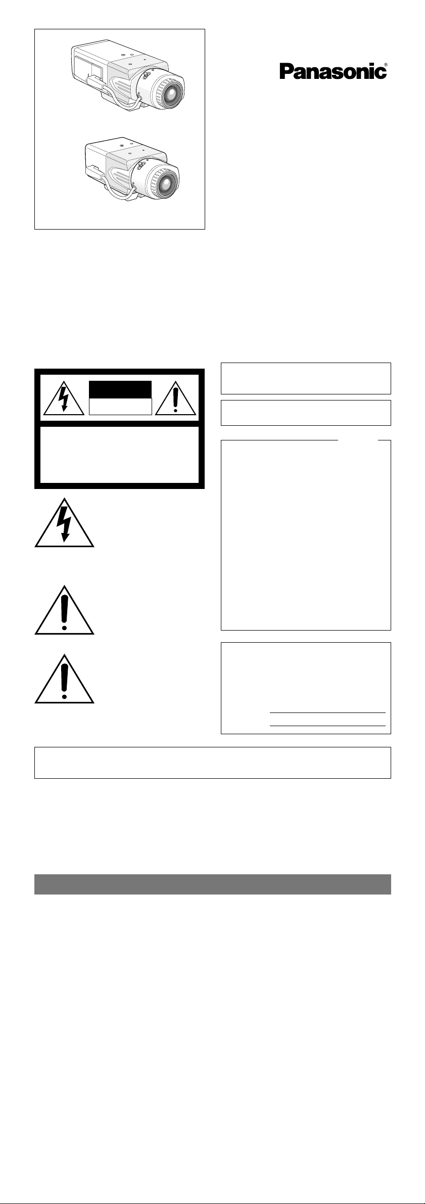
Caution for Mounting the Lens
Follow the directions shown in the figure for the
protrusion between a lens and the camera
body. This camera has a mount for use with the
CS-mount lens shipped from the factory.
A lens less than 450 g {0.99 lbs} can be mounted on the camera. If the lens is heavier, both
the lens and camera should be secured by the
supporter.
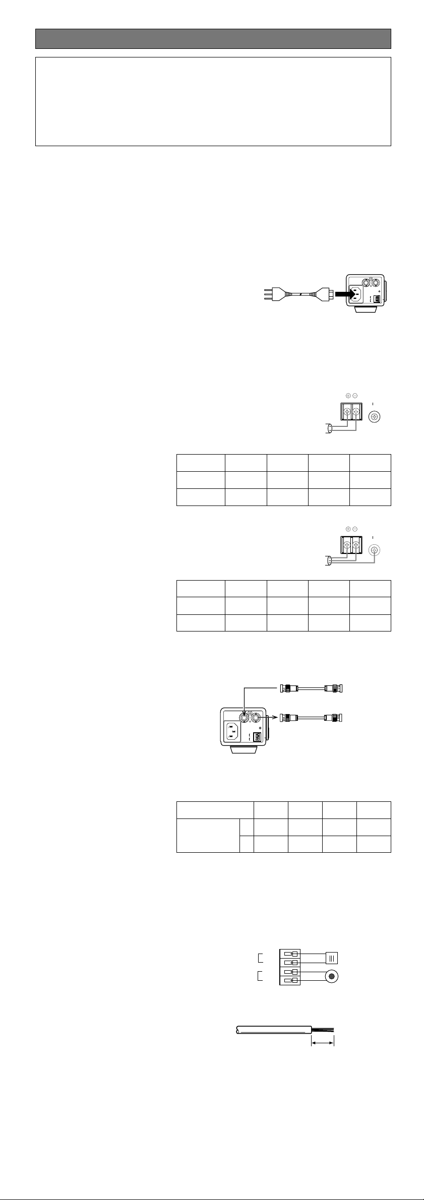
Mounting the Lens
1. Mount the lens.
2. Connect the lens cable to the auto iris connector on the side of the camera.
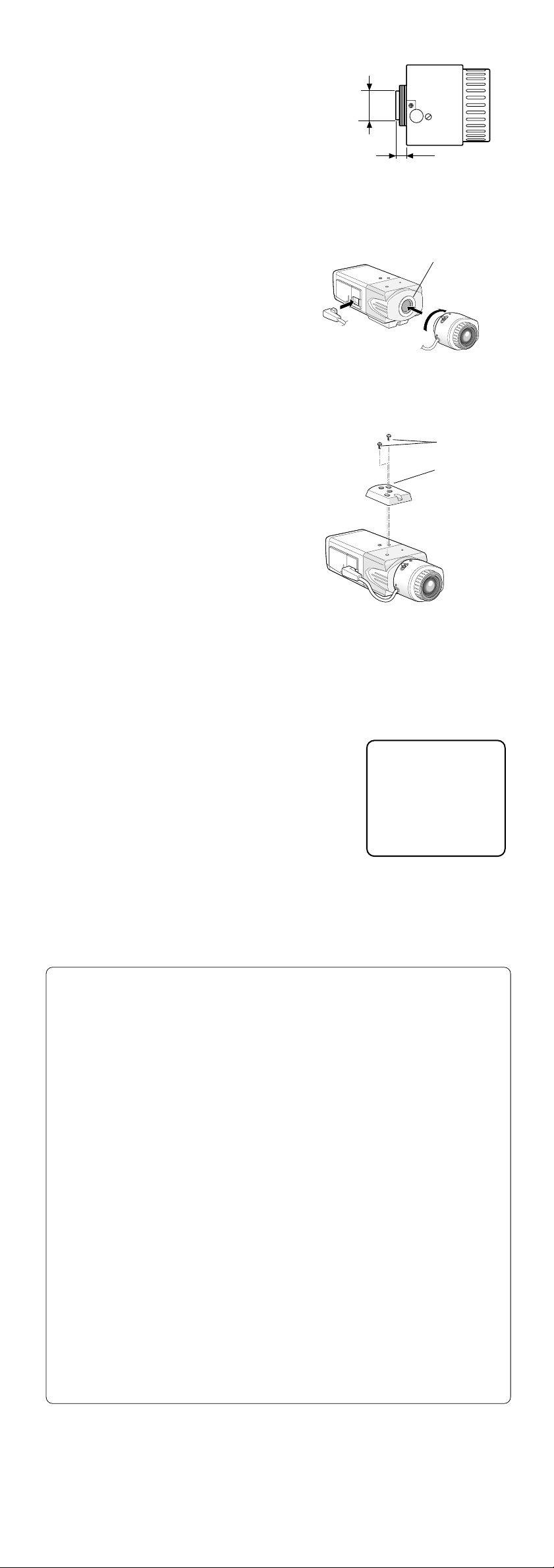
Mounting the Camera
• Mounting from the Top
Remove the mount adapter from the bottom
of the camera by removing the two fixing
screws. Attach the mount adapter to the top
as shown in the figure, then mount the camera on the mounting bracket.
Caution:
Be sure to use two original fixing screws for
the mount adapter.
Longer screws may damage the inner components. Or shorter screws may cause the
camera to fall down.
Flange-back (Back-focus) Adjustment
Before adjustment, read the Hints column below.
This adjustment is available only if SETUP-SW LOCK is set to OFF in the BACK-FOCUS
SETUP menu.
1. Aim the camera at the targeting objects and if applicable adjust the zoom angle.
2. Press the SET button.
→ A bar graph with "I" cursor and INDICA-
TOR (4-digit number) will be overlaid on
the camera picture.
→ Back focus will be automatically adjust-
ed.
3. If needed, perform manual adjustment using
the L and R buttons to obtain the best focus
on the targeted object while observing the
picture. See INDICATOR for reference.
The bar graph will disappear if no operation is
performed for around 10 seconds.
This adjustment can be also performed on the setup menu.
Refer to 16. Back-focus Setting for details.
Important: Do not use the ABF function for continuous or repetitive purposes (ex. auto-
focus etc.). This function is to be used to correct defocus caused by switching between
color and black - and - white when/after installing the camera.
Fixing Screws
Mount Adapter
C-mount: Less than 13 mm {1/2"}
CS-mount: Less than 8 mm {5/16"}
Lens Mount
Not larger than ø20 mm
{ø13/16"}
Hints
Before Back-focus Adjustment
• Adjustment procedures vary depending on the lens. Refer to the instructions included with the lens.
• Reset the back-focus by pressing the L and R buttons simultaneously on the camera, and adjust the back-focus.
• Move the lens focus to the FAR-end when using a fixed-focal lens (lens focus
adjustable type), and adjust the back-focus.
For Adjusting the Focus
• It is recommended that you lower the lighting for the object to be as dim as possible when adjusting the focus with an auto iris lens. This will make the iris open and
will result in an accurate focus even though the lighting conditions vary. This may
be slightly different from the best focus point in a specific lighting condition.
• Compared with cases under visible lights, using near-infrared lights may somewhat
deviate the focus. It is recommended that you select AUTO or PRESET for C/L ← →
B/W in the BACK-FOCUS SETUP menu to obtain a proper focus for each of visible
and near-infrared lights.
For Using General Vari-focal Lenses
1. Aim at the objects 10 meters away or more to adjust the back-focus.
2. For 8x and 10x class lenses, set the zoom to the WIDE-end and the focus to the
FAR-end, and then adjust the back focus.
3. For 2x and 3x class lenses, set the zoom to the TELE-end and the focus to the FARend, and then adjust the back focus.
4. Aim the camera at the targeted objects to place them in the center then coarsely
adjust the zoom angle and the focus of the lens. Finally, perform adjustment of the
back-focus in either ways of using ABF (automatically) or MANUAL-ADJ (manually).
Note: There may be lenses having an extended range in lens focus adjustment, except
Panasonic lenses. When using such a lens, set the lens focus back appropriately
from the applicable end position in the above step 2 and 3 depending on the lens,
and then perform back-focus adjustment. The back-focus will not be properly
adjusted if the lens focus is positioned into the extended range.
NEAR FAR
.........I..........
INDICATOR 9999
 Loading...