

Page 1

Operating
Instructions
Color CCTV Camera
WV-CF20
Panasonic
iltrmjtline tu ronnwr nr npr-fit? prcouci. <eiO «.uiiisjlelt-lv.
A
Page 2
ENGLISH VERSION
CONTENTS
PREFACE ............................................................ 2
CONNECTION
....................................................
6
FEATURES ‘ 2
PRECAUTIONS ................................................... 2
MAJOR OPERATING CONTROLS AND
THEIR FUNCTIONS
INSTALLATON .................................................... 4
..........................................
CAUTION
3
A
CAUTION:
TO REDUCE THE RISK OF ELECTRIC SHOCK, DO
NOT REMOVE COVER lOR BACK). NO USERSERVICEABLE PARTS INSIDE.
REFER SERVICING TO QUALIFIED SERVICE
PERSONNEL.
The lightning flash with arrowhead
symbol, within an equilateral triangle,
is intended to alert the user to the
presence of uninsulated "dangerous
voltage” within the product's
A
SA 1965
SA 1966
enclosure that may be of sufficient
magnitude to constitute a risk of elec
tric shock to persons.
The exclamation point within an
equilateral triangle is intended to alert
the user to the presence of important
operating and maintenance (servicing)
instructions in the literature accompa
nying the appliance.
SYSTEM CONNECTION
ADJUSTMENT
OPERATION
SPECIFICATIONS STANDARD ACCESSORIES
MAJOR OPTIONAL ACCESSORIES
..................................................................................For U.S.A
Warning :
This equipment generates and uses radio frequency
energy and if not installed and used properly, l.e„ in
strict accordance with the instruction manual, may
cause harmful interference to radio communications. It
has been tested and found to comply with the limits
for a Class A computing device pursuant to Subpart J
of Part 15 of FCC Rules, which are designed to pro
vide reasonable protection against such interference
when operated in a commercial environment.
.......................................................................... For CANADA
This digital apparatus does not exceed the Class A
limits for radio noise emissions from digital apparatus
set out in the Radio Interference Regulations of the
Canadian Department of Communications.
The serial number of this product may be found on
the bottom cover of the unit.
You should note the serial number of this unit in the
space provided and retain this book as a permanent
record of your purchase to aid identification in the
event of theft.
Model No.
Serial No. .
....................................................
.......................................................
....................................
.............................................
.... .
......................
.................
WV-CF20
6
7
8
9
9
9
WARNING:
TO PREVENT FIRE OR SHOCK HAZARD, DO NOT EXPOSE THIS APPLIANCE TO RAIN OR MOISTURE.
-1 -
Page 3

PREFACE
The Panasonic's Color CCTV Camera, WV-CF20, is
designed as a decorative surveillance camera.
With the built-in microphone,'audio is available by
connection with the optional Camera Drive Unit, WV-
PS11A.
As the audio and the power are multiplexed on the
video signal, the connection with the optional Camera
FEATURES
• 1 / 3-inch interline transfer CCD image sensor with
330000 pixels.
• Built-in the Auto Gain Control (AGC) and Auto Trac
ing White Balance Control (ATW).
• A single coaxial cable for connection between the
camera and optional Camera Drive Unit,
• An optional white Dome Cover, WV-CF1WA, is
available.
PRECAUTIONS
Drive Unit can be made by using a single coaxial
cable.
The maxirrium cable length for the monitor connection
is 200m with 3C-2V coaxial cable or 500m with 5C-2V
coaxial cable.
• Built-in internal microphone.
• Easy mounting of the camera onto the Camera Fix
ing Angle.
• By using the Optional Ceiling Mount Bracket, WVOlOOA, or Wall Mount Bracket, WV-Q103A, surface
mount is available.
1, Do not attempt to disassemble the camera.
To prevent electric shock, do not remove screws or
cover.
There are no user-serviceable parts inside. Refer
servicing to qualified service personnel.
2, Handle this camera with care.
Do not abuse the camera. Avoid striking or shaking
it. The camera could be damaged by improper
handling or storage.
3, Do not expose the camera to rain or moisture and
avoid operation in wet areas.
Take immediate action if the camera should be
come wet.
Turn power off and request servicing to qualified
service personnel. Moisture can damage thg
camera and also create the danger of electric
shock.
4. Never aim the camera at the sun.
Whether the camera is in use or not, never aim it at
the sun or an extremely bright object as this could
cause smear.
5. Do not use the camera beyond its temperature,
humidity or power source ratings.
5-1 - Designed for indoor use.
Ambient temperature must not range beyond
-10°C - -F50'C,
5-2,Avoid using the camera when humidity is
above 90%.
-2-
Page 4
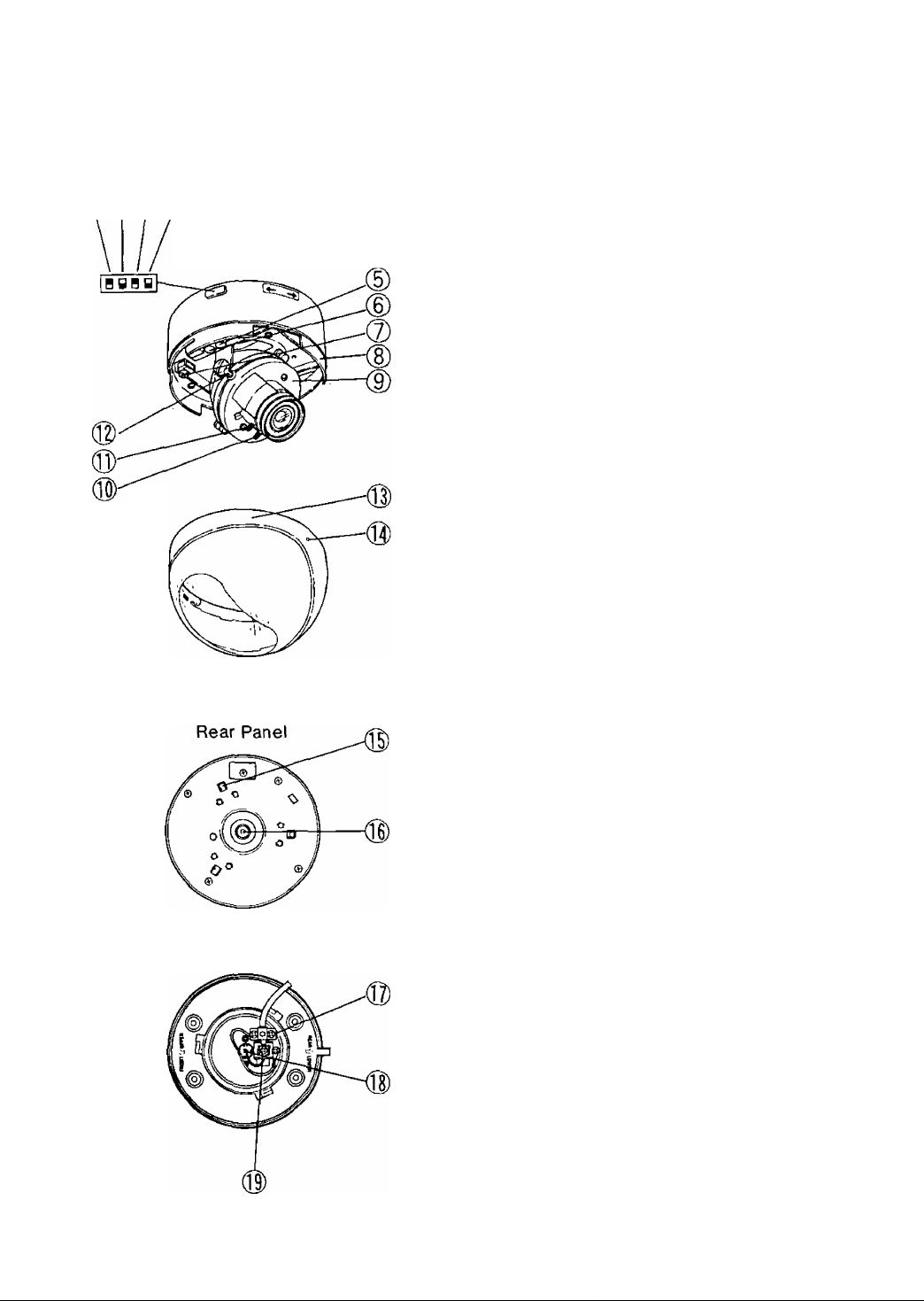
MAJOR OPERATING CONTROLS AND THEIR FUNCTIONS
1. AGC ON/OFF Switch (AGC ON/OFF)
This switch is used to select the gain of the video
®(|)(S)0
amplifier as follows.
ON : The lens iris is fully operated at low light
shooting, a clear picture is obtained by
automatic increase of the gain.
OFF : A natural and low-noise picture is obtained
under a low light condition.
Note : This switch is preset to the ON position at
the factory.
2. Back Light On/OH Switch (BLC ON/OFF)
When back light affects the picture, set this switch
to ON position for a clear picture. See page 4 for
more details.
3. Picture Detail Selection Switch
(PICTURE SHARP/SOFT)
This switch is used to select the sharpness of the
picture.
SHARP : The sharp picture is obtained,
SOFT : The soft picture is obtained.
Notes ; 1 .When connecting the WJ-450 Color Quad
Unit to this camera, set this switch to the
SOFT position.
2.This switch is preset to the SHARP
position at the factory.
Camera Fixing Angle
4. Microphone On/OH Switch
(MIC ON/OFF)
By setting this switch to the ON position, the audio
function can be obtained.
5. Audio Control (AUDIO, MAX/MIN)
The audio level can be adjusted by turning this
control.
This is preset to the MAX position at the factory.
6. Auto Light Control (ALC, H / L)
This control should be used only for shooting the
object in unusual lighting condition.
Do not adjust this control except the above condi
tion.
Note : To use this control, be sure to set the Back
Light On / Off Switch (2) to the OFF posi
tion,
7. Video Output Jack (VIDEO OUT)
This jack is used to adjust the angular field of view
or focus while observing the picture on the moni
tor.
-3-
Page 5

8. Panning Table
This is used to adjust the Right/Lett Angle of the
camera.
9. Camera Head
This is used to adjust the Up/Down Angle of the
camera,
10. Focus Ring
This is used to adjust the focus.
11. Zoom Ring
This is used to adjust the angle of view.
12. Lens Holders
These are used to adjust the picture tilt.
13. Dome Cover
This cover is used to protect the camera head.
14. Microphone Holes
15. Hooks
These are used to mount this unit to the Camera
Fixing Angle.
16. F-socket
This socket is connected with the F-plug (18) on
the Camera Fixing Angle.
17. Coaxial Cable Clamp
INSTALLATION
18. F-plug (Refer to the ADSUTMENT on Page 7 for
details)
This plug is used to connect with the F-socket (16)
on the camera head.
19. Video Output Terminal
This terminal is used to connect the coaxial cable
between the camera and the Camera Drive Unit
WV-PS11A , Colour Video Monitor WV-CM110A or
the equivalent,
BLC (Back Light Compensation) Description
When strong, unwanted background lighting inter
feres with the clarity of important scene objects, turn
the BLC On/Off Switch (2) to the ON position.
Cautions : 1. Setting the BLC On / Off Switch to the
“OFF" position is recommended when
using a pan/tilt head or if the sconce
object has rapid changes in illumina
tion, since the speed of lens iris becom
es slow in the "ON” position,
2. If the desired scene objects are not in
the center of the picture, back light
compensation may not work effectively.
-4-
Page 6

INSTALLATION
I. Mounting the Camera Fixing Angle
1-1. Make a hole (Dianneter 75mm) in the ceiling
board in the desired location.
'yyy/y/j
Mounting hole
1-2.After completing the cable preparation, fix the
coaxial cable to the Camera Fixing Angle.
1-3.Fix the Camera Fixing Angle onto the ceiling
board by using four Camera Fixing Angle
Mounting Screws,
Camera Fixing Angle
2. Mounting the camera onto the Camera Fixing
Angle (provided).
2'1 .Remove the Dome Cover (13) from the camera
by turning it counterclockwise.
Turn to counterclockwise
Dome Cover
2-2.Match “A" on the camera to "B" of the Camera
Fixing Angle and insert the camera into the
Camera Fixing Angle.
' ^ i Camera Fixing Angle
^ Mounting ScrewX4pcs
Note : 1. Match " 1} ’’ of the REAR LOWER /
FRONT UPPER to the desired position.
2.Use the optional Ceiling Mount Bracket
WV-QIOOA when the ceiling board cannot
support camera.
Important notice :
• The following installation should be made by qual
ified service personnel or system installers and
should conform to all local codes.
• Install to support the load of four times the total
weight.
2-3.Turn the camera toward the LOCK direction so
that “A" is brought to the center of "C".
2-4.Set the Fall Prevention Cap (provided) to pre
vent the camera body from falling as shown
below.
Remarks :
(1) lf the camera body is not installed correctly with
Camera Fixing Angle, the Fall Prevention Cap can
not be set,
(2) The camera body cannot be moved after the Fall
Prevention Cap has been set.
(3) Remove the camera body after the Fall Prevention
Cap has been removed.
-5-
Page 7

2-5.Adjust the camera angle to the desired posi
tion.
Refer to the Camera Angle Adjustment on
page 7 for details,
2-6. Match four grooves on the camera to four pro
jections of the Dome Cover,
Projections
grooves
CONNECTION
Preparation :
These connections should be made only by qualified
service personnel or system installers.
Cable Information
Coaxial Cable (Connection for the Video Output
Terminal (19) )
The maximum cable thickness for this camera is
5C-2V (RG-6/U) type.
2-7.Reattach the Dome Cover (13) to the camera
by turning this cover clociwise so that the “D"
position is in the front of the Camera Head.
Turn Counterclockwise
Dome Cover
Note : When assembling the coaxial cable/BNC con
nector, follow connector manufacture’s specific
directions.
SYSTEM CONNECTION
Connection with the optional Camera Drive Unit, WV-PS11A.
Connect a coaxial cable between the Video Output Terminal (19) on this camera and the Camera Input Connector
on the Camera Drive Unit, WV-PS11A.
Connection with the optional monitor WV-CM110A
Connect a coaxial cable between the Video Output Terminal (19) on this camera and the Camera Input Connector
on the monitor.
______
jO_ ^ i S> ® ® ® g> ^ (|^
Coaxial Cable (Option)
3C-2V (Maximum Cable length is 200m)
5C-2V (Maximum Cable length is 500m)
-6-
Video Monitor WV-CM110A
Page 8

ADJUSTMENT
1. Panning
The “E" line on the Panning Table can move be
tween the "F" and ‘'G" lines.
2. Tilting of the camera
Tilting angle is shown below.
4. Focusing
Precaution :The focus adjustment should be done
at the same time of the Camera Angle
Adjustment.
4-1 .Remove the Dome Cover (13) from the camera.
(Refer to item 2-1 of INSTALLATION on Page 5)
4-2.Loosen the Zoom Lock Lever.
4“3.Set the angular field of view according to the
scene desired.
4"4.After setting the angular field of view, tighten
the Zoom Lock Lever.
4"5.Loosen the Focus Lock Lever.
Note : The adjustment for picture tilt is normally re
quired. (refer to the item 3 of ADJUSTMENT
on page 7)
3. Picture Tilt
Loosen the two Lens Holders (12) and adjust the
picture tilt by turning the Camera Head (9).
4"6.Set the correct focus by turning the Focus Ring
(10).
4-7. After setting the correct focus, tighten the Focus
Lock Lever.
-7-
Page 9

5. Angular field of view and focus
By connecting the Video Output Jack (Diameter is
2.5mm) to the video input on a video monitor, local
adjustment of angular field of vie\w and/or focus is
available \while observing the picture.
Note : Be sure to use this jack only the purpose for
adjustment of the angular field of view or
focus.
Do not use this jack for anyother purpose.
Other wise the noise on the screen wilt be
obtained.
OPERATION
By using the optional Camera Drive Unit, WV-PS11A,
and Color Monitor, WV*CM1000, the sound from the
camera can be monitored.
Set the Michrophone On/Off Switch (4) to the ON
position.
On
B BBy
OFF
MIC
Note : When the distance between the camera
and speaker is too close, howling or
feedback may occur.
In this case, turn the Audio Control (5) to
counterclockwise (MIN direction) until the
howling stops.
AUDIO
MIN O MAX
-8-
Page 10

SPECIFICATIONS
Power Supply ;
Pick-up Device :
Scanning System :
Horizontal Scanning Frequency ;
Vertical Scanning Frequency :
Horizontal Resolution :
Vertical Resolution :
Video Output :
Signal to Noise Ratio :
Minimum Illumination ;
Maximum Cable Length (5C-2V) :
Angular Field of View ;
ALC :
Video Output Jack :
Ambient Operating Temperature
Dimensions :
Weights :
Weights and dimensions indicated are approximate.
Specifications are subject to change without notice.
To be supplied from the specified monitor WV-CM110A or
Camera Drive Unit WV-PS11A (12V DC, 310mA)
682(H) X 492{V) pixels, 1 /3" Interline Transfer CCD
4.82(H) X 3,64(V)mm (Equivalent to scanning area of i /3"
image size)
2 : 1 interlace
15.734kHz
59.94Hz
More than 430 lines at center (WIDE)
More than 350 lines at center (WIDE)
1.0 Vp-p/75 ohms composite video signal
More than 46 dB (AGC OFF)
8Lux (with the Dome Cover)
Approx. 500m
41.5‘-76.7° (WIDE)
31,9' (TELE)-59.8° (WIDE)
H/L (Volume)
Diameter 2,5mm jack
-10'C- +50°C
120(D) X 110(H) mm
600 g
STANDARD ACCESSORIES
Camera Fixing Angle ......................................... 1 pc.
Camera Fixing Angle Mounting Screws ........... 4 pcs.
Fall Prevention Cap ........................................... 1 pc.
MAJOR OPTIONAL ACCESSORIES
Camera Drive Unit
Monitor .................................................... WV-CM110A
Dome Cover ......................................................... WV-CF1WA
Ceiling Mount Bracket
Wall Mount Bracket
..............
WV-PS104B/WV-PS11A
...............................
...................................
WV-Q100A
WV-Q103A
-9-
Page 11

Page 12

Panasonic
Broadcast & Television Systems Company
Division of Matsushita Electric Corporation of America
CLOSED CIRCUIT VIDEO EQUIPMENT DIVISION
Executiv« OMca: One Panasonic Way, Secaucus, New Jersey 07094
Resiionel Otficee:
Northeast: 43 Marte Way, Secaucus, NJ 07094 (201) 348-7303
Southeast: 1854 Shackleford Court, Suite its, Norcross, CA 30003 (404) 717-6835
Midwest: 1707 North Randall Road. Elgin. IL 60123 (708) 468-5200
Southwest: 4500 Amon Carter Blvd., Ft. Worth, TX 70t55 (817) 685-1117
Western: 6550 Katella Ave., Cypress, CA 90630 (714) 373-7265
MATSUSHITA ELECTRIC OF CANADA UMITED
5770 Ambler Drive. Mississauga, Ontario, LAW 2T3 Canada (416) 624-5010
PANASONIC SALES COMPANY
DIVISION OF MATSUSHITA ELECTRIC OF PUERTO RICO, INC.
San GaOriel inoustrial Park, 65th infantry. Ave. KM. 9.5 Carolirra, Puerto Rico 00630 (609) 750-4300
G0593-0 YWV8QA3076AN
 Loading...