

Page 1
Operating
Instructions
Outdoor Camera Housing
WV-7140
Panasonic
Btfor* •ttvfnpting to connect or operate this product, please reed these instrucllor>a completely.
Page 2
CONTENTS
INTRODUCTION
PRECAUTIONS ................................................................ 1
PRECAUTIONS ON INSTALLATION
MAJOR OPERATING CONTROLS
AND THEIR FUNCTIONS
INSTALLATION OF CAMERA HOUSING ......................... 3
PREPARATION OF WIRING
INSTALLATION OF CAMERA
INTRODUCTION
WV-7140 is an outdoor camera housing equipped with
sunshteld and to be installed an optional Fan/Heater Unit
(WV-7141).
PRECAUTIONS
Use this unit within its rating.
Designed for outdoor use.
—22®F (—30°C) — [(Maximum ambient operating
temperature using with the Fan/Heater unit WV-7141.)]
Select a flat location which can support the entire
2.
weight (camera, lens, bracket, etc).
The input power source must be 24V^2q^ì (19.2 - 26.4V)
3.
AC 60 Hz.
..............................................................
...............................
.................................................
............................................
..........................................
_______________
___________
_____
1
1
2
4
4
APPRICABLE CAMERAS AND LENSES
CONNECTION OF CAMERA
WIRING OF CABLES
INSTALLATION OF ZOOM LENS
TYPICAL SYSTEM CONNECTIONS ................................ 7
OUTLINE DRAWING ........................................................ 8
SPECIFICATIONS ............................................................ 8
STANDARD ACCESSORIES
This can be mounted from the bottom on the optional
Pan/Tilt Head Model WV'7260D.
4.5.Every necessary procedure with regard to install this
product should be made by qualified Service Personnel
or System Installers.
CONNECT TO 24V AC CUSS 2 SUPPLY ONLY.
Caution: To prevent fire or shock hazard,
the UL listed wire VW-1, style 1007
should be used for the cable for AC
24V Input Terminal.
...........................................
.......................................................
...........................................
.........................
....................................
4
5
5
7
8
PRECAUTIONS ON INSTALLATION
Camera;
Mounting apparatus;
A
CAUTION:
TO REDUCE THE RISK OF ELECTRIC SHOCK, DO
NOT REMOVE COVER (OR BACK). NO USERSER-
VICEABLE PARTS INSIDE.
REFER SERVICING TO QUALIFIED SERVICE
PERSONNEL.
A
SA 1965
SA 1966
WV-BL204, BL604, BL90, CL110, CL304, CL704, CD24, BD404
The maximum available capacity inside of the housing in combination of the camera and lens is approx.
3-5/1 S^iH) X 3-7/8'(W) X 12-15/16’(D)
85(H) x100(W)x 330(D) mm
WV-7260D (Pan/Tilt Head)
CAUTION
RISK OF ELECTRIC SHOCK
DO NOT open
c
The lightning flash with arrowhead
symbol, within an equilateral triangle,
is intended to alert the user to the
presence of uninsulated "dangerous
voltage" within the product's
enclosure that may be of sufficient
magnitude to constitute a risk of elec
tric shock to persons.
The exclamation point within an
equilateral triangle is intended to alert
the user to the presence of important
operating and maintenance (servicing)
instructions in the literature accompa
nying the appliance.
..............................................................................................................For U.S.A
Warning:
This equipment generates and uses radio frequency
energy and if not installed and used properly, i.e., in
strict accordance with the instruction manual, may
cause harmful interference to radio communications.
It has been tested and found to comply with the limits
for a Class A computing device pursuant to Subpart
J of Part 1 5 of FCC Rules, which are designed to pro
vide reasonable protection against such interference
when operated in a commercial environment.
....................................................................................................... For CANADA ,
This digital apparatus does not exceed the Class A
limits for radio noise emissions from digital apparatus
set out in the Radio Interference Regulations of the
Canadian Department of Communications.
The serial number of this product may be found on
the bottom of the unit.
You should note the serial number of this unit in the
space provided and retain this book as a permanent
record of your purchase to aid identification in the
event of theft.
Model No.
Serial No. .
WV-7140
- 1 -
Page 3
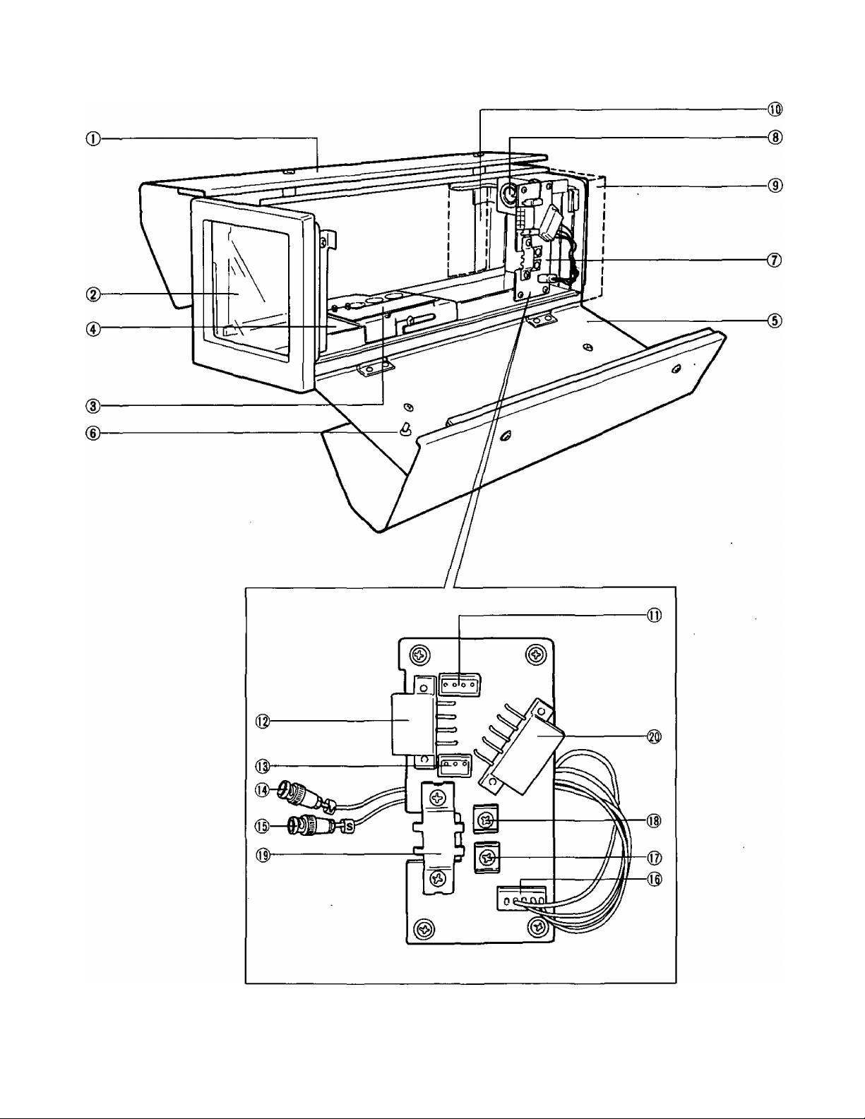
MAJOR OPERATING CONTROLS AND THEIR FUNCTIONS
_2-
Page 4

(1) Sunshleld
(2) Front Glass
(3) Camera Mounting Plate
(4) Heater Unit (Optional)
(5) Cover
(6) Cover Lock
(7) Connection Board
(8) Lens Connector
(9) Fan Unit (Optional)
(10) Sensor Board (Optional)
(11) Connector for the Fan/Heater Unit (4p) - CN4
(12) Housing Control - 1. (8p) - CN2
1. Camera Power 5. AC Common
2. Fan/Heater 6. ^/C
3. N/C 7. N/C
4. N/C 8. GND
INSTALLATION OF CAMERA
HOUSING
When mounting the Camera Housing to the Pan/Tilt
Head WV-7260D.
• Two M8 X 20 mm (5/16" x 13/16") hex head bolts,
lockwasheres and plain washers are provided with the
Pan/Tilt Head. Use these to mount the camera housing
as shown below.
(13) Camera Power Supply Connector (3p) - CN3
1. Camera Power
2. AC Common
3. GND
(14) Video Connector - BNC (V)
Connect to Video output of the camera.
(15) Sync Connector - BNC (S)
Connect to GEN LOCK input of the camera.
(16) Connector for Zoom Lens (5p)
1. DC Common 4. Zoom Control
2. Iris Control 5. N/C
3. Focus Control
(17) Video Output Terminal
(18) External Sync Input Terminal
(19) GND
(20) Housing Control - 2 (lOp) - CN1
1. N/C 6. N/C
2. N/C
3. N/C
4. N/C 9. Focus Control
5. N/C
7. DC Common
8. Iris Control
10. Zoom Control
• Be sure to align the camera direction and front direction
of Pan/Tilt Head.
-3-
Page 5

PREPARATION OF WIRING
1. Open the side cover with the flat head screw driver.
2. Fix the camera mounting plate on the bottom of the
camera using two screws.
M5 (plastic screw) is used as a stopper for the camera
from rotating except WV-BL90, WV-CL110.
This position should be changed by selection of the
camera and lens.
A: Cameras used with a fixed focus lens.
B: WV-BL90/WV-CL110 with WV-LZ81 /6 lens.
C; Cameras with WV-LZ81/6 tens.
2. Decide the wiring hole size for the rubber bushing, then
cut the bushing at the appropriate size. The minimum
hole size is 13/16 (20 mm).
To the terminal strip
Cut here —
if necessary
Min. Inner Diameter
013/16" (020)
L Bushing
Multi-conductor
cable and coax, cable
from Pan/Ti!t Head or
custom made remote controller.
REAR
Pass the cables through the wiring hole.
INSTALLATION OF CAMERA
1. Loose M4 screw to remove the camera mounting plate.
Camera
Make sure
this position
to be fixed.
Camera Mounting
Plate
Chassis
CAUTION:
Mount the camera (with mounting plate) on this
unit carefully.
When the camera LED reflects on the glass and
the light comes in the screen, stick the Power
Indicator Masking Label (accessory) on the LED.
APPLICABLE CAMERAS AND
LENSES
The recomended combination of the Panasonic camera and
lens to WV-7140 is shown in the following table.
Lens
Camera Fixed
WV-CD24
WV-BD404
WV-BL204
WV-CL304
WV-BL604
WV-CL704
WV-BL90
WV-CL110
-
-
•
0
o
0
•
•
for 1/2' camera
WV-L201/6 Fixed
-
0 •
0
0 o
0 o
•
•
for 2/3' camera
o
o
0
X
X
- 4 -
x: Inhibited combination in size
o: Recommended combination in size
•: Possible combination but remains much space inside
of housing.
Caution:
The Fan/Heater unit (WV-7141) should be required in
consideration of the ambient operating temperature
with the camera and the lens.
Page 6

CONNECTION OF CAMERA
1. Connect the camera power cable [Provided) to the camera and the Connection Board.
2. Cut off the cable clamp of the co-axial Cables.
Then connect the BNC cable which is marked (V) to the output of the camera. And if it is necessary, also connect the BNC
cable which is marked (S) to the GEN LOCK of the camera for external sync.
Caution:
Be sure to connect the power cable with the right position of the AC terminal strip on the camera.
Green - GND
Red -1
Black - 2
3. Clamp BNC connectors again not to touch the metal part to the electrical components.
WIRING OF CABLES
-5-
Page 7

B. Cable Information
• The length of wires. (Approx.)
L1: 2-1/2’ L5:6’
L2: 2’
L3: 12"
L6: 6*
L7: V
L4: 65’
2. In case of using the accesory connectors
(MX5557P08 and MX5557P10)
Select a multi-conductor cable which meets FR-1 rating
with 8 or 11 wires cables for WV-7140. A 11 wires cable is
used to extend the cable length.
Connect the 8 or 11 wires cable to the following position of
the accessory connectors.
CN Pin No.
WV-7140
CN2-1
CN2-2(3)
CN2-5(6)(7)
CN1-7
CN1-8
CN1-9
CN1-10
CN2-8
Usage of Terminal
24V AC CAMERA
FAN HEATER
AC COMMON
DCCOMMON
IRIS CONTROL
FOCUS CONTROL
ZOOM CONTROL
GND
Parts name
1.
18 wires cable
14 pin connector
2.
12 pin connector
3.
10 pin connector
4.
8 pin connector
5.
BNC connector
6.
• The length of the cable is determined by the chart
below. {The system should be operated by 24V AC and
the power consumption should have less than 11W for
the camera, 44W for WV-7141.)
Model WV-7140
Number of Conductors
Copper wire gauge /WG No.
#24
#22
#20 ft
#18
8 wires
ft 26 60
m 6 15
ft 40 05
m 10 25
60 150
m 15 45
ft 100 250
m 30 70
11 wires
• If 11 wires cable are available for WV-7140 connect
the remained 3 wires to the { ) position.
”1
9 £
lO
The accessory connectors view from wiring side.
i 7
6
4 :
5
CN1
1
) 2
8 7 6 5
4
2
3
CN2
1
• The above lengths are approximate.
• When the camera housing is mounted on the Pan/Tilt
Head WV-7260D, refer to the operating instructions of
it.
CAUTION:
CONNECT TO 24V AC CLASS 2 SUPPLY ONLY.
Caution: To prevent fire or shock hazard,
the UL listed wire VW-1, style 1007
should be used for the cable for AC
24V Input Terminal.
-6-
Page 8

• How to assemble the cable
1. strip back the cable jacket no more than 0,1 inches (3
mm) and separate the individual conductors.
2. Prepare the individual conductors for soldering or
clamping. If clamping, use MOREX tool part
number 57027-5000 {for UL-style cable UL1015) or
57026-5000 (for UL-Style cable UL1007)
Approx.
Contact
0.1 inch
^ insert
Insert the wire until A position
and clamp the contacts.
Wire
3. After soldering or clamping the contacts, push them
into the proper holes in the connector housing until
they snap in place.
Up
t
Contact
Caution:
• Clamping the contact is a one-time procedure.
• CONNECT TO 24VAC CLASS 2 SUPPLY ONLY.
Caution: To prevent fire or shock hazard,
the UL listed wire VW-1, style 1007
should be used for the cable for AC
24V Input Terminal.
INSTALLATION OF ZOOM LENS (WV-LZ81/6)
1. Connect the cable from the lens to female Harschman connector on the rear panel.
2. When a zoom lens of other brand is used, change the connector with the provided Harschman connector.
Refer to the pin configuratioa
Wire
Rn configuration
1 DC COM
2 IRIS
3 FOCUS
4 ZOOM
CAUTION:
• Clamp the cables not to contact with the heater unit or other electrical components.
TYPICAL SYSTEM CONNECTIONS
System Controller
WV-CU254
^ ^ .A. ‘
II _ B B o
Monitor
U,
Coax. Cable
AC 120V 60Hz
AC 120V
60Hz
Page 9

OUTLINE DRAWING
7/8'
SPECIFICATIONS
Power source:
Mounting;
Pan/tilt head:
System controller:
Receiver:
Ambient operating temperature:
Weight:
Dimensions:
24V AC 60 Hz
Rom bottom
WV-7260D (Optional)
WV-CU254 (Optional)
WV-RC150 (Optional)
LOW: -22°F (-30°C) when WV-7141 is used with.
HIGH: Refer to the specifications of the camera and the lens.
Approx. 6.6 lbs (3 kg)
5-5/8"(W) X 5-5/16"(H) X 20-1/16‘(D) (Approx.)
[142(W) X 135(H) X 510(D) mm]
STANDARD ACCESSORIES (Supplied)
Camera Holding Screw
(Plastic screw)
Camera,Mounting screw ...............................................1 pc.
(with insulation washer)
Clamping wire ...................................................-.
.............•..................................
.......
1 pc.
4 pcs.
Lens Connector [Part No. YWMAS4100] .......................1 pc.
Power Indicator Masking Label ......................................1 pc.
Power Cable for 24V AC Camera
Connector [MX5557P08] ................................................1 pc.
1MX5557P10]
..................................
..............................................
1 pc.
1 pc.
-8-
Page 10

Panasonic
Communications & Systems Company
Panasonic Communications & Systems Company
Division of Matsushita Electric Corporation of America
CLOSED CIRCUIT VIDEO EQUIPMENT DIVISION
HEADQUARTERS:
50 Meadowiand ParKway, Secaucua, Naw Jersey 07094
EASTERN ZONE:
SO Meadowiand Parkway. Secaocus. NJ 07094 (201) 348-7620
CENTRAL ZONE;
425 E. Algonquin Road, Arlington Hts. IL 60005 (708) 981-4826
SOUTHERN-ZONE:
Dallas Region: 4500 Amon Carter Btvd., Ft Worth, TX 76155 (817) 685-1117
Atlanta Flegion; tS54 Shackleford Cl. Suita 115 Norcroas. GA 30003 (404) 025-6841
WESTERN ZONE:
Seattle Region: 1200 Westlake Ave. N.. Suits 508. Seattle. WA 98109 (206) 285-8883
Los Angeles Region: 6550 Katolla Ave.. Cypress. CA 90630 (714) 373-7275
MATSUSHITA ELECTRIC OF CANADA LIMITED
5770 Ambler Drive, Mississau((a. Ontario. Canada LAW 2T3 (416) 624-5010
PANASONIC SALES COMPANY
DIVISION OF MATSUSHITA ELECTRIC OF PUERTO RICO, INC.
San Gabriel Industrial Park, 65th Infantry, Ave. KM. 9.5 Carolina, Puerto Rico 00630 (809) 750-4300
N1189-1020
YWV8QA2011BN
Printed in Japan
(S> 15
 Loading...