

Page 1
WS-AT300
RAMSd
Speaker System
WS-AT300
Subwoofer System
WS-AT350
Operating
WS-AT350
Inductions
Panasonic
Beton «nempwtg le «meet or opweic ft* pKxluci »«ise i*ed rwxiKr» cfl»*i*«ciy
CONTENTS
REGULATORY STATEMENTS ...........................................................................2
SAFETY INSTRUCTIONS................................................................................... 2
PREFACE ............................................................................................................3
PRECAUTIONS....................................................................................................3
INSTALLING THE SPEAKER .............................................................................4
CONNECTING SPEAKER CABLES
WIRING CONNECTOR AND CABLE ..................................................................7
SETTING THE SUBWOOFER PROCESSOR
PROTECTION CIRCUITS FOR WS-AT300.........................................................8
BLOCK DIAGRAM ...............................................................................................9
SPECIFICATIONS................................................................................................9
TYPICAL PERFORMANCE................................................................................10
DIRECTIVITY ....................................................................................................10
APPEARANCE ................................................................................................. 11
..................................................................
....................................................
6
8
Page 2

REGULATORY STATEMENTS
WARNING:
TO PREVENT FIRE OR ELECTRIC SHOCK HAZARD,
DO NOT EXPOSE THIS APPLIANCE TO RAIN OR
MOISTURE>
The serial number of this product may be found on the back
of the unit.
You should note the serial number of this unit in the space
provided and retain this book as a permanent record of your
purchase to aid identification in the event of theft.
Model No.____________________________________________
Serial No.---------------------------------------------------------------------------
SAFETY INSTRUCTIONS
Please observe the following instructions carefully for your own safety and that of equipment.
• If the speakers fall, it can cause serious damage to persons or properties.
• Read the instructions printed on the back of the speakers.
• Ask your nearest dealer or qualified installers for installation and wiring.
• Place the speakers on a stable surface.
• Secure the speakers with safety wires or equivalent.
• Detach the speaker and the speaker stand before adjusting their height.
• Separate the speaker and the speaker stand before moving the set to a different location.
• Do not install the speaker with the stand at a place where passers-by might stumble on them.
-2-
Page 3

PREFACE
WS-AT300
• This speaker system is a 2-way bass-reflex type
incorporating a 38-cm (15”) woofer and a Square
Contour Wave Guide (SCWG) horn tweeter.
• The speaker system accepts a continuous program
input of 400 W or 200 W(RMS). It delivers high
outputs from its compact body with a maximum
sound pressure level of 122 dB.
• The SCWG horn minimizes the disturbing reflection
sound generated near the open end and to provide
a constant directivity of 60‘ (horizontal) and 40“
(vertical). You can easily attach again the horn to
the enclosure by turning it 90' as required for
horizontal or vertical speaker installation,
• The enclosure has essential features such as
toughness to transportation, a recessed type
handle for carrying, the convex and concave for
stacking, holes for mounting bracket, safety wires,
etc.
WS-AT350
• This Subwoofer is a bass-reflex type incorporating
a 38-cm (15”) cone speaker and to be used with
the RAMSA Subwoofer Processor WS-SP2A.
• The WS-AT350 accepts an input of 400 W (RMS). It
delivers high outputs, though it is small in size, with
a maximum sound pressure level of 118 dB.
• The enclosure has essential features such as
toughness to transportation, a recessed type
handle for carrying, the convex and concave for
stacking, holes for mounting bracket, safety wires,
etc.
PRECAUTIONS
Power loss may increase as the total speaker
impedance gets lower with a number of speaker
hookups. Use the largest speaker cable in wire
gauge to reduce power ioss.
Switch off the power amplifiers before connecting
the speakers or other peripherals.
Avoid the followings all the time to protect the
speakers from damage.
• Turning on and off mixing consoles and other
peripherals may cause shock noise when the'
amplifiers and subwoofer processor are on.
• Shock noise resulting from the connection/
disconnection of inputs/outputs with any
powered-up equipment
• Pop noise from microphones without
appropriate use of breath-pop screen and/or
high-pass filter
• Click noise caused by switching on or off the
phantom power for microphones
• Continuous operation at very low frequency
from an oscillator, synthesizer or program
sources
• High frequency noise deveioped by fastforward or fast-rewind operation of a tapedeck
■ Out of tune noise in FM broadcast
• Feed-back from microphones or electronics
musical instruments.
Match the polarities of all the speakers by
observing the connectors and wire colors when
using two or more speakers.
Read “PROTECTION CIRCUITS" on page 8. Turn
down the volume control of the amplifier
immediately if the sound suddenly decreases.
You should use the WS-AT350 Subwoofer all the
time with Subwoofer Processor WS-SP2A. The WSSP2A processes the signal to protect the speakers
from damage due to an excessive input signal.
-3-
Page 4
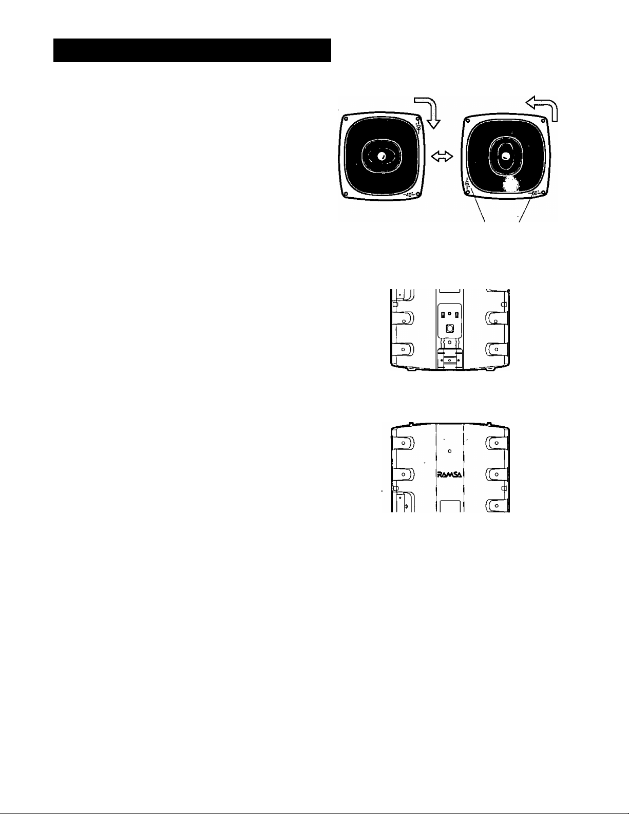
INSTALLING THE SPEAKER
• Changing the tweeter direction
You can alter the directivity when placing the WSAT300 horizontally.
1. Unscrew four bolts to detach the tweeter.
2. Turn the tweeter by 90°.
3. Tighten four bolts to attach the tweeter again.
4. Rotate the RAMSA badge by 90°.
Stacking
Speakers can be stacked one upon another as
illustrated.
Place an additional speaker on top of another, making
sure to match their convex and concave portions.
Sound dispersion angles
ж
-4-
Page 5

INSTALLING THE SPEAKER
• On wall or ceiling
You can install the speaker on a wall or ceiling with a
mounting bracket (not supplied).
® Place the bracket on the enclosure.
C D
Screw the eye bolts into the screw holes of the
enclosure by hand.
(D Fix the speaker to a wall or ceiling.
@ Take safety protections mentioned in "Secure the
speaker."
Note: Installers should seek advice on the building
structure and load capacity, if unknown, from
an architect or a structural engineer.
• Secure the Speaker
Use safety wires (not supplied) when hanging the
speaker from a wall or ceiling. This is not a major
means of support but just a safety relief.
® Tighten the eye bolts with washers and bolt nuts
(not supplied) into the screw holes of the enclosure
by hand.
Hand
tighten ®
Washer
Set direction
^ Tighten with wrench CD
( D
Eye Bolt
Bolt nut
(D Set the direction of the eye bolts to be in the best
position for binding safety wires.
C D
Fasten the bolt nuts with wrench.
(3) Bind one end of safety wires to the eye bolts.
(D Secure the other end of safety wires to the
supporting structure of the building.
• Mounting on a stand
1. You can mount the speaker on a speaker stand by
using the stand hole in the enclosure bottom.
2. The stand should have a supporting pipe of o1.5
inches.
3. Take safety protections by placing it in a safety
location, for example.
Stand hole
(Bottom side)
-5-
Page 6

CONNECTING SPEAKER CABLES
You can find the TS (tip-sleeve) phone jack and
SPEAKON connector on the back of the enclosure.
These two are usable as input or output terminals since
they are wired in parallel. See the block diagram on
page 9.
1. Connect signal input from an amplifier to either TS
phone jack or SPEAKON connector.
TS phone jack
........ .. . ^
From
amplifier
From
amplifier
2. Bridge the first speaker and the second when using
two speakers in parallel as illustrated.
Notes:
• Do not connect more than two speakers in parallel.
Excessively low impedance can cause distorted
output sound or damage to the amplifier.
• Match the sound phase of all speakers by
confirming the polarities of connection when using
two or more speakers.
From
amplifier
From
amplifier
-6-
Page 7

WIRING CONNECTOR AND CABLE
TS (tip-sleeve) phone plug
1. Unscrew the plug cover.
2. Thread speaker cables through the plug cover.
3. Connect and solder the + (positive) polarity wire to
the tip of the plug.
4. Connect and solder the - (negative) polarity wire to
the sleeve of the plug.
5. Tighten cable with the clamp of the plug.
6. Fasten the plug cover.
SPEAKON connector
Use SPEAKON connector (4-pole, NL4FC series, by
NEUTRIK AG) as followings.
® Unscrew the connector cap by rotating it
counterclockwise.
(D Slide the cable clamp out from the rear of the
connector.
(3) Push and separate the connector sleeve from the
terminal block.
® Pass the connector cap arid cable clamp over the
end of the cable.
® Loosen the clamping screws in the terminal block.
® Prepare and insert the wires into the terminals as
shown in the table.
@ Tighten the screws to secure the wires.
Plug Cover 0 Sleeve
Speaker Cable
Tamninat block
AMP OUT SPEAKON
+ 1 +
(Not used)
(Not used) 2-
1 -
2 +
AMP OUT
+
-
Push
©Tip
Plug
Tip
Sleeve
Cable clamp
@
Connector sleeve
Loosen screws.
®
® For added security in portable applications,
soldering of the wires together with the terminals is
recommended.
® Assemble the terminal block and the connector
sleeve after matching the positions of the concave
and the convex.
® Match the convex position of the cable clamp to the
concave of the connector sleeve, then push the
cable clamp.
® Screw the connector cap.
®
®
Push Cable clamp
-7-
Page 8

SEHING THE SUBWOOFER PROCESSOR
For further details please refer to the Operating Instructions of the RAMSA Subwoofer Processor WS-SP2A.
RECOMMENDED FUNCTION SELECTOR SETTING
SUB WOOFER MAIN SPEAKER FUNCTION SELECTOR POSITION
1 2 3 1 2 3
t £. vJ 1—^ Ì £ •u
0
S I SsLd
WS-AT350 WS-AT300
VLFI
cc cc
PROTECTION CIRCUITS FOR WS-AT300
• The WS-AT300 has separate overload protection
circuits for woofer and tweeter. 'When activated by an
excessive input signal, they mute the output sound.
Turn down the volume control for 2 to 20 seconds to
reset the circuits.
Note: Make sure to lower the volume control of the
amplifiers if the output sound suddenly decreases.
Keeping or even increasing the volume can cause
serious damage to the speaker.
A K 1 2 3
b_Ld
1
m
SYSTEM DIAGRAM
This shows an example of system connections.
Audio
Mixer
In A
In B
WS-AT300
WS-AT350
-8-
Page 9

BLOCK DIAGRAM
WS-AT300
Phone jack
SPEAKON
Connector
WS-AT350
SPECIFICATIONS
Type
Input impedance
Power capacity
Sound Pressure Level
Max. Sound Pressure Level
Frequency response
Crossover frequency
Speaker
Woofer
Tweeter
Dispersion
Dimensions
Weight
Finish
Enclosure
Front panel
Standard accessories '
2 Way, Bass-reflex type
400 W (continuous program input)
200 W (RMS)
99 dB[1 W, 1m (3.3 ft)]
122dB[1m(3.3ft)]
70 Hz - 18 000 Hz
2 200 Hz
38 cm (15") cone speaker
SCWG horn speaker
60° (horizontal), 40° (vertical)
480 (W) X 694 (H) x38 (D) mm [18-7/8"
26 kg (57 tbs.)
Eyebolt (M8 X 25) ............................................2
Operating Instructions
WS-AT300
.....................................
Tweeter
Woofer
Woofer
WS-AT350. .
Bass-ref lex, type"
8 ohms
400W (RMS)
—
92 dB [1 W, 1m (3.3 ft)]
118dB[1m(3.3 ft)]
30 Hz - 1 400 Hz
—
38 cm (15") cone speaker
—
—■
(W) X 27-5/16” (H)x 15" (D)]
26.5 kg (58 lbs.)
Resin molded. Blue black
Punched grille, Blue black
1
Dimensions and weight indicated are approximate.
Specifications are subject to change without notice.
True effective power measured by the test method prescribed by American National Standard EIA (Electronic Industries
Association), RS-426-A (1980).
In this test, the noise signal with a higher frequency power component was used to match the latest programme
sources.
-9-
Page 10

TYPICAL PERFORMANCE
IWS-AT300
(dB) (1w, 1m)
Frequency
WS-AT350
10 20
50 100 200 500 1000 2000 5000 10000 20000
32fl
16fl
6n
Frequency
DIRECTIVITY
WS-AT300
270*
240*
-10-
Page 11

APPEARANCE
WS-AT300
Unit: mm [inch]
WS-AT350
-11-
Page 12

Panasonic
Broadcast & Television Systems Company
Division o1 Matsushita Electric Corporation of Anrterica
RAMSA/Professional Audio Systems
Executive Office: One Panasonic VJay, Secaucus, New Jeiley 07094
5770 Ambler Drive. Mississauga. Ontario, L4W 2T3 Canada (905) 624-5010
PANASONIC CANADA INC.
PANASONIC SALES COMPANY
DIVISION OF MATSUSHITA ELECTRIC OF PUERTO RICO, INC.
San Gabriel Industrial Park, 65th Infantry Ave. KM. 9.5 Carolina. Puerto Rico 00630 (809) 750-4300
6550 Katella Av0. 17A-7, Cypress, CA 90630 (714) 373*7277
Ns 1197-0 YWA8QA4784AN Printed in Japan
 Loading...