

Page 1
Before attempting to connect or operate this product,
please read these instructions carefully and save this manual for future use.
Model No. WR-XS3
Audio Mixer
Operating Instructions
Page 2
2
The serial number of this product may be found on the bottom of the unit.
You should note the serial number of this unit in the space
provided and retain this book as a permanent record of your
purchase to aid identification in the event of theft.
Model No. WR-XS3
Serial No.
Caution:
Before attempting to connect or operate this product,
please read the label on the bottom.
NOTE: This equipment has been tested and found to comply with the limits for a Class A digital device, pursuant to
Part 15 of the FCC Rules. These limits are designed to provide reasonable protection against harmful interference
when the equipment is operated in a commercial environment. This equipment generates, uses, and can radiate
radio frequency energy and, if not installed and used in
accordance with the instruction manual, may cause harmful
interference to radio communications.
Operation of this equipment in a residential area is likely to
cause harmful interference in which case the user will be
required to correct the interference at his own expense.
FCC Caution: To assure continued compliance, (example use only shielded interface cables when connecting to computer or peripheral devices). Any changes or modifications
not expressly approved by the party responsible for compliance could void the user's authority to operate this equipment.
For U.S.A
WARNING:
To reduce the risk of fire or electric shock, do not expose this appliance to rain or moisture.
CAUTION: TO REDUCE THE RISK OF ELECTRIC SHOCK,
DO NOT REMOVE COVER (OR BACK).
NO USER-SERVICEABLE PARTS INSIDE.
REFER SERVICING TO QUALIFIED SERVICE PERSONNEL.
CAUTION
RISK OF ELECTRIC SHOCK
DO NOT OPEN
The lightning flash with arrowhead symbol,
within an equilateral triangle, is intended to
alert the user to the presence of uninsulated
"dangerous voltage" within the product's
enclosure that may be of sufficient magnitude to constitute a risk of electric shock to
persons.
The exclamation point within an equilateral
triangle is intended to alert the user to the
presence of important operating and maintenance (servicing) instructions in the literature accompanying the appliance.
Power disconnection. Unit with or without
ON-OFF switches have power supplied to
the unit whenever the power cord is inserted
into the power source; however, the unit is
operational only when the ON-OFF switch is
in the ON position. The power cord is the
main power disconnect for all units.
SA 1965
SA 1966
(For U.S.A. and Canada)
The model numbers in these Operating Instructions are
given without suffix.
Page 3
3
Wij verklaren als enige aansprakelijke, dat het product waarop deze
verklaring betrekking heeft, voldoet aan de volgende normen of andere
normatieve documenten, overeenkomstig de bepalingen van Richtlijnen
73/23/EEC en 89/336/EEC.
Vi erklærer os eneansvarlige for, at dette produkt, som denne deklaration omhandler, er i overensstemmelse med standarder eller andre normative dokumenter i følge bestemmelserne i direktivene 73/23/EEC og
89/336/EEC.
Vi deklarerar härmed värt fulla ansvar för att den produkt till vilken
denna deklaration hänvisar är i överensstämmelse med standarddokument, eller andra normativa dokument som framställs i EEC-direktiv nr.
73/23 och 89/336.
Ilmoitamme yksinomaisella vastuullamme, että tuote, jota tämä ilmoitus
koskee, noudattaa seuraavia standardeja tai muita ohjeellisia asiakirjoja,
jotka noudattavat direktiivien 73/23/EEC ja 89/336/EE. säädöksiä.
Vi erklærer oss alene ansvarlige for at produktet som denne erklæringen
gjelder for, er i overensstemmelse med følgende normer eller andre normgivende dokumenter som følger bestemmelsene i direktivene
73/23/EEC og 89/336/EEC.
We declare under our sole responsibility that the product to which this
declaration relates is in conformity with the standards or other normative
documents following the provisions of Directives EEC/73/23 and
EEC/89/336.
Nosotros declaramos bajo nuestra única responsabilidad que el producto a que hace referencia esta declaración está conforme con las normas
u otros documentos normativos siguiendo las estipulaciones de las
directivas CEE/73/23 y CEE/89/336.
Noi dichiariamo sotto nostra esclusiva responsabilità che il prodotto a
cui si riferisce la presente dichiarazione risulta conforme ai seguenti
standard o altri documenti normativi conformi alle disposizioni delle
direttive CEE/73/23 e CEE/89/336.
Wir erklären in alleiniger Verantwortung, daß das Produkt, auf das sich
diese Erklärung bezieht, mit der folgenden Normen oder normativen
Dokumenten übereinstimmt. Gemäß den Bestimmungen der Richtlinie
73/23/EEC und 89/336/EEC.
Nous déclarons sous note seule responsabilité que le produit auquel se
réfère la présente déclaration est conforme aux normes ou autres documents normatifs conformément aux dispositions des directives
CEE/73/23 et CEE/89/336.
The serial number of this product may be found on the
bottom of the unit.
You should note the serial number of this unit in the
space provided and retain this book as a permanent
record of your purchase to aid identification in the event
of theft.
Model No. WR-XS3
Serial No.
The lightning flash with arrowhead symbol, within an equilateral triangle, is
interned to alert the user to the presence
of uninsulated "dangerous voltage" within the product's enclosure that may be of
sufficient magnitude to constitute a risk
of electric shock to persons.
The exclamation point within an equilateral triangle is intended to alert the user
to the presence of important operating
and maintenance (servicing) instructions
in the literature accompanying the appliance.
Power disconnection. Unit with or without ON-OFF switches have power supplied to the unit whenever the power
cord is inserted into the power source;
however, the unit is operational only
when the ON-OFF switch is in the ON
position. The power cord is the main
power disconnect for all units.
CAUTION: TO REDUCE THE RISK OF ELECTRIC SHOCK,
DO NOT REMOVE COVER (OR BACK).
NO USER-SERVICEABLE PARTS INSIDE.
REFER SERVICING TO QUALIFIED SERVICE PERSONNEL.
CAUTION
RISK OF ELECTRIC SHOCK
DO NOT OPEN
CAUTION:
Before attempting to connect or operate this product, please read the label on the bottom.
WARNING:
To reduce the risk of fire or electric shock, do not expose this appliance to rain or moisture.
FOR YOUR SAFETY PLEASE READ THE FOLLOWING TEXT CAREFULLY.
WARNING: This apparatus must be earthed.
IMPORTANT
The wires in this mains lead are coloured in accordance with the following code.
Green-and-yellow: Earth
Blue: Neutral
Brown: Live
As the colours of the wire in the mains lead of this appliance may not
correspond with the coloured markings identifying the terminals in your
plug, proceed as follows.
The wire which is coloured green-and-yellow must be connected to
the terminal in the plug which is marked with the letter E or by the earth
symbol
I or coloured green or green-and-yellow.
The wire which is coloured blue must be connected to the terminal in
the plug which is marked with the letter N or coloured black.
The wire which is coloured brown must be connected to the terminal
in the plug which is marked with the letter L or coloured red.
(Except for U.S.A. and Canada)
The model numbers in these Operating Instructions are given
without suffix.
Page 4

4
1) Read these instructions.
2) Keep these instructions.
3) Heed all warnings.
4) Follow all instructions.
5) Do not use this apparatus near water.
6) Clean only with dry cloth.
7) Do not block any ventilation openings. Install in accordance with the manufacturer's instructions.
8) Do not use near any heat sources such as radiators, heat registers, stoves or other apparatus (including amplifiers) that
produce heat.
9) Do not defeat the safety purpose of the polarized or grounding-type plug. A polarized plug has two blades with one wider
than the other. A grounding-type plug has two blades and a third grounding prong. The wide blade or the third prong are
provided for your safety. If the provided plug does not fit into your outlet, consult an electrician for replacement of the
obsolete outlet.
10) Protect the power cord from being walked on or pinched particularly at plugs, convenience receptacles and the points
where they exit from the apparatus.
11) Only use attachments/accessories specified by the manufacturer.
12) Use only with the cart, stand, tripod, bracket or table specified by the manufacturer or sold with the apparatus. When a cart
is used, use caution when moving the cart/apparatus combination to avoid injury from tip-overs.
13) Unplug this apparatus during lightning storms or when unused for long periods of time.
14) Refer all servicing to qualified service personnel. Servicing is required when the apparatus has been damaged in any way,
such as power-supply cord or plug is damaged, liquid has been spilled or objects fallen into the apparatus, the apparatus
has been exposed to rain or moisture, does not operate normally, or has been dropped.
IMPORTANT SAFETY INSTRUCTIONS
S3125A
Page 5

5
CONTENTS
IMPORTANT SAFETY INSTRUCTIONS ............................4
PREFACE ............................................................................6
FEATURES .........................................................................6
PRECAUTIONS ...................................................................7
MAJOR OPERATING CONTROLS
AND THEIR FUNCTIONS ...................................................8
■ Front View .....................................................................8
■ Rear View .....................................................................9
INSTALLATION ................................................................11
■ Work Flow ....................................................................11
■ Before Installation .......................................................11
● Power Connection ..................................................11
● Installation Place .....................................................11
● Rack Mounting ........................................................11
● Grounding the Unit ................................................11
● Condenser Microphone .........................................11
■ Mounting into the Rack ...............................................12
■ Cable Information .......................................................13
SETUP PROCEDURES .....................................................14
■ Unit Modes and Signal Flow .......................................14
● Mode 1 ....................................................................14
● Mode 2 ....................................................................16
● Mode 3 ....................................................................17
■ Input Line Setting for SUB OUTPUT ...........................18
■ Output Line Setting for MULTI IN/LINE IN ..................19
CONNECTION EXAMPLES ..............................................21
■ Example 1: Home Party (Mode 1) ...............................21
■ Example 2: Presentation Room (Mode 2)....................22
■ Example 3: Shop (Mode 3) .........................................23
RECORDER CONNECTIONS ...........................................24
■ Notice about Recorder Connections .........................24
● When Using a Recording-only
and a Playback-only Decks.....................................24
● When Recording and Playing Back
with One Deck .........................................................24
■ Using a Recording-only and a Playback-only Decks .24
■ Recording and Playback with One Deck ...................25
STICKING LABELS ..........................................................26
■ Label ...........................................................................26
■ Where to Stick Labels .................................................26
■ Indication of Input Line Assigned to SUB OUT ..........27
ATTACHING/DETACHING THE ACRYLIC COVER ........28
OPERATIONS ...................................................................29
■ Basic Operation ..........................................................29
■ Input Level Adjustment ...............................................30
■ Using CD/MD Player through LINE IN ........................31
BLOCK DIAGRAM ............................................................32
■ MODE1 .......................................................................33
■ MODE 2 ......................................................................34
■ MODE 3 .......................................................................35
LEVEL DIAGRAM ..............................................................36
TROUBLESHOOTING ......................................................37
SPECIFICATIONS .............................................................38
STANDARD ACCESSORIES ...........................................38
Page 6

6
This audio mixer has four mono input lines, four stereo input lines, one mono/stereo input line and three output lines.
FEATURES
● Three modes applicable to different amplification systems
DIP switches at the rear panel support the following amplification systems:
• Mode 1: One-circuit amplification (stereo: 1 and mono: 1)
• Mode 2: Two-circuit amplification (stereo: 1 or mono: 1)
• Mode 3: Three-zone amplification (stereo: 1 and mono :2)
● Integrated level control of microphone sounds or BGM
The mono or stereo output level is adjustable with one knob: the MONO OUT or STEREO OUT knob.
● Customizable amplification systems
• The SUB OUTPUT connector can be assigned to a desired input line from among the STEREO INPUT jack 1 to 4, the connectors MONO INPUT 1 to 4, and the MULTI IN STEREO/MONO jack. Refer to p. 18 Output Line Setting for SUB OUTPUT
for details.
• The MULTI INPUT* ST and the MULTI INPUT MONO jacks serve as additional stereo or mono input lines, as they can be
assigned to any output line.
• The LINE IN* jack at the front panel can be connected to a personal computer, MD player or CD player.
* The signal from MULTI INPUT ST/MONO jack(s) and the LINE IN jack are unavailable at the same time. (The LINE IN jack
has a priority to MULTI IN.)
● Basic functions
• Head amplifier with discrete construction (mono input)
• Electronically balanced output circuit
• Design for noise reduction and sound quality improvement (Refer to p. 38 SPECIFICATIONS.)
• Stereo input auto mute switch, used for information broadcasting in a shop
• Acrylic cover is attachable on the front panel to prevent wrong operation.
Note: In these Operating Instructions, "Mono" and "mono" stand for "monophonic".
PREF ACE
Page 7

7
PRECAUTIONS
• Refer all work related to installation of this product
to qualified service personnel or system installers.
• Turning On the Power
Turn on the unit before the amplifier is turned on.
• Turning Off the Power
Turn off the amplifier first, and then turn off the unit.
• Connection
Switch off the amplifier, the unit and any other devices
before connection to prevent speaker damage.
•Do not attempt to disassemble the appliance.
To prevent electric shock, do not remove screws or
covers.
There are no user-serviceable parts inside. Refer maintenance to qualified service personnel.
• Handle the appliance with care.
Do not strike or shake, as this may damage the appliance.
• Do not expose the appliance to water or moisture,
nor try to operate in wet water.
Do take immediate action if the appliance becomes
wet. Turn the power off and refer servicing to qualified
service personnel. Moisture can damage the appliance
and also cause electric shock.
• Do not use strong abrasive detergent when cleaning
the appliance body.
Use a dry cloth to clean the appliance when it is dirty.
When the dirt is hard to remove, use a mild detergent
and wipe it gently.
• Do not operate the appliance beyond its specified
temperature, humidity or power source ratings.
Do not use the appliance in an extreme environment
where high temperature or high humidity exists.
Use the appliance at temperatures within 0 °C - +45 °C
(32 °F - 113 °F) and a humidity below 90 %.
The input power source for WR-XS3 is 120 V AC, 60 Hz
or 220 - 240 V AC, 50 Hz.*
* Power supply is not switchable but conformed to your
area.
Page 8
8
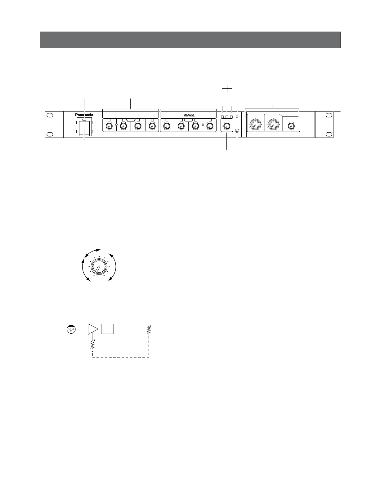
MAJOR OPERATING CONTROLS AND THEIR FUNCTIONS
■ Front View
q Power switch [POWER]
Toggles the power on and off.
w Power indicator
Lights up when the power switch is set to ON.
e Mono input level knobs [MONO 1 to 4]
Monaural input levels are adjustable with these knobs
corresponding widely to the connected devices, e.g.,
from microphones up to line-level source devices.
Input gains are in conjunction with output gains. (Duallevel control)
Note: When using Panasonic wireless microphones, set
the output level to –20 dB.
r Stereo input level knobs [STEREO 1 to 4]
Stereo input levels are adjustable with these knobs corresponding widely to the connected devices, e.g., from
microphones up to line-level source devices.
t Stereo output assign button [ST]
Assigns the signal inputs of the MULTI INPUT ST jack,
MULTI INPUT MONO connector, and LINE IN to
STEREO OUT jacks.
ON (;): These inputs are assigned to the STEREO
OUTPUT jack.
OFF(l): These inputs are not assigned to the STEREO
OUTPUT jack.
y Monaural output assign button [MONO]
Assigns the signal inputs of the MULTI INPUT ST jack,
the MULTI INPUT MONO connector, and the LINE IN
jack to MONO OUTPUT jack.
ON (;): These inputs are assigned to MONO OUTPUT
jack.
OFF(l): These inputs are not assigned to MONO
OUTPUT jack.
u Sub output assign button [SUB]
Assigns the signal inputs of the MULTI IN STEREO
jacks, the MULTI INPUT MONO connector, and the
LINE IN jack to SUB OUTPUT jack.
ON (;): These inputs are assigned to SUB OUTPUT jack.
OFF (l): These inputs are not assigned to SUB
OUTPUT jack.
i Multiple input level knob [MULTI IN]
Multiple input level is adjustable corresponding widely
to the connected device.
o Line input jack [LINE IN]
Connects to an input device such as a CD player, MD
player or tape recorder.
Stereo/mono: 1 circuit
Output jack: Stereo mini jack
Input level: –10 dB
Impedance: 10 kΩ, unbalanced
4
28
100
1
6
4
28
100
2
6
4
28
100
3
6
4
28
100
4
6
MONO
POWER
4
28
100
1
6
4
28
100
2
6
4
28
100
3
6
4
28
100
4
6
4
4
228
8
100
100
6
6
ST
MULTI IN
4
28
100
6
SUB OUT
STEREO
MONO
STEREO OUT
INPUT
REAK
LINE IN
SUB
4
2
8
100
6
MONO OUT
Audio Mixer WR-XS3
w
Power indicator
q
Power switch
e
Mono input level knobs
r
Stereo input level knobs
t
i
Multiple input level knob
o
Line input jack
u
!1
Output level knobs
y!0
Input peak indicator
Multiple input / line input assign buttons
Wireless
maicrophone
6
4
Other input
devices
28
Microphone
100
HA HPF
MONO IN
–80 to –10dB
Page 9
9
!0Input peak indicator [INPUT PEAK]
Lights up when any input signal reaches –3 dB (from
the MONO INPUT 1 to 4 connectors, the STEREO
INPUT 1 to 4 jacks , the MULTI INPUT ST connectors,
the MULTI INPUT MONO connector and the LINE IN
jack) above the clip level.
!1 Output level knobs
[STEREO OUT]
Turning to the left will lower the stereo output level.
Turning to the right will raise the output level.
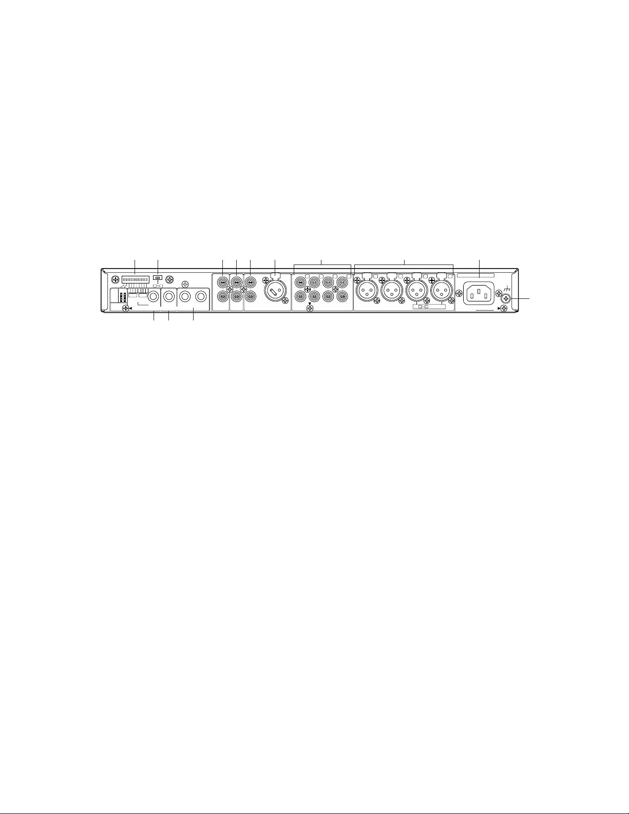
q DIP switches
Switches A and B select the unit mode from among
mode 1, 2 and 3.
Switches MONO 1 to 4 and STEREO 1 to 4 assign any
input lines to SUB OUTPUT jack.
Refer to pp. 15 to 18.
w Stereo input auto mute switch [ST 1- 4 AUTO MUTE]
Selects the auto mute setting when an input signal is
accepted via the MONO INPUT connector 1 or 2. Auto
mute is applicable to information broadcasting with
BGM in a shop.
ON (;): The volume(s) of the STEREO INPUT 1 to 4
jacks are automatically muted.
OFF (l): The volume(s) of the STEREO INPUT 1 to 4
jacks are not automatically muted.
Mute level: 9 dB
e Sub output jack [SUB OUTPUT]
Transmits a signal from a desired input line (from
among the STEREO INPUT 1 to 4 jacks, the MONO
INPUT 1 to 4 connectors, or the MULTI INPUT ST jacks)
which is mixed by the unit.
Mono: 1 circuit
Output jack: TRS jack electronic balanced
Output level: +4 dB
Impedance: 10 kΩ
r Mono output jack [MONO OUTPUT]
Transmits a mono signal mixed by the unit.
Mono: 1 circuit
Output jack: TRS jack electronic balanced
Ser No.
0dB is referenced to 0.775Vrms
AC IN
SIGNAL
GND
12341
L
R
1 4
ST AUTO MUTE
1 4
ST AUTO MUTE
MONO INPUT –60dB to –10dB 10kΩINPUT –10dBV 10kΩSTEREO
STEREO
PIN CONNECTION
MONO
INPUT
MODE
1
2
3
A
ON
OFF ON
No. 1: GND
No. 2: HOT
No. 3: COLD
OFF
43214321
MODE
SELECT
SELECT
STEREO
MONO
SUB
MONOST
MULTI INPUTSUB IN
REC OUT
–10dBV 10kΩ +4dB 10kΩ –10dBV 10kΩ
–45dB 10kΩ
234
L
R
L
LR
R
OUTPUT +4dB 10kΩ
B
q
er t
wyuio!0 !1 !2
!3
■ Rear View
[MONO OUT]
Turning to the left will lower the mono output level.
Turning to the right will raise the mono output level.
[SUB OUT]
Turning to the left will lower the sub output level.
Turning to the right will raise the output level.
Output level: +4 dB
Impedance: 10 kΩ
t Stereo output jacks [STEREO OUTPUT L/R]
These jacks transmit a stereo signal mixed by the unit.
Stereo: 1 circuit
Output jack: TRS jack electronic balanced
Output level: +4 dB
Impedance: 10 kΩ
y Recording output jacks [REC OUT L/R]
These jacks connect to a recording device such as a
stereo cassette recorder or MD recorder.
Stereo: 1 circuit
Output jack: RCA type pin jack unbalanced
Output level: –10 dBV
Impedance: 10 kΩ
u Sub input jacks [SUB IN L/R]
These jacks receive output signals from sub mixer, etc.
The signals input to these connectors are output
through the STEREO OUTPUT jack.
Stereo: 1 circuit
Input jack: RCA type pin jack unbalanced
Input level: +4 dB
Impedance: 10 kΩ
i Multiple stereo input jacks [MULTI INPUT ST L/R]
These jacks connect to audio-visual devices such as a
CD player and tape recorder.
Stereo: 1 circuit
Input jack: RCA type pin jack unbalanced
Page 10

10
Input level: –10 dBV
Impedance: 10 kΩ
o Multiple mono input connector [
MULTI INPUT MONO
]
Connects a microphone. When using this connector,
remove the short pin.
Mono: 1 circuit
Input connector: XLR-3-31 type balanced
Input level: –45 dB
Impedance: 10 kΩ
!0 Stereo input jacks [STEREO INPUT L/R 1 - 4]
These XRL connectors receive input signals from up to
4 audio-visual devices such as a CD player and tape
recorder.
Stereo: 4 circuits
Input jack: PIN jack unbalanced
Input level: –10 dBV
Impedance: 10 kΩ
!1 Mono input connectors [MONO INPUT 1 - 4]
These XLR connectors receive input signals from up to
4 microphones or other input devices.
Mono: 4 circuits
Input connector: XLR-3-31 type balanced
Input level: –10 dB to –60 dB
Impedance: 10 kΩ
!2 AC inlet socket [AC IN]
To use the unit, plug the power cord (supplied as a
standard accessory) into this socket and connect it to
an AC receptacle.
!3 Grounding screw [SIGNAL GND]
Notes:
• An RCA type pin plug cable is recommended for connection between the unit and a CD player through the
MULTI INPUT ST jacks or the STEREO INPUT 1 - 4
jacks. Use RCA type pin jacks to connect external
devices when the devices have both of RCA and XLR
type pin jacks.
• When using a condenser microphone, connect it to an
external device.
• Do not connect external devices supplying phantom
power, as it may damage the unit.
Page 11
11
System Configuration
Decide what kind of system to form. Determine the number of the external devices, the connection form, and the
mode (p. 14 Unit Modes and Signal Flow).
d
Connections
Connect the components to the unit.
d
Settings
Configure the following settings:
• Modes (pp. 14 to 17)
• Input line assignment (if using the SUB OUT jack) (p.
18)
• Output line assignment to MULTI IN/LINE IN.(p. 19)
d
Sticking a Label (p. 26)
Stick the supplied label on each component.
d
Adjusting the Input and Output Levels (pp. 29 to 31)
Adjust the input and output levels with the knobs on the
front panel.
d
Attaching/detaching the acrylic cover (p. 28)
Attach the acrylic cover on the unit front panel to prevent
wrong operation.
INSTALLATION
■ Work Flow ■ Before Installation
Caution:
Contact your dealer for installing the unit.
Be sure to toggle the power off and unplug the unit from
the receptacle before installation. Follow the safety
instructions.
● Power Connection
Connect the power cord by any of the following methods,
making sure to provide a breaking device in each case.
(1) Connect the power cord to the power control unit.
(2) Install the unit near a receptacle and connect the power
cord to the receptacle via a breaking device. The
breaking device should be installed near an operator.
(3) Connect the power cord to a circuit breaker in a panel
board that has a contact distance of 3.0 mm or more.
Use a circuit breaker that will interrupt each circuit of
the main power supply (except a ground-protective
conductor).
● Installation Place
• Install the unit out of direct sunlight and away from outlets of heated air. Installation in a humid, dusty or shaky
place may cause trouble.
• Keep a distance between this unit and a transformer,
dimmer, image device, CRT monitor, etc. as much as
possible. Failure to do this may cause induction noise.
● Rack Mounting
Keep the temperature in the rack below 45 °C . Failure to
do this may cause damage to internal components.
● Grounding the Unit
Ground the unit by the grounding terminal at the rear side.
If the devices are connected in unbalanced connections,
synchronize each grounding potential as follows:
• Synchronize the power supply phases.
• Synchronize the power supply lines.
• Connect each device's grounding terminal or chassis
with a thick grounding wire of each device.
Failure to do this may cause induction noise.
Note: If the unit is placed more than 10 m away from
other external devices, grounding the unit near an unbalanced external device is recommended.
● Condenser Microphone
• When using a condenser microphone, connect it to an
external device.
• Do not connect external devices supplying phantom
power, as it may damage the unit.
Page 12
12
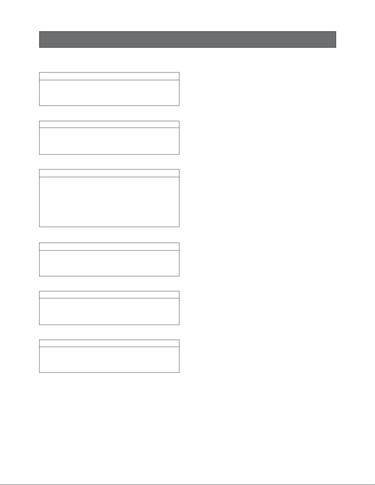
Secure the unit by 4 pieces of rack
mounting screws (M5 x 12) in the
accessories.
Where to install How to install
1. Install the unit on a rack.
Apply the screws in the accessories.
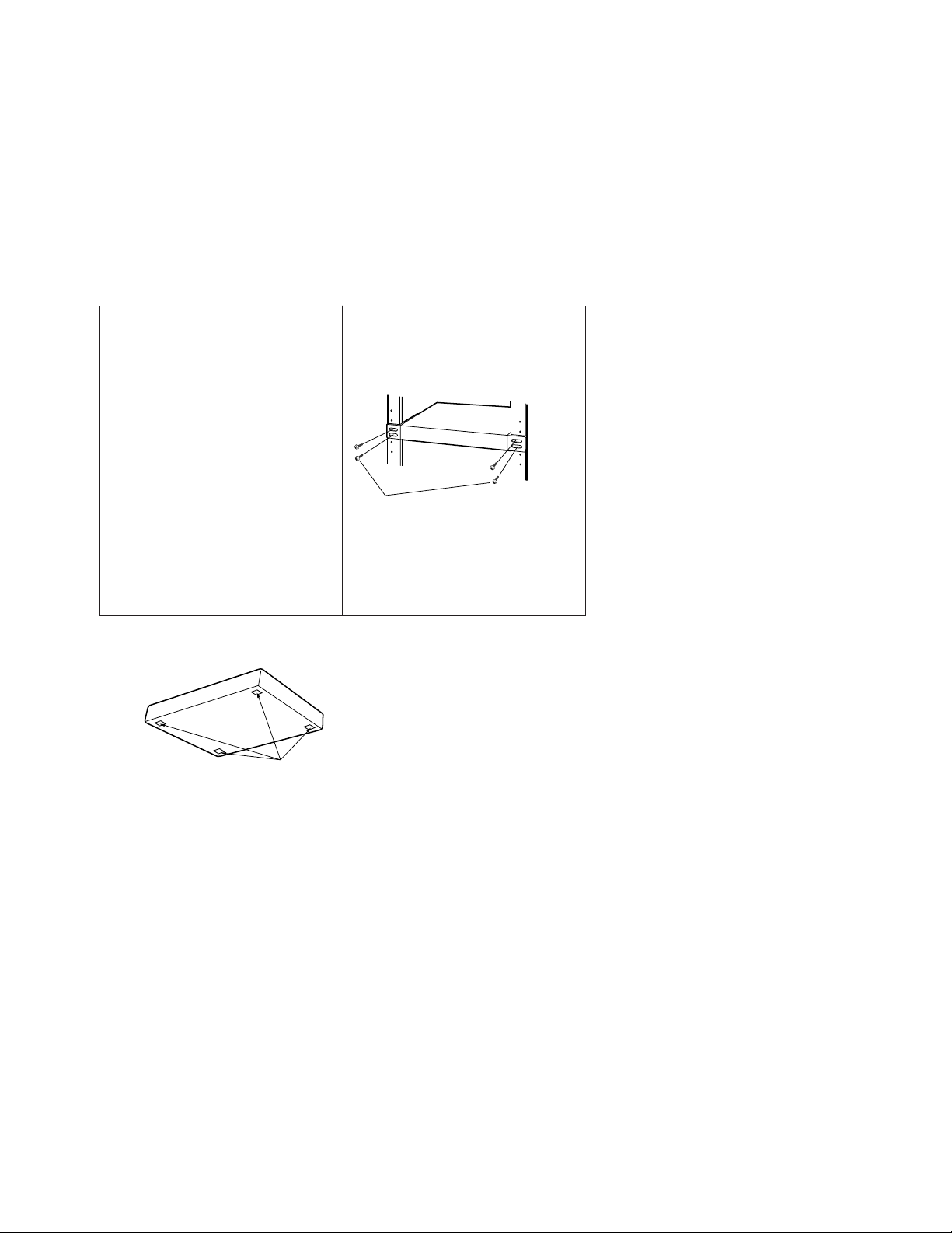
Note: Attach the four rubber feet if not installing the unit in a rack.
Cautions:
• When mounting this unit in a place where it is frequently subject to vibrations, secure its rear to the rack with reinforcing
angle steel (manufactured locally) or other materials.
• Keep the temperature in the rack below 45°C.
• Place this unit below heat-producing devices such as amplifiers if possible.
• If placing the unit below and above heat-producing devices such as amplifiers cannot be avoided, keep a distance of 1 U
or above the heat-producing devices.
• Use the rack mounting screws (nominal diameter: 5 x 12) supplied with the brackets if the mounting positions of the rack
are not tapped. If the screws are used at tapped positions of the rack, the original threads may be destroyed.
• The rack mounting screws in the accessories do not fit all types of racks. In that case, use the screws included with the
rack or buy your own screws.
■ Mounting into the Rack
● Rack
Use either one of the following racks for mounting the unit.
Standard: WU-RS71, capacity of 29 U (Panasonic)
Long: WU-RL76, capacity of 41 U (Panasonic)
EIA standard-compliant: depth 450 mm or more (other than Panasonic)
● Items to prepare
If you use a rack supplied by other than Panasonic, it may require four rack mounting screws (option) or four M5 x 12 screws.
(If you use a Panasonic rack, you can use the tapping screws supplied with the rack.)
Attach 4 rubber feet.
Page 13

13
■ Cable Information
The usable cable types, plugs, and connectors are the following.
Before connection, sure you are using the proper cables.
Screw (x3)
Spring washer
2
3
1
(COLD)
(HOT)
(GND)
HOT
GND
● Pin plug
● Tip-ring-sleeve (TRS) phone plug
● XLR connector (XLR3-12 type)
Caution:
No.2 pin of the XLR connector of this unit is hot. When connecting a device whose No.3 is hot, connect No.2 pin (No.3 pin)
of this unit to No.3 pin (No. 2 pin) of the device.
Notes:
• Be sure to use shielded wire for audio input/output lines.
• Use a cable of less than 10 m length for a high-impedance microphone. High-pass loss can occur if the cable capacity is
insufficient.
Use a cable less than 50 m when using a low-impedance microphone (150 Ω, 250 Ω or 600 Ω).
• Keep speaker lines away from input lines. Failure to do this may cause unstable operation and shaking.
HOT
GND
HOT
HOT(Tip)
COLD(Ring)
GND(Sleeve)
H (HOT)
2
1
3
GND
C (COLD)
Page 14

14
After connecting the external devices, do the following procedures:
• Mode setting
• Input signal assignment to the SUB OUTPUT jack
• Output signal assignment to the LINE IN jack, MULTI INPUT ST jacks, or MULTI INPUT MONO connector.
■ Unit Modes and Signal Flow
This unit has three modes. Set the suitable mode with DIP switch for the desired broadcasting system.
● Mode 1
Stereo or monaural amplification are applicable in Mode 1.
The stereo and mono input signals are mixed for output.
Stereo amplification
After the signals from stereo and mono input lines are mixed, they are output through the STEREO OUT jack toward one
zone.
Output jack(s) connecting the amplifier or speakers determine(s) the output line.
The mode is determined with Switch A and B of the DIP switches. (Refer to the next page.)
Signal Flow
To adjust the output levels
Mono and stereo outputs are individually adjustable.
In the case shown in the figure, the volume of microphones is adjusted with the MONO OUT knob and that of stereo source
devices is adjusted with the STEREO OUT knob.
SETUP PROCEDURES
Wireless microphone
Wireless
microphone
Diversity wireless receiver
Microphone
for a host
Microphone
on the platform
POWER
in the hall
Antenna for
wireless microphone
MONO
INPUT 1 to 4
MONO
1
2
6
6
4
4
100
28
100
4
28
28
3
6
100
4
6
4
28
100
28
Any output can be assigned.
Both mono and stereo inputs
are available.
CD TAPE
MD
STEREO
INPUT 1 to 4
STEREO
1
2
6
6
4
4
4
28
28
100
100
3
6
100
Video
sound
4
6
4
28
100
MULTI IN
(MONO/
STEREO)
ST
MONO
SUB
INPUT
MULTI IN
REAK
6
4
228
LINE IN
100
Power amplifier
STEREO
OUTPUT
STEREO OUT
MONO OUT
4
4
6
6
2
8
8
100
100
Speakers
Digital Multi Equalizer
Internal MIX
Audio Mixer WR-XS3
SUB OUT
6
4
28
100
Any mono and stereo
input can be assigned to
the SUB OUTPUT jack.
Page 15

15
Mono amplification
The signals from stereo or mono inputs are mixed and output through the MONO OUTPUT jack toward one zone.
Signal Flow
To adjust the output levels
Mono and stereo outputs are individually adjustable.
In the case shown in the figure, the volume of microphones is adjusted with the MONO OUT knob and that of stereo source
devices is adjusted with STEREO OUT knob.
DIP switch setting
Switches A and B are set to ON.
Wireless microphone
in the hall
Wireless
microphone
Diversity wireless receiver
Microphone
for a host
Microphone
on the platform
POWER
Antenna for
wireless microphone
MONO
INPUT 1 to 4
MONO
1
2
6
4
28
100
3
6
4
28
100
6
4
28
100
4
6
4
28
100
28
Any output can be assigned.
Both mono and stereo inputs
are available.
CD TAPE
STEREO
INPUT 1 to 4
1
6
4
28
100
MD
4
STEREO
2
6
100
Video
sound
3
6
4
28
100
4
6
4
28
100
MULTI IN
(MONO/
STEREO)
ST
MONO
SUB
INPUT
MULTI IN
REAK
6
4
228
LINE IN
100
Power amplifier
Digital Multi
Equalizer
STEREO OUT
4
6
2
8
100
MONO
OUTPUT
MONO OUT
4
Audio Mixer WR-XS3
6
SUB OUT
4
8
28
100
Ceiling speakers
Internal MIX
6
100
Any mono and stereo
input can be assigned to
the SUB OUTPUT jack.
ON
OFF
Switch B
Switch A
Page 16

16
● Mode 2
The stereo input signals are output through the STEREO OUTPUT jack, and mono input signals are output through MONO
OUTPUT jack.
BGM is output from the main speakers with stereo amplification, and microphone sounds are output from the ceiling speakers
with monaural amplification.
Signal Flow
To adjust the output levels
Mono and stereo outputs are individually adjustable.
In the case shown in the figure, the volume of microphones is adjusted with the MONO OUT knob and that of stereo source
devices is adjusted with the STEREO OUT knob.
DIP switch setting
Switch A is set to ON and Switch B is set to OFF.
Wireless microphone
in the hall
Wireless
microphone
Antenna for
wireless microphone
Any output can be assigned.
Speakers
Both mono and stereo inputs
are available.
Diversity wireless receiver
Microphone
for a host
Microphone
on the platform
POWER
1
6
4
28
100
MONO
INPUT 1 to 4
MONO
2
3
6
6
4
4
28
28
100
100
4
6
4
28
100
28
CD TAPE
MD
STEREO
INPUT 1 to 4
STEREO
1
2
6
4
28
100
3
4
28
6
4
100
sound
6
100
Video
4
6
4
28
100
MULTI IN
(MONO/
STEREO)
ST
MONO
SUB
INPUT
MULTI IN
REAK
6
4
228
LINE IN
100
Power amplifier
Digital Multi
Equalizer
STEREO
OUTPUT
STEREO OUT
MONO OUT
4
4
6
2
8
100
MONO
OUTPUT
Audio Mixer WR-XS3
6
SUB OUT
6
4
8
28
100
100
Any mono and stereo
input can be assigned to
the SUB OUTPUT jack.
Ceiling speakers
ON
OFF
Switch B
Switch A
Page 17

17
● Mode 3
The signals from stereo or mono input lines are separately output through the STEREO OUTPUT, MONO OUTPUT and SUB
OUTPUT jack. For example, this connection is used for zone amplification in a shop.
• The signals from the MONO INPUT 1 and 2 connectors are output through the STEREO OUTPUT and MONO OUTPUT
jacks. (Input for all-call broadcasting in any zone)
• The signals from the MONO INPUT 3 connector are output through the STEREO OUTPUT jack (Zone 1) and the signals
from MONO INPUT 4 connector are output through the MONO OUTPUT jack (Zone 2). (Input for broadcasting in each
zone)
• The signals from the STEREO INPUT 1 to 4 jacks are output through the STEREO OUTPUT (Zone 1) and MONO OUTPUT
(Zone 2) jack.
• Amplification in other areas is possible by assigning another BGM to the SUB OUTPUT jack and mixing with all-call broadcasting.
• The signals from the MULTI INPUT ST jack or MULTI INPUT MONO connector are output to the STEREO OUTPUT, MONO
OUTPUT and SUB OUTPUT jacks.*
*The output line is assigned with the assign button setting. (Refer to p. 19.)
To adjust the output levels
Requires setting of an internal switch.
In the case shown in the figure, the volume of Zone 1 is adjusted with the STEREO OUT knob ,and that of Zone 2 is adjusted with the MONO OUT knob.
To output the mono mix signal (the same signal
through the STEREO OUTPUT jack)
The internal switch setting is necessary.
Refer to a service manual procurable in your area.
DIP switch setting
Switches A and B are set to OFF.
Wireless microphone
Wireless
microphone
Wireless
microphone
Diversity wireless receiver
in the hall
Antenna for
wireless microphone
Mono output is
also available
in Zone 1.
(Switch inside)
Speakers
Zone 2
4
6
4
28
100
28
CD TAPE
MD
STEREO
INPUT 1 to 4
STEREO
1
2
6
4
28
100
3
4
28
6
4
100
Video
sound
6
28
100
Power
amplifier
Digital Multi
Equalizer
MONO
MULTI IN
4
228
SUB
6
100
Zone 1 Zone 2
STEREO OUT
4
INPUT
REAK
LINE IN
6
8
100
SUB OUT
6
4
2
8
28
100
100
Audio Mixer WR-XS3
MONO OUT
4
6
ST
4
6
4
100
Any mono and stereo input
can be assigned to the SUB
OUTPUT jack as Zone 3
Microphone
for a host
Microphone
on the platform
POWER
MONO
INPUT 1 to 4
1
2
6
4
4
28
28
100
MONO
1 to 2
(Zone 1 and 2)
MONO
6
100
3
6
4
28
100
MONO3
(Zone 1)
MONO4 (Zone 2)
ON
OFF
Switch B
Switch A
Page 18

18
■ Input Line Setting for SUB OUTPUT
The SUB OUTPUT jack at the rear panel can output any signal from the STEREO INPUT 1 to 4 jacks or MONO INPUT 1 to 4
connectors. The output setting is determined with the DIP switch setting.
The input signal from the LINE IN jack, MULTI INPUT ST jacks or MULTI INPUT MONO is also assignable to the SUB OUTPUT
jack. The output setting is determined with the assign button setting at the front panel. Refer to p. 19.
● DIP switch setting
The input line is assigned to the SUB OUTPUT jack by setting Switches MONO 1 to 4 and STEREO 1 to 4.
When all DIP switches are set to ON, the associated input signal is assigned to the SUB OUTPUT jack.
More than one input line is selectable.
The figure shows an example that assigns the MONO INPUT 3 connector, STEREO INPUT 2 jack, and STEREO INPUT 4 jack
to the SUB OUTPUT jack.
Any output can be
assigned. Both mono and
stereo inputs are available.
ST
MONO
SUB
STEREO OUT
4
POWER
1
6
4
28
100
MONO
2
6
4
28
100
3
6
4
28
100
4
6
4
28
100
1
6
4
28
100
STEREO
2
6
4
28
100
3
6
4
28
100
4
4
28
INPUT
MULTI IN
REAK
6
6
4
228
LINE IN
100
100
Audio Mixer WR-XS3
MONO OUT
4
6
6
8
100
SUB OUT
6
4
2
8
28
100
100
ON
OFF
STEREO
INPUT SELECT
MONO
12341234
Page 19

19
■ Output Line Setting for MULTI IN/LINE IN
The signal from the MULTI IN ST jacks and MULTI IN MONO connector at the rear panel can be output through any of the
STEREO OUT, MONO OUT and SUB OUTPUT jacks The output connector is assigned with the assign switches at the front
panel.
The LINE IN jack at the front panel is also usable as a multiple input connector.
●
Assign button setting
The output line is assigned to the MULTI INPUT ST jacks, the MULTI INPUT
MONO connector or the LINE IN jack with an assign button setting.
Press the ST, MONO or SUB button at the front panel.
The details of button setting are described in the tables below.
Suitable levels for the MULTI IN knob
Jack
Assign button setting
MULTI INPUT MONO
MONO or SUB
MONO is recommended when a microphone is connected to this
jack in Mode 1 or 2. The level is adjustable together with other
microphones by the MONO OUT knob.
MULTI INPUT STEREO
ST
When an external device is connected to this jack in Mode 1 or 2,
the level is adjustable together with other devices by STEREO OUT
knob.
Jack
Device Level
MULTI IN STEREO CD/MD player 5 to 8
Cassette player and cable
broadcasting
8 to 9
MULTI IN MONO Microphone 8 to 10
LINE IN Portable MD/CD player 8 to 9
PC sound output 7 to 9
Any output can be assigned.
Both mono and stereo inputs are available.
(Line input at the front supported.)
ST
MONO
SUB
POWER
1
6
4
28
100
MONO
2
6
4
28
100
3
6
4
28
100
4
6
4
28
100
1
6
4
28
100
STEREO
2
6
4
28
100
3
6
4
28
100
4
4
28
INPUT
MULTI IN
REAK
6
6
4
228
LINE IN
100
100
STEREO OUT
4
Audio Mixer WR-XS3
MONO OUT
4
6
6
2
8
8
100
100
Assign buttons
ST
MONO
MULTI IN
4
6
4
4
28
228
100
SUB OUT
6
4
28
100
SUB
INPUT
REAK
6
LINE IN
100
STEREO OUT
4
6
8
100
SUB OUT
6
4
2
8
28
100
100
Audio Mixer WR-XS3
MONO OUT
4
6
Page 20

20
When using the MULTI INPUT ST jacks (or MONO connector) and LINE IN jack at the same time
In this case, the signal from the MULTI INPUT ST jacks will not be output.
The signal is mixed inside the unit and output through the assigned output connector.
Notes:
• Do not use the MULTI INPUT ST jacks and MULTI INPUT MONO connector at the same time. The MULTI IN knob is not
adjustable, as each multiple input level is different.
• Mono and stereo input signals are mixed inside the unit. When you do not want to have the mono input mixed, you need to
change the internal switch setting.
Refer to a service manual procurable in your area.
To adjust the output levels
The input signal from the MULTI INPUT ST jacks (or MULTI INPUT MONO connector) is mixed by the unit, then it is output
through the output line.
The output line is selectable with the assign button setting at the front panel.
• Adjust the output level with the STEREO OUT knob when the STEREO OUTPUT jack is assigned to the MULTI INPUT ST
jacks (or MULTI INPUT MONO connector).
• Adjust the output level with the MONO OUT knob when the MONO OUTPUT jack is assigned to the MULTI INPUT ST jacks
(or MULTI INPUT MONO connector).
• Adjust the output level with the SUB OUT knob when the SUB OUTPUT jack is assigned to the MULTI INPUT ST jacks (or
MULTI INPUT MONO connector).
Page 21

21
■ Example 1: Home Party (Mode 1)
•Set the DIP switches to Mode 1. (Refer to p. 15.).
• Mic 1 to 4 (MONO IN 1 to 4), Key (ST IN 1), Bass AMP (ST IN 2) and DVD/CD/MD (ST IN 3 and 4) are mixed to be output to
the main speakers (ST OUT L/R).
• The power amplifier adjusts the output level of sound sources you want to confirm. These are then output to the foldback
loudspeakers (SUB OUT).
• Recording is available through REC OUT when connecting a tape recorder or MD recorder to ST IN 3 and 4.
CONNECTION EXAMPLES
ON
OFF
4
28
100
1
6
4
28
100
2
6
4
28
100
3
6
4
28
100
4
6
MONO
POWER
4
28
100
1
6
4
28
100
2
6
4
28
100
3
6
4
28
100
4
6
4
4
228
8
100
100
6
6
ST
MULTI IN
4
28
100
6
SUB OUT
STEREO
MONO
STEREO OUT
INPUT
REAK
LINE IN
SUB
4
2
8
100
6
MONO OUT
Audio Mixer WR-XS3
DVD/CD
MD
Bass AMP
TAPE(REC)
AG
(Mic 4)
WR-XS3
BTL Drive
Vo
(Mic 1)
Cho
(Mic 2)
Cho
(Mic 3)
Key
DI out
Power amplifier Power amplifierPower amplifier
Equalizer
DIP switch setting
Main speakers
Foldback loudspeakers
Power control unit
Unit mode : 1
Sub output: MONO IN 1 to 4
and STEREO 1, 2
MONO IN 1
SUB OUT
ST OUT R
ST OUT L
MONO IN 2
MONO IN 3
MONO IN 4
ST IN 1
ST IN 2
REC OUT
ST IN
3 and 4
Page 22

22
■ Example 2: Presentation Room (Mode 2)
MONO IN 1
REC OUT
MONO IN 2
MONO IN
3 to 4
ST IN
1 to 4
LINE IN
SUB OUT
MONO OUT
ST OUT L
ST OUT R
ON
OFF
4
28
100
1
6
4
28
100
2
6
4
28
100
3
6
4
28
100
4
6
MONO
POWER
4
28
100
1
6
4
28
100
2
6
4
28
100
3
6
4
28
100
4
6
4
4
228
8
100
100
6
6
ST
MULTI IN
4
28
100
6
SUB OUT
STEREO
MONO
STEREO OUT
INPUT
REAK
LINE IN
SUB
4
2
8
100
6
MONO OUT
Audio Mixer WR-XS3
Ceiling speakers
DVD/CD
MD
TAPE
VTR
TAPE(REC)
WR-XS3
Projector
Note PC
Portable MD
Antenna for
wireless microphone
Wireless
microphone
Mic 1 Mic 2
Diversity wireless receiver
Howling suppressor
[Your sources]
Main speakers
AV switcher
DIP switch setting
Foldback powered loudspeaker
(For Mic 1 and 2)
Power control unit
Equaliser
Power amplifier
Power amplifier
Unit mode: 2
Sub output:MONO IN 1
and 2
•Set the DIP switches to Mode 2. (Refer to p. 16.).
• This connection raises the howling margin. BGM (ST IN) is output through ST OUT L/R to the main speakers.
Sounds from microphones (MONO IN 1 and 2) and wireless microphones (MONO IN 3 and 4) are output to ceiling speakers (MONO OUT).
• Your presentation sources can be input from the front panel's LINE IN to be mixed through an AV switcher (ST IN 1 to 4).
• Sounds from Mic 1 and 2 (MONO IN 1 and 2) can be output to the foldback loudspeaker (SUB OUT).
Page 23

23
■ Example 3: Shop (Mode 3)
ST OUT L
MONO IN 1
MONO IN 2
MONO IN 3
MONO IN 4
MULTI IN ST
MONO OUT
SUB OUT
ST IN
1 to 4
ON
OFF
4
28
100
1
6
4
28
100
2
6
4
28
100
3
6
4
28
100
4
6
MONO
POWER
4
28
100
1
6
4
28
100
2
6
4
28
100
3
6
4
28
100
4
6
4
4
228
8
100
100
6
6
ST
MULTI IN
4
28
100
6
SUB OUT
STEREO
MONO
STEREO OUT
INPUT
REAK
LINE IN
SUB
4
2
8
100
6
MONO OUT
Audio Mixer WR-XS3
CD
TAPE
WR-XS3
Cable broadcasting (BGM)
Shopping zone 1
main speakers
Shopping zone 2
main speakers
Resting place (zone 3)
main speakers
All-call Shop 1
microphone
Shop 2
microphone
Power control unit
Equaliser
DIP switch setting
When connecting SW BOX
to MONO 2 or 4, announcement in Shopping zones 1,
2 and all-call can be
performed with one microphone.
Unit mode: 3
SUB OUT: Cable broadcasting,
Mic 1, Mic 2
Internal switch: ON
Power amplifier Power amplifier Power amplifier
Mic 1 Mic 2
•Set the DIP switches to Mode 3 (refer to p. 17) to form a three-zone amplification system.
• The amplification system is composed of Shopping zones 1, 2 and Resting place (Zone 3).
• The cable broadcasting connects the MULTI IN ST jacks and output to the main speakers (SUB OUT) in the resting place.
Another BGM (CD or TAPE) connects ST IN 1 to 4 and output to the main speakers in Shopping zone 1 and 2 (ST OUT L
and MONO OUT).
• All-call amplification is also available in the resting place. Mic 1 or 2 (MONO IN 1 and 2) is output to the main speakers
(SUB OUT).
Page 24

24
When you connect a cassette tape recorder or MD recorder to record the broadcasting, confirm the following:
■ Notice about Recorder Connections
Howling can occur depending on the connection form or connected devices. Connect the recording devices either of the following ways:
● When Using a Recording-only and a
Playback-only Decks
The unit 's REC OUT will be used for the recording output
line.
• Connect the unit's REC OUT with the recording deck's
REC IN.
• Connect the unit' s STEREO INPUT or MULTI INPUT ST
jacks with the playback deck's stereo output connector.
● When Recording and Playing Back
with One Deck
The unit' s SUB OUTPUT jack will be used for the recording
output line.
•Set the DIP switch of the assigned input line to ON.
• Connect the unit' s SUB OUTPUT and the recorder's
recording output connector with a recommended type
of cable. (Refer to p. 13 for details on cable information.)
• Connect the unit' s STEREO INPUT, MULTI INPUT ST or
LINE IN jack(s) and the output connector of the playback deck.
Note: This connection implements monaural recording, as stereo input signals are mono mixed to be output through SUB
OUTPUT jack.
■ Using a Recording-only and a Playback-only Decks
A recording-only and a playback-only decks are used.
1. Connect the playback-only deck to the STEREO INPUT 1 to 4 jacks or the MULTI INPUT ST jack.
2. Connect the recording-only deck to the REC OUT jack.
RECORDER CONNECTIONS
You want to play back and
record the broadcasting on
the cassette tape or MD.
You do not use SUB
OUTPUT jack.
NO
Use a recording deck and
playback deck.
YES
Mono recording is OK.
NO
YES
You can record and play
back with one deck.
Use a recording deck and
playback deck.
REC
MODE
SELECT
ON
OFF
1
2
3
MODE
A
43214321
B
STEREO
INPUT
REC OUT
OFF ON
3 4
ST AUTO MUTE
MONO
SELECT
MONO
SUB
OUTPUT +4dB 10kΩ
PIN CONNECTION
No. 1: GND
No. 2: HOT
No. 3: COLD
STEREO
L
LR
R
–10dBV 10kΩ +4dB 10kΩ –10dBV 10kΩ
REC OUT
Recording only deck
PLAY
Playback-only deck
STEREO INPUT 1 to 4
MONOST
L
R
–45dB 10kΩ
MULTI INPUTSUB IN
234
L
R
MONO INPUT –60dB to –10dB 10kΩINPUT –10dBV 10kΩSTEREO
3 4
ST AUTO MUTE
0dB is referenced to 0.775Vrms
12341
SIGNAL
AC IN
GND
Ser No.
Page 25

25
■ Recording and Playback with One Deck
To record and play back a broadcast with one deck, connect the SUB OUTPUT jack to cut the feedback.
Then set the DIP switch associated with the MULTI INPUT ST jacks to OFF.
Note: Use the cable shown in the figure to connect the unit SUB OUT and the deck's REC OUT.
To output either mono or stereo signal through REC OUT
The stereo and mono recording input signals are usually mixed through the REC OUT jack.
The internal switch setting is necessary if you want to output either of them.
Refer to a service manual procurable in your area.
REC
PLAY
Recording and playback deck
ON
OFF
MODE
A
43214321
B
1
STEREO
2
SELECT
INPUT
3
MODE
SELECT
SUB OUTPUT
PIN CONNECTION
No. 1: GND
OFF ON
No. 2: HOT
No. 3: COLD
3 4
ST AUTO MUTE
MONO
STEREO
MONO
SUB
OUTPUT +4dB 10kΩ
L
LR
R
–10dBV 10kΩ +4dB 10kΩ –10dBV 10kΩ
REC OUT
L
R
–45dB 10kΩ
MULTI INPUTSUB IN
STEREO INPUT 1 to 4
MONOST
234
L
R
MONO INPUT –60dB to –10dB 10kΩINPUT –10dBV 10kΩSTEREO
3 4
ST AUTO MUTE
0dB is referenced to 0.775Vrms
12341
Ser No.
SIGNAL
AC IN
GND
RCA pin plug
Tip-ring-sleeve (TRS)
The unit's
phone plug (STEREO)
SUB OUT
The deck's
REC IN
Page 26

26
STICKING LABELS
After the connection and settings, stick the supplied labels on the front panel of the unit.
The labels indicate the following:
• Name and level setting of each knob
• Mode setting
• Input line assigned to the SUB OUTPUT jack
■ Label
■ Where to Stick Labels
Stick the corresponding label in the corresponding position as shown in the figure.
Each label will be used as follows:
For MONO INPUT, For STEREO INPUT: for input line indication
For OUTPUT: for output line indication
MODE SETTING label: for setting mode indication
Marker for volume setting label: for volume level indication
■ For MONO INPUT
MIC1 MIC2 MIC3 MIC4 MIC5
Wireless1 Wireless2 Wireless3 Wireless4 Wireless5
■ For STEREO INPUT
CD MD TAPE DVD VTR LD
CD1 MD1 TAPE1 DVD1 VTR1 LD1
CD2 MD2 TAPE2 DVD2 VTR2 LD2
DAT Video
DAT1 Radio
DAT2 BGM
■ For OUTPUT
MAIN REAR
MONITOR
CEILING
REC
STEREO
MIC BGM
■ MODE SETTING ■
MODE1-1
MONO 2134ST234 ST MONOSUB OUT
1
MODE1-2
MODE2
MODE3
MONO 2134ST234 ST MONO1
MONO 2134ST234 ST MONO1
MONO 2134ST234 ST MONO1
12341234
MONO
STEREO
Marker for volume setting
MODE SETTING label
ST
MONO
MULTI IN
4
6
4
228
100
POWER
MODE1-1
MONO 2134ST 234 ST MONO1
1
6
4
28
100
MONO
2
6
4
28
28
100
3
4
6
28
100
4
4
6
100
1
6
4
28
28
100
For STEREO INPUT label For OUTPUT labelFor MONO INPUT label
4
STEREO
2
6
100
3
6
4
28
28
100
4
Marker for volume setting label
SUB
6
100
INPUT
REAK
LINE IN
STEREO OUT
4
6
8
100
2
MONO OUT
4
Audio Mixer WR-XS3
6
SUB OUT
4
8
28
100
100
6
SUB OUT
12341234
MONO
STEREO
MODE SETTING label
Page 27

27
■ Indication of Input Line Assigned to SUB OUT
Draw a line between SUB OUT and the assigned input connector, or black out the square.
The assigned input line will be identifiable.
Draw a line or black
out to identify the
assigned input line.
SUB OUT
1234 123
MONO
STEREO
4
Page 28

28
ATTACHING/DET ACHING THE ACRYLIC COVER
The input levels need to be adjusted before using the unit.
After the adjustments, attaching the supplied acrylic cover
with mounting spacers and screws can prevent the wrong
operation of input levels.
The acrylic cover protects the different range of input level
controls depending on the direction in which it is installed.
● The MULTI IN knob is adjustable.
● The MULTI IN knob is not adjustable.
Acrylic cover
mounting screws (M3 x 6)
Acrylic cover
mounting spacers x 2
Acrylic cover
ST
MONO
SUB
MONO
1
2
3
6
100
6
4
28
100
4
4
28
100
6
4
POWER
28
100
4
28
6
28
STEREO
1
2
3
6
6
100
4
28
100
6
4
28
100
28
4
INPUT
MULTI IN
4
REAK
6
6
4
4
228
LINE IN
100
100
ST
MONO
SUB
MONO
1
2
3
6
100
6
4
28
100
4
4
28
100
6
4
POWER
28
100
4
28
6
28
STEREO
1
2
3
6
6
100
4
28
100
6
4
28
100
28
4
INPUT
MULTI IN
4
REAK
6
6
4
4
228
LINE IN
100
100
STEREO OUT
4
STEREO OUT
4
Audio Mixer WR-XS3
MONO OUT
6
4
6
SUB OUT
6
4
2
8
8
28
2
MONO OUT
4
100
Audio Mixer WR-XS3
6
SUB OUT
4
8
28
100
100
6
100
100
6
8
100
Page 29

29
■ Basic Operation
This section describes basic operation. All setup items and connections must be completed in advance.
The switches located under the acrylic cover normally do not need to be accessed for operation. Access is required only to
the switches outside the acrylic cover.
Confirm that the connections of all the devices and all set modes and input/output levels are correct.
Note: Set the STEREO OUT, MONO OUT and SUB OUT knob to “0” before operation.
1. Press the power switch on the front.
This turns on the unit and the power indicator.
2. Speak into a microphone or play back an external device such as a CD player.
3. Increase the level of the STEREO OUT, MONO OUT or SUB OUT knob gradually from 0.
Sound comes from the speakers.
"7" is the desired volume level.
4. Turn off the power amplifiers.
5. Press the power switch of the unit. The unit and the power indicator turn off.
6. Turn off the external devices.
Notes:
• In Mode 1 (refer to p. 21) or 2 (refer to p. 22), the volume of BGM is adjustable with the STEREO OUT knob, and that of
microphones is adjustable with the MONO OUT knob.
• In Mode 3 (refer to p. 23), the volume of Zone 1 is adjustable with the STEREO OUT knob, and that of Zone 2 is adjustable
with the MONO OUT knob.
• When one of the STEREO INPUT 1 to 4 jacks or MONO INPUT 1 to 4 connectors is assigned to the SUB OUTPUT jack, the
output level is adjustable with the SUB OUT knob.
OPERATIONS
ST
MONO
POWER
1
6
4
28
28
100
4
2
6
100
MONO
3
4
28
6
28
100
4
4
6
100
1
6
4
28
28
100
4
STEREO
2
6
100
3
6
4
28
100
4
6
4
28
100
MULTI IN
4
228
SUB
6
100
INPUT
REAK
LINE IN
STEREO OUT
4
Knobs for output level adjustments
6
8
100
2
MONO OUT
4
Audio Mixer WR-XS3
6
SUB OUT
4
8
28
100
100
6
ST
MONO
POWER
1
6
4
28
28
100
4
2
6
100
MONO
3
4
28
6
28
100
4
4
6
100
1
6
4
28
28
100
4
STEREO
2
6
100
3
6
4
28
100
4
6
4
28
100
MULTI IN
4
228
SUB
6
100
INPUT
REAK
LINE IN
STEREO OUT
4
6
8
100
2
MONO OUT
4
Audio Mixer WR-XS3
6
SUB OUT
4
8
28
100
100
6
Knobs for output level adjustments
Page 30

30
■ Input Level Adjustment
This section describes how to adjust input levels.
The figure describes an example.
• Mode 1
• The microphone is connected to the MONO INPUT 1 connector and the CD player is connected to the STEREO INPUT 1
jack.
• The input signal of the MONO INPUT 1 connector and the STEREO INPUT 1 jack are mixed inside the unit, and amplified
through the STEREO OUTPUT jack.
Note: Detach the acrylic cover before the level adjustment. (Refer to p. 28 ATTACHING/DETACHING THE ACRYLIC COVER.)
1. Decrease the attenuator level to ∞.
2. Increase the level of the STEREO OUT and MONO OUT
knobs to 7.
3. Connect a CD player to the STEREO INPUT 1 jacks to
play back a CD.
4. Increase the level of the STEREO 1 knob gradually from
0.
5. Adjust the attenuator to the proper level.
6. Connect a microphone to the MONO INPUT 1 connector and speak into it.
7. Increase the level of MONO 1 knob while speaking into
the microphone.
Refer to the knob's figure in p. 8 for the desired level
setting.
Notes:
• Set the STEREO 1 knob to the level at which the input
peak indicator does not light up.
• Set the output level of the diversity wireless receiver to
– 20 dB and that of the MONO 1 knob when using a
wireless microphone. 3 to 5 is the desired level.
• Adjust the attenuator level if the microphone sound volume is too low even when the MONO 1 knob is set to 10
or if it is too high even when the MONO 1 knob is set to
1.
• The desired levels of the STEREO 1 knob are as follows.
CD/MD player: 5 to 7
Cassette player or cable broadcasting: 8 to 9
• The desired levels of the MONO 1 knob are as follows.
Big voice: 4 to 8
Small voice: 8 to 10
T
Speaker
Microphone
CD
Power amplifier
Equalizer
STEREO
OUTPUT
POWER
MONO
INPUT 1
1
6
4
28
100
MONO
2
6
4
28
100
4
28
3
6
100
4
6
4
28
100
STEREO
INPUT 1
1
6
4
28
28
100
4
2
6
100
STEREO
4
28
3
6
100
4
6
4
28
100
ST
MONO
MULTI IN
4
228
Internal MIX
SUB
STEREO OUT
4
INPUT
6
LINE IN
100
6
REAK
100
8
2
MONO OUT
4
Audio Mixer WR-XS3
6
SUB OUT
4
8
28
100
6
100
ST
MONO
MULTI IN
4
228
SUB
6
100
LINE IN
STEREO OUT
4
INPUT
REAK
6
8
100
Knobs for output level adjustments
(STEREO OUT/MONO OUT)
2
MONO OUT
4
Audio Mixer WR-XS3
6
SUB OUT
6
4
8
28
100
100
POWER
1
4
28
Knob for input level adjustment
6
28
100
2
4
MONO
6
28
100
4
3
6
100
4
6
4
28
28
100
4
1
6
100
4
28
(MONO1)
ST
MONO
SUB
MONO
2
6
4
28
28
100
3
4
6
28
100
4
4
6
100
1
6
4
28
28
100
2
4
STEREO
6
28
100
4
3
6
100
4
6
4
28
100
INPUT
MULTI IN
REAK
6
4
28
LINE IN
100
Knob for input level adjustment
(STEREO 1)
S
2
6
100
Page 31

31
■
Using CD/MD Player through LINE IN
This section describes amplification when a CD player or
MD player, etc. is connected to the LINE IN jack at the front
panel.
1. Set the LINE IN jack's output level knob to 0.
2. Connect the CD/MD player etc. to the LINE IN jack.
3. Press the ST, MONO or SUB button to assign an output
line to the LINE IN jack.
4. Press the POWER switch to turn on the power.
5. Play back an external device such as a CD/MD player,
etc.
6. Increase the input level with MULTI IN knob gradually
from 0. When the INPUT PEAK indicator lights up,
decrease the level, as it has reached -3 dB over the clip
level.
4
4
228
8
100
100
6
6
ST
MULTI IN
4
28
100
6
SUB OUT
MONO
STEREO OUT
INPUT
REAK
LINE IN
SUB
4
2
8
100
6
MONO OUT
Audio Mixer WR-XS3
Knobs for output level adjustments
2
7. Adjust the output level with the knob (ST, MONO or
SUB OUT) of the assigned output line.
Notes:
• Set the output level of the CD/MD player to the maximum.
• The desired levels of the output line are as follows.
Portable CD/MD player: 8 to 9
PC sound output: 8 to 9
4
4
228
8
100
100
6
6
ST
MULTI IN
4
28
100
6
SUB OUT
MONO
STEREO OUT
INPUT
REAK
LINE IN
SUB
4
2
8
100
6
MONO OUT
Audio Mixer WR-XS3
Knobs for output level adjustments
ST
MONO
MULTI IN
4
228
SUB
6
100
INPUT
REAK
LINE IN
STEREO OUT
4
6
8
100
2
MONO OUT
4
Audio Mixer WR-XS3
6
SUB OUT
4
8
28
100
100
6
ST
MONO
MULTI IN
4
228
SUB
6
100
INPUT
REAK
LINE IN
STEREO OUT
4
6
8
100
2
MONO OUT
4
Audio Mixer WR-XS3
6
SUB OUT
6
4
8
28
100
100
Knobs for output level adjustments
ST
MONO
MULTI IN
4
228
SUB
6
100
INPUT
REAK
LINE IN
STEREO OUT
4
6
8
100
2
MONO OUT
4
Audio Mixer WR-XS3
6
SUB OUT
4
8
28
100
100
6
POWER
1
4
28
6
28
100
4
MONO
2
6
100
3
6
4
28
28
100
4
4
6
100
1
6
4
28
100
ST
MONO
4
6
4
28
100
MULTI IN
4
228
SUB
6
100
INPUT
REAK
LINE IN
STEREO OUT
4
6
8
100
2
MONO OUT
4
Audio Mixer WR-XS3
6
SUB OUT
6
4
8
28
100
100
4
2
0
Page 32

32
BLOCK DIAGRAM
HPF
SENS
SENS
MONO 1
MULTI IN
MONO
MULTI IN
ST
LINE IN
(FRONT PANEL)
HPF
MONO 2
HPF
MONO 3
HPF
MONO 4
ST 1
MUTE SENSE
REAR PANEL SW
ST 2
ST 3
ST 4
SUB IN
Mute
STEREO
MONO
SUB
Assign SW
(FRONT PANEL)
L
STEREO MONO SUB
R
ST/MONO
Inner SW
L
R
REC OUT
STEREO OUT
MONO OUT
SUB OUT
PEAK LED
MONO 1
about MODE
MODE SELECT A MODE SELECT B
MODE 1 ON ON
MODE 2 ON OFF
MODE 3 OFF OFF
ON
MONO 2
MONO 3
MONO 4
ST 1
ST 2
ST 3
ST 4
MODE SELECT B
MODE SELECT A
MODE SELECT
INPUT SELECT
for SUB OUT
MIXING POINT
Electric Switch
MULTI IN MONO
Inner SW
Page 33

33
HPF
SENS
SENS
MONO 1
MULTI IN
MONO
MULTI IN
ST
LINE IN
(FRONT PANEL)
HPF
MONO 2
HPF
MONO 3
HPF
MONO 4
ST 1
MUTE SENSE
REAR PANEL SW
ST 2
ST 3
ST 4
SUB IN
Mute
STEREO
MONO
SUB
Assign SW
(FRONT PANEL)
L
STEREO MONO SUB
R
ST/MONO
Inner SW
L
R
REC OUT
STEREO OUT
MONO OUT
SUB OUT
PEAK LED
MONO 1
about MODE
MODE SELECT A MODE SELECT B
MODE 1 ON ON
ON
MONO 2
MONO 3
MONO 4
ST 1
ST 2
ST 3
ST 4
MODE SELECT B
MODE SELECT A
MODE SELECT
INPUT SELECT
for SUB OUT
MIXING POINT
Electric Switch
MULTI IN MONO
Inner SW
■ MODE1
Page 34

34
■ MODE 2
HPF
SENS
SENS
MONO 1
MULTI IN
MONO
MULTI IN
ST
LINE IN
(FRONT PANEL)
HPF
MONO 2
HPF
MONO 3
HPF
MONO 4
ST 1
MUTE SENSE
REAR PANEL SW
ST 2
ST 3
ST 4
SUB IN
Mute
STEREO
MONO
SUB
Assign SW
(FRONT PANEL)
L
STEREO MONO SUB
R
ST/MONO
Inner SW
L
R
REC OUT
STEREO OUT
MONO OUT
SUB OUT
PEAK LED
MONO 1
about MODE
MODE SELECT A MODE SELECT B
MODE 2 ON OFF
ON
MONO 2
MONO 3
MONO 4
ST 1
ST 2
ST 3
ST 4
MODE SELECT B
MODE SELECT A
MODE SELECT
INPUT SELECT
for SUB OUT
MIXING POINT
Electric Switch
MULTI IN MONO
Inner SW
Page 35

35
■ MODE 3
HPF
SENS
SENS
MONO 1
MULTI IN
MONO
MULTI IN
ST
LINE IN
(FRONT PANEL)
HPF
MONO 2
HPF
MONO 3
HPF
MONO 4
ST 1
MUTE SENSE
REAR PANEL SW
ST 2
ST 3
ST 4
SUB IN
Mute
STEREO
MONO
SUB
Assign SW
(FRONT PANEL)
L
STEREO MONO SUB
R
ST/MONO
Inner SW
L
R
REC OUT
STEREO OUT
MONO OUT
SUB OUT
PEAK LED
MONO 1
about MODE
MODE SELECT A MODE SELECT B
MODE 3 OFF OFF
ON
MONO 2
MONO 3
MONO 4
ST 1
ST 2
ST 3
ST 4
MODE SELECT B
MODE SELECT A
MODE SELECT
INPUT SELECT
for SUB OUT
MIXING POINT
Electric Switch
MULTI IN MONO
Inner SW
Page 36

36
LEVEL DIAGRAM
+30
+20
+10
0
–10
–20
–30
–40
–50
–60
–70
–80
–90
–100
–110
–120
–130
(dBu)
+30
+20
+10
–10
–20
–30
–40
–50
–60
–70
–80
–90
–100
–110
–120
–130
(dBu)
ST "10"
MONO "2"
MONO "10"
MONO "2"
ST "10"
MONO "10"
MULTI IN
(MONO) "10"
CLIP LEVEL
+24
+4
–61
–86
–94
Output residual noise (TYP)
MONO "10"
Setting output noise (TYP)
MONO "2"
ST "10"
Setting output noise
(TYP)
HA1
(+38.9 to +2.4 to –3.6) (+9.6) (+11.9) (0)
(0)
(+6) (–2.5)
(–6)
HA2 BA BA
(+6)
BTL
Σ Σ Σ
ST, MONO OUT
+4 dB
HA1
(+27.6) (+9.6)
(0)
(+3.5)
(–6)
HA2
BA
(+6)
BTL
SUB OUT
+4 dB
LA
(+8.2)
(0)
(0)
(0)
(–8.2)
(–0.3)
BA
BA
REC OUT
–10 dBV (–7.8dBu)
LA
(+8.2)
(0)
(0)
(0)
BA BA
(0)
Σ
SUB IN
+4 dBu
–10 dBV
(–7.8 dBu)
ST IN
–10 dBV
(–7.8 dBu)
MULTI IN
–45 dBu
MONO IN
–60 dBu
to –10 dBu
Page 37

37
Trouble
Check item Remedy
Power does not turn on.
No sound is heard from the
speakers connected to SUB
OUTPUT.
The power cord insulation is
damaged.
The power cord, plug and
connectors get hot during
the use.
Is the power cord connected between the
inlet socket of this unit and AC receptacle?
Is the DIP switch of the assigned input line
set to OFF?
Connect the power cord between the
power socket of this unit and AC receptacle.
Set the DIP switch of the assigned input
line to ON.
(Refer to p. 18)
No sound is heard from the
device connected to MULTI
IN .
Are all assign buttons set to OFF (l) or a
wrong assign button is set to ON (;)?
Press the assign button for the proper
input line.
(Refer to p. 8 or p. 19)
No sound is heard from the
device assigned to MULTI
INPUT ST jack.
Is a CD/MD player connected to LINE IN at the
front panel? The signals from the MULTI INPUT
ST jacks, MULTI INPUT MONO connector and
LINE IN jack are not available at the same time.
Disconnect the CD/MD player from LINE
IN.
The volume of the stereo
input line is unstable.
Is the ST 1- 4 AUTO MUTE switch set to
ON?
Set the ST 1- 4 AUTO MUTE switch to OFF.
No sound from an input line
is heard when Mode 1 is
selected.
The levels of stereo (mono) output lines are
adjusted with the STEREO (MONO) OUT knob.
Is the level of the knob set to 0?
Adjust the level of the STEREO (MONO)
OUT knob.
The power cord, plug and connectors are
worn out.
This may result in electric shock or a fire.
Unplug the unit from the receptacle immediately and refer to qualified service personnel.
The power cord, plug and connectors are
worn out.
This may result in electric shock or a fire.
Unplug the unit from the receptacle immediately and refer to qualified service personnel.
The power cord gets heat
when bent or stretched.
The power cord, plug and connectors are
worn out.
This may result in electric shock or a fire.
Unplug the unit from the receptacle immediately and refer to qualified service personnel.
TROUBLESHOOTING
Check to see the following before request for repair.
If a trouble can not be removed even after checking and trying remedy, contact your dealer.
Page 38

38
● Basic Specifications
Power supply 120 V AC, 60 Hz or 220 V to 240 V AC, 50 Hz*
Power consumption 10 W
Temperature range 0 °C - +45 °C (32°F - 113 °F)
Dimensions 480 mm (W) x 44 mm (H) x 250 mm (D) [16-15/16” (W) 1-3/4” (D) x 9-7/8”] (when shipped,
excluding projections such as knobs)
Weight Approx. 3.4 kg (7.5 lbs.)
Frequency response 20 Hz to 20 kHz +0 dB/–0.5 dB (stereo input)
300 Hz to 20 kHz +0 dB/–0.5 dB (mono input, sensitivity + 60 dBu)
High-pass filter 20 Hz to 20 kHz (included in all mono inputs)
Total harmonic distortion 0.1 % or less (at mono input)
Input conversion noise –126 dB or less (source impedance 150 Ω or less, audio band 22.4 Hz - 22.4 kHz)
Residual noise –94 dB or less (status where the knobs of all volumes and fader levels are turned down as
far as possible, audio band 22.4 Hz to 22.4 kHz)
Maximum input +12.2 dB or more (stereo input)
+10 dB or more (mono input, when microphone is selected)
Maximum output +24 dB or more (main output, sub output)
Crosstalk –80 dB or less, 1 kHz (between adjacent channels)
Common mode rejection ratio 70 dB or more, 1 kHz (mono input, at –60 dB of sensitivity)
Maximum voltage gain 11.8 dB or more (stereo input)
64 dB or more, 1 kHz (mono input, when microphone is selected)
● Input Circuit
Mono inputs 1 to 4 –60 dBu, 10 kΩ, balanced, mono input, four circuits, XLR
Stereo inputs 1 to 4 –10 dBV (–7.8 dBu), 10 kΩ, unbalanced, stereo input (L/R), four circuits, pin
Multi input (mono) –45 dBu, 10 kΩ, balanced, mono input, one circuit, XLR
Multi input (stereo) –10 dBV, (–7.8 dBu), 10 kΩ, unbalanced, stereo input (L/R), one circuit, ø3.5 mm (1/8")
stereo mini (front panel)
Sub input +4 dBu, 10 kΩ, unbalanced, stereo input (L/R), one circuit, RCA
● Output Circuit
Stereo output +4 dBu, 10 kΩ, electronically balanced, stereo output (L/R), one circuit, TRS
Mono output +4 dBu, 10 kΩ, electronically balanced, mono output, one circuit, TRS
Sub output +4 dBu, 10 kΩ, electronically balanced, mono output, one circuit, TRS
Recording output –10 dBV, 10 kΩ, unbalanced, stereo output (L/R), one circuit, pin
* Power supply is not switchable but conformed to your area.
SPECIFICATIONS
STANDARD ACCESSORIES
Rack mounting screws (M5 x 12) .................... 4 pcs.
Rubber feet ...................................................... 4 pcs.
Acrylic cover...................................................... 1 pc.
Acrylic cover mounting screws (M3 x 6).......... 2 pcs.
Acrylic cover mounting spacers ...................... 2 pcs.
Label.................................................................. 1 pc.
Operating Instructions (this book) ..................... 1 pc.
AC power cord .................................................. 1 pc.
Guarantee (U.S.A. and Canada only).................1 pc.
Page 39

Na0402-0 3TR001013AAA Printed in China
N 19
2002 © Matsushita Communication Industrial Co., Ltd. All rights reserved.
Panasonic Canada Inc.
5770 Ambler Drive, Mississauga,
Ontario, L4W 2T3 Canada (905)624-5010
Panasonic Sales Company
Division of Matsushita Electric of Puerto Rico Inc.
Ave. 65 de Infanteria. Km. 9.5
San Gabriel Industrial Park, Carolina,
Puerto Rico 00985 (809)750-4300
Panasonic Security and Digital Imaging Company
A Division of Matsushita Electric Corporation of America
Executive Office: One Panasonic Way 3E-7, Secaucus, New Jersey 07094
Regional Offices:
Northeast: One Panasonic Way, Secaucus, NJ 07094 (201) 348-7303
Southern: 1225 Northbrook Parkway, Suite 1-160, Suwanee, GA 30024 (770) 338-6838
Midwest: 1707 North Randall Road, Elgin, IL 60123 (847) 468-5211
Western: 6550 Katella Ave., Cypress, CA 90630 (714) 373-7840
(For U.S.A. and Canada)
(Except for U.S.A. and Canada)
Matsushita Electric Industrial Co., Ltd.
Web Site : http://www.panasonic.co.jp/global/
 Loading...