

Page 1
Instructions
Panasonic
Matrix Switcher Card Cage
pfoaso road those instructions carefuiy and save mts manual for future use.
Before atteri:pting to connect or install this product,
CAUTION
RISK OF ELECTRIC SHOCK
A
CAUTION: TO REDUCE THE RISK OF ELECTRIC SHOCK.
DO NOT REMOVE COVER (OR BACK).
NO USER-SERVICEABLE PARTS INSIDE.
REFER SERVICING TO QUALIFIED SERVICE PERSONNEL.
A
SA 1965
DO HOT OPEH
The lightning flash with arrowhead sym
bol, within an equilateral triangle, is
intended to alert the user to the pres
ence of uninsulated "dangerous voltage'
within the product's enclosure that may
be of sufficienl magnitude to constitute a
risk of electric shock to persons.
The exclarTTalion point within an equilat
eral triangle is intended to alert the user
to the presence of important operating
and maintenance (servicing) instructions
in the literature accompanying the appli
ance.
Î
Model No. WJ-SX850
ForU.S.A
NOTE: This equipment has been tested and found to comply
with the limits for a Class A digital device, pursuant to Part 15
of the FCC Rules. These limits are designed to provide rea
sonable protection agair^i harmful interference when the
equipment is operated in a commercial environment. This
equipment generates, uses, and can radiate radio frequency
energy and. if not installed and used in accordance with the
instruction ntanual. may cause harmful interference to radio
communications.
Operation of this equipment in a residential area is likely to
cause harmful interference in which case the user will be
required to correct the interference at his own expense.
FCC Caution: To assure continued compliance, (example -
use only shielded interface cables when connecting to com
puter or peripheral devices). Any changes or modifications
not expressly approved by the parly responsible for compli
ance could void the user's authority to operate this equip
ment.
The serial number of this product may be found on the left of
the unit.
You should note the señal number of this unit in the space
provided and retain this book as a permanent record of your
purchase to aid identification in the event of theft.
Model No. ___________________________________
Señal No. ------------------------------------------------------------
WARNING:
To reduce the risk of fire or electric shock, do not expose this appliance to rain or moisture.
Preface
The WJ-SX850 is a card cage designed to allow flexible
system expansion of the System 850 Matrix Switcher.
It is provided with a power supply for the boards
installed, and a Local CPU board to control boards in
the cage.
Page 2
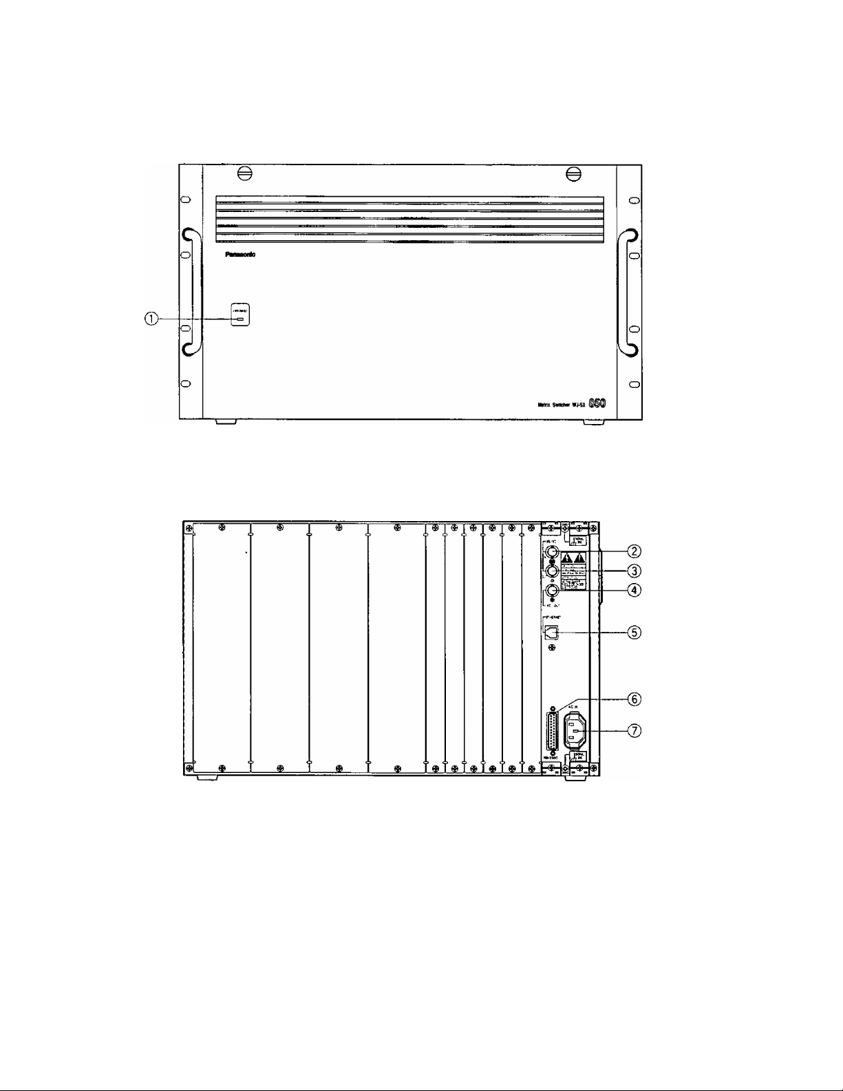
Appearance
Front View
Rear View
(j) Operate Indicator (OPERATE)
ts on when the power of the WJ-SX850 Matrix
Switcher Card Cage is turned on.
Note: The power switch of this cage is located
underneath the front panel.
Remove the front panel by removing two screws
on the panel.
CD VS/VD Input Connector (VSA^D IN)
Accepts either the VD (Vertical Drive) pulse or the
VS (Video Sync) signal for synchronizing the sys
tem.
Notes:
• This input is looped through to the VSA/D Output
Connector.
• When the VD (or VS) signal is supplied to the
VSA/D Input Connector, turn the VS/VD selection
switch (SW7) on the circuit board to the VD (or
VS) position. The factory default setting of the
VS/VD selection switch (SW7) is VD. Ask quali
fied service personnel about setting up this
switch.
• The external sync signal should meet EIA RS-
170 specifications and should not contain any
jitters, such as a VCR playback signal.
-2-
Page 3

(3) VS/VD Output Connector (VS/VD OUT)
Outputs either the VD (Vertical Drive) pulse or the
VS (Video Sync) signal for synchronizing other sys
tem components.
Note: The input at the VS/VD Input Connector is
looped through to this output. These inputs and
outputs are connected internally.
(4) VD Output Connector (VD OUT)
Outputs VD (Vertical Drive) pulses for synchronizing
other system components.
Notes:
• The internal VD pulse or the looped-through
external VD pulse is provided at this connector.
• When the VS signal is supplied to the VS/VD
Input Connector, the VD output signal from the
VD Output Connector will be delayed by
approximately 15 ps with respect to the V-sync
of the VS input signal.
3H V
vs input signal
VD output signal
r
approx. 15 psec
(D Ethernet Port (ETHERNET)
For exchanging control data with
Processing Unit (CPU) via Ethernet.
© RS-232C Port (RS-232C)
This port is used only for factory tests.
(Z) AC Inlet Socket (AC IN)
Plug the power cord (supplied as a standard acces
sory) into this socket and connect the cord to an AC
outlet.
the Central
-3-
Page 4
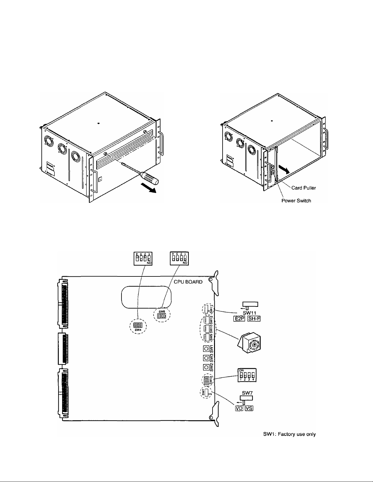
■ Board Setting
The following settings should be made by qualified service personnel or system installers.
1. Remove the front panel by removing two screws on
the panel.
2. Extract the Local CPU board by raising up the card
puller.
— Caution --------------------------------------------------------------------------------------------------------------------------
Hold this board only by its edges. Otherwise components on the board may be damaged by static electricity.
-4.
SW3: LCPU Reset Switch
SW2: Cord Cage Reset Switch
Page 5
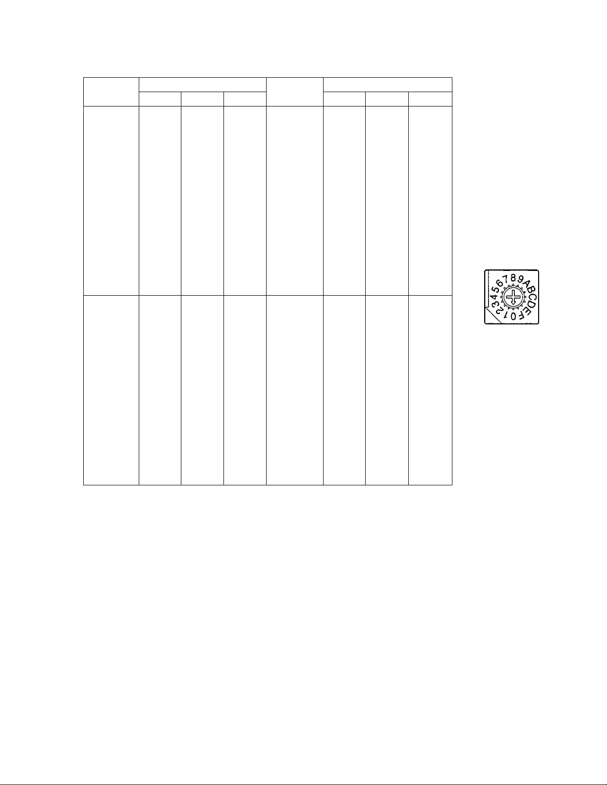
3. Set switches (SW9, SWIO and SW12) on the board to designate the cage number as shown below.
The cage number and corresponding switch settings are given in the following address table.
The factory default setting is 000.
Cage No.
1
2 0 0 2 17 0 1 2
3
4 0 0 4 19 0 1 4
5 0 0 5 20 0
6 0
7 0 0 7 22 0 1
8 0 0 8 23 0
9 0
10 0 0 A 25 0
11
12 0 0 C 27 0 1 C
13 0 0 D 28 0
14 0 0 E 29 0 1 E
15 0 0
241 1 0 1 256
242 1
243
244 1
245 1 0 5 260
246 1
247 1
248 1
249
250 1
251
252 1
253
254 1
255
SW12
SW Setting
SWIO SW9 SW12 SWIO SW9
0 0
0 0 3 18 0
0 6
0 9
0 0 В 26 0
0
1
1
1
1
1
0 3 258
0
0 6 261
0
0 8
0 9
0
0 В 266
0 C
0 D 268
0
0 F 270
1
F
2 257 1 1 2-
4 259 1 1 4
7
A 265 1 1 A
E
Cage No,
16 0
21
24 0 1 9
30 0
262
263 1 1.
264 1 1
267 1 1
269
SW Setting
1 1
1
1
0
1 1 1
1 1
1 1
1 1
1 1
1
1 1
1 1 E
1 1 F
1 6
1
1 A
1 В
1 D
1 F
1 В
3
5
7
8
3
5
6
7
8
9
C
D
Designate further cage numbers, referring to the
above address table.
Cage numbers are available up to 1 024.
4, Set switch (SW7) on the board to select either VD or
VS for the Sync input signal, if applicable. The facto
ry default setting is VD.
SW7
IT
VD VS
5. Confirm that switch (SW11) on the board is set to
E2P position.
SW11
-5-
Page 6
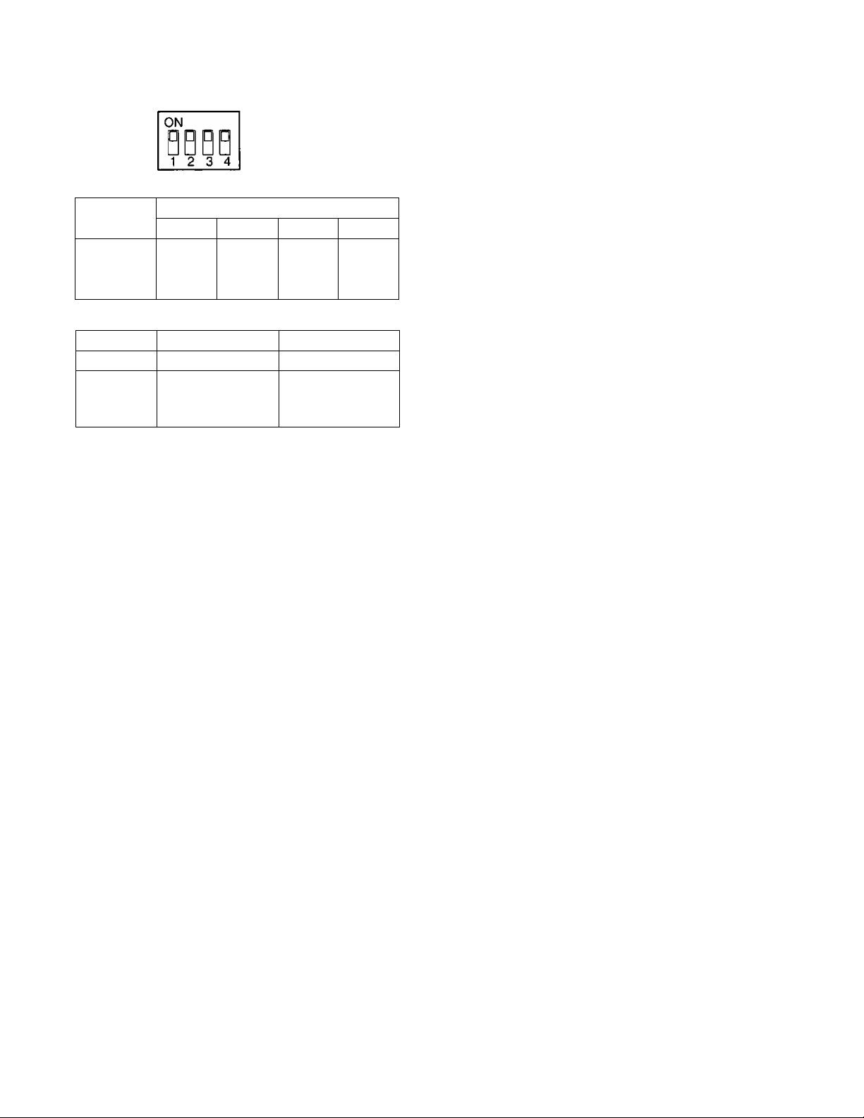
6, Confirm that switches (SW4, SW8 and SW13} on the
board are set as follows:
7. Place the board into the CPU slot in the front of the
cage by sliding it along the board guide.
Switch
Number
SW4 ON OFF ON OFF
SW8
SW13
DIP SW8
1
4
1
ON ON ON ON
OFF OFF OFF OFF
PROM Mode
MAC Address
Write-enable
Setting Positions
2 3
OFF ON
Normal Mode
Normal Mode
Mode
■ Specifications
Power Supply:
Power Consumption:
VSA/D Input/Output:
VD Output:
Ethernet Port;
RS-232C Port:
Ambient Operating Temperature:
Ambient Operating Humidity:
Dimensions:
Weight:
4
120 VAC 60 Hz
150 W (max. 150 W when all slots are occupied)
2(BNC)
Video Level 4 V[p-p]/75 о (BNC)
lOBase-T, 8-conductor modular jack
25-pin D-sub connector
-10°C - -h50°C (14°F- 122°F)
Less than 90 %
430 (W) X 265 (H) X 350 (D) mm
16-15/16" (W) X 10-7/16" (H) X 13-3/4 (D)
13 kg {28,6 lbs)
Weight and dimensions indicated are approximate.
Specifications are subject to change without notice.
Accessory
Power Cord
....................................................
1 pc.
-6-
Page 7

Page 8

Panasonic Security and Digital Imaging Company
A Division of Matsushita Eiectric Corporation of America
Executive Office: One Panasonic Way 3E-7, Secaucus, New Jersey 07094
Regtonai Offices;
Northeast: One Panasonic Way, Secaucus, NJ 07094 (201) 348-7303
Southern: 1225 Northbrook Parkway, Suite 1-160, Suwanee, GA 30024 (770) 338-6838
Midwest: 1707 North Randail Road, Elgin, IL 60123 (847) 468-5211
Western: 6550 Katella Ave., Cypress, CA 90630 (714) 373-7840
Panasonic Canada ine.
5770 Ambier Drive, Mississauga,
Ontario, L4W 2T3 Canada (905)624-5010
Panasonic Sales Company
Division of Matsushita Electric of Puerto Rico ine.
Ave. 65 de Infanteria. Km. 9.5
San Gabriei Industria! Park, Carolina,
Puerto Rico 00985 (809)750-4300
© Matsushita Communication Industrial Co., Ltd. 1999
NM1099-0 YWV8QA5244AN
Printed in Japan
(N) 19
 Loading...