

Page 1
Before attempting to connect or operate this product, please read these instructions completely
Matrix Switcher
WJ-SX550A
System Controller
WV-CU550A
ENGLISH
DEUTSCH
FRANÇAIS
Page 2
The serial number of this product may be found on the
bottom of the unit.
You should note the serial number of this unit in the
space provided and retain this book as a permanent
record of your purchase to aid identification in the event
of theft.
Model No.
Serial No.
THIS APPARATUS MUST BE EARTHED.
To ensure safe operation the three-pin plug supplied must be inserted only into a standard three-pin power point which is effectively
earthed through the normal household wiring. Extension cords used
with the equipment must be three-core and be correctly wired to provide connection to earth. Wrongly wired extension cords are a major
cause of fatalities.
The fact that the equipment operates satisfactorily does not imply
that the power point is earthed and that the installation is completely
safe. For your safety, if in any doubt about the effective earthing of
the power point, consult a qualified electrician.
The lightning flash with arrowhead symbol, within an equilateral triangle, is
interned to alert the user to the presence
of uninsulated "dangerous voltage" within
the product's enclosure that may be of
sufficient magnitude to constitute a risk of
electric shock to persons.
The exclamation point within an equilateral triangle is intended to alert the user
to the presence of important operating
and maintenance (servicing) instructions
in the literature accompanying the appliance.
WARNING:
TO PREVENT FIRE OR SHOCK HAZARD, DO NOT EXPOSE THIS APPLIANCE TO RAIN OR MOISTURE.
CAUTION:
TO REDUCE THE RISK OF ELECTRIC SHOCK,
DO NOT REMOVE COVER (OR BACK), NO USER
SERVICEABLE PARTS INSIDE.
REFER SERVICING TO QUALIFIED SERVICE
PERSONNEL.
CAUTION
RISK OF ELECTRIC SHOCK
DO NOT OPEN
For Australia
FOR YOUR SAFETY PLEASE READ THE FOLLOWING TEXT CAREFULLY.
This appliance is supplied with a moulded three pin mains plug for your
safety and convenience.
A 13 amp fuse is fitted in this plug.
Should the fuse need to be replaced please ensure that the replacement
fuse has a rating of 13 amp and that it is approved by ASTA or BSI to
BS1362.
Check for the ASTA mark
H or the BSI mark G on the body of the
fuse.
If the plug contains a removable fuse cover you must ensure that it is
refitted when the fuse is replaced.
If you lose the fuse cover the plug must not be used until a replacement
cover is obtained.
A replacement fuse cover can be purchased from your local Panasonic
Dealer.
IF THE FITTED MOULDED PLUG IS UNSUITABLE FOR THE SOCKET OUTLET IN YOUR HOME THEN THE FUSE SHOULD BE
REMOVED AND THE PLUG CUT OFF AND DISPOSED OF SAFELY.
THERE IS A DANGER OF SEVERE ELECTRICAL SHOCK IF THE
CUT OFF PLUG IS INSERTED INTO ANY 13 AMP SOCKET.
If a new plug is to be fitted please observe the wiring code as shown
below.
If in any doubt please consult a qualified electrician.
WARNING: This apparatus must be earthed.
IMPORTANT
The wires in this mains lead are coloured in accordance with the following code.
Green-and-yellow: Earth
Blue: Neutral
Brown: Live
As the colours of the wire in the mains lead of this appliance may not
correspond with the coloured markings identifying the terminals in your
plug, proceed as follows.
The wire which is coloured green-and-yellow must be connected to
the terminal in the plug which is marked with the letter E or by the earth
symbol
I or coloured green or green-and-yellow.
The wire which is coloured blue must be connected to the terminal in
the plug which is marked with the letter N or coloured black.
The wire which is coloured brown must be connected to the terminal
in the plug which is marked with the letter L or coloured red.
How to replace the fuse
Open the fuse compartment with
a screwdriver and replace the fuse
and fuse cover.
For U.K.
We declare under our sole responsibility that the product to which
this declaration relates is in conformity with the standards or other
normative documents following the provisions of Directive
EEC/89/336.
Nosotros declaramos bajo nuestra ùnica responsabilidad que el
producto a que hace referencia esta declaraciòn està conforme con
las normas u otros documentos normativos siguiendo las estipulaciones de la directiva CEE/89/336.
Noi dichiariamo sotto nostra esclusiva responsabilità che il prodotto
a cui si riferisce la presente dichiarazione risulta conforme ai
seguenti standard o altri documenti normativi conformi alle disposizioni della direttiva CEE/89/336.
Wij verklaren als enige aansprakelijke, dat het product waarop deze
verklaring betrekking heeft, voldoet aan de volgende normen of
andere normatiefve dokumenten, overeenkomstig de bepalingen
van Richtlijn 89/336/EEC.
Vi erklærer os eneansvarlige for, at dette produkt, som denne
deklaration omhandler, er i overensstemmelse med den følgende
standarder eller andre normative dokumenter i følge bestemmelserne i direktiv 89/336/EEC.
Vi deklarerar härmed värt fulla ansvar för att den produkt till vilken
denna deklaration hänvisar är i överensstämmelse med standarddokument, eller andra normativa dokument som framstölls i Direktiv
89/336/EEC.
Ilmoitamme yksinomaisella vastuullamme, että tuote, jota tämä
ilmoitus koskee, noudattaa seuraavia standardeja tai muita ohjeellisia asiakirjoja, jotka noudattavat direktiivin 89/336/EEC. säädöksiä.
Vi erklærer oss alene ansvarlige for at produktet som denne
erklæringen gjelder for, er i overensstemmelse med følgende
normer eller andre normgivende dokumenter som fælger bestemmelsene i direktiv 89/336/EEC.
FUSE
Page 3

-1-
PREFACE
The WJ-SX550A Matrix Switcher, when combined with the
optional WV-CU550A System Controller and WJ-AD550
Extension Unit, allows for flexible control of 128 cameras
and 16 monitors.
Through the use of user-friendly, on-screen menu setups,
programmable sequences and tours can be easily established for customized security requirements.
The use of modular construction for the WJ-SX550A Matrix
Switcher allows for flexible expansion for future needs.
PRECAUTIONS
• All necessary procedures, with regards to the installation of this unit should be made by qualified service
personnel or system installers.
• Do not attempt to disassemble the unit.
In order to prevent electric shock, do not remove
screws or covers. There are no user-serviceable parts
inside.
Do refer all servicing to qualified service personnel.
• Handle the unit with care.
Do not abuse the unit. Avoid striking, shaking, etc. It
could be damaged by improper handling or storage.
• Do not expose the unit to rain or moisture, or try to
operate it in wet areas.
Do take immediate action if the unit becomes wet.
Turn the power off and refer servicing to qualified service personal. Moisture can damage the unit and also
create the danger of electric shock.
• Do not use strong or abrasive detergents when cleaning the unit body.
Do use a dry cloth to clean the unit when dirty.
In case the dirt is hard to remove, use a mild detergent and wipe gently.
• Do not operate the unit beyond its temperature,
humidity or power source ratings.
Do not use the unit in an extreme environment where
high temperature or high humidity exist.
Use the unit under conditions where temperatures are
within −10°C - +50°C (14°F - 122°F), and humidity is
below 90%.
The input power source is 220 - 240V AC 50 Hz.
FEATURES
The WJ-SX550A Matrix Switcher, when combined with the
WV-CU550A System Controller and WJ-AD550 Extension
Unit enables control of the following functions:
• Routing of up to 128 cameras to any one of 16 monitors.
• Remote control of up to 128 cameras and auxiliary
equipment, by using optional receivers and accessories, including:
1. Remote control of Pan-Tilt Head and Camera
Housing.
2. Remote control of Motorized Zoom Lenses:Focus,
Zoom and Iris.
3. Remote control of camera setting, including
Electronic Sensitivity Up, Electronic Shutter,
Electronic Zoom, and more.
Additional features of the WJ-SX550A include:
Versatile Camera Switching Modes
• Independent programmable sequence for each monitor (16 programs)
• 32 tours including Dwell Time, Camera Preset Position
and AUX Controls for any monitor
• 8 group synchronized sequences including Dwell
Time, Camera Preset Positions and AUX Controls
• Any tours or group synchronized sequence can be
called up by operators manually, by alarm and time
date schedule automatically
Flexible Alarm Activations
• Alarm Mode 1: Single monitor is assigned for auto
alarm call up with single VTR control.
• Alarm Mode 2: 4 monitors are assigned for auto alarm
call up with 4 VTR controls.
• Alarm Mode 3: Any camera, with its preset position,
can be assigned to any monitor.
Alternatively, any tour or group sequence can be
assigned to any monitor or group of monitors.
Programmable System Partitioning and Priority
• Operator Registration: 5 operator access levels to system for setup and operation.
Password protection to limit operators access to system
Operator priority to lock out lower priority operators.
ENGLISH
Page 4

-2-
HOW TO USE THIS MANUAL
The purpose of this manual is to provide step-by-step instructions for setting up and operating a Matrix System 500. If Matrix
Switchers are new to you, it is highly recommended that you read this manual in its entirety. If you are already familiar with Matrix
Switchers you might want to skip over Section 1, Basic Operation of a Matrix Switcher, and go directly to Section 4, Installation and
System Connections. Each section of this manual is briefly described below.
Section 1. Basic Operation of a Matrix Switcher
This section covers the basics of crosspoint switching, spot and sequencing, microprocessor control of switching and camera accessory control.
Section 2. Features of the System 500 Matrix Switcher
The main features of the System 500 are described. Numerous illustrations are included that help to simplify the
explanations. A thorough understanding of key features is very important for proper setup of the system.
Section 3. Detailed Product Description and Selection
Operating controls and their functions are explain in this section. Also, in-depth information about each board is
given here, along with details about proper board setup. A table is included here that specifies how many
optional boards are required for every possible system expansion.
Section 4. Installation and System Connections
Information about cable connections between the Matrix Switcher and System Controllers, cameras, monitors
and peripheral devices is provided here.
Section 5. Software Setup
Step-by-step procedures for successful first time programming of the system are explained in this section.
Graphical representations of the various setup tables are also provided. This section is very important as proper
programming of the system is vital for customizing the system to the end user's requirements.
Section 6. Operating Procedures
After system programming, normal operation of the system on a daily basis is done by following the steps outlined in this section.
Section 7. Troubleshooting
Most of the problems in a Matrix System can be traced to faulty hardware or software setup. This section is
invaluable as an aid in identifying the sources of common problems. Reading this section before requesting service will save you time in resolving those problems.
Section 8. Specifications
Section 9. Index
Page 5

§1 BASIC OPERATION OF A MATRIX SWITCHER PAGE 5 - 10
§2 FEATURE OF THE SYSTEM 500 MATRIX SWITCHER PAGE 11 - 22
§3 DETAILED PRODUCT DESCRIPTION AND SELECTION PAGE 23 - 48
§4 INSTALLATION AND SYSTEM CONNECTIONS PAGE 49 - 64
§5 SOFTWARE SETUP PAGE 65 - 92
§7 TROUBLESHOOTING PAGE 119 - 122
§6 OPERATING PROCEDURES PAGE 93 - 118
§9 INDEX PAGE 127 - 130
§8 SPECIFICATIONS PAGE 123 - 126
-3-
TABLE OF CONTENTS
1
2
3
4
5
6
7
8
9
Page 6

-5-
BASIC
OPERATION
OF
A MATRIX
SWITCHER
1
Page 7
-6-
BASIC OPERATION OF A MATRIX SWITCHER
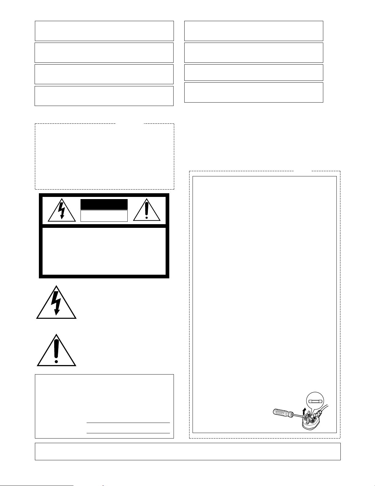
■ Crosspoint Switches
SW11 SW21 SW31 SW41
SW12 SW22 SW32 SW42
SW13 SW23 SW33 SW43
SW14 SW24 SW34 SW44
SW15 SW25 SW35 SW45
SW16 SW26 SW36 SW46
SW17 SW27 SW37 SW47
SW18 SW28 SW38 SW48
All Matrix Switchers, no matter how complicated and sophisticated they may be, depend on crosspoint switches to perform the
basic operations of the switcher. The crosspoint switches form a rectangular array of rows and columns in which any row may be
connected to any column.
In the Matrix Switcher shown above, the rows are connected to video cameras and the columns are connected to video monitors.
By closing a certain crosspoint switch we may connect any camera to any monitor.
In the example above, by closing switch SW12, camera 2 is displayed on monitor 1. Likewise, by closing SW24, camera 4 is displayed on monitor 2. In this example, camera 4 and monitor 3 are also connected, as well as camera 8 and monitor 4.
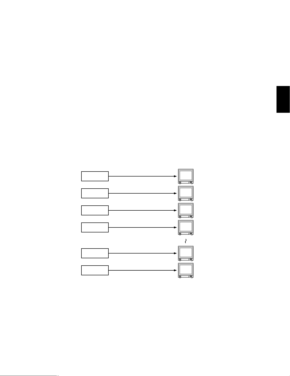
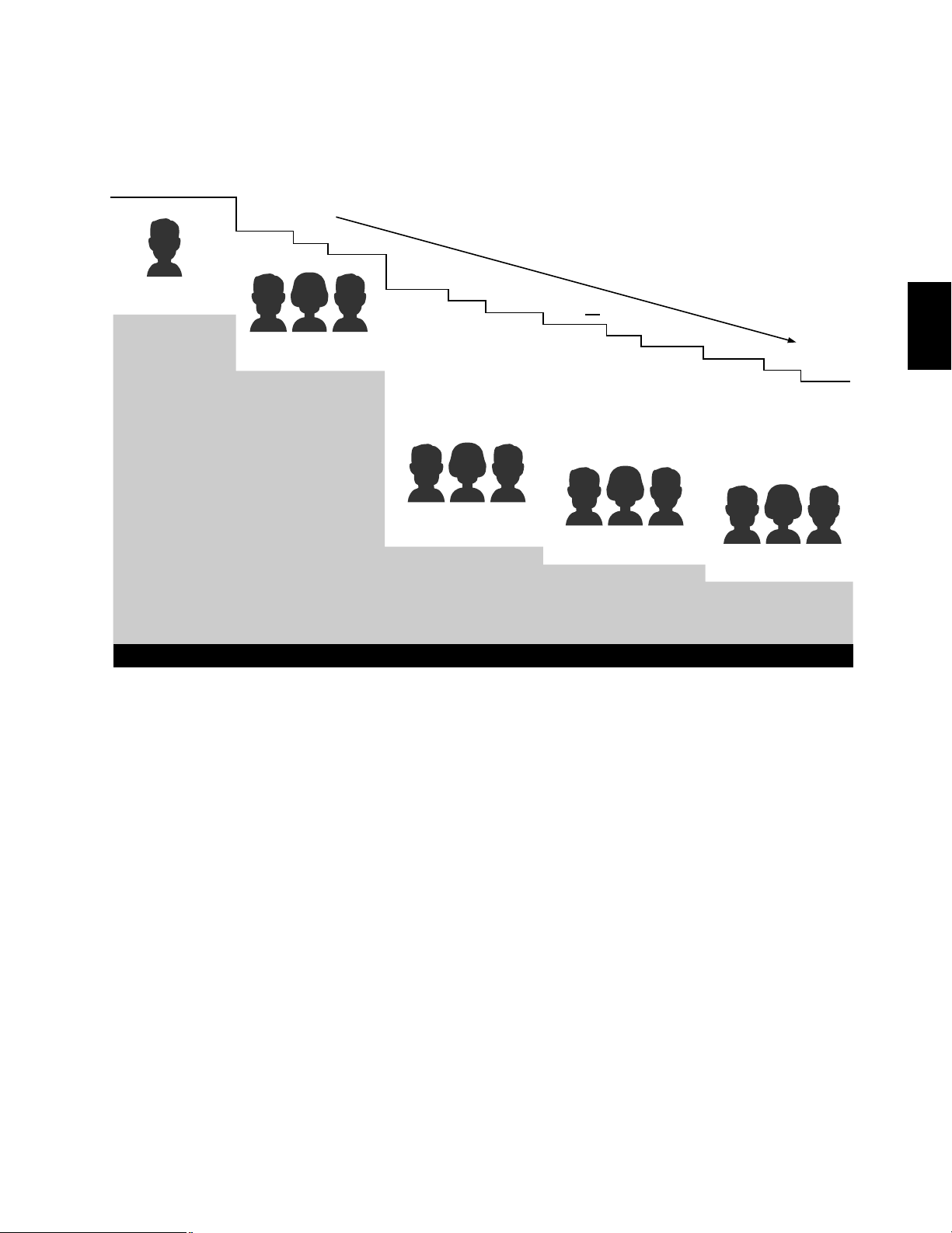
■ Spot and Sequence
Two basic operations of the Matrix Switcher are the SPOT
and SEQUENCE functions. In the SPOT mode a specific
camera is continuously connected to a specific monitor
with no interruption. In the SEQUENCE mode a series of
cameras are displayed in succession on a monitor. If
SW12, SW14 and SW16, of the crosspoint switch array
shown in the previous example, are each closed in a
sequential manner for two seconds, monitor 1 will display
camera images as shown on the right.
The duration of an camera image in a sequence is
called DWELL TIME.
A sequence pattern which repeats itself continuously, such
as the one shown above, can be stored in the memory
section of the Matrix Switcher.
Monitor 1
Dwell time: 2 sec.
Monitor 1 Monitor 2 Monitor 3 Monitor 4
Monitor 1
Dwell time: 2 sec.
Monitor 1
Dwell time: 2 sec.
s
s
s
Camera 1
Camera 2
Camera 3
Camera 4
Camera 5
Camera 6
Camera 7
Camera 8
1
Page 8
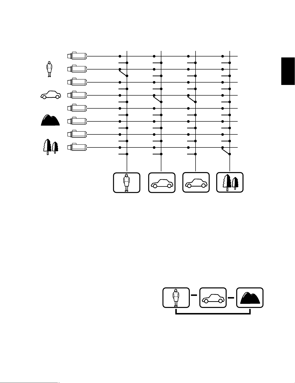
In Matrix Switchers the activation (or closure) of a crosspoint switch is performed by a microprocessor. This microprocessor may
get its commands from one of three sources.
1) From a controller manually operated
2) From an external alarm signal
3) From an internal timer (clock)
Upon receiving a command signal the microprocessor retrieves the sequence pattern, previously stored in memory, and activates
the crosspoint switches in the proper order.
For example:
-7-
■ Activation of crosspoint switches
Matrix Switcher
SW11 SW21 SW31 SW41
SW12 SW22 SW32 SW42
SW13 SW23 SW33 SW43
SW14 SW24 SW34 SW44
SW15 SW25 SW35 SW45
SW16 SW26 SW36 SW46
SW17 SW27 SW37 SW47
SW18 SW28 SW38 SW48
Crosspoint Switch
Sequence Pattern
Alarm
Timer
• Alarm 3 input e Camera 3 picture output to Monitor 1
• 7th January, 10:00AM e sequence of Camera 1 → Camera 2 → Camera 3 output to Monitor 2
Micro-processor
Memory
s
Controller
s
s
s
s
s
1
Page 9
Signal
Synchronizing
Signal (VD2)
Unique VD2 signal is sent to Panasonic cameras to synchronize the cameras with the
Matrix Switcher, thereby preventing rolling during camera picture switching.
-8-
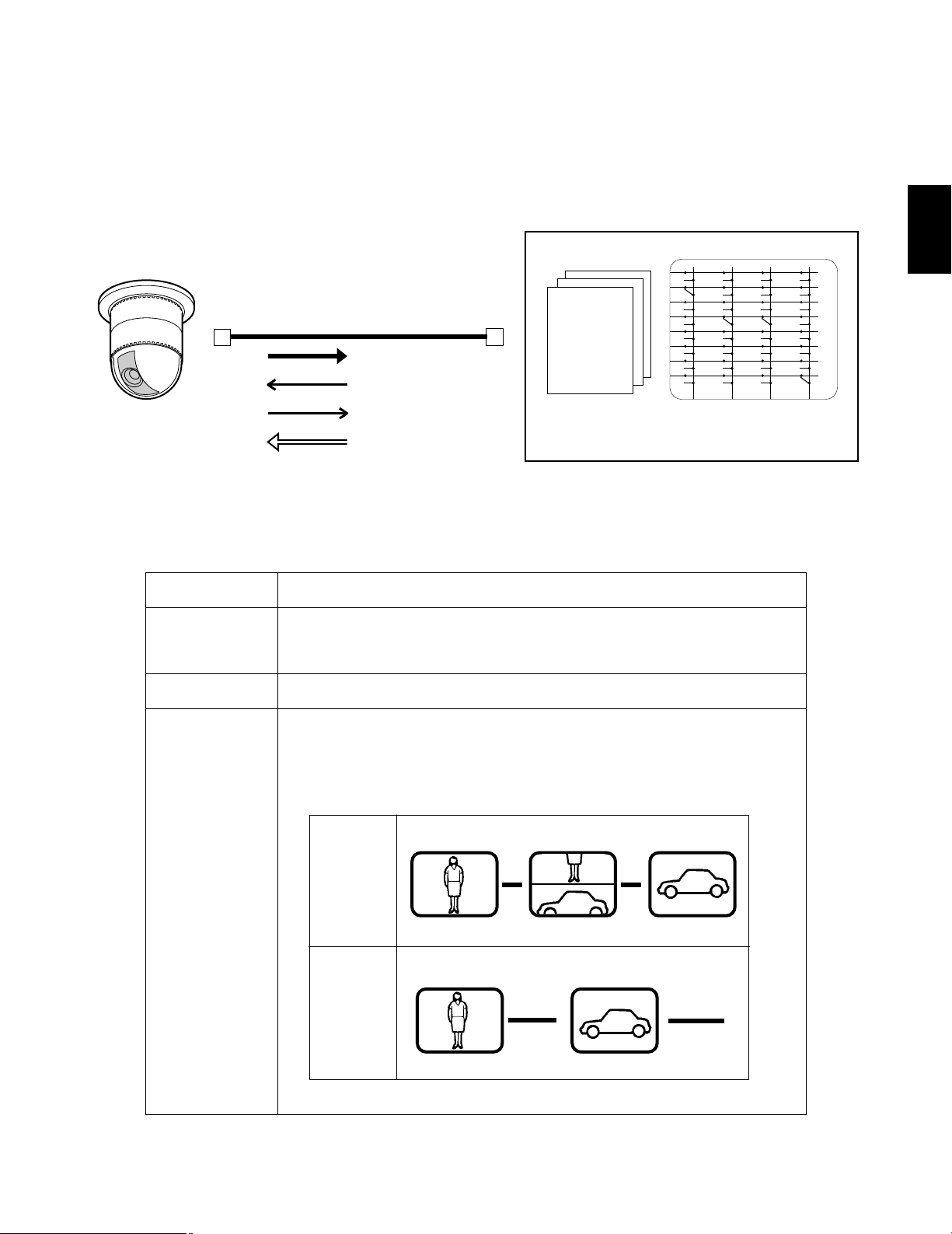
■ Camera, Pan/Tilt Head Control and Camera Synchronization
In addition to controlling the crosspoint switches, the Matrix Switcher can also control external devices such as Pan/Tilt Head
Units, Zoom Lenses and auxiliary circuits through the use of Control Data multiplexed with the video signals.
Also, in cases of Panasonic Matrix Switchers, a unique signal called VD2 is multiplexed with the video signals and is used to synchronize Panasonic cameras to prevent picture rolling during switching between cameras.
Control Data Controls pan, tilt, zoom, focus, iris control shutter speed, back light setting, preset
position, auxiliary control, wiper and defroster.
Status Data Sends camera setting information
s
s
s
SW11 SW21 SW31 SW41
SW12 SW22 SW32 SW42
SW13 SW23 SW33 SW43
SW14 SW24 SW34 SW44
SW15 SW25 SW35 SW45
SW16 SW26 SW36 SW46
SW17 SW27 SW37 SW47
SW18 SW28 SW38 SW48
Crosspoint Switch
Data
multiplex
Sync
signal
All channels provided
with data multiplex and
sync (VD2) generator
as standard features
Matrix Switcher
Coaxial cable
Video Signal
Control
Status Data
Sync. Signal (VD2)
Combination Camera
No
SYNC
(VD2 OFF)
SYNC
(VD2 ON)
s
Function
1
Page 10
-9-
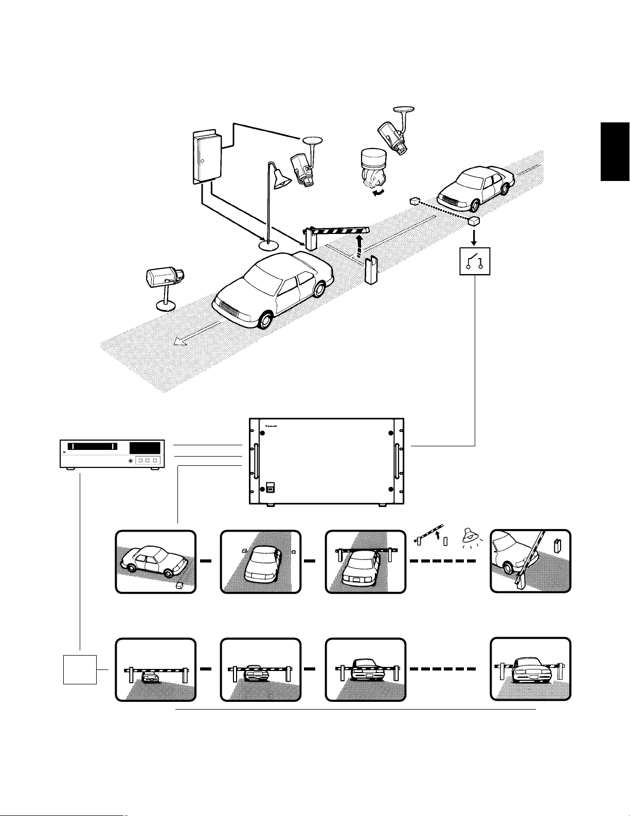
• Examples of Advanced Applications
As previously described, the Matrix Switcher controls both the crosspoint switches and external devices. By combining these two
functions, complicated Systems Control applications can be implemented as shown below.
Light
on
(Aux 2)
Camera 1
Dwell time: 1 sec.
Camera 4/Pre 1
Dwell time: 3 sec.
Camera 4/Pre 2
Dwell time: 2 sec.
Dwell time: 30 sec.
Gate
open
(Aux 1)
s
s
s
Camera 5
s
s
s
Camera 6
Camera 1
Camera 4
Camera 5
Infrared sensor
Aux 1
Aux 2
Receiver
Pre 2
Pre 1
Matrix Switcher WJ-SX550A
TL
Matrix Switcher
Alarm 3
MON 2
Alarm
MON1
VTR
Alarm
Mode
s
s
Monitor 1
Monitor 2
s
t
t
t
Camera 6
s
Real time recording
1
Page 11
-10-
Alarm 3 input by infrared sensor
h
Monitor 1
Monitor 2
Step
(1) Camera 1 picture is shown for 1 second
(2) Camera 4 picture at preset 1 position is shown for 3 seconds
(3) Camera 4 picture at preset 2 position is shown for 2 seconds
(4) Gate open (Auxiliary 1)
Light on (Auxiliary 2)
Camera 5 picture is shown for 30 seconds
Camera 6 spot; alarm sent to Time Lapse VTR to change time lapse mode to real time
mode to record camera 6 in real time.
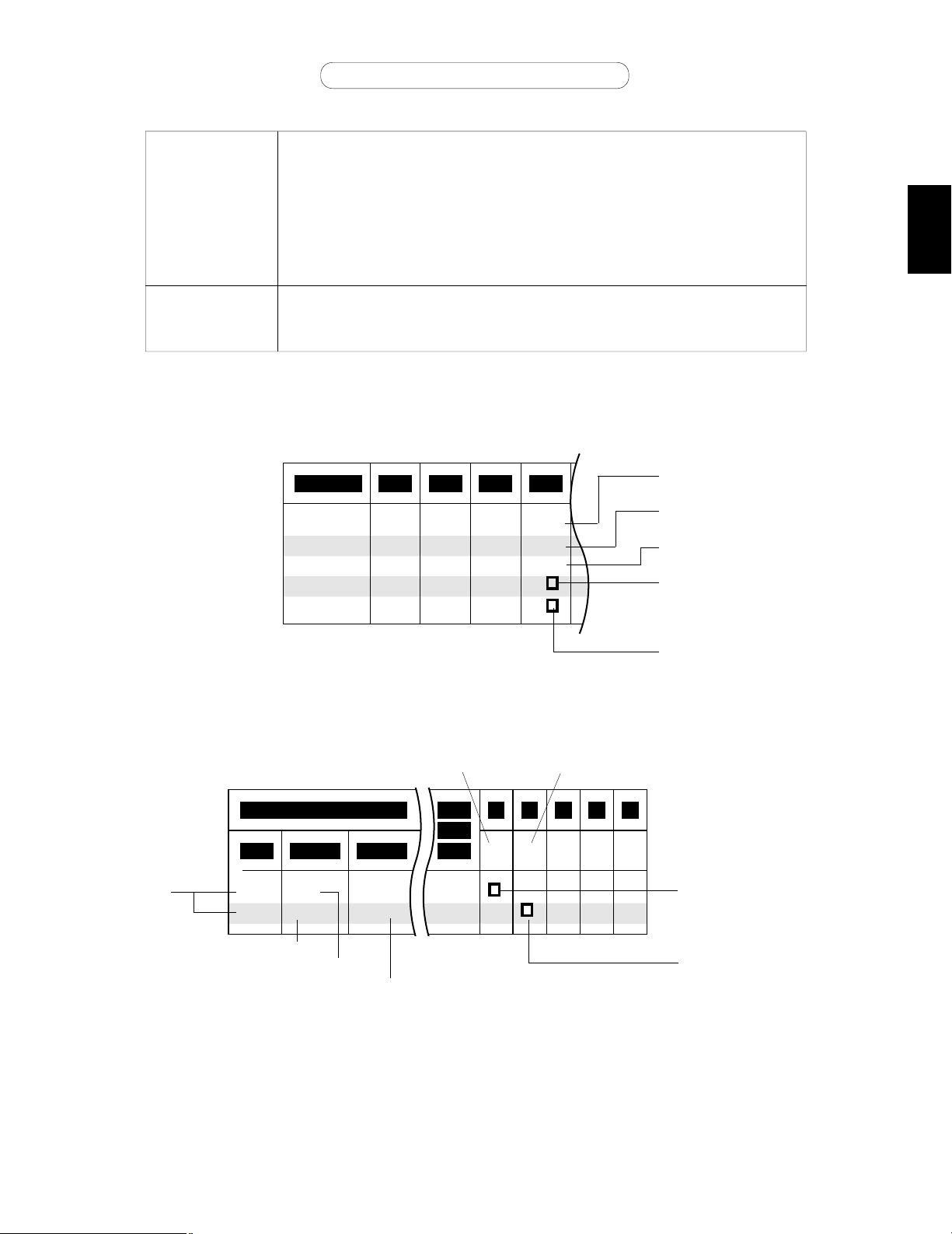
This seemingly complex operation can be performed by the simple settings shown in table 1 and 2.
Step 01
01CAM 04 04 05
02 03 04
01 02
01
DWELL
03 02 30
AUX2
PRE
AUX1
Table 1 (Setup procedure for Tour Sequence)
T103
12
0603
Auto RST
AL CAM
Mode
S
AUX
1 2 3 4 5
TS
Table 2 (Setup procedure for Alarm Activation)
Camera number
Preset camera position
Dwell time in seconds
Gate open
Light on
T1 (Tour Sequence 1)
Alarm Setting
Tour Sequence 1 activated
on Monitor 1
Camera 6 spot on Monitor 2
Alarm 3
Camera No.
Tour Sequence 1
Spot
Monitor 1 is assigned
Tour Sequence
Monitor 2 is assigned
Spot Mode
1
Page 12

-11-
FEATURES
OF THE
SYSTEM 500
MATRIX
SWITCHER
2
Page 13
-12-
FEATURES OF THE SYSTEM 500 MATRIX SWITCHER
Preface
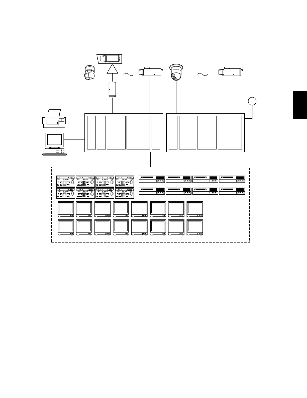
The system shown below is an example of the expansion capabilities of the WJ-SX550A Matrix Switcher.
TL TL TL TL
TL TL TL TL
CPU
Board
Control
Board
WV-PB5504AE
4ch
Output Board
X4
Ext.
Board
WV-PB5508E
8ch
Input Board
X8
Ext.
Board
WV-PB5564E
Alarm
Board
X2
WV-PB5504AE
4ch
Output Board
X4
WV-PB5508E
8ch
Input Board
X8
Camera Input: Up to 128 cameras can be connected. The pan/tilt head, zoom /focus/iris of the lens and AUX switching can be
controlled via a single coaxial cable through a receiver. Also preset control of the lens and pan/tilt head position is possible by
using the WV-CS500 or WV-CS600 Combination Camera System.
Monitor Output: Up to 16 monitors can be connected. The camera title, camera and monitor number and alarm condition can be
displayed on the monitor screen.
System Controller: Up to 8 controllers may be connected. A variety of controls are accessible through the LCD display on the
system controller. Also, access to the Programming Set Up Menu may be gained through the system controller.
VCR: Up to 16 VTRs can be connected. The video signal controlled by the WJ-SX550A Matrix Switcher is supplied to the VTR.
Also, the Matrix Switcher can supply the VTRs with an alarm output signal to switch time lapse recording mode.
Alarm Input: Up to 128 alarm signals can be supplied. An Alarm Sensor Unit with a Normally Open or Normally Closed circuit
should be used.
Printer Output: The Set Up Menu Programming data can be printed out.
RS-232C Port: A Personal Computer can be used instead of the WV-CU550A System Controller.
Note: When using a Personal Computer, the software must be purchased locally (not supplied with WJ-SX550A Matrix
Switcher).
Video Monitor (Max. 16 Output)
Printer
WV-CU550A System Controller (Max 8 Controller)
Max 16 VTR Control Outputs
Computer
RS-232C Port
WJ-SX550A
Matrix Switcher
2
64 cameras 128 cameras
WJ-AD550
Extension Unit
128 Alarm Input
Page 14

-13-
1. Log-in
To operate the Matrix Switcher System 500, a registered
operator must first supply their Operator Number and
Password to the system controller.
The operator number and password are established by
using the Set Up Menu. See page 83 for more details on
operator number registration.
If an attempt is made to enter an operator number and
password that do not match with the registered operator
numbers and passwords, entry into this system is denied.
As shown in the examples below, there are 2 additional
attributes associated with an operator: operator level and
priority. These items are described in more detail on page
19.
Operator Name: Mike
Operator Number: 01
Operator Level: 01
Password: 07171
Priority: 1
Operator Name: Robert
Operator Number: 30
Operator Level: 05
Password: 11524
Priority: 30
Notes:
1. Initially, Operator Number: 1
Password: 12345
are registered at the factory to allow access for first
time system programming.
2. An operator can be logged-in to this system from sev-
eral system controllers.
3. If the main power of the Matrix Switcher is turned off,
log-in procedures must be performed again.
4. If power to the system controller is turned off, the sys-
tem controller will record operating status when power
is resupplied.
2. Camera and Monitor Selection
After log-in, the desired camera and monitor combination
can be selected.
Basically, any combination of camera and monitor, which
are connected to this unit, can be selected as shown
below.
12
3
General Procedures
1. Select the desired monitor. (monitor and controller are
linked.)
2. Select the desired camera (camera and controller are
linked.)
3. The picture of the selected camera is displayed on the
selected monitor.
2-1 Monitor Selection
By selecting the monitor with the System Controller, it is
linked with the System Controller.
At this time, the camera output signal that was last supplied to the monitor is displayed.
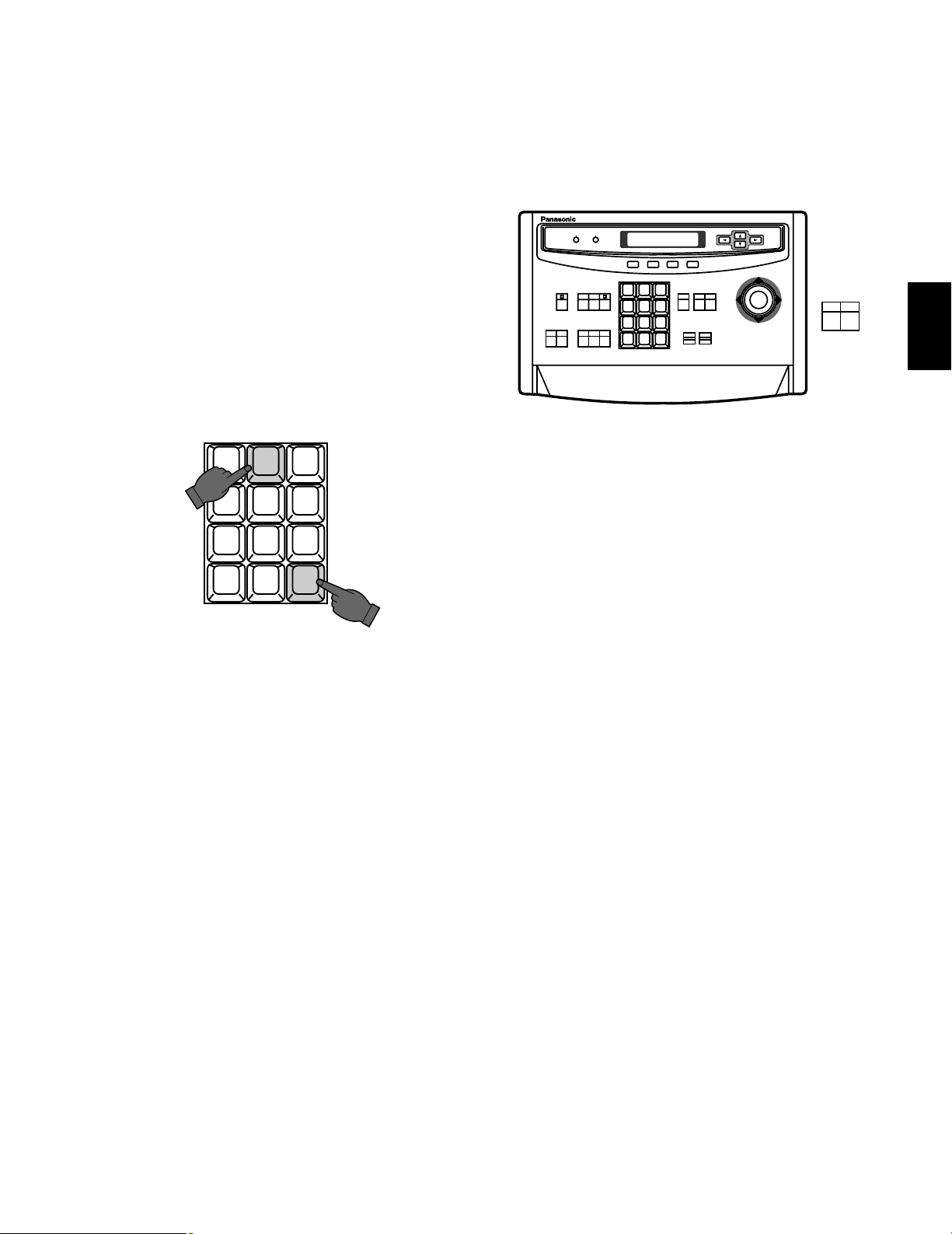
Press the Numeric keys (1 to 16) then press the MON key
to select the desired monitor.
CAM
ESC SET
123
4 5 6
7 8 9
MON
0
For example: When selecting monitor No. 5:
Press 5 then press MON key.
Camera-1 Camera-2
Monitor-1 Monitor-2
WJ-SX550A
Controller
WV-RC150
2
Page 15
-14-
Note: The desired monitor selection may not be avail-
able due to one of the following reasons:
1. The System Controller used for selecting a particular monitor is not allowed access to that monitor
because of keyboard partitioning. See page 20
for more details.
2. The desired monitor is presently selected by
another operator who has a higher operator priority, and therefore, control over that monitor. At this
time "Monitor Busy" or "NOT AVAILABLE" will be
displayed on the System Controller's LCD panel.
2-2. Camera Selection
The video signal from the desired camera can be supplied
to the selected monitor by using the System Controller.
Press the Numeric keys (1 to 128) then press the CAM key
to select the desired camera.
2 3
4 5 6
7 8 9
MON CAM
ESC SET
0
1
For example: When selecting Camera No.2:
Press 2 then press CAM key
Note: The desired camera selection may not be avail-
able due to one of the following reasons:
1. The operator is not allowed access to the desired
camera because the Operator Registration has
limited the operator's access to certain cameras.
See page 19 for more details.
2. The desired camera is currently selected by
another operator who has a higher operator priority, and therefore, control over that camera. At this
time "Camera Busy" will be displayed on the
System Controller's LCD panel.
4. Accessory Control
4-1. Iris Control
This control is used to open or close the iris of specified
DC servo lens with Panasonic WV-BP510, or WV-CP610
series cameras.
3. Camera Control
The selected camera (and, if applicable, the receiver) can
be controlled by the System Controller.
Specified Panasonic cameras, such as the WV-BP510, or
the WV-CP610 series, can have various functions controlled remotely without the need for a receiver.
Note: Because future camera models may have additional
features and functions, please refer to the Operating
Instructions Manual provided with the camera for more
details.
CLOSE
OPEN
IRIS
1 2 3
4 5 6
7 8 9
MON CAM
ESC SET
0
ACK
RESET
BACK
SEQ
FORWARD
SEQ ALT
DEC
-1CAM
INC
+1CAM
STOP12
AUX
CLOSE
OPEN
IRIS
PRESET
FOCUS
NEAR
ZOOM
TELE
FAR
WIDE
System Controller WV-CU 550
LEFT
RIGHT
UP
DOWN
ALARM BUSY
F3 F4F2F1
A
AF
4-2. Pan/Tilt Control
This control is used to pan or tilt the pan/tilt head.
The following operations are available.
1. Manual Operation
Press the Joystick Controller to move the Pan/Tilt head
towards the desired direction. Eight directions are
available: UP / DOWN / RIGHT/LEFT / UP-RIGHT / UPLEFT / DOWN-RIGHT / DOWN-LEFT.
2. Auto Panning Operation
It is necessary to use a Pan/Tilt head such as the WV-
7225.
3. Random Panning Operation
It is also necessary to use a Pan/Tilt head which has
the auto panning capability such as the WV-7225.
4-3. Auxiliary (AUX) Control
This control is used to turn on or off the user’s auxiliary
switches located in the Receiver, such as the WV-RC100,
WV-RC150 or WV-RC170 Receivers.
2
Page 16
-15-
5. Preset Control
The preset function is used to memorize the setting points of focus, zoom, pan and tilt of a desired scene in advance, and to be
able to recall those setting points quickly, according to circumstance.
In addition, if the Camera Position Numbers are registered included the camera numbers with the preset positions in advance, and
to be able to recall those camera position quickly activating the camera selection and preset function at the same time.
This control is available with the Panasonic WV-CS500 or WV-CS600 Combination Camera, which enables the setting and recalling
of the Preset function from the System Controller.
6. Sequence
This system has three kinds of sequential modes: Program, Tour and Group
6-1. Program Sequence
The program sequence is a series of 64 steps assigned to a particular monitor. Each step can have a specific camera assigned to
it.
In the Program Sequence, each monitor has its own specified sequence operation as shown below.
P.SEQ 1
Program Sequence
P.SEQ 2
P.SEQ 3
P.SEQ 4
P.SEQ15
P.SEQ16
Monitor 1
Monitor 2
Monitor 3
Monitor 4
Monitor 15
Monitor 16
2
Page 17
-16-
• Auto Skip Function
The Auto Skip function is available in sequence. If there is no video signal present at a step, the sequence will automatically
skip that step.
This function is enabled with the Programming Set Up Menu.
• Dwell Time
The amount of time each camera is displayed on the monitor (Dwell Time) can be set from 1 sec. to 30 sec. with 1 sec. increments.
This is set with the Programming Set Up Menu.
Also, External Timing, which is controlled from the Time Lapse VTR, can be selected with the Programming Set Up Menu.
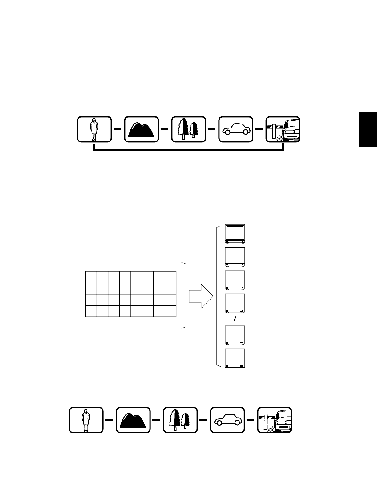
6-2. Tour Sequence
A Tour Sequence consists of 64 steps. Each step has a Camera, Dwell Time, AUX Control and Pan/Tilt Preset assigned to it.
A Tour can be assigned to any monitor.
T1 T2 T3 T4 T5 T6 T7 T8
T9 T10 T11 T12 T13 T14 T15 T16
T17 T18 T19 T20 T21 T22 T23 T24
T25 T26 T27 T28 T29 T30 T31 T32
Tour Sequence
32 Tours In Any Monitor
A total of 32 Tour Sequence can be programmed with the Set Up Menu.
Monitor 1
Dwell time: 3 sec.
Step 1
Monitor 1
Dwell time: 3 sec.
Step 2
Monitor 1
Dwell time: 3 sec.
Step 3
Monitor 1
Dwell time: 3 sec.
Step 4
Monitor 1
Dwell time: 3 sec.
Step 5
s
s
s s
s
Monitor 1
Dwell time: 5 sec.
Step 1
Monitor 1
Dwell time: 3 sec.
Step 2
Monitor 1
Dwell time: 10 sec.
Step 3
Monitor 1
Dwell time: 5 sec.
Step 4
Monitor 1
Dwell time: 3 sec.
Step 5
s
s
s s
Monitor 1
Monitor 2
Monitor 3
Monitor 4
Monitor 15
Monitor 16
2
Page 18
-17-
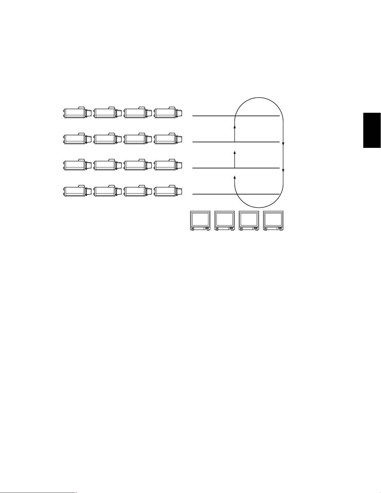
6-3. Group Sequence
A Group Sequence consists of up to 64 steps.
In each step a maximum of 16 cameras can be assigned to 16 monitors.
Pan/Tilt preset and AUX control 1 & 2 can also be set for each camera/monitor combination.
Camera switching (Dwell Time) for each step can be set from 1 sec. to 30 sec. with 1 sec. increments.
There are 8 Group Sequences available, with programming performed in the Set Up Menu.
7. Timer
The timer function is used to program and automatically activate tour or group sequences from set start times to set stop times
during each day of the week and 5 user defined special days.
8. Alarm
8-1. Alarm Input
1. Camera Site Alarm
This alarm signal is supplied from the associated camera site receiver.
The applicable units for camera site alarm inputs are the WV-RC100, WV-RC150 and WV-RC170 Receivers.
2. Interface Alarm
This alarm signal is supplied from the Alarm Input Connector on the optional Alarm Board installed in the WJ-SX550A Matrix
Switcher.
Up to 128 alarm inputs are available.
8-2. Alarm Operation Mode
There are three alarm operation modes available in the WJ-SX550A Matrix Switcher.
The alarm modes are able to switch according to the time programmed in an internal timer.
CAM 13 CAM 14 CAM 15 CAM 16
CAM 9 CAM 10 CAM 11 CAM 12
CAM 5 CAM 6 CAM 7 CAM 8
CAM 1 CAM 2 CAM 3 CAM 4
4th Floor
Group Sequence
C 13 C 14 C 15 C 16
3rd Floor
C 9 C 10 C 11 C 12
2nd Floor
C 6 C 8
1st Floor
C 1 C 2 C 3 C 4
C 5
C 7
Monitor 1 Monitor 2 Monitor 3 Monitor 4
2
Page 19

-18-
The following are the examples of these modes.
Alarm Mode 1: Any alarms to 1 monitor
Mode 1 displays all alarms on Monitor One. If more than one alarm is activated, the system will sequentially display the alarms
on Monitor One.
Alarm Mode 2: Any alarms to 4 monitors
Mode 2 displays the first alarm on Monitor One, the second on Monitor Two, the Third on Monitor Three and the fourth on
Monitor Four. If more than four alarms are activated, the system will sequence the pictures starting on Monitor One, then two,
etc.
Alarm Mode 3: Any alarms to any monitors
Mode 3 is a fully programmable mode. Any alarm can be shown on any monitor plus sequence routines, presets and auxiliary
relays in receivers can be activated.
8-3. Alarm Recall
The WJ-SX550A Matrix Switcher can store up to 99 Alarm Events in its memory.
The alarms may be recalled and displayed, in chronological order, on any desired monitor.
A
1
A
2 3 4
5 6 7 8
Alarm
A
1 2 3 4
5 6 7 8
A
Alarm
C
Alarm
B
Alarm
B
C
Monitors Monitors
Sequence
Monitors
Any sequence, preset and auxiliary control
Any monitors
Sequence
2
Alarm
A
Alarm
B
Alarm
C
Alarm
D
Alarm
E
Alarm
F
1 2 3 4
A
E
B
CD
F
5 6 7 8
1 2 3 4
WZ
ANY
Alarm
5 6 78
XY
Page 20
-19-
9. Operator Registration
In the Operator Registration, an operator's level, priority, password and camera access limits are determined. Up to 30 operators
may be registered.
For example:
9-1. Level Setting
Operator access to various set up functions and system operations is dependent upon the operator's level. There are five separate
levels available, with level 1 being the highest.
9-2. Priority
When two or more operators attempt to perform the same function at the same time, the operator with the higher priority is allowed
to perform the function while the lower priority operator's attempt is denied. There are 30 priority levels available in this system.
9-3. Password
All operators have a five digit long password assigned to them.
9-4. Operator Limits for Camera Access
Access to any camera's video and control of the camera's pan/tilt head may be restricted to certain operators.
10. Camera Title
Camera titles are available for each camera input.
Each title is composed of 15 characters per line, times 2 lines.
34341 3221332132
Level 3
12123
Level 1
OPE-1
1
OPE-5 OPE-6 OPE-7
12341 1244312243
Level 2
OPE-2 OPE-3 OPE-4
43432 4333142341
Level 4
OPE-8 – OPE-26 OPE-27
54343 5656754543
Level 5
OPE-28 OPE-29 OPE-30
Priority
2
3
4
5
6
7
8
26
27
28
29
30
OPERATOR'S LEVEL TABLE
MENU
CAMERA TITLE
TIMER
PROG SEQ
TOUR SEQ
GRP SEQ
PRESET
ALARM
KEY BOARD
OPERATOR
COMP/VD2
CLOCK
CAM SELECT
P-SEQ SELECT
T-SEQ SELECT
G-SEQ SELECT
ALARM ACK/RST
MENU
CAMERA TITLE
TIMER
PROG SEQ
TOUR SEQ
GRP SEQ
PRESET
ALARM
KEY BOARD
CAM SELECT
P-SEQ SELECT
T-SEQ SELECT
G-SEQ SELECT
ALARM ACK/RST
CAM SELECT
P-SEQ SELECT
T-SEQ SELECT
G-SEQ SELECT
ALARM ACK/RST
CAM SELECT
P-SEQ SELECT
T-SEQ SELECT
G-SEQ SELECT
CAM SELECT
P-SEQ SELECT
T-SEQ SELECT
2
Page 21

-20-
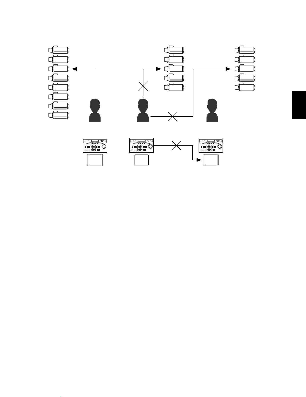
11. Status Display
12. System Controller-Monitor Partitioning
This feature is used to prevent specific WV-CU550A System Controllers from controlling the outputs of specific monitors.
It prevents an operator from unintentionally gaining control over a monitor that may not be associated with their station.
For example:
The following example demonstrates the use of both system controller-monitor partitioning and operator priority.
• Camera: 8 sets
• Monitor: 3 sets
• System Controller: 3 sets
• Operator : 3 persons
SPOT : Spot
P : Program Sequence
T : Tour Sequence
G : Group Sequence
CAM : Camera Setting
SET : Setup
in : Displays video connected to the Video
Output Board
This table shows the system status in real time.
Possible Active modes, as indicated in this table, are defined below.
F : Forward Sequence
B : Backward Sequence
S : Stopped
1 2 3 4 5 6 7 8
M1 M3 M5 M7 M9 M11 M13 M15
M2 M4 M6 M8 M10 M12 M14 M16
System Controller Partitioning To Monitors
WV-CU550A
AL
02
03
05
06
07
08
09
10 in
11
12
13
14
15
16
04
Monitor Camera CTRLR Operator Priority
01
00
01
03
03
02
02
02
11
02
26
01
05
Mode
1121T 1
09
48
63
10
03
35
09
49
53
49
26
01 F
SPOT
T08F
G2S
G2S
G2S
CAM
SPOT
T64F
SPOT
T11F
G1B
G1B
G1B
SPOT
SPOT
2
8
4
17
30
51
10
2
Page 22
-21-
Setting Procedure
1. Operator No.1 has first priority . Cameras 1 - 8 can be selected by MON-1.
2. Operator No.2 has second priority. Cameras 1-5 can be selected by MON-2 (limited access due to operator partitioning).
3. Operator No.3 also has second priority. Cameras 4 - 8 can be selected by MON-3.
1. In the above system, when Operators 1 and 2 both select the camera No.3 simultaneously, the selection by Operator 1 is
allowed because operator 1 has a higher priority.
2. Operator 2 can not select camera 6 because operator's partitioning limits access to only cameras 1 - 5 by Operator 2.
3. Operator 2 can not control the Monitor 3 because controllers partitioning prevents access to monitor 3 by Operator 2.
13. Synchronizing the Sequence with External Timing
The camera switching interval (Sequence Dwell Time) can be synchronized with the time lapse mode set in the associated Time
Lapse VTR.
Select the On or Off mode to meet monitor requirements.
14. Cable Compensation / VD2
Cable Compensation
This feature is used to compensate for signal loss due to cable length.
The most suitable position for cable-loss compensation can be selected in the Set Up Menu.
Available cable length compensations are shown below.
S: Up to 500m (1,600 ft)
M: 500m (1,600 ft) to 900m (2,900 ft)
L: 900m (2,900 ft) to 1,200m (4,000 ft)
(When using 5C - 2V coaxial cable or equivalent)
VD2 (Camera Gen-lock Signal)
The VD2 (Gen-lock Sync Signal) can be turned On or Off by using the Set Up Menu.
Select VD2 On or Off to meet camera requirements.
15. RS-485 Site Communication
The communication parameters between the Camera Site can be set by using the Set Up Menu, if the optional WV-PB5548E Data
Board is installed in the Matrix Switcher.
The WV-RM70E Camera Controller or a modem is required in the system.
1
2
3
4
5
6
7
8
1
2
3
4
5
4
5
6
7
8
M1
SPOT
Controller 1
Operator 1
Priority 1
M2
SPOT
Controller 2
Operator 2
Priority 2
M3
SPOT
Controller 3
Operator 3
Priority 2
Controller
Partitioning
Operator's
Partitioning
Operator's
Priority
2
Page 23
-22-
16. Communication Speed
The data transmitting/receiving rate can be set by using the Set Up Menu.
Usually, the Baud Rate is set to 9,600 bps, with a Wait Time of 100 ms.
Note: Be sure to select the correct speed when using a modem.
17. Clock
A real time, on-screen clock display is available.
The date and time can be set with the Set Up Menu.
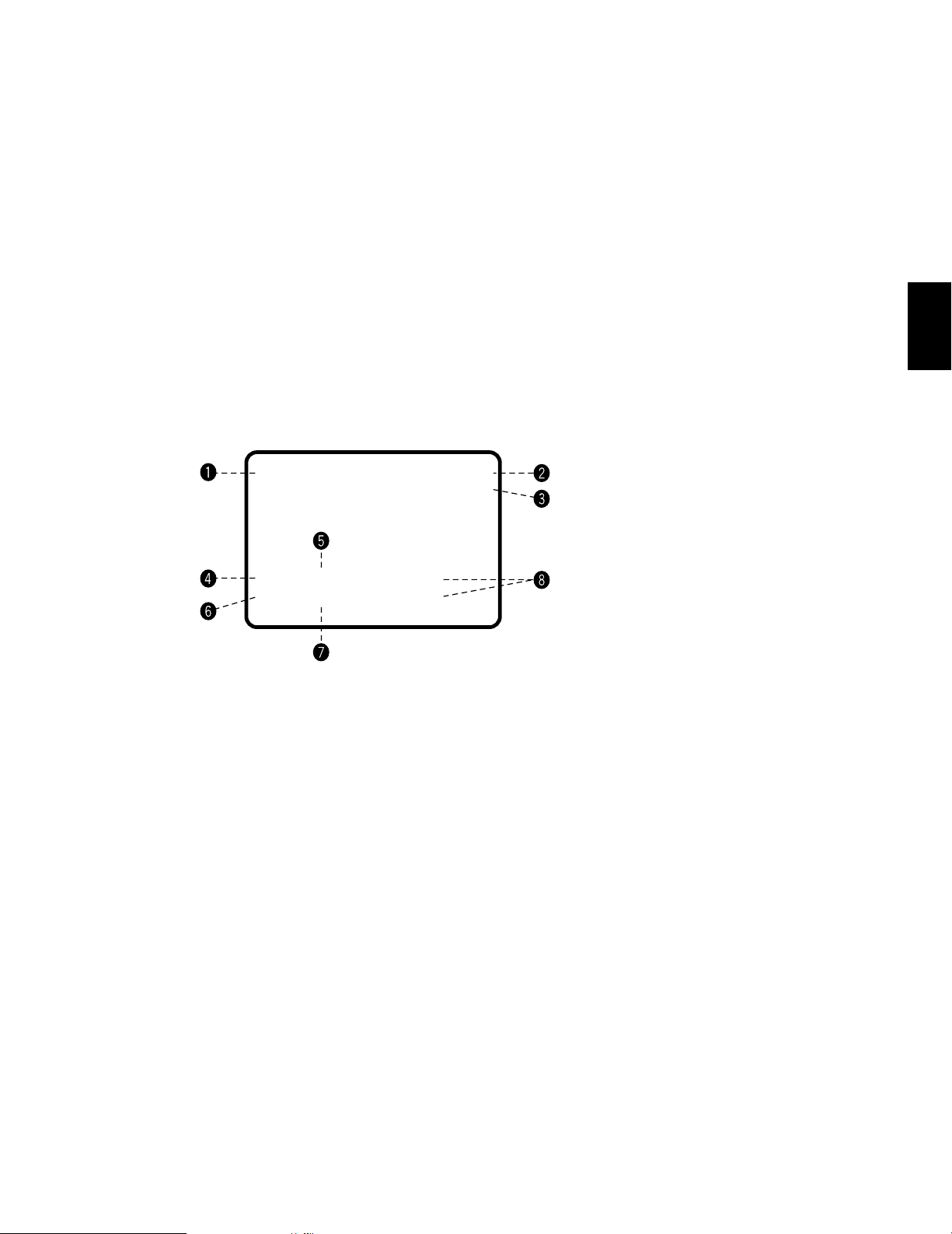
18. On Screen Display
The following item can be displayed on the selected monitor screen.
All items, except Alarm On/Off and Timer mode, can be displayed or removed.
Note: If the monitor used has excessive overscan, parts of the display may be cut off.
19. Printer
A parallel printer can be used to print out the Status, Alarm Recall or Set Up data.
The recommended printer to use is the Panasonic KX-P1624 Impact Dot Matrix Printer.
20. RS-232C Port
This port used for connecting with a Personal Computer. The memory of the WJ-SX550A Matrix Switcher can be loaded or saved.
Also, a Personal Computer can be substituted for the WV-CU550A System Controller.
Note: The software required for this operation, is an optional purchase.
q Date and Time
w Alarm On/Off
AL0: Camera Site Alarm
AL1: Interface Alarm
e Timer Mode
r Camera No.
t Monitor No.
y Preset No.
u Sequence Mode in Effect
i Camera Title
2
07,MAY'96 14:23:56 AL1
/T32
C 01 M16 3rd Floor
Pr64 T32 Room 306
(
)
Page 24

-23-
DETAILED
PRODUCT
DESCRIPTION
AND
SELECTION
3
Page 25
-24-
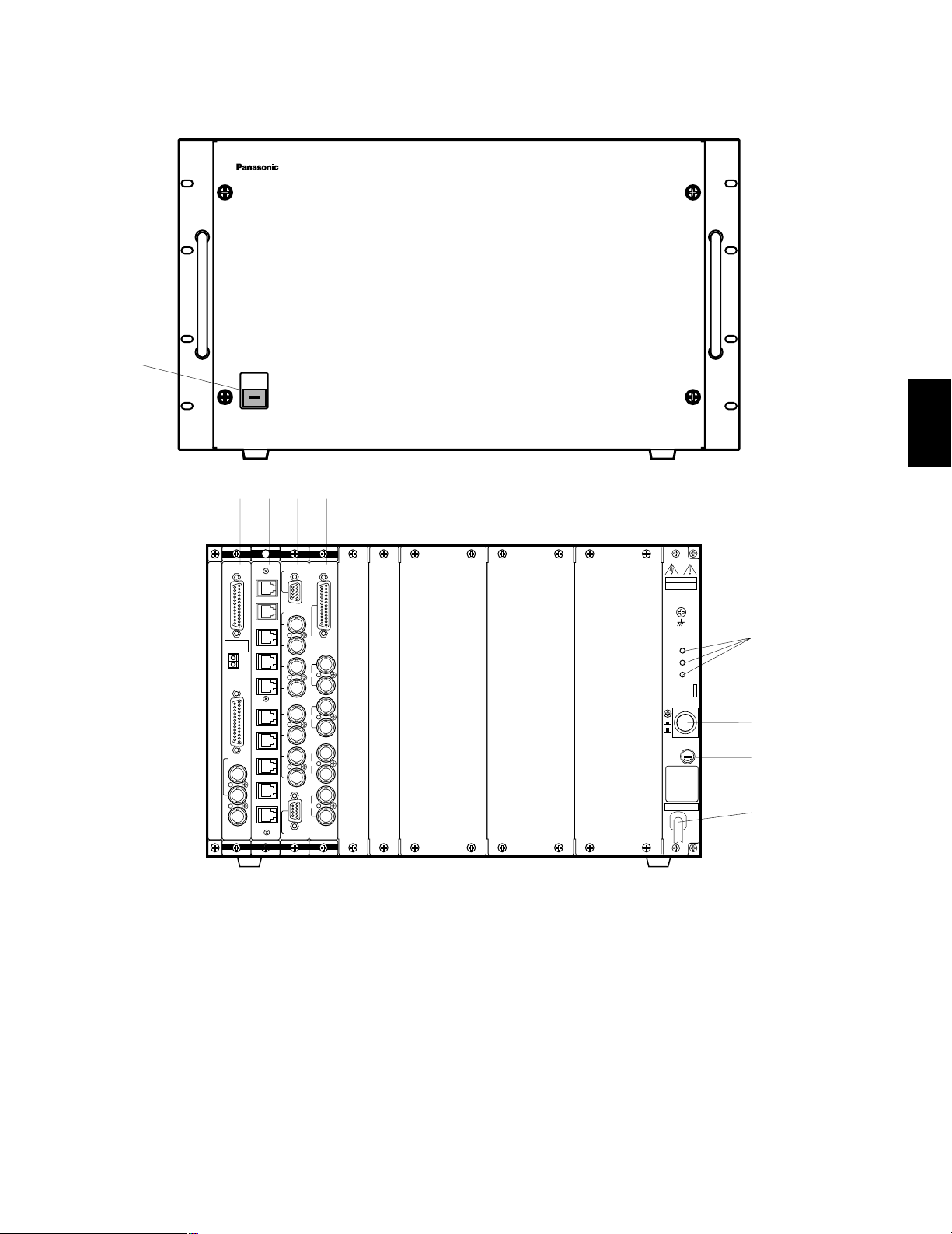
MAJOR OPERATING CONTROLS AND THEIR FUNCTIONS
WJ-SX550A Matrix Switcher
1. Operation Indicator (OPERATE)
This indicator lights up when the WJ-SX550A Matrix
Switcher is turned power on.
2. CPU Board (CPU)
The personal computer and printer connect to this
board.
Refer to the CPU Board on page 25 for more details.
3. Control Board (CONTROL)
The system controller connects to this board.
Refer to the Control Board on page 28 for more
details.
4. Video Input Board (INPUT)
The cameras and receivers connect to this board.
Refer to the Video Input Board on page 30 for more
details.
5. Video Output Board (OUTPUT)
The monitors connect to this board.
Refer to the Video Output Board on page 32 for more
details.
6. Voltage Indicator (+9V, +5V, −5V)
These LEDs indicate the presence of +9V, +5V and
−5V regulated DC voltages.
7. Power On/Off Switch (POWER ON/OFF)
This switch is used to turn the Matrix Switcher power
on or off.
8. Fuse Holder
9. Power Cord
OPERATE
Matrix Switcher WJ-SX
550A
CPU
RS-232C
TIME
ADJUST IN
COM
PRINTER
OUT
IN
VS/VD
VD
OUT
OFF
+9V
+5V
−5V
POWER
ON
11A00001
INPUT
1
2
3
4
5
6
7
8
CAMERA IN
VIDEO OUT1
VIDEO OUT2
OUT
IN
1
OUT
IN
2
OUT
IN
3
OUT
IN
4
MONITOR
ALARM OUT
RESET OUT
EXT TIMING IN
RECOVER IN
OUTPUT
CAUTION
125V 4V
CONTROL
DATA 1
DATA 2
DATA 3
DATA 4
DATA 5
DATA 6
DATA 7
DATA 8
DATA 1
DATA 2
q
wert
y
u
i
o
3
Page 26
Pin No.
Pin No.
-25-
CPU Board
1. RS-232C Port (RS-232C)
This port is used to connect a personal computer that can store or load the memory in the WJSX550A Matrix Switcher. Also, this port enables control of the Matrix Switcher with a personal
computer instead of the WV-CU550A System Controller (by using optional software).
2. Time Adjustment Input Connector (TIME ADJUST IN)
This connector accepts the time adjustment signal from a Time Lapse VTR. It enables the time
display of the WJ-SX550A Matrix Switcher and the Time Lapse VTR to be matched.
Pin No. Designation Direction
1
2
3
4
5
6
7
8
20
(FG)
SD
RD
RS
CS
DR
SG
CD
ER
PC → Switcher
PC ← Switcher
PC → Switcher
PC ← Switcher
PC ← Switcher
PC ← Switcher
PC → Switcher
Other pins are not used.
Designation
1
2
Signal
Ground
Designation Direction
1
2
3
4
5
6
7
8
9
10
11
12
13
14
15
16
17
18
19
20
21
22
23
24
25
/STROBE
DATA 0
DATA 1
DATA 2
DATA 3
DATA 4
DATA 5
DATA 6
DATA 7
/ACK
BUSY
(R)
(G)
(B)
(SYNC)
/PRIM
Not used
Not used
Ground
Ground
Ground
Ground
Ground
Ground
Ground
Printer ← Switcher
Printer ← Switcher
Printer ← Switcher
Printer ← Switcher
Printer ← Switcher
Printer ← Switcher
Printer ← Switcher
Printer ← Switcher
Printer ← Switcher
Printer → Switcher
Printer → Switcher
Monitor ← Switcher
Monitor ← Switcher
Monitor ← Switcher
Monitor ← Switcher
Printer ← Switcher
3. Printer Port (PRINTER)
This port is used to connect a parallel printer which can provide a print out of the Status, Alarm
Recall or Set Up operation data.
CPU
RS-232C
TIME
ADJUST IN
COM
PRINTER
OUT
IN
VS/VD
VD
OUT
q
w
e
r
t
t
TIME
ADJUST IN
COM
1
2
25
13
1
14
25
13
1
14
Note: If a printer is not used in the
system, pins 12 - 15 may be
used to supply system status to
a monitor (RGB type input).
3
Page 27

This board should be installed in the WJ-SX550A Matrix Switcher even if the WJ-AD550
Extension Unit is used.
-26-
4. VS/VD Input Connector (VS/VD IN)
Either the VD (Vertical Drive) pulse or the VS (Video, Sync) signal can be supplied to this connector for synchronizing the system.
Notes:
1. This input is a looping through connection to the VS/VD Output Connector.
2. When the VD (or VS) signal is supplied to the VS/VD Input Connector, turn the VD/VS selection switch (SW4) on the circuit
board to the VD (or VS) position. Initially, the VD/VS selection switch (SW4) is set to the VS position at the factory. Ask
qualified service personnel about setting up this switch.
3. The external sync signal should meet with EIA RS-170 specifications and should not contain any jitter, such as a VTR
playback signal.
5. VS/VD Output Connector (VS/VD OUT)
Either the VD (Vertical Drive) pulse or the VS (Video, Sync) signal is provided at this connector for synchronizing other system
components.
Note: This output is a looping through output of the VS/VD Input Connector. These inputs and outputs are connected internal-
ly.
6. VD Output Connector (VD OUT)
The VD (Vertical Drive) pulse is provided at this connector for synchronizing other system components.
Notes:
1. The internal VD pulse or the looping-through external VD pulse will be provided at this connector.
2. When the VS signal is supplied to the VS/VD Input Connector, the VD output signal from the VD Output Connector will be
delayed by approximately 15 µsec with respect to the V-sync of VS input signal.
By changing the position of jumper connector (CN14) on the board, this connector can be used as the monitor output for the
system status display. (Set Up Menu is displayed during Set up mode.)
VS input signal
VD output signal
approx. 15 µsec
3H V
3
Caution
Page 28

-27-
■ CPU Board Dip Switch and Jumper Setting
2. Set the switch (SW4) on the board to match the Sync. input signal, if applicable. Initially, VS
position is selected at the factory.
3. Set the jumper connectors (CN12) on the board to open connection position when a printer is
connected to the board.
4. Set the jumper connector (CN13) on the board to the “C/L” position when the set up menus are
not clearly displayed on the colour monitor.
Initially, the “B/W” position is selected at the factory.
5. Set the jumper connector (CN14) on the board for either VD Output or Status Output from the
VD Output Connector. Initially, the VD position is selected at the factory.
1. Confirm Switches (SW2) on the board are set to the following positions.
CN13
CN12
SW4
CN14
1234
OFF
5678
SW2
CN14
GRAPHIC
VD
CN14
CN13
B/W
C/L
CN13
R
B
G
SYNC
CN12
1234
OFF
SW2
5678
3
These switches are used only for factory test.
Always keep these switches in the positions shown on right in the field.
Note
Page 29

Pin No.
-28-
Control Board
1. Data Port (DATA 1 - 8)
These ports are used to transmit/receive control data to/from the WV-CU550A System
Controller. Eight ports are available on the board. Connect supplied 6-conductor cable
assembly or use data grade cable, suitable for RS-485 (2 shielded, twisted pairs). Cable length
may be extended up to 1,200m (4,000 ft).
Designation Direction
1
2
3
4
5
6
Ground
T (A)
T (B)
R (A)
R (B)
Ground
Controller → Switcher
Controller → Switcher
Controller ← Switcher
Controller ← Switcher
2. Test Port (TEST 1, 2)
These ports are used only for factory test.
CONTROL
DATA 1
DATA 2
DATA 3
DATA 4
DATA 5
DATA 6
DATA 7
DATA 8
TEST 1
TEST 2
q
w
3
This board should be installed in the WJ-SX550A Matrix Switcher even if the WJ-AD550
Extension Unit is used.
Caution
6
1
Page 30
-29-
■ Control Board Dip Switch Setting
Confirm switches (SW2) on the board are set to the following positions.
These switches are used only for factory test.
Always keep these switches in the “OFF” positions in the field.
Note
1234
OFF
SW2
1234
OFF
SW2
3
Page 31

Pin No.
-30-
WV-PB5508E Video Input Board
1. Video Output Connector (VIDEO OUT 1, 2)
The video signal connected to the Camera Input Connector (CAMERA IN) is looped through to
this connector with 75 ohms termination.
The camera control signal multiplexed on the video signal has been eliminated at this connector. When the Power Switch of the Matrix Switcher is turned off no signal is obtained at this connector.
BNC female connectors are available by use of optional WV-CA64 loop through cable.
2. Camera Input Connector (CAMERA IN, 1 - 8)
This connector accepts either a colour or B/W composite video signal from the camera.
Also, VD2, to synchronize cameras in vertical timing, and data, to control camera site devices
such as receivers, intelligent cameras, and combination cameras, are multiplexed through this
connector.
1
2
3
4
5
6
7
8
9
Not used
CH1
Ground (CH1)
CH2
Ground (CH2)
CH3
Ground (CH3)
CH4
Ground (CH4)
Not used
CH5
Ground (CH5)
CH6
Ground (CH6)
CH7
Ground (CH7)
CH8
Ground (CH8)
VIDEO OUT1VIDEO OUT
2
9
8
7
6
5
4
3
2
1
INPUT
1
2
3
4
5
6
7
8
CAMERA IN
VIDEO OUT1
VIDEO OUT2
q
w
3
Page 32

-31-
■ WV-PB5508E Video Input Board Dip Switch Setting
Set switches (SW1) on the board to meet the camera input number as shown in the following table.
Initially, camera input 1-8 is selected at the factory.
1234
OFF
SW1
3
BOARD
NO.
1234
OFF
1234
OFF
1234
OFF
1234
OFF
1234
OFF
1234
OFF
1234
OFF
1234
OFF
1234
OFF
1234
OFF
1234
OFF
1234
OFF
1234
OFF
1234
OFF
1234
OFF
1234
OFF
1
2
3
4
5
6
7
8
9
10
11
12
13
14
15
16
1-8
9-16
17-24
25-32
33-40
41-48
49-56
57-64
65-72
73-80
81-88
89-96
97-104
105-112
113-120
121-128
CAMERA
IN NO.
SW1 SETTING
• The Camera Inputs 65 to 128 are only used when the WJAD550 Extension Unit is used.
• The Board Number 1 to 8 should be installed in the WJSX550A Matrix Switcher and the Board Number 9 to 16 are
installed in the WJ-AD550 Extension Unit.
Do not install more than nine(9) boards in the WJ-SX550A
Matrix Switcher.
Caution
Page 33

-32-
3
OUT
IN
OUT
IN
OUT
IN
OUT
IN
MONITOR
ALARM OUT
RESET OUT
EXT TIMING IN
RECOVER IN
OUTPUT
1
2
3
4
■ WV-PB5504AE Video Output Board
1. Alarm Output/Reset Output Connector (ALARM OUT/RESET OUT)
External Timing Input Connector (EXT TIMING IN)
Recover Input Connector (RECOVER IN)
ALARM OUT: When the Matrix Switcher receives an alarm from the WV-PB5564E Alarm Board
or camera site receivers WV-RC100, WV-RC150 or WV-R170, the alarm output signal is
provided at this connector for the Time Lapse VTR. The active pin number of the alarm output depends on the alarm mode set by the on-screen program (Mode-1, Mode-2, Mode-3).
RESET OUT: When the Matrix Switcher resets the activated alarm, the alarm reset output sig-
nal, either Open Collector or pulse, is provided at this connector for the Time Lapse VTR.
EXT TIMING IN: The camera switching interval (Sequential Dwell Time) can be synchronized
with the lapse mode set in the Time Lapse VTR.
EXT. TIMING IN 1 controls Monitor 1 output, EXT. TIMING IN 2 controls Monitor 2 output, etc.
Supply the camera switching pulse from the Time Lapse VTR to this connector. Minimum
duration for camera switching pulse needs to be more than one (1) second.
RECOVER IN: This connector accepts the alarm recover signal from the Time Lapse VTR.
q
w
25
13
24
23
22
21
20
19
18
17
16
15
14
12
11
10
9
8
7
6
5
4
3
2
1
Pin No. Designation
1
2
3
4
5
6
7
8
9
10
11
12
13
14
15
16
17
18
19
20
21
22
23
24
25
ALARM OUT 1
RESET OUT 1
RECOVER IN 1
Ground
EXT TIMING IN 1
Ground
ALARM OUT 2
RESET OUT 2
RECOVER IN 2
Ground
EXT TIMING IN 2
(+5V DC)
ALARM OUT 3
RESET OUT 3
RECOVER IN 3
Ground
EXT TIMING IN 3
Ground
ALARM OUT 4
RESET OUT 4
RECOVER IN 4
Ground
EXT TIMING IN 4
Ground
Ground
2. Monitor Input/Output Connector (MONITOR IN/OUT)
OUT: The video signal selected by the Matrix Switcher is provided at this connector for the
video monitor.
IN: This connector is used for video input from a VTR or system expansion to 128 camera input.
Page 34

-33-
■ WV-PB5504AE Video Output Board Dip Switch Setting
1. Set switches (SW1) on the board to meet the monitor output number as shown in the following table.
Initially, monitor 1 - 4 is selected at the factory.
3
Be careful when setting these switches as the switches are not physically located on the
board in numerical order. Switch location from the top of the board, going downward, is: SW4
(reset out 3), SW5 (reset out 4), SW3 (reset out 2) and SW2 (reset out 1).
2. Set switches (SW2/SW3/SW4/SW5) on the board to choose the alarm reset output signal as
either Open Collector (OPEN C.) or Pulse (VTR).
Open Collector (OPEN C.): 16VDC 100mA max.
Pulse (VTR): +5VDC approx. 500 msec.
Initially, VTR positions are selected at the factory.
Note
BOARD
NO.
1234
OFF
1234
OFF
1234
OFF
1234
OFF
1234
OFF
1234
OFF
1234
OFF
1234
OFF
1
2
3
4
5
6
7
8
1-4
5-8
9-12
13-16
1-4
5-8
9-12
13-16
MONITOR
OUT NO.
SW1 SETTING
1234
OFF
SW1
SW4
SW5
SW3
SW2
12
OFF
SW6
SW100
SW150
SW200
SW250
CH1
OPEN C
VTR
3. Set switches (SW100/SW150/SW200/SW250) on the board to choose the
character display mode on the monitor.
NOR: White with Black border
REV: Black with White border
Initially, normal (NOR) positions are selected at the factory.
4. Confirm switches (SW6) on the board are set to the following positions.
NOR REV NOR REV
NOR Position
REV Position
PAL TEST
NOR
SW6
NTSC
OFF
12
These switches are used only for factory test.
Always keep these switches in the positions shown on right in the field.
Note
BOARD
NO.
1 (5)1234
2 (6)5678
3 (7) 9 10 11 12
4 (8) 13 14 15 16
MONITOR OUT NO.
SW100 SW150 SW200 SW250
• The Board Number 5 to 8 are only used when the WJ-AD550
Extension Unit is used.
• The Board Number 1 to 4 should be installed in the WJ-SX550A
Matrix Switcher and the Board Number 5 to 8 are installed in the WJAD550 Extension Unit. Do not install more than five (5) boards in the
WJ-SX550A Matrix Switcher.
Caution
Page 35

-34-
1 2 3
4 5 6
7 8 9
MON CAM
ESC SET
0
ACK
RESET
BACK
SEQ
FORWARD
SEQ ALT
DEC
-1CAM
INC
+1CAM
STOP12
AUX
CLOSE
OPEN
IRIS
PRESET
FOCUS
NEAR
ZOOM
TELE
FAR
WIDE
System Controller WV-CU 550
LEFT
RIGHT
UP
DOWN
ALARM BUSY
F3 F4F2F1
CONTROLLER
ON OFF
IN OUT
TERM
ON OFF
DATA
0
1
2
3
4
5
6
7
8
9
CONTROLLER
UNIT NO.
1-8
A
AF
MODE
qw e r t
y
u
io!0 !1 !2 !3 !4 !5 !6 !7
!8
!9
@0
@1
@2 @3 @4 @6 @7
@5
WV-CU550A System Controller
3
Page 36

-35-
1. Alarm Indicator (ALARM)
This LED indicator blinks to indicate an alarm condition exists.
2. Busy Indicator (BUSY)
This LED indicator lights up when one or more System
Controllers with a higher operator priority than this one
are used to perform a function with the same camera
or monitor at the same time.
While this indicator is lighted, operations from this
System Controller are deactivated and can not be
performed until the indicator goes off.
3. Function Keys (F1/F2/F3/F4)
These keys are used to select functions displayed on
the Liquid Crystal Display.
4. Liquid Crystal Display
This displays function menus and function status.
In this Instructions Manual it is hereafter referred to
as the “LCD”.
5. Cursor Keys (A, C, D, B)
These keys are used to select which function menus
are displayed on the LCD.
6. Joystick Controller (UP/DOWN/LEFT/RIGHT)
This Joystick is used to operate the Pan/Tilt Head
manually, or to move the cursor to the desired position
on the Set Up Menu of the Matrix Switcher.
7. Lens Iris Switches (IRIS CLOSE, OPEN)
These switches are used to close or open the lens iris
of specified lenses mounted on the camera.
When these switches are pressed at the same time for
3 seconds, the lens iris is set to the factory preset condition.
8. Focus Control (FOCUS NEAR/FAR)
This control is used to adjust lens focus of specified
lenses mounted on the camera.
9. Zoom Control (ZOOM TELE/WIDE)
This control is used to adjust lens zoom of specified
lenses mounted on the camera.
10. Preset Switch (PRESET)
Auto Focus Switch (AF)
PRESET: This switch, in combination with the
Numeric Keys, is used to activate the preset function of the WV-CS500 or WV-CS600 Combination
Camera.
AF: This switch is used to activate the auto focus
function when selected the specified camera
such as the WV-CS600 Combination Camera.
11. Camera Key (CAM)
Set Key (SET)
CAM : This key is used for camera selection. Press
the desired Numeric Keys then press this key
to select the camera.
SET : This key is used to execute the currently high-
lighted setting on the Set Up Menu of the
Matrix Switcher.
12. Numeric Keys ( 0 - 9 )
These keys are used for numeric input into the system
such as camera and monitor select, sequence, etc.
13. Monitor Key (MON)
Escape Key (ESC)
MON : This key is used for monitor selection. Press
the desired Numeric Keys then press this key
to select the monitor.
ESC : This key is used to escape the currently high-
lighted setting on the Set Up Menu of the
Matrix Switcher.
Press this key, after pressed the Alternate (ALT)
Switch, to display the video systematically, which is
connected to the Monitor Input (MONITOR IN)
Connector on the WV-PB5504AE Video Output Board.
14. Stop Switch (STOP)
This switch is used to stop a sequence that is being
run on a monitor.
15. Increment Switch (INC +1 CAM)
This switch is used to move a sequence one step forward from the step that was previously stopped on the
monitor by the Stop (STOP) Switch.
Also, when a selected monitor is in the spot mode,
pressing this switch will replace the presently selected
camera with the next higher camera number.
16. Decrement Switch (DEC - 1 CAM)
This switch is used to move a sequence one step
backward from the step that was previously stopped
on the monitor by the Stop (STOP) Switch.
Also, when a selected monitor is in the spot mode,
pressing this switch will replace the presently selected
camera with the next lower camera number.
3
Page 37

-36-
17. Auxiliary Switches (AUX 1,2)
These switches are used to control the auxiliary
switches inside the Receiver (WV-RC100, WV-RC150
or WV-RC170 ).
For example, these auxiliary switches can be used for
turning on and off a light, a buzzer, etc.
18. Alternate Switch (ALT)
This switch, in combination with the other switch, is
used to activate the special functions.
19. Forward Sequence Switch (FORWARD SEQ)
This switch, is combination with the Numeric Keys, is
used to start a program or tour sequence on a monitor, or to continue a sequence, in the forward direction, that was previously stopped on a monitor by the
Stop (STOP) switch.
20. Backward Sequence Switch (BACK SEQ)
This switch is used to continue a sequence, in the
backward direction, that was previously stopped on a
monitor by the Stop (STOP) Switch.
21. Alarm Acknowledge and Reset Switch
(ACK RESET)
This switch is used to cancel an active alarm. To cancel an alarm, the alarmed monitor (s) must first be
selected, then this switch must be pressed once for
alarm acknowledgement (the light blinks rapidly),
then this switch must be pressed once again for alarm
reset.
After alarm acknowledgement, press the Alternate
(ALT) Switch then press this switch to reset the all activated alarms at once.
22. Data Input/Output Connectors (DATA IN, OUT)
These connectors are used to transmit/receive control
data to/from the WJ-SX550A Matrix Switcher in a system.
23. Termination Switch (TERM ON/OFF)
This switch is used to enable termination of this controller’s data connector.
24. Controller Unit Number Switch (CONTROLLER
UNIT NO.)
This switch is used to identify the unit number of the
System Controller in multiple system controller applications. Up to eight controllers can be installed in a
system.
25. Mode Selection Switch (MODE)
These switches are used to select the mode of the
System Controller connected to the Matrix Switcher
Select the switches as shown below.
26. Controller On/Off Switch (CONTROLLER ON/OFF)
This switch is used to turn power on and off to the
System Controller.
27. Power Cord
3
Normal Mode
OFF
MODE
ON
CAM-P Mode
OFF
MODE
ON
Page 38

-37-
1. Operation Indicator (OPERATE)
This indicator lights up when the WJ-AD550 Extension
Unit is turned power on.
2. Extension Board (EXTENSION)
One of these boards is used to install in the WJSX550A Matrix Switcher. Connect these boards by
supplied 25-pin Connection Cables to expand the
Matrix Switcher System.
Refer to the Extension Board on page 38 for more
details.
3. Voltage Indicator (+9V, +5V, –5V)
These LEDs indicate the presence of +9V, +5V and
–5V regulated DC voltages.
4. Power On/Off Switch (POWER ON/OFF)
This switch is used to turn the Extension Unit power on
or off.
5. Fuse Holder
6. Power Cord
OPERATE
Extension Unit WJ-AD
550
OFF
+9V
+5V
−5V
POWER
ON
11A00001
Extension
1
2
WJ-SX550A
Extension
1
2
DATA
ADDRESS
1
2
3
4
5
6
7
8
ON OFF
DATA
ADDRESS
1
2
3
4
5
6
7
8
ON OFF
WJ-AD550
WJ-SX550A
WJ-AD550
q
w
e
r
t
y
WJ-AD550 Extension Unit
3
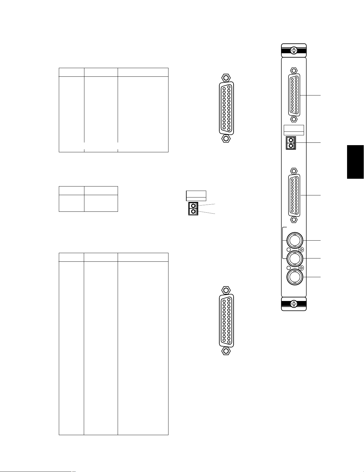
Page 39

-38-
Extension Board
1. EXtension Connector ( 1, 2 )
These connectors are used to expand the Matrix Switcher System. Connect each connector
between the boards that are installed in the WJ-SX550A Matrix Switcher and WJ-AD550
Extension Unit.
2. Data Unit Address Switch (DATA ADDRESS ON/OFF)
These switches are used to identify the unit address number of the WV-PB5548E Data Board
installed in the WJ-AD550 Extension Unit. Select the switches on the board that is installed in
the WJ-SX550A Matrix Switcher, to the “ON” position to meet the Data Board Number.
3. WJ-SX550A Indicator (WJ-SX550A)
This indicator lights up if the board is installed in the WJ-SX550A Matrix Switcher after making
switch setting.
4. WJ-AD550 Indicator (WJ-AD550)
This indicator lights up if the board is installed in the WJ-AD550 Extension Unit after making
switch setting.
Extension
1
2
DATA
ADDRESS
1
2
3
4
5
6
7
8
ON OFF
WJ-SX550A
WJ-AD550
q
w
q
e
r
3
Page 40

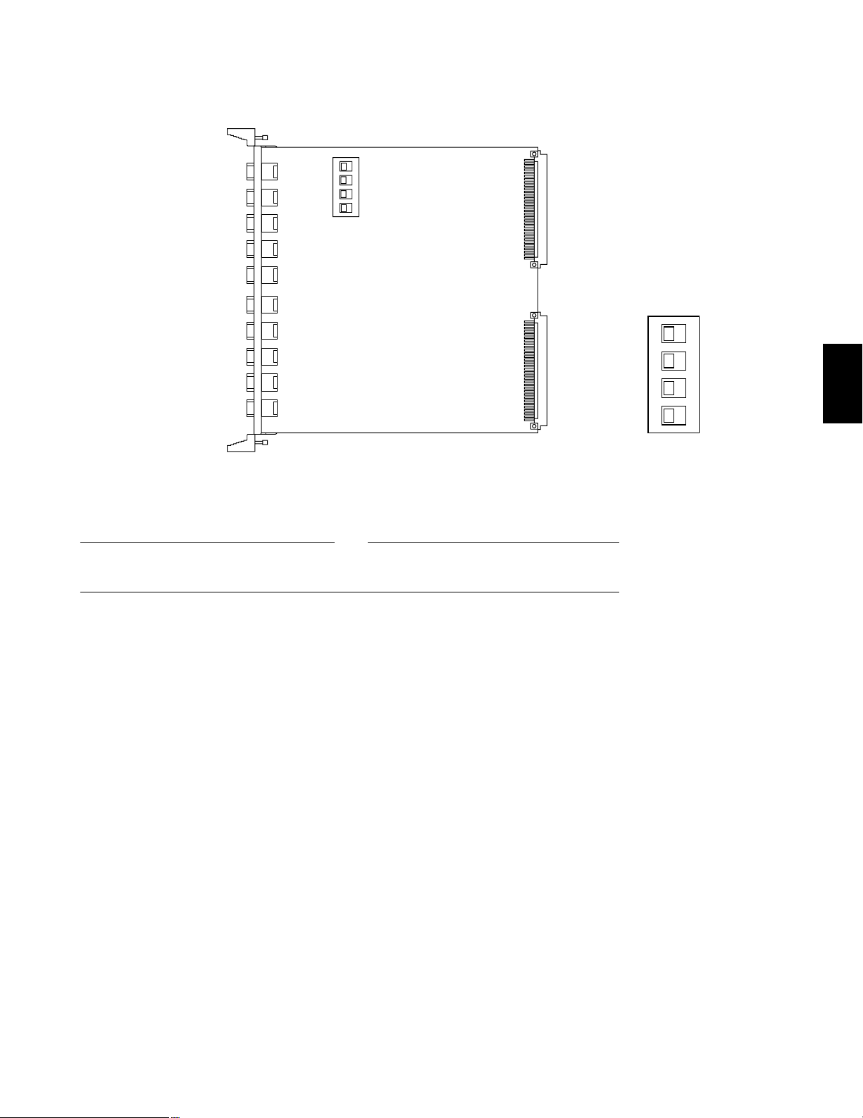
-39-
■ Extension Board Switch Setting
SW1
AD550SX550A
SW3
AD550SX550A
1. Set switches (SW1/SW3) on the board to choose the
system requirement as shown below.
SX550A: Select this position if the board is installed in
the WJ-SX550A Matrix Switcher.
AD550: Select this position if the board is installed in
the WJ-AD550 Extension Unit.
SW1
AD550SX550A
SW3
AD550SX550A
SW1
AD550SX550A
SW3
AD550SX550A
2. Set the Data Unit Address Switch on the board to
meet the WV-PB5548E Data Boards as shown below.
1) The board installed in the WJ-SX550A
Set the switches to the “ON” positions to meet the
identification number of the Data Boards where
installed in the WJ-AD550 Extension Unit.
2) The board installed in the WJ-AD550
Always keep these switches in the “OFF” positions in
the field.
33-64
ALARM
TEST
1-32
00
5
RESET
MODE
CPU
RS-232C
TIME
ADJUST IN
COM
PRINTER
OUT
IN
VS/VD
VD
OUT
OFF
+9V
+5V
−
5V
POWER
ON
11A00001
OUT
IN
1
OUT
IN
2
OUT
IN
3
OUT
IN
4
MONITOR
ALARM OUT
RESET OUT
EXT TIMING IN
RECOVER IN
OUTPUT
MONITOR
ALARM OUT
RESET OUT
EXT TIMING IN
RECOVER IN
MONITOR
ALARM OUT
RESET OUT
EXT TIMING IN
RECOVER IN
OUT
IN
1
OUT
IN
2
OUT
IN
3
OUT
IN
4
OUTPUT
OUT
IN
1
OUT
IN
2
OUT
IN
3
OUT
IN
4
OUTPUTCONTROL
DATA 1
DATA 2
DATA 3
DATA 4
DATA 5
DATA 6
DATA 7
DATA 8
TEST 1
TEST 2
33-64
ALARM
TEST
1-32
00
5
RESET
MODE
OUT
IN
1
OUT
IN
2
OUT
IN
3
OUT
IN
4
MONITOR
ALARM OUT
RESET OUT
EXT TIMING IN
RECOVER IN
OUTPUT
Extension
1
2
1
2
3
4
5
6
7
8
ON OFF
WJ-SX550A
WJ-AD550
INPUT
1
2
3
4
5
6
7
8
CAMERA IN
VIDEO OUT1
VIDEO OUT2
INPUT
1
2
3
4
5
6
7
8
CAMERA IN
VIDEO OUT1
VIDEO OUT2
INPUT
1
2
3
4
5
6
7
8
CAMERA IN
VIDEO OUT1
VIDEO OUT2
INPUT
1
2
3
4
5
6
7
8
CAMERA IN
VIDEO OUT1
VIDEO OUT2
INPUT
1
2
3
4
5
6
7
8
CAMERA IN
VIDEO OUT1
VIDEO OUT2
INPUT
1
2
3
4
5
6
7
8
CAMERA IN
VIDEO OUT1
VIDEO OUT2
INPUT
1
2
3
4
5
6
7
8
CAMERA IN
VIDEO OUT1
VIDEO OUT2
INPUT
1
2
3
4
5
6
7
8
CAMERA IN
VIDEO OUT1
VIDEO OUT2
OFF
+9V
+5V
−
5V
POWER
ON
11A00001
OUT
IN
1
OUT
IN
2
OUT
IN
3
OUT
IN
4
MONITOR
ALARM OUT
RESET OUT
EXT TIMING IN
RECOVER IN
OUTPUT
MONITOR
ALARM OUT
RESET OUT
EXT TIMING IN
RECOVER IN
MONITOR
ALARM OUT
RESET OUT
EXT TIMING IN
RECOVER IN
OUT
IN
1
OUT
IN
2
OUT
IN
3
OUT
IN
4
OUTPUT
OUT
IN
1
OUT
IN
2
OUT
IN
3
OUT
IN
4
OUTPUT
OUT
IN
1
OUT
IN
2
OUT
IN
3
OUT
IN
4
MONITOR
ALARM OUT
RESET OUT
EXT TIMING IN
RECOVER IN
OUTPUT
Extension
1
2
DATA
UNIT ADDRESS
1
2
3
4
5
6
7
8
ON OFF
WJ-SX550A
WJ-AD550
INPUT
1
2
3
4
5
6
7
8
CAMERA IN
VIDEO OUT1
VIDEO OUT2
INPUT
1
2
3
4
5
6
7
8
CAMERA IN
VIDEO OUT1
VIDEO OUT2
INPUT
1
2
3
4
5
6
7
8
CAMERA IN
VIDEO OUT1
VIDEO OUT2
INPUT
1
2
3
4
5
6
7
8
CAMERA IN
VIDEO OUT1
VIDEO OUT2
INPUT
1
2
3
4
5
6
7
8
CAMERA IN
VIDEO OUT1
VIDEO OUT2
INPUT
1
2
3
4
5
6
7
8
CAMERA IN
VIDEO OUT1
VIDEO OUT2
DATA
(RS485)
A
T
B
1
A
R
B
G
A
T
B
2
A
R
B
G
A
T
B
3
A
R
B
G
A
T
B
4
A
R
B
G
A
T
B
5
A
R
B
G
A
T
B
6
A
R
B
G
A
T
B
7
A
R
B
G
A
T
B
8
A
R
B
G
DATA
(RS485)
A
T
B
1
A
R
B
G
A
T
B
2
A
R
B
G
A
T
B
3
A
R
B
G
A
T
B
4
A
R
B
G
A
T
B
5
A
R
B
G
A
T
B
6
A
R
B
G
A
T
B
7
A
R
B
G
A
T
B
8
A
R
B
G
DATA
ADDRESS
1
2
3
4
5
6
7
8
ON OFF
DATA
UNIT ADDRESS
DATA
ADDRESS
1
2
3
4
5
6
7
8
ON OFF
Initially, “OFF” positions are selected at the factory.
WJ-AD550 Extension Unit
WJ-SX550A Matrix Switcher
Initially, AD550 positions are selected at the factory.
3
Page 41

ALARM
TEST
1-32
5
RESET
MODE
33-64
-40-
WV-PB5564E Alarm Board
3
2. Mode Selection Switch (MODE)
This rotary switch, in combination with the test switch, is used to select the alarm test mode.
Mode 0: Press the Test Switch to receive, from memory, a chronologically organized display (in
the Alarm Number Display) of all alarms received from the Alarm Input Connector.
Mode 1: Press the Test Switch to simulate receiving alarm inputs 1-64 in ascending order, one
alarm per second. Use this mode to test the system for Alarm Mode-1, Mode-2 or Mode-3
set up.
Mode 2: Press the Test Switch to simulate receiving alarm inputs 1-64 all at the same time. Use
this mode to test the system for Alarm Mode-1, Mode-2 or Mode-3 set up.
Mode 3-9: These modes are not available.
Note: The alarm inputs 65-128 are activated above modes if the SW1 on the board is set at
alarm number 65-128. Refer to the Dip Switch Setting on page 42.
3. Test Switch (TEST)
This switch is used to run the alarm test mode in combination with the Mode Selection Switch.
4. Reset Switch (RESET)
This switch is used to stop the alarm test mode or clear alarm the records from the internal
memory.
q
w
e
r
t
1. Alarm Number display
This display indicates the alarm input number when the associated alarm sensor unit is activated.
Note: The display indicator lights up as shown below when the alarm number is over one hun-
dred.
indicator
Page 42

1
2
3
4
5
6
7
8
9
10
11
12
13
14
15
16
17
18
19
Alarm 1
Alarm 2
Alarm 3
Alarm 4
Alarm 5
Alarm 6
Alarm 7
Alarm 8
Alarm 9
Alarm 10
Alarm 11
Alarm 12
Alarm 13
Alarm 14
Alarm 15
Alarm 16
Alarm 17
Alarm 18
Alarm 19
Alarm 65
Alarm 66
Alarm 67
Alarm 68
Alarm 69
Alarm 70
Alarm 71
Alarm 72
Alarm 73
Alarm 74
Alarm 75
Alarm 76
Alarm 77
Alarm78
Alarm 79
Alarm 80
Alarm 81
Alarm 82
Alarm 83
20
21
22
23
24
25
26
27
28
29
30
31
32
33
34
35
36
37
Alarm 20
Alarm 21
Alarm 22
Alarm 23
Alarm 24
Alarm 25
Alarm 26
Alarm 27
Alarm 28
Alarm 29
Alarm 30
Alarm 31
Alarm 32
Not used
Not used
Not used
Ground
Ground
Alarm 84
Alarm 85
Alarm 86
Alarm 87
Alarm 88
Alarm 89
Alarm 90
Alarm 91
Alarm 92
Alarm 93
Alarm 94
Alarm 95
Alarm 96
Not used
Not used
Not used
Ground
Ground
Pin No.
Designation
Pin No.
Designation
Board No.1 Board No.2 Board No.1 Board No.2
1
2
3
4
5
6
7
8
9
10
11
12
13
14
15
16
17
18
19
Alarm 33
Alarm 34
Alarm 35
Alarm 36
Alarm 37
Alarm 38
Alarm 39
Alarm 40
Alarm 41
Alarm 42
Alarm 43
Alarm 44
Alarm 45
Alarm 46
Alarm 47
Alarm 48
Alarm 49
Alarm 50
Alarm 51
Alarm 97
Alarm 98
Alarm 99
Alarm 100
Alarm 101
Alarm 102
Alarm 103
Alarm 104
Alarm 105
Alarm 106
Alarm 107
Alarm 108
Alarm 109
Alarm 110
Alarm 111
Alarm 112
Alarm 113
Alarm 114
Alarm 115
20
21
22
23
24
25
26
27
28
29
30
31
32
33
34
35
36
37
Alarm 116
Alarm 117
Alarm 118
Alarm 119
Alarm 120
Alarm 121
Alarm 122
Alarm 123
Alarm 124
Alarm 125
Alarm 126
Alarm 127
Alarm 128
Not used
Not used
Not used
Ground
Ground
Pin No.
Designation
Pin No.
Designation
Board No.1 Board No.2 Board No.1 Board No.2
Alarm 52
Alarm 53
Alarm 54
Alarm 55
Alarm 56
Alarm 57
Alarm 58
Alarm 59
Alarm 60
Alarm 61
Alarm 62
Alarm 63
Alarm 64
Not used
Not used
Not used
Ground
Ground
-41-
(Close) Alarm Sensor(Open) Alarm Sensor
Normal Condition Alarm In Alarm Signal
Normally Open
(NOR OPEN)
Normally Closed
(NOR CLOSE)
(Close) Alarm Sensor (Open) Alarm Sensor
t
0V
0V
t
5. Alarm Input Connector (1-32, 33-64)
This connector accepts the alarm signals, either normally open or normally closed, from the
associated alarm sensor unit.
3
t 100 ms
>
t 100 ms
>
1-32
37
20
19
1
33-64
37
20
19
1
Page 43

65-72
73-80
81-88
89-96
97-104
105-112
113-120
121-128
-42-
3. Confirm switchers (SW12) on the board are set to the following positions.
12
OFF
SW12
These switches are used only for factory test.
Always keep these switches in the "OFF" positions in the field.
Note
2. Set switches (SW4 - SW11) on the board to meet the
alarm input requirements. Initially, normally open
(NOR, OPEN) positions are selected at the factory.
12345678
OFF
SW4
NOR
CLOSE
NOR
OPEN
1
12345678
OFF
SW5
2
1
2
3
4
5
6
7
8
SW4
SW5
SW6
SW7
SW8
SW9
SW10
SW11
Switch No.
1 - 8
9 - 16
17 - 24
25 - 32
33 - 40
41 - 48
49 - 56
57 - 64
Alarm Input
Board No.1 Board No.2
■ WV-PB5564E Alarm Board Dip Switch
Setting
1. Set switches (SW1) on the board to meet the alarm
input number as shown below.
BOARD
NO.
12
OFF
12
OFF
1
2
1-64
65-128
ALARM
INPUT NO.
SW1 SETTING
1
2
OFF
SW1
UNIT ADR
3
1
SW4
2
SW5
3
SW6
OFF
12
SW1
UNIT ADR
OFF
12
4
SW7
5
SW8
6
SW9
7
SW10
SW12
8
SW11
Page 44

-43-
WV-PB5548E Data Board
1. Data Connector (TA/TB/RA/RB/GND, 1 - 8)
These connectors are used to transmit/receive control data to/from the camera site. Use data
grade cable, suitable for RS-485 (shielded, twisted pairs). Cable length may be extended up to
1,200 m (4,000 ft).
TB
RA (+)
RB
GND
RT
TA (+)
S W
1
DATA
(RS485)
A
T
B
1
A
R
B
G
A
T
B
2
A
R
B
G
A
T
B
3
A
R
B
G
A
T
B
4
A
R
B
G
A
T
B
5
A
R
B
G
A
T
B
6
A
R
B
G
A
T
B
7
A
R
B
G
A
T
B
8
A
R
B
G
RT: Termination Resistor, 150Ω 1/2W
SW: Selection Switch, Full Duplex/ Half Duplex
GND: Ground; Connected to each channel and
common ground.
3
Page 45

-44-
■ WV-PB5548E Data Board Dip Switch Setting
1234
OFF
SW1
1234
OFF
SW3
SW100
SW150
SW200
SW250
SW300
SW350
SW400
SW450
SW5
SW6
BOARD
NO.
1234
OFF
1234
OFF
1234
OFF
1234
OFF
1234
OFF
1234
OFF
1234
OFF
1234
OFF
1
2
3
4
5
6
7
8
SW1 SETTING
1. Set switches (SW1) on the board to meet the data
board number as shown in the following table.
Initially, board number 1 is selected at the factory.
2. Set switches (SW100/SW150/SW200/SW250/SW300/
SW350/SW400/SW450) on the board to choose the
communication lines as either Full Duplex (FULL) or
Half Duplex (HALF).
Initially, Full Duplex(FULL) positions are selected at
the factory.
3. Set switch (SW5) on the board to choose the LED indicator as either “ON” or “OFF” mode. The indicator displays that the control data are activated normally on
the board.
Initially, “ON” position is selected at the factory.
4. Confirm switches (SW3/SW6) on the board are set to
the following positions.
SW100 - SW450
FULL
HALF
SW5
ON
OFF
LED
1234
OFF
SW3
SW6
12PROG
Full: 4 Lines
Half: 2 Lines
These switches are used only for factory test.
Always keep these switches in these positions in the
field.
Note
3
Page 46

-45-
BOARD SELECTION FOR SYSTEM EXPANSION
This switcher has 15 slots, clever of which are available for system expansion.
The CPU and Control Board, along with one Video Input Board and one Video Output Board are supplied as standard accessories.
Depending on the number of camera inputs and monitor outputs required, additional WV-PB5508E Video Input Boards, WVPB5504AE Video Output Boards will be required.
OFF
+9V
+5V
−5V
POWER
ON
11A00001
INPUTCPU
1
2
3
4
5
6
7
8
CAMERA IN
VIDEO OUT1
VIDEO OUT2
RS-232C
TIME
ADJUST IN
COM
PRINTER
OUT
IN
VS/VD
VD
OUT
54321 6 7 8 9 10 11 12 13 14 15
CONTROL
DATA 1
DATA 2
DATA 3
DATA 4
DATA 5
DATA 6
DATA 7
DATA 8
TEST 1
TEST 2
OUT
IN
1
OUT
IN
2
OUT
IN
3
OUT
IN
4
MONITOR
ALARM OUT
RESET OUT
EXT TIMING IN
RECOVER IN
OUTPUT
3
Also the extension unit has 15 slots and two Extension Boards are installed in this unit.
• WJ-AD550 Extension Unit
• WJ-SX550A Matrix Switcher
OFF
+9V
+5V
−5V
POWER
ON
11A00001
Extension
1
2
WJ-SX550A
Extension
1
2
DATA
ADDRESS
1
2
3
4
5
6
7
8
ON OFF
DATA
ADDRESS
1
2
3
4
5
6
7
8
ON OFF
WJ-AD550
WJ-SX550A
WJ-AD550
54321 6789101112131415
Page 47

Cameras
Cameras
-46-
1 - 8
9 - 16
17 - 24
25 - 32
33 - 40
41 - 48
49 - 56
57 - 64
1 - 4
1 - 4
1 - 4
1 - 4
1 - 4
1 - 4
1 - 4
1 - 4
not required
not required
not required
not required
not required
not required
not required
not required
1
1
1
1
1
1
1
1
4
5
6
7
8
9
10
11
11
10
9
8
7
6
5
4
Monitors
Extension Unit
WJ-AD550
Output Boards
WV-PB5504AE
1
2
3
4
5
6
7
8
65 - 72 1 - 4 required 2 15 159
73 - 80 1 - 4 required 2 16 1410
81 - 88 1 - 4 required 2 17 1311
89 - 96 1 - 4 required 2 18 1212
97 - 104 1 - 4 required 2 19 1113
105 - 112 1 - 4 required 2 20 1014
113 - 120 1 - 4 required 2 21 915
121 - 128 1 - 4 required 2 22 816
Input Boards
WV-PB5508E
Slots Used Slots Left
3
The following table shows components required for various system configurations.
1 - 8
9 - 16
17 - 24
25 - 32
33 - 40
41 - 48
49 - 56
57 - 64
5 - 8
5 - 8
5 - 8
5 - 8
5 - 8
5 - 8
5 - 8
5 - 8
not required
not required
not required
not required
not required
not required
not required
not required
2
2
2
2
2
2
2
2
5
6
7
8
9
10
11
12
10
9
8
7
6
5
4
3
Monitors
Extension Unit
WJ-AD550
Output Boards
WV-PB5504AE
1
2
3
4
5
6
7
8
65 - 72 5 - 8 required 4 17 139
73 - 80 5 - 8 required 4 18 1210
81 - 88 5 - 8 required 4 19 1111
89 - 96 5 - 8 required 4 20 1012
97 - 104 5 - 8 required 4 21 913
105 - 112 5 - 8 required 4 22 814
113 - 120 5 - 8 required 4 23 715
121 - 128 5 - 8 required 4 24 616
Input Boards
WV-PB5508E
Slots Used Slots Left
Page 48

-47-
Cameras
1 - 8
9 - 16
17 - 24
25 - 32
33 - 40
41 - 48
49 - 56
57 - 64
9 - 12
9 - 12
9 - 12
9 - 12
9 - 12
9 - 12
9 - 12
9 - 12
not required
not required
not required
not required
not required
not required
not required
not required
3
3
3
3
3
3
3
3
6
7
8
9
10
11
12
13
9
8
7
6
5
4
3
2
Monitors
Extension Unit
WJ-AD550
Output Boards
WV-PB5504AE
1
2
3
4
5
6
7
8
65 - 72 9 - 12 required 6 19 119
73 - 80 9 - 12 required 6 20 1010
81 - 88 9 - 12 required 6 21 911
89 - 96 9 - 12 required 6 22 812
97 - 104 9 - 12 required 6 23 713
105 - 112 9 - 12 required 6 24 614
113 - 120 9 - 12 required 6 25 515
121 - 128 9 - 12 required 6 26 416
Input Boards
WV-PB5508E
Slots Used Slots Left
Cameras
1 - 8
9 - 16
17 - 24
25 - 32
33 - 40
41 - 48
49 - 56
57 - 64
9 - 12
9 - 12
9 - 12
9 - 12
9 - 12
9 - 12
9 - 12
9 - 12
not required
not required
not required
not required
not required
not required
not required
not required
4
4
4
4
4
4
4
4
7
8
9
10
11
12
13
14
8
7
6
5
4
3
2
1
Monitors
Extension Unit
WJ-AD550
Output Boards
WV-PB5504AE
1
2
3
4
5
6
7
8
65 - 72 9 - 12 required 8 21 99
73 - 80 9 - 12 required 8 22 810
81 - 88 9 - 12 required 8 23 711
89 - 96 9 - 12 required 8 24 612
97 - 104 9 - 12 required 8 25 513
105 - 112 9 - 12 required 8 26 414
113 - 120 9 - 12 required 8 27 315
121 - 128 9 - 12 required 8 28 216
Input Boards
WV-PB5508E
Slots Used Slots Left
Notes:
• The two extension boards should be installed in the slots when the extension unit is required.
• It will be installed up to two (2) Alarm Boards or eight (8) Data Boards in the slots left.
3
Page 49

-49-
INSTALLATION
AND
SYSTEM
CONNECTIONS
4
Page 50

-50-
4
INSTALLATION
The installation described below should be made by qualified service personnel or system installers.
■ WV-CU550A System Controller
Replacing the Side Panels with the optional
WV-Q62E Rack Angle Bracket
1. Remove both the left and right side panels of the
System Controller by removing four screws.
■ WJ-SX550A Matrix Switcher
Mounting into the Rack
1. Remove four rubber feet by removing four screws on
the bottom of the Matrix Switcher.
2. Remove the Palm-rest located on the front of the
System Controller by removing two screws.
3. Place the Rack Angle Brackets on both sides of the
System Controller and tighten with the four supplied
screws.
4. Install the System Controller with Rack Angle Brackets
in the rack by using four screws (procured locally).
Remove screws.
Tighten
screws.
Rack Angle Bracket
Side Panel
Rack Mount Screws
Rack Mount Screws
Palm-rest
• Do not block the ventilation opening or slots on the cover to prevent the unit from rising temperature.
Always keep the temperature in the rack within 50°C (122°F)
• Secure the rear of the unit to the rack by using the additional mounting angles (procured locally) when the vibration is
added to the rack.
Caution
2. Install the Matrix Switcher in the rack by using eight
screws (procured locally).
Note:
The cooling fans inside the Matrix Switcher are
article of consumption, and need to replace periodically.
Remove Screws
Rubber
feet
Rack Mount Screws
Rubber
feet
Page 51

-51-
1. Remove the screws from the rear panel(s) of the
Matrix Switcher.
2. Remove the rear panel(s).
3. Place the Board into the desired position in the rear of
Matrix Switcher by sliding it inside the board guides.
■ Installing Additional Boards for Expansion
Before installing any boards be sure to turn off the
Power Switch of the WJ-SX550A Matrix Switcher.
Caution
Each slot is identical, so the board can installed in any
slot.
However it is recommended to install the boards as
shown below for an orderly installation.
Note
4. Make sure to push in the Board until it is seated firmly.
5. Secure the Board by tightening the two screws
on the board.
6. Close off open spaces on the rear of the Matrix
Switcher by using WV-Q63E Blank Panels
(Optional) or supplied rear panel(s).
Rear Panel
Remove four
screws.
Blank Panel
Tighten screws.
Tighten screws.
Board
CPU
RS-232C
TIME
ADJUST IN
COM
PRINTER
OUT
IN
VS/VD
VD
OUT
OFF
+9V
+5V
−5V
POWER
ON
11A00001
INPUT
1
2
3
4
5
6
7
8
CAMERA IN
VIDEO OUT1
VIDEO OUT2
INPUT
1
2
3
4
5
6
7
8
CAMERA IN
VIDEO OUT1
VIDEO OUT2
INPUT
1
2
3
4
5
6
7
8
CAMERA IN
VIDEO OUT1
VIDEO OUT2
INPUT
1
2
3
4
5
6
7
8
CAMERA IN
VIDEO OUT1
VIDEO OUT2
INPUT
1
2
3
4
5
6
7
8
CAMERA IN
VIDEO OUT1
VIDEO OUT2
INPUT
1
2
3
4
5
6
7
8
CAMERA IN
VIDEO OUT1
VIDEO OUT2
INPUT
1
2
3
4
5
6
7
8
CAMERA IN
VIDEO OUT1
VIDEO OUT2
INPUT
1
2
3
4
5
6
7
8
CAMERA IN
VIDEO OUT1
VIDEO OUT2
33-64
ALARM
TEST
1-32
00
5
RESET
MODE
CONTROL
DATA 1
DATA 2
DATA 3
DATA 4
DATA 5
DATA 6
DATA 7
DATA 8
TEST 1
TEST 2
OUT
IN
1
OUT
IN
2
OUT
IN
3
OUT
IN
4
MONITOR
ALARM OUT
RESET OUT
EXT TIMING IN
RECOVER IN
OUTPUT
OUT
IN
1
OUT
IN
2
OUT
IN
3
OUT
IN
4
MONITOR
ALARM OUT
RESET OUT
EXT TIMING IN
RECOVER IN
OUTPUT
OUT
IN
1
OUT
IN
2
OUT
IN
3
OUT
IN
4
MONITOR
ALARM OUT
RESET OUT
EXT TIMING IN
RECOVER IN
OUTPUT
OUT
IN
1
OUT
IN
2
OUT
IN
3
OUT
IN
4
MONITOR
ALARM OUT
RESET OUT
EXT TIMING IN
RECOVER IN
OUTPUT
Alarm Board
Video Input Board Video Output
Board
4
• Extension Unit is not required.
or
Page 52

-52-
• Extension Unit is required
When the Extension Unit is required to install the boards, it
is recommended to install the boards as shown below.
Removing Extension Boards
1. Remove the screws from rear panel(s) of the
Extension Unit.
2. Remove the rear panel(s).
3. Loosen the two screws on the Extension Board(s).
4. Pull out the Extension Board(s) from the rear of
Extension Unit by sliding it inside the board guides.
Installing Boards
1. Install a Extension Board to the slot number 15 of the
Matrix Switcher and Extension Unit.
Note: Before installing the boards, be sure to set the dip
switches to the required positions.
2. Install the Video Input Boards as shown below.
Board Number 1 - 8 are into the Matrix Switcher
Board Number 9 - 16 are into the Extension Unit.
3. Install the Video Output Boards as shown below.
Board Number 1 - 4 are into the Matrix Switcher.
Board Number 5 - 8 are into the Extension Unit.
Note: Up to two Alarm Boards or eight Data Boards can
be installed in the Matrix Switcher and Extension Unit.
When the Data Boards are installed in the Extension
Unit, be sure to set the Data Unit Address Switch on
the Extension Boards.
33-64
ALARM
TEST
1-32
00
5
RESET
MODE
CPU
RS-232C
TIME
ADJUST IN
COM
PRINTER
OUT
IN
VS/VD
VD
OUT
OFF
+9V
+5V
−
5V
POWER
ON
11A00001
OUT
IN
1
OUT
IN
2
OUT
IN
3
OUT
IN
4
MONITOR
ALARM OUT
RESET OUT
EXT TIMING IN
RECOVER IN
OUTPUT
MONITOR
ALARM OUT
RESET OUT
EXT TIMING IN
RECOVER IN
MONITOR
ALARM OUT
RESET OUT
EXT TIMING IN
RECOVER IN
OUT
IN
1
OUT
IN
2
OUT
IN
3
OUT
IN
4
OUTPUT
OUT
IN
1
OUT
IN
2
OUT
IN
3
OUT
IN
4
OUTPUTCONTROL
DATA 1
DATA 2
DATA 3
DATA 4
DATA 5
DATA 6
DATA 7
DATA 8
TEST 1
TEST 2
33-64
ALARM
TEST
1-32
00
5
RESET
MODE
OUT
IN
1
OUT
IN
2
OUT
IN
3
OUT
IN
4
MONITOR
ALARM OUT
RESET OUT
EXT TIMING IN
RECOVER IN
OUTPUT
Extension
1
2
DATA
ADDRESS
1
2
3
4
5
6
7
8
ON OFF
WJ-SX550A
WJ-AD550
INPUT
1
2
3
4
5
6
7
8
CAMERA IN
VIDEO OUT1
VIDEO OUT2
INPUT
1
2
3
4
5
6
7
8
CAMERA IN
VIDEO OUT1
VIDEO OUT2
INPUT
1
2
3
4
5
6
7
8
CAMERA IN
VIDEO OUT1
VIDEO OUT2
INPUT
1
2
3
4
5
6
7
8
CAMERA IN
VIDEO OUT1
VIDEO OUT2
INPUT
1
2
3
4
5
6
7
8
CAMERA IN
VIDEO OUT1
VIDEO OUT2
INPUT
1
2
3
4
5
6
7
8
CAMERA IN
VIDEO OUT1
VIDEO OUT2
INPUT
1
2
3
4
5
6
7
8
CAMERA IN
VIDEO OUT1
VIDEO OUT2
INPUT
1
2
3
4
5
6
7
8
CAMERA IN
VIDEO OUT1
VIDEO OUT2
OFF
+9V
+5V
−
5V
POWER
ON
11A00001
OUT
IN
1
OUT
IN
2
OUT
IN
3
OUT
IN
4
MONITOR
ALARM OUT
RESET OUT
EXT TIMING IN
RECOVER IN
OUTPUT
MONITOR
ALARM OUT
RESET OUT
EXT TIMING IN
RECOVER IN
MONITOR
ALARM OUT
RESET OUT
EXT TIMING IN
RECOVER IN
OUT
IN
1
OUT
IN
2
OUT
IN
3
OUT
IN
4
OUTPUT
OUT
IN
1
OUT
IN
2
OUT
IN
3
OUT
IN
4
OUTPUT
OUT
IN
1
OUT
IN
2
OUT
IN
3
OUT
IN
4
MONITOR
ALARM OUT
RESET OUT
EXT TIMING IN
RECOVER IN
OUTPUT
Extension
1
2
DATA
ADDRESS
1
2
3
4
5
6
7
8
ON OFF
WJ-SX550A
WJ-AD550
INPUT
1
2
3
4
5
6
7
8
CAMERA IN
VIDEO OUT1
VIDEO OUT2
INPUT
1
2
3
4
5
6
7
8
CAMERA IN
VIDEO OUT1
VIDEO OUT2
INPUT
1
2
3
4
5
6
7
8
CAMERA IN
VIDEO OUT1
VIDEO OUT2
INPUT
1
2
3
4
5
6
7
8
CAMERA IN
VIDEO OUT1
VIDEO OUT2
INPUT
1
2
3
4
5
6
7
8
CAMERA IN
VIDEO OUT1
VIDEO OUT2
INPUT
1
2
3
4
5
6
7
8
CAMERA IN
VIDEO OUT1
VIDEO OUT2
INPUT
1
2
3
4
5
6
7
8
CAMERA IN
VIDEO OUT1
VIDEO OUT2
INPUT
1
2
3
4
5
6
7
8
CAMERA IN
VIDEO OUT1
VIDEO OUT2
WJ-AD550 Extension Unit
WJ-SX550A Matrix Switcher
Video Input Board
(Board #1-8)
Video Output
Board
(Board #1-4)
Extension
Board
Video Input Board
(Board #9-16)
Video Output
Board
(Board #5-8)
Extension
Board
Alarm
Board
Remove screws.
Loosen two screws
Before installing any boards, be sure to turn off the
Power Switch of the WJ-SX550A Matrix Switcher and
WJ-AD550 Extension Unit.
Caution
4
Page 53

-53-
SYSTEM CONNECTIONS
Over View of System Connection
TL TL
TL TL
CPU
RS-232C
TIME
ADJUST IN
COM
PRINTER
OUT
IN
VS/VD
VD
OUT
OFF
+9V
+5V
−
5V
POWER
ON
11A00001
OUT
IN
1
OUT
IN
2
OUT
IN
3
OUT
IN
4
MONITOR
ALARM OUT
RESET OUT
EXT TIMING IN
RECOVER IN
OUTPUT
MONITOR
ALARM OUT
RESET OUT
EXT TIMING IN
RECOVER IN
MONITOR
ALARM OUT
RESET OUT
EXT TIMING IN
RECOVER IN
OUT
IN
1
OUT
IN
2
OUT
IN
3
OUT
IN
4
OUTPUT
OUT
IN
1
OUT
IN
2
OUT
IN
3
OUT
IN
4
OUTPUTCONTROL
DATA 1
DATA 2
DATA 3
DATA 4
DATA 5
DATA 6
DATA 7
DATA 8
TEST 1
TEST 2
OUT
IN
1
OUT
IN
2
OUT
IN
3
OUT
IN
4
MONITOR
ALARM OUT
RESET OUT
EXT TIMING IN
RECOVER IN
OUTPUT
Extension
1
2
1
2
3
4
5
6
7
8
ON OFF
WJ-SX550A
WJ-AD550
INPUT
1
2
3
4
5
6
7
8
CAMERA IN
VIDEO OUT1
VIDEO OUT2
INPUT
1
2
3
4
5
6
7
8
CAMERA IN
VIDEO OUT1
VIDEO OUT2
INPUT
1
2
3
4
5
6
7
8
CAMERA IN
VIDEO OUT1
VIDEO OUT2
INPUT
1
2
3
4
5
6
7
8
CAMERA IN
VIDEO OUT1
VIDEO OUT2
INPUT
1
2
3
4
5
6
7
8
CAMERA IN
VIDEO OUT1
VIDEO OUT2
INPUT
1
2
3
4
5
6
7
8
CAMERA IN
VIDEO OUT1
VIDEO OUT2
INPUT
1
2
3
4
5
6
7
8
CAMERA IN
VIDEO OUT1
VIDEO OUT2
INPUT
1
2
3
4
5
6
7
8
CAMERA IN
VIDEO OUT1
VIDEO OUT2
DATA
UNIT ADDRESS
33-64
ALARM
TEST
1-32
00
5
RESET
MODE
33-64
ALARM
TEST
1-32
00
5
RESET
MODE
OFF
+9V
+5V
−
5V
POWER
ON
11A00001
OUT
IN
1
OUT
IN
2
OUT
IN
3
OUT
IN
4
MONITOR
ALARM OUT
RESET OUT
EXT TIMING IN
RECOVER IN
OUTPUT
MONITOR
ALARM OUT
RESET OUT
EXT TIMING IN
RECOVER IN
MONITOR
ALARM OUT
RESET OUT
EXT TIMING IN
RECOVER IN
OUT
IN
1
OUT
IN
2
OUT
IN
3
OUT
IN
4
OUTPUT
OUT
IN
1
OUT
IN
2
OUT
IN
3
OUT
IN
4
OUTPUT
OUT
IN
1
OUT
IN
2
OUT
IN
3
OUT
IN
4
MONITOR
ALARM OUT
RESET OUT
EXT TIMING IN
RECOVER IN
OUTPUT
Extension
1
2
DATA
UNIT ADDRESS
1
2
3
4
5
6
7
8
ON OFF
WJ-SX550A
WJ-AD550
INPUT
1
2
3
4
5
6
7
8
CAMERA IN
VIDEO OUT1
VIDEO OUT2
INPUT
1
2
3
4
5
6
7
8
CAMERA IN
VIDEO OUT1
VIDEO OUT2
INPUT
1
2
3
4
5
6
7
8
CAMERA IN
VIDEO OUT1
VIDEO OUT2
INPUT
1
2
3
4
5
6
7
8
CAMERA IN
VIDEO OUT1
VIDEO OUT2
INPUT
1
2
3
4
5
6
7
8
CAMERA IN
VIDEO OUT1
VIDEO OUT2
INPUT
1
2
3
4
5
6
7
8
CAMERA IN
VIDEO OUT1
VIDEO OUT2
1
2
3
4
5
6
7
8
INPUT
1
2
3
4
5
6
7
8
CAMERA IN
VIDEO OUT1
VIDEO OUT2
INPUT
1
2
3
4
5
6
7
8
CAMERA IN
VIDEO OUT1
VIDEO OUT2
Alarm Sensor
Printer
WV-CU550A System Controller (Max 8 Controller)
Max 16 Monitors
Computer
RS-232C Port
WJ-SX550A
Matrix Switcher
Combination Camera
Max. 128 cameras
WJ-AD550
Extension Unit
VTR
System Status
Monitor
Receive
Receiver
Note : Refer to the Operating Instruction of WJ-AD550 Extension Unit for connections when the WJ-AD550 Extension Unit is used.
4
Page 54

-54-
■ Connection with the Camera Sites
Connect the Camera Site Equipments to the Camera
Input Connectors (CAMERA IN, 1-8) on the Video
Input Board.
Caution: Make sure that the cable length between the
camera site and the WJ-SX550A Matrix Switcher
is less than 1,200m (4,000 ft) when using 5C - 2V
coaxial cable or equivalent.
Connection with the Camera Sites
INPUT
1
2
3
4
5
6
7
8
CAMERA IN
VIDEO OUT1
VIDEO OUT2
Camera 1 - 4
Camera 5 - 8
Video Input Board
WV-CA64
(VIDEO ACTIVE LOOP THROUGH OUT)
WV-CA64 (VIDEO ACTIVE LOOP THROUGH OUT)
WV-7140/WV-7141 WV-7140/WV-7141
WV-7225 WV-7260D WV-7260D
WV-RC100 WV-RC150
AUX
Alarm
WV-RC150
AUX
Alarm
AUX
Alarm
4
Page 55

-55-
■ Connection with the Monitors
Connect the Monitors to the Monitor Output Connectors (MONITOR OUT) on the Video Output Board(s).
TL
TL
TL
TL
2 4 6 8 10 12 14 16
ALARM
IN
1
COM2
ALARM
RESET IN
3
ALARM
RECOVER OUT
4
ALARM
OUT
5
1 SHOT IN6
7
TAPE END
OUT
8
WARNING
OUT
9
HUMID OUT10
REC OUT11
REC REVIEW
OUT
12
SERIES
REC IN
13
14
TIME
ADJUST IN
15
TIME
ADJUST OUT
16
COM
SERIES
REC OUT
13579111315
OUT
IN
OUT
IN
OUT
IN
OUT
IN
MONITOR
ALARM OUT
RESET OUT
EXT TIMING IN
RECOVER IN
OUTPUT
1
2
3
4
Connection with the Monitors
Video Output Board
Monitor
Monitor
Monitor
Monitor
CAMERA
SW OUT
VTR
4
Page 56

-56-
■ Connection with the System Controllers
• Data Line and Unit Number Setting
Up to eight WV-CU550A System Controllers may be
installed in a Matrix System.
The Control Board installed in the WJ-SX550A Matrix
Switcher has eight ports that correspond to eight WVCU550A System Controller inputs.
If the supplied 6-conductor cable assembly is used,
simply plug one end of the cable into a port on the
Control Board and other end into one of the ports on
the rear of the System Controller.
• Mode Selection Switch Setting
The Mode Selection Switch, that selects the operation
mode of the System Controller, is located on the rear
of the System Controller Select the switches to meet
the system shown below.
If the cable to be used is assembled from locally procured materials it is important that only high quality,
data grade cable, suitable for RS-485 (2 shield, twisted pairs) is used.
Low grade cable will result in unstable operation of the
system.
4
Normal Mode: Selects the menus except the CAM-P
(D5) Menu on the LCD.
CAM-P Mode: Selects the CAM-P (D5) Menu on the
LCD included menus at the Normal Mode. Select
this mode if operating the Camera Position functions.
Select the mode before turning the System Controller
power on.
The selected mode is fixed to turn the System
Controller power on. Initially, Normal Mode is selected
at the factory.
Normal Mode
OFF
MODE
ON
CAM-P Mode
OFF
MODE
ON
Page 57

-57-
IN OUT
TERM
ON OFF
DATA
0
1
2
3
4
5
6
7
8
9
CONTROLLER
UNIT NO.
1-8
Controller 1
IN OUT
TERM
ON OFF
DATA
0
1
2
3
4
5
6
7
8
9
CONTROLLER
UNIT NO.
1-8
Controller 2
IN OUT
TERM
ON OFF
DATA
0
1
2
3
4
5
6
7
8
9
CONTROLLER
UNIT NO.
1-8
Controller 3
IN OUT
TERM
ON OFF
DATA
0
1
2
3
4
5
6
7
8
9
CONTROLLER
UNIT NO.
1-8
Controller 4
IN OUT
TERM
ON OFF
DATA
0
1
2
3
4
5
6
7
8
9
CONTROLLER
UNIT NO.
1-8
Controller 5
IN OUT
TERM
ON OFF
DATA
0
1
2
3
4
5
6
7
8
9
CONTROLLER
UNIT NO.
1-8
Controller 6
IN OUT
TERM
ON OFF
DATA
0
1
2
3
4
5
6
7
8
9
CONTROLLER
UNIT NO.
1-8
Controller 7
IN OUT
TERM
ON OFF
DATA
0
1
2
3
4
5
6
7
8
9
CONTROLLER
UNIT NO.
1-8
Controller 8
Control Board
Matrix Switcher WJ-SX550A
CONTROL
DATA 1
DATA 2
DATA 3
DATA 4
DATA 5
DATA 6
DATA 7
DATA 8
TEST 1
TEST 2
ON
Termination
Switch
Controller 1 ON
ON
ON
ON
ON
ON
ON
Any Number 1-8
Any Number 1-8
Any Number 1-8
Any Number 1-8
Any Number 1-8
Any Number 1-8
Any Number 1-8
Any Number 1-8
Controller 2
Controller 3
Controller 4
Controller 5
Controller 6
Controller 7
Controller 8
Controller
Unit Number
Home Run Connections
Termination and Controller Unit Number Setting
• Direct connection between the Control Board and System Controllers (“Home Run” Type Wiring)
In this type of installation there is one control cable directly connecting each System Controller to one Control Board port.
Refer to the connections and controller settings shown below.
4
Note: Do not use the "0" or "9" controller unit numbers.
Page 58

-58-
• Indirect connection between the Control Board and System Controllers (“Daisy-Chain” Type Wiring)
In this type of installation only one control cable directly connects between System Controller #1 and the Control Board. The
rest of the System Controllers connect to System Controller #1 in a Daisy-Chain type of connection. Refer to the connections
and controller settings shown below.
IN OUT
TERM
ON OFF
DATA
0
1
2
3
4
5
6
7
8
9
CONTROLLER
UNIT NO.
1-8
Controller 1
IN OUT
TERM
ON OFF
DATA
0
1
2
3
4
5
6
7
8
9
CONTROLLER
UNIT NO.
1-8
Controller 2
IN OUT
TERM
ON OFF
DATA
0
1
2
3
4
5
6
7
8
9
CONTROLLER
UNIT NO.
1-8
Controller 3
IN OUT
TERM
ON OFF
DATA
0
1
2
3
4
5
6
7
8
9
CONTROLLER
UNIT NO.
1-8
Controller 4
Control Board
Matrix Switcher WJ-SX550A
CONTROL
DATA 1
DATA 2
DATA 3
DATA 4
DATA 5
DATA 6
DATA 7
DATA 8
TEST 1
TEST 2
Daisy-Chain Connections
Termination
Switch
Controller
Unit Number
Controller 1 OFF
OFF
OFF
ON
1
2
3
4
Controller 2
Controller 3
Controller 4
Note: Do not use the “0” or “9” controller unit num-
bers.
Note: Any data port can be used.
Termination and Controller Unit Number Setting
Notes:
• Do not connect more than 4 System Controllers in a
daisy-chain connection as unstable operation of the
system might occur.
• In the above connection, the operations may be activated with poor response.
It is recommended to connect the System Controllers
in a Home Run type of connection if operating the
plural controllers at the same time.
4
Page 59

Combination Connections
-59-
• Combination of direct and indirect connections between the Control Board and System Controllers (Both
“Home Run” and “Daisy-Chain” wiring in one system)
In this type of installation there is a mixture of wiring methods,with some System Controllers connecting directly to the Control
Board while other System Controllers connect to the Control Board through other System Controllers. Refer to the connections
and controller settings shown below.
ON
Termination
Switch
Controller 1 ON
ON
OFF
OFF
OFF
ON
OFF
Any Number 1-8 1
2
3
3
3
3
4
4
Any Number 1-8
1
2
3
4
1
2
Controller 2
Controller 3
Controller 4
Controller 5
Controller 6
Controller 7
Controller 8
Notes:
• Do not use the “0” or “9” controller unit numbers.
• Controller number on the status monitor is determined by the Control Board port number.
Controller
Unit Number
Controller Number
on Status Monitor
IN OUT
TERM
ON OFF
DATA
0
1
2
3
4
5
6
7
8
9
CONTROLLER
UNIT NO.
1-8
Controller 1
IN OUT
TERM
ON OFF
DATA
0
1
2
3
4
5
6
7
8
9
CONTROLLER
UNIT NO.
1-8
Controller 2
IN OUT
TERM
ON OFF
DATA
0
1
2
3
4
5
6
7
8
9
CONTROLLER
UNIT NO.
1-8
Controller 3
IN OUT
TERM
ON OFF
DATA
0
1
2
3
4
5
6
7
8
9
CONTROLLER
UNIT NO.
1-8
Controller 4
IN OUT
TERM
ON OFF
DATA
0
1
2
3
4
5
6
7
8
9
CONTROLLER
UNIT NO.
1-8
Controller 5
IN OUT
TERM
ON OFF
DATA
0
1
2
3
4
5
6
7
8
9
CONTROLLER
UNIT NO.
1-8
Controller 6
IN OUT
TERM
ON OFF
DATA
0
1
2
3
4
5
6
7
8
9
CONTROLLER
UNIT NO.
1-8
Controller 7
IN OUT
TERM
ON OFF
DATA
0
1
2
3
4
5
6
7
8
9
CONTROLLER
UNIT NO.
1-8
Controller 8
Control Board
Matrix Switcher WJ-SX550A
CONTROL
DATA 1
DATA 2
DATA 3
DATA 4
DATA 5
DATA 6
DATA 7
DATA 8
TEST 1
TEST 2
4
Termination and Controller Unit Number Setting
Page 60

-60-
■ Connection with the Alarm Sensor Units
Connect the sensor switches to the Alarm Input
Connector on the Alarm Board as shown in the example below.
1-32
37
20
19
1
Common (Ground)
Alarm Sensor
#2
Alarm Sensor
#32
Alarm Sensor
#1
1-32
37
20
19
1
33-64
37
20
19
1
1
2
3
4
5
6
7
8
9
10
11
12
13
14
15
16
17
18
19
Alarm 1
Alarm 2
Alarm 3
Alarm 4
Alarm 5
Alarm 6
Alarm 7
Alarm 8
Alarm 9
Alarm 10
Alarm 11
Alarm 12
Alarm 13
Alarm 14
Alarm 15
Alarm 16
Alarm 17
Alarm 18
Alarm 19
Alarm 65
Alarm 66
Alarm 67
Alarm 68
Alarm 69
Alarm 70
Alarm 71
Alarm 72
Alarm 73
Alarm 74
Alarm 75
Alarm 76
Alarm 77
Alarm78
Alarm 79
Alarm 80
Alarm 81
Alarm 82
Alarm 83
20
21
22
23
24
25
26
27
28
29
30
31
32
33
34
35
36
37
Alarm 20
Alarm 21
Alarm 22
Alarm 23
Alarm 24
Alarm 25
Alarm 26
Alarm 27
Alarm 28
Alarm 29
Alarm 30
Alarm 31
Alarm 32
Not used
Not used
Not used
Ground
Ground
Alarm 84
Alarm 85
Alarm 86
Alarm 87
Alarm 88
Alarm 89
Alarm 90
Alarm 91
Alarm 92
Alarm 93
Alarm 94
Alarm 95
Alarm 96
Not used
Not used
Not used
Ground
Ground
Pin No.
Designation
Pin No.
Designation
Board No.1 Board No.2 Board No.1 Board No.2
1
2
3
4
5
6
7
8
9
10
11
12
13
14
15
16
17
18
19
Alarm 33
Alarm 34
Alarm 35
Alarm 36
Alarm 37
Alarm 38
Alarm 39
Alarm 40
Alarm 41
Alarm 42
Alarm 43
Alarm 44
Alarm 45
Alarm 46
Alarm 47
Alarm 48
Alarm 49
Alarm 50
Alarm 51
Alarm 97
Alarm 98
Alarm 99
Alarm 100
Alarm 101
Alarm 102
Alarm 103
Alarm 104
Alarm 105
Alarm 106
Alarm 107
Alarm 108
Alarm 109
Alarm 110
Alarm 111
Alarm 112
Alarm 113
Alarm 114
Alarm 115
20
21
22
23
24
25
26
27
28
29
30
31
32
33
34
35
36
37
Alarm 116
Alarm 117
Alarm 118
Alarm 119
Alarm 120
Alarm 121
Alarm 122
Alarm 123
Alarm 124
Alarm 125
Alarm 126
Alarm 127
Alarm 128
Not used
Not used
Not used
Ground
Ground
Pin No.
Designation
Pin No.
Designation
Board No.1 Board No.2 Board No.1 Board No.2
Alarm 52
Alarm 53
Alarm 54
Alarm 55
Alarm 56
Alarm 57
Alarm 58
Alarm 59
Alarm 60
Alarm 61
Alarm 62
Alarm 63
Alarm 64
Not used
Not used
Not used
Ground
Ground
4
Page 61

-61-
4
■ Connection between the Data Board and
Camera Site
Connect the Data Board and the Camera Controller by
specified data cable.
Basically, connect shown right.
DATA
(RS485)
A
T
B
1
A
R
B
G
A
T
B
2
A
R
GND
DATA
T(A) T(B) R(A) R(B)
Then the following settings should be made by using the
Setup Menu.
• Matrix Switcher
• Camera Controller
Set Up
F1:-- F2:-- F3:DEL F4:Pop
System RS-485
RS-485
Site Communication
#1
Up
#2
Daisy
#3
#4
#5
#6
#7
#8
Number
F/H
Duplex
Delay
Time
Baud
Rate
Wait
Time
02
04
06
10
Off
Off
100
Off
Off
Off
Off
Off
Off
Off
Off
Off
Off
Off
Stop
Bit
1
1
1
1
1
1
1
1
Parity
Check
None
None
None
None
None
None
None
None
Data
Bit
8
8
8
8
8
8
8
8
When Daisy Mode is "on" only #1 will be available
Off
19200
9600
19200
19200
1200
19200
19200
19200
Full
Half
Full
Full
Full
Full
Full
Full
Camera In
Off
Off
Board Addr. 1
** Communication **
Unit Number 1
Baud Rate 19200
Data Bit 8
Parity Check None
Stop Bit 1
Xon/Xoff Not Use
Wait Time Off
Delay Time Off
Alarm Data Off
Return
• Direct Connection between the Data Board and Camera Controllers
In this type of connection there is one control cable directly connecting each Data Connector to the WV-RM70E Camera
Controller. Refer to the connections and settings shown below.
4 Line (Full Duplex) Connection
TXD
TB
RA (+)
RB
GND
RXD
TA (+)
DATA
(RS485)
A
T
B
1
A
R
B
G
A
T
B
2
A
R
B
G
A
T
B
3
A
R
B
G
A
T
B
4
A
R
B
G
A
T
B
5
A
R
B
G
A
T
B
6
A
R
B
G
A
T
B
7
A
R
B
G
A
T
B
8
A
R
B
G
R(A)
R(B)
GND
T(A)
T(B)
GND
S W
SW100, 150, 200, 250
300, 350, 400, 450
FULL: 4 lines
(Internal Switch: SW5, 4 line)
TA (+)
TB
RA (+)
RB
GND
1
TA (+)
TB
RA (+)
RB
GND
2
TA (+)
TB
RA (+)
RB
GND
3
TA (+)
TB
RA (+)
RB
GND
4
TA (+)
TB
RA (+)
RB
GND
5
TA (+)
TB
RA (+)
RB
GND
6
TA (+)
TB
RA (+)
RB
GND
7
TA (+)
TB
RA (+)
RB
GND
8
Combination
Camera
Receiver
Page 62

-62-
Models
Parameters
2 Line (Half Duplex) Connection
Set the same Communication Parameters on the Setup Menus of the Matrix Switcher and Camera Controller.
Baud Rate
Matrix Switcher
WJ-SX550A
Camera Controller
WV-RM70E
F/H Duplex Full or Half
Data Bit
19200 19200
Parity Check
88
Stop Bit
None Fixed None
Wait time
11
Delay Time
Off Off
Off Off
Xon/Xoff : Not use
Alarm Data : On
Daisy : Off Unit Number : Not use
4
TXD
TB
RA (+)
RB
GND
RXD
TA (+)
DATA
(RS485)
A
T
B
1
A
R
B
G
A
T
B
2
A
R
B
G
A
T
B
3
A
R
B
G
A
T
B
4
A
R
B
G
A
T
B
5
A
R
B
G
A
T
B
6
A
R
B
G
A
T
B
7
A
R
B
G
A
T
B
8
A
R
B
G
R(A)
R(B)
GND
T(A)
T(B)
GND
S W
SW100, 150, 200, 250
300, 350, 400, 450
HALF: 2 lines
(Internal Switch: SW5, 2 lines)
TA (+)
TB
RA (+)
RB
GND
1
TA (+)
TB
RA (+)
RB
GND
2
TA (+)
TB
RA (+)
RB
GND
3
TA (+)
TB
RA (+)
RB
GND
4
TA (+)
TB
RA (+)
RB
GND
5
TA (+)
TB
RA (+)
RB
GND
6
TA (+)
TB
RA (+)
RB
GND
7
TA (+)
TB
RA (+)
RB
GND
8
Combination
Camera
Receiver
Note: In the above connections, the Camera Status Display on page 111 is not displayed properly
while the camera power is turned off.
The Camera Status Display only works correctly while the camera power is turned on.
Page 63

-63-
• Indirect Connection between the Data Board and Camera Controllers
(“Daisy-Chain” Type Wiring)
In this type of connection only one control cable directly connects between the Data Connector #1 and the Camera Controller
#1. The rest of the Camera Controllers connect to Camera Controller #1 in a Daisy-Chain of connection. Refer to the connections and settings shown below.
4 Line (Full Duplex) Connection
TXD
TB
RA (+)
RB
GND
RXD
TA (+)
DATA
(RS485)
A
T
B
1
A
R
B
G
A
T
B
2
A
R
B
G
A
T
B
3
A
R
B
G
A
T
B
4
A
R
B
G
A
T
B
5
A
R
B
G
A
T
B
6
A
R
B
G
A
T
B
7
A
R
B
G
A
T
B
8
A
R
B
G
R(A)
R(B)
GND
T(A)
T(B)
GND
S W
SW100, 150, 200, 250
300, 350, 400, 450
FULL: 4 lines
(Internal Switch: SW5, 4 lines)
TA (+)
TB
RA (+)
RB
GND
1
2
3
4
5
8
Combination
Camera
Receiver
R(A)
R(B)
GND
T(A)
T(B)
GND
R(A)
R(B)
GND
T(A)
T(B)
GND
R(A)
R(B)
GND
T(A)
T(B)
GND
R(A)
R(B)
GND
T(A)
T(B)
GND
R(A)
R(B)
GND
T(A)
T(B)
GND
4
Note: In the above connections, the Camera Status Display on page 111 is not displayed correctly.
Do not use the display when connections are made in a Daisy-Chain type wiring.
Page 64

-64-
It is only available an alarm data connected unit in a
Daisy-Chain. Set the Mode Selection Switch on the one
of Camera Controllers to the “NORMAL” position and
the others are set to the “ALARM OFF” positions
Caution
It is not available 2 Line (Half Duplex) connection in a
Daisy-Chain.
Note
Matrix Switcher
WJ-SX550A
Camera In Number #4 - - -
Camera In Number #2 - - -
Set the Matrix Switcher and the Camera Controllers (up to 8) shown below.
Models
Parameters
Daisy : On
Camera Controller
WV-RM70E
F/H Duplex : Full
Camera In Number #1 - - - Unit Number : 1
Unit Number : 2
Camera In Number #3 - - - Unit Number : 3
Unit Number : 4
Camera In Number #5 - - - Unit Number : 5
Camera In Number #6 - - - Unit Number : 6
Camera In Number #7 - - - Unit Number : 7
Camera In Number #8 - - - Unit Number : 8
4
Page 65

-65-
SOFTWARE
SETUP
5
Page 66

-66-
SET UP MENU
The Set Up Menu provides a way for controlling functions
not available through direct keyboard input. It is accessible to system operators with the proper operator level. The
Set Up Menu also provides access for system programming to authorized operators.
To access the Set Up Menu:
1. Log-in to system.
See page 95 for details.
2. Select the desired monitor for viewing Set Up Menu.
Refer to Monitor Selection on page 98.
3. Select the Set Up Menu (A6) on the LCD by pressing
the Cursor Keys.
Note: The default setting is set up on. Pressing the
(F1) Key at this point will allow access to the Set
Up Programming Menu if such access is authorized by operator's level. If PROHIBITED appears
on the LCD, press the Escape (ESC) Key to
return the Set Up Menu display.
4. Press the Function (F1) Key to allow access to the Set
Up Programming Menu (Set Up Menu).
The menu now appears on the selected monitor.
In the Set Up Menu, the following keys and switches
are valid:
Function Keys
F1: Selects the next page.
F2: Selects the previous page.
F3: Deletes or initializes the setting where the cursor
is positioned.
F4: Opens the Pop Up Window
Executes the setting or Selection.
Escapes from the programming mode or
menu.
Performs various functions, depending on
selected menu
To access the Printer Menu:
1. Press the Cursor (C) key to access the menu on the
LCD as shown below.
2. Press the Function (F1) Key to open the Pop Up
Window, select the desired print out mode by moving
the Joystick Controller.
Pressing the Set (SET) key to start printing out the
selected set up data.
Press the Escape (ESC) key to stop printing.
To Clear all data from a table:
1. Press the Function (F2) Key to open the Pop Up
Window, select "Yes" by moving the Joystick Controller
and pressing the Set (SET) key to delete all data from
the selected programmed table.
5
F1 F2 F3 F4
Set Up Menu
On
F1 F2 F3 F4
Set Up Menu
Next Pre Del PopUp
CAM
SET
MON
ESC
DEC
-1CAM
INC
+1CAM
F1 F2 F3 F4
Set Up Menu
Print Clear
Page 67

-67-
Set Up
Program Program Sequence ......................................................................................... Page 69
Tour Sequence ............................................................................................... Page 70
Group Sequence ............................................................................................ Page 71
Timer Event Schedule ....................................................... Page 73
Special Day Schedule ............................................. Page 74
Alarm Alarm Mode Select .................................................. Page 76
Set Up Alarm Mode 1 .............................................. Page 77
Set Up Alarm Mode 2 .............................................. Page 78
Set Up Alarm Mode 3 .............................................. Page 79
Timer Alarm Schedule ............................................. Page 81
Operator Level Table ..................................................................................................... Page 82
Operator Registration ..................................................................................... Page 83
Camera Title ................................................................................................................................... Page 84
Alarm Recall ................................................................................................................................... Page 85
Status ............................................................................................................................................. Page 85
System Controller ........................................................................................................ Page 86
EXT Timing Select ........................................................................................... Page 87
Compensation/VD2 ......................................................................................... Page 88
RS-485 Site Communication ........................................................................... Page 89
Communication Speed ................................................................................... Page 90
Clock ............................................................................................................... Page 91
■ Set Up Programming Menu
As shown below, the Set Up Menu has six main sub menus: Program, Operator, Camera Title, Alarm Recall, Status and System.
Three of these sub menus; Program, Operator and System, are further divided in to additional submenus.
5
Page 68

-68-
To Select an Item from the Set Up Menu:
1. Move the cursor to the desired item by moving the Joystick Controller.
2. Press the Set (SET) Key to execute the selection. The selected item appears on the monitor.
3. Press the Escape (ESC) Key to return to the original screen without changing any settings.
Up
Program
Tour
Group
Timer
Alarm
F1:-- F2:-- F3:-- F4:--
Set PROG.
Sequence
Sequence
Sequence
Alarm Mode for"OFF" Set Up
Alarm Mode for"OFF" Set Up
2. Program (PROG.) Menu
If in the example above, the cursor was moved to the Program item and the Set (SET) Key was pressed, the Program Menu would
allow access to five items as shown below.
To select an item from the Program (PROG.) Menu:
1. Move the cursor to the desired item by moving the Joystick Controller.
2. Press the Set (SET) Key to execute the selection. The selected item appears on the monitor.
In this example, Program Sequence is selected.
3. Press the Escape (ESC) Key to return to the Set Up Menu, if desired.
SteUp
Program
Operator
Camera
Alarm
Title
Recall
Status
System
F1:-- F2:-- F3:-- F4:--
1. Set Up Menu
After selecting the Set Up Menu on mode, the Set Up Menu allows access to six items as shown below..
5
Page 69

-69-
3. Program Sequence (P-SEQ)
After selecting the Program Sequence sub menu, a table appears on the monitor.
This table is used to programme or edit a Program Sequence. A Program Sequence is a series of 64 steps assigned to a particular
monitor. Each step can have a specific camera assigned to it. The Program Sequence number refers to the actual monitor that a
sequence is assigned to. In the table below, the sequence is assigned to monitor #1. This table also has an Auto Skip function,
which, when turned on, will automatically skip any step if there is no video signal present at that step. The duration in time of each
step is determined by the Dwell Time setting.
To programme or edit a Program Sequence do the following:
1. Move the cursor to the 3 position by moving the Joystick controller. Enter the desired sequence number, 1-16, by pressing the
Numeric Keys and then pressing the Set (SET) Key to execute the selection.
2. Move the cursor to the 4 position by moving the Joystick controller. Press the Function (F4) Key to open the Pop Up Window,
select Auto Skip On or Off by moving the Joystick Controller and pressing the Set (SET) Key to execute the selection.
3. Move the cursor to the 5 position by moving the Joystick Controller. Enter the desired Dwell Time, 1-30, by pressing the
Numeric Keys.
4. Move the cursor to the 6 position by moving the Joystick Controller. Enter the desired camera number, 1-128, for each step by
pressing the Numeric Keys.
5. When satisfied with all of the above steps, press the Escape (ESC) Key to escape from the programming mode. The cursor
returns to the 3 position.
6. Repeat the above procedures to programme other monitor program sequences.
5
Set Up
F1:-- F2:-- F3:DEL F4:Pop
PROG. P-SEQ
Program Sequence M01
Auto Skip
Step 01
off
Dwell
01CAM 10 27 43 21 60 33 09 18 25 42 39 03 22 50 41
53CAM 20 12 07 00
CAM
CAM
02 03 04 05 06 07 08 09 10 11 12 13 14 15 16
Step 17 18 19 20 21 22 23 24 25 26 27 28 29 30 31 32
Step 33 34 35 36 37 38 39 40 41 42 43 44 45 46 47 48
Step 49 50 51 52 53 54 55 56 57 58 59 60 61 62 63 64
Up
02sec
Page 70

-70-
4. Tour Sequence (T-SEQ)
This table is used to programme or edit a Tour Sequence.
There are 32 Tour Sequences available, each with 64 steps.
Each step consists of a camera number, a dwell time, an associated Pan/Tilt preset position address (if applicable), and auxiliary
switches 1 and 2.
No monitor number is assignable as a Tour Sequence will run on any monitor that the user can control.
To programme or edit a Tour Sequence do the following:
Note: Before programming or editing a Tour Sequence the Alarm Mode must be in the Off mode first. Follow Alarm Mode Setting
Procedures on page 76.
1. Move the cursor to the 3 position by moving the Joystick Controller. Enter the desired tour sequence number, 1-32, by pressing the Numeric Keys, and then pressing the Set (SET) Key.
2. Move the cursor to the 4 position by moving the Joystick Controller. Press the Function (F4) Key to open the Pop Up Window.
Select Auto Skip On or Off by moving the Joystick Controller and then pressing the Set (SET) Key to execute the selection.
3. Move the cursor to the 5 position by moving the Joystick Controller. Enter the desired camera number, 1-128, on each step by
pressing the Numeric Keys.
4. Move the cursor to the 6 position by moving the Joystick Controller. Enter the associated Pan/Tilt preset address number (if
applicable) by pressing the Numeric Keys.
5. Move the cursor to the 7 position by moving the Joystick Controller. Enter the desired Dwell Time, 1-30, by pressing the
Numeric Keys.
6. Move the cursor to the 8 or 9 position by moving the Joystick Controller. Press the Function (F4) Key to open the Pop Up
Window, select AUX On or Off by moving the Joystick Controller and then pressing the Set (SET) Key to execute the selection.
7. Press the function (F1) Key to select the next page or press the Function (F2) Key to select the previous page. Repeat the
above procedures until a tour sequence is completely assembled.
8. When satisfied with all of the above steps, press the Escape (ESC) Key to escape from the programming mode. The cursor
returns to the 3 position.
9. Repeat the above procedures to programme other Tour Sequences.
5
Set Up
F1:Next F2:Pre F3:DEL F4:Pop
PROG. T-SEQ
Tour Sequence 01
Step 01
10CAM 15 09 00
02 03 04 05 06 07 08 09 10 11 12 13 14 15 16
Up
20 64PRE
..On ..Off
Page Page
Auto On
AUX2
Page 1of2
Skip
DWELL
AUX1
03 00
11 09
04 00 00 00 00 00 00 00 00 00 00 00
01 02 05 00 00 00 00 00 00 00 00 00 00 00
Step 17
00CAM 00 00 00
18 19 20 21 22 23 24 25 26 27 28 29 30 31 32
PRE
DWELL
AUX1
00 00
00 00 00 00 00 00 00 00 00 00 00 00
00 00 00 00 00 00 00 00 00 00 00 00 00 00
AUX2
Page 71

-71-
5. Group Sequence (G-SEQ)
This table is used to programme or edit a Group Sequence. A Group Sequence consists of up to 64 steps. Each step can assign
to a maximum of 16 monitors, 16 cameras, each with preset position (if applicable) and AUX 1 and AUX 2 control. There are 8
Group Sequences available in this system.
Set Up
F1:Next F2:Pre F3:DEL F4:Pop
PROG. G-SEQ
Group Sequence 1
MONI 01
10CAM 15 09 20
02 03 04 05 06 07 08 09 10 11 12 13 14 15 16
Up
02 20PRE
AUX1
..On
..Off
Step Step
Step 01 02secDwell
AUX2
To programme or edit a Group Sequence do the following:
Note: Before programming or editing a Group Sequence the Alarm Mode must be in the Off mode first. Follow Alarm Mode Setting
Procedures on page 76.
1. Move the cursor to the 3 position by moving the Joystick Controller. Enter the desired Group Sequence number, 1-8, by pressing the Numeric Keys, then press the Set (SET) Key.
2. Confirm the desired step number is indicated, if not, move the cursor to position 4 by moving the Joystick controller, enter the
desired step number, 1-64, by pressing the numeric keys.
3. Move the cursor to the 5 position by moving the Joystick Controller.
Enter the desired Dwell Time, 1-30, by pressing the Numeric Keys.
4. Move the cursor to the 6 position by moving the Joystick Controller.
Enter the desired camera number, 1-128, by pressing the Numeric Keys.
5. Move the cursor to the 7 position by moving the Joystick Controller.
Enter the associated pan / tilt preset address number (if applicable) by pressing the Numeric Keys.
6. Move the cursor to the 8 or 9 position by moving the Joystick Controller. Press the Function (F4) Key to open the Pop Up
Window, select AUX On or Off by moving the Joystick Controller and then pressing the Set (SET) Key to execute the selection.
7. When satisfied with this step, press the Function (F1) Key to select the next step. Repeat the above procedures until the
Group Sequence is completely assembled.
8. Press the Function (F2) Key to back up to the previous step.
9. When satisfied with all of the above steps, press the Escape (ESC) Key to escape from the programming mode. The cursor
returns to the 3 position.
10. Repeat the above procedures to programme the other Group Sequences.
qw e
r
t
y
u
i
o
5
Page 72

-72-
6. Timer Menu
As shown below, the Timer Menu allows access to two items, Event and Special Day Schedule. With these two items it is possible
to enable or disable Tour and Group Sequences on selected monitors based on time of day, day of the week, and user-definable
special days.
Set Up
Event
Special
F1:-- F2:-- F3:-- F4:--
Day Schedule
PROG. Timer
Sunday
Up
F1:-- F2:-- F3:-- F4:--
PROG. Timer Event
Monday
Tuesday
Wednesday
Thursday
Friday
Saturday
Special Day1
Special Day2
Special Day3
Special Day4
Special Day5
Set
To select an item from the Timer Menu:
1. Move the cursor to the desired item by moving the Joystick Controller.
2. Press the Set (SET) Key to execute the selection. The selected item appears on the monitor.
3. Press the Escape (ESC) Key to return to the Program Menu, if desired.
7. Event Menu
Selecting the Event Menu allows access to the twelve items indicated below.
To select an item from the Event Menu:
1. Move the cursor the the desired item by moving the Joystick Controller.
2. Press the Set (SET) Key to execute the selection. The selected item appears on the monitor.
3. Press the Escape (ESC) Key to return to the Timer Menu, if desired.
5
Page 73

-73-
8. Timer Event Schedule
This table is used to enable and disable Tour and Group Sequences according to the time of day and day of the week.
There are 45 events available in one day.
Set Up
Timer
F1:Next F2:Pre F3:DEL F4:Pop
Event Schedule
PROG. Timer Event
Start
00:00
Up
SUN.
01:00
Stop < M1
T64
M2 M3 M4 M5 M6 M7 M8 M9 >
T01 T01
00:30 09:00
10:00 10:10
10:10 10:50
11:00 11:30
11:00 11:40
11:30 11:50
11:50 12:00
12:00 12:30
12:30 13:31
13:30 14:30
15:00 16:00
16:00 17:00
17:00 17:30
17:30 19:00
T17
G1G1G1G1 T36
T01 T32
G3G3
T08
T11
T52
Page Page
T..Tour G..Group
Page 1of3
T43
T21
To programme or edit a Timer Event Schedule do the following:
1. Move the cursor to the 5 position by moving the Joystick Controller, and then press the Set (SET) Key.
2. Move the cursor to the 6, 7, 8 or 9 position by moving the Joystick Controller.
Enter the desired hours (military time) or minutes by pressing the Numeric Keys.
3. Move the cursor to the 11 position by moving the Joystick Controller.
Press the Function (F4) Key to open the Pop Up Window.
Select the desired sequence type by moving the Joystick Controller, then enter the sequence number by pressing the
Numeric Keys. Next, press the Set (SET) Key to execute the selection.
Note: The 11 position consists of nine monitor selections.
4. Move the cursor to the 12 position by moving the Joystick Controller.
By pressing the Set (SET) Key repeatedly, access to higher number monitors is possible.
5. Move the cursor to the 10 position by moving the Joystick Controller.
By pressing the Set (SET) Key repeatedly, access to lower number monitors is possible.
6. When satisfied with the programming of events on this page, press the Function (F1) Key to select the next page. Repeat the
above procedures until all events are programmed.
Note: As there is a total of 45 events available for a day and each page holds 15 events, there is a total of 3 pages available
for each day.
7. Press the Function (F2) Key to go back to the previous page.
8. When satisfied with all events, press the Escape (ESC) Key to escape from the programming mode, programmed events are
displayed in chronological order and the cursor returns to the 5 position.
9. Similarly, repeat the above procedures to programme other days.
Notes:
• When programming an event that extends into the next day, divides the event into two separate events and program both
events separately.
• The sequence, that is activated by the programmed timer, will be continued until the other operation is made after the
Stop time.
qwer
t
yuio!0 !1 !2
5
Page 74

-74-
9. Special Day Schedule
Before programming this table, confirm that the Timer Event Schedule (Special Day 1-5) is programmed completely.
This table allows for up to 48 days to be defined as special days. In the Timer Event Schedule there are 5 tables where the special
days 1 through 5 are programmed for sequences. In this table, 48 specific, user defined, days of the year are assigned to one of
those 5 special days.
Set Up
Special
F1:-- F2:-- F3:DEL F4:Pop
Day Schedule
PROG. Timer SPE.
SPE Y
S1 MAY.596
S5 JUN.996
S2 OCT.10 96
S3 JAN.196
SPE D M Y
S4 AUG.996
S4 AUG. 96
S4 AUG.11 96
S4 AUG. 96
SPE D M Y
10
12
S4 AUG.13 96
S4 AUG.14 96
S4 AUG.15 96
S4 AUG.16 96
S4 AUG.17 96
Up
DM
To programme or edit a Special Day Schedule do the following:
1. Move the cursor to the 4 position by moving the Joystick Controller, then press the Set (SET) Key.
2. Move the cursor to the 5 position by moving the Joystick Controller.
Press the Function (F4) Key to open the Pop Up Window. Select the desired special day, S1 - S5 by moving the Joystick
Controller and then pressing the Set (SET) Key to execute the selection.
3. Move the cursor to the 6 position by moving the Joystick Controller.
Enter the desired day by pressing the Numeric Keys.
4. Move the cursor to the 7 position by moving the Joystick Controller.
Press the Function (F4) Key to open the Pop Up Window. Select the desired month by moving the Joystick Controller and then
pressing the Set (SET) Key to execute the selection.
5. Move the cursor to the 8 position by moving the Joystick Controller.
Enter the last two numbers of the desired year by pressing the Numeric Keys.
Note: Valid dates are between the year 1996 and the year 2093. Enter “00” for the year of 2000.
6. When schedules are completely programmed, press the Escape (ESC) Key to escape the programming mode. The cursor
returns to the 4 position.
Note: When programming the above table be sure that month, day and year are all entered. Otherwise, if an item is not
entered, the schedule will be activated as shown below.
qw
e
r
ty u i
SPE D M Y Activate
S1 24 Dec. − 24th Dec. of every year
S2 −−96 Everyday of 1996
Also, if there is an overlap of dates in the schedule, like the one shown here, the upper left most item is given precedence. In this example S1 is activated.
5
Page 75

-75-
10. Alarm Menu
As shown below, the Alarm Menu allows access to five items: Alarm Mode Select, Set Up Alarm Modes 1-3 and Timer Alarm
Schedule..
Set Up
Alarm
F1:-- F2:-- F3:-- F4:--
PROG. Alarm
Mode Select
Set Up Mode1Alarm
Set Up Mode2Alarm
Set Up Mode3Alarm
Alarm Mode for"OFF" Set Up
Alarm Mode for"OFF" Set Up
Alarm Mode for"OFF" Set Up
Timer Alarm Schedule Alarm Mode for"OFF" Set Up
To select an item from the Alarm Menu:
1. Select the desired item by moving the Joystick Controller.
2. Press the Set (SET) Key to execute the selection. The selected menu appears on the monitor.
3. Press the Escape (ESC) Key to return the Program Menu, if desired.
5
Page 76

-76-
11. Alarm Mode Select
There are 5 Alarm modes available, Mode-1, Mode-2, Mode-3, Off mode and Timer mode.
In Alarm mode-1, All alarm inputs are displayed in sequential order on monitor #1.
In Alarm mode-2, All alarm inputs are displayed in sequential order on monitors #1 through #4.
In Alarm mode-3, Any alarm input can be displayed on any monitor, along with preset (if applicable) and AUX 1 and 2 control.
1. Move the cursor to the 4 position by moving the Joystick Controller, then press the Set (SET) Key.
2. Move the cursor to the 5 position by moving the Joystick Controller.
Press the Function (F4) Key to open the Pop Up Window, select the desired alarm mode by moving the Joystick Controller,
and then press the Set (SET) Key to execute the selection.
3. Move the cursor to the 6 position by moving the Joystick Controller.
Press the Function (F4) Key to open the Pop Up Window, select camera site alarm input On or Off by moving the Joystick
Controller, and then press the Set (SET) Key to execute the selection.
4. Move the cursor to the 7 position by moving the Joystick Controller.
Press the Function (F4) Key to open the Pop Up Window, select alarm board input On or Off by moving the Joystick Controller,
and then press the Set (SET) Key to execute the selection.
5. Move the cursor to the 8 position by moving the Joystick Controller.
Press the Function (F4) Key to open the Pop Up Window, select alarm display On or Off on the monitor by moving the Joystick
Controller, and then press the Set (SET) Key to execute the selection.
6. Press the Escape (ESC) Key to escape the Alarm Mode Select Setting mode. The cursor returns to the 4 position.
Up
F1:-- F2:-- F3:DEL F4:Pop
PROG. Alarm SEL.Set
Alarm Mode
Alarm Mode Select
Mode1
Alarm Input
On
Up
Site(Camera)
Board(Alarm)
Off
Alarm Display
On
5
Page 77

-77-
12. Set Up Alarm Mode 1
This table can be set up only after the alarm mode is set to the Off mode in the Alarm Mode Select table.
1. Move the cursor to the 4 position by moving the Joystick Controller, then press the Set (SET) Key.
2. Move the cursor to the 5 position by moving the Joystick Controller.
Enter the desired dwell time, 1-30, by pressing the Numeric Keys.
3. Move the Cursor to the 6 position by moving the Joystick Controller.
Press the Function (F4) Key to open the Pop Up Window, select the desired Auto Reset (RST) time by moving the Joystick
Controller, then press the Set (SET) Key to execute the selection.
Selected Time in the Window: 30, 60, 90, 120, 150, 180, Off
In this position, press the Increment (INC) Switch or Decrement (DEC) Switch repeatedly to select the Auto Reset (RST) time
from 1 second to 60 seconds with 1 second increments or decrements.
4. Press the Escape (ESC) Key to escape from the programming mode. The cursor returns to the 4 position.
Set
Up
F1:-- F2:-- F3:DEL F4:Pop
PROG. Alarm Mode1Set
Dwell
Up Alarm
10sec
Mode1
Auto
120sec
RST
Up
qwert y
5
Page 78

-78-
1. Move the cursor to the 4 position by moving the Joystick Controller, then press the Set (SET) Key.
2. Move the cursor to the 5 position by moving the Joystick Controller.
Enter the desired dwell time, 1-30, by pressing the Numeric Keys.
3. Move the Cursor to the 6 position by moving the Joystick Controller.
Press the Function (F4) Key to open the Pop Up Window, select the desired Auto Reset (RST) time by moving the Joystick
Controller, then press the Set (SET) Key to execute the selection.
Selected Time in the Window: 30, 60, 90, 120, 150, 180, Off
In this position, press the Increment (INC) Switch or Decrement (DEC) Switch repeatedly to select the Auto Reset (RST) time
from 1 second to 60 seconds with 1 second increments or decrements.
4. Press the Escape (ESC) Key to escape from the programming mode. The cursor returns to the 4 position.
13. Set Up Alarm Mode 2
This table can be set up only after the alarm mode is set to the Off mode in the Alarm Mode Select table.
Set
Up
F1:-- F2:-- F3:DEL F4:Pop Up
PROG. Alarm Mode2Set
Dwell
Up Alarm
05sec
Mode2
Auto
90sec
RST
qwert y
5
Page 79

-79-
14. Set Up Alarm Mode 3
This table can be set up only after the alarm mode is set to the Off mode in the Alarm Mode Select table.
There is a total of 110 programmable alarm functions available through 10 pages of tables.
1. Move the cursor to the 4 position by moving the Joystick Controller, then press the Set (SET) Key.
2. Move the cursor to the 5 position by moving the Joystick Controller.
Press the Function (F4) Key to open the Pop Up Window, select the desired Auto Reset (RST) time by moving the Joystick
Controller, then press the Set (SET) Key to execute the selection.
Selected Time in the Window: 30, 60, 90, 120, 150, 180, Off
In this position, press the Increment (INC) Switch or Decrement (DEC) Switch repeatedly to select the Auto Reset (RST) time
from 1 second to 60 seconds with 1 second increments or decrements.
3. Move the cursor to the 6 position by moving the Joystick Controller.
Press the Function (F4) Key to open the Pop Up Window, select the desired spot or sequence mode to be assigned to the
monitor by moving the Joystick Controller and pressing the Set (SET) Key to execute the setting.
4. Move the cursor to the 7 position by moving the Joystick Controller. Enter the desired alarm number, 1-128, by pressing the
Numeric Keys.
5. Move the cursor to the 8 position by moving the Joystick Controller.
Press the Function (F4) Key to open the Pop Up Window, select the desired spot or sequence mode by moving the Joystick
Controller.
If a Tour or Group sequence is selected, use the Numeric Keys to select a particular Tour or Group sequence.
Press the Set (SET) Key to execute the selection.
6. Move the cursor to the 9 position by moving the Joystick Controller. If the spot mode was selected in step 5 enter the desired
camera number, 1-128, by pressing the Numeric Keys.
7. Move the cursor to the 10 position by moving the Joystick Controller. If the spot mode was selected in step 5 enter the desired
preset number, if applicable, by pressing the Numeric Keys.
8. Move the cursor to the 11 position by moving the Joystick Controller. If the spot mode was selected in step 5 enter the desired
dwell time, 1-30, by pressing the Numeric Keys.
9. Move the cursor to the 12 position by moving the Joystick Controller. If the spot mode was selected in step 5 press the
Function (F4) Key to open the Pop Up Window, select AUX On or Off by moving the Joystick Controller and pressing the Set
(SET) Key to execute the selection.
10. Move the cursor to the 13 position by moving the Joystick Controller.
Press the Function (F4) Key to open the Pop Up Window, select either Set or Reset, by moving the Joystick Controller and
pressing the Set (SET) Key to execute the selection.
11. Press the Escape (ESC) Key to escape from the programming mode. The cursor returns to the 4 position.
Note: An "E" (Error) will appear in the table if an attempt is made to assign an incompatible mode to a monitor. For example, if
an attempt is made to assign a Tour sequence to a monitor that is designated as a Spot monitor.
Set Up
F1:Next F2:Pre F3:DEL F4:Pop
PROG. Alarm
Set Up Mode3
S01 01 10
PRE DWELL
Up
02
02
03
..On
..Off
Page Page
Auto 60sec
Mode3
Alarm
RST
AL CAM
MODE
S
T01
05
12
AUX
1
04
05
05
05
06
07
08
G01
S
T02
G02
T03
G03
G04
S GG TGGSGGGGG
2 3 4 5 6 7 8 9
10 11 12 13 14 15 16
E
E
E
S..Spot
T..Tour
G..Group
..OK
E..Error
*..Set
Page 01of10
01
03 1002
E
TS
1
2
3
4
5
6
5
Page 80

-80-
5
The follows are explanation on the setup example 1 to 6 in the table.
1. Spot (S) Setup example 1
When an Alarm is activated, it is able to display the desired camera picture on the desired monitor.
Example 1 shows:
An Alarm 1 is activated, Monitor 1 displays Camera 1 picture at preset 1 position.
After the above an Alarm 2 is activated, Monitor 1 switches and displays Camera 2 picture for 5 seconds.
Then Monitor 1 displays Camera 1 picture again for 10 seconds, after that Monitor 1 displays both camera’s pictures alternately.
Memo
• It is recommended to program in advance as a Tour Sequence if plural Spot Cameras are assigned to a monitor by activating
an alarm.
• The following setup is used to maintain the latest alarmed Spot picture on a Monitor.
1. Set the both Dwell time and Auto Reset time to 30 seconds.
The previous Spot picture may appear in a moment in case that plural alarms are activated for a short period of time.
2. Set the Auto Reset time shorter than the Dwell time.
The alarm mode will be reset and Sequence or Spot picture will be displayed in case that the Auto Reset time reaches to
Off before activating the following Alarm.
2. Tour (T) Sequence Setup example 2
When an Alarm is activated, it is able to run a desired Tour Sequence on the desired monitor if the Tour Sequence is programmed
in advance.
Example 2 shows:
An Alarm 3 is activated, Tout Sequence 1 runs on Monitor 2
3. Group (G) Sequence Setup example 3
When an Alarm is activated, it is able to run the desired Group Sequence on the assigned monitor if the Group Sequence is programmed in advance.
Example 3 shows:
An Alarm 4 is activated, Group Sequence 1 runs on Monitor 3 and 4.
Important
The Monitors used for Group Sequence should be assigned in setup programming before.
4. Combination Setup example 4
When an Alarm is activated, it is able to activate the plural functions combined program in advance.
Example 4 shows:
An Alarm 5 is activated, Monitor 5 displays Camera 3 picture at preset 2 position. At the same time, Tour Sequence 2 runs on
Monitor 2 and Group Sequence 2 runs on Monitor 7 and 8.
5. Error (E) display
An “E”(Error) will appear in the table if an attempt is made to assign an incompatible mode to a monitor.
For example,
• Error(E) Setup example 5
An attempt is made to assign a Tour (T) Sequence 3 to Monitor 9 that is designated as a Spot monitor.
• Error(E) Setup example 6
An attempt is made to assign plural sequences to a monitor.
The one of attempts is valid and the others are not valid.
Page 81

-81-
15. Timer Alarm Schedule
This table can be set up only after the alarm mode is set up to the Off mode in the Alarm Mode Select table.
This table is used to enable and disable the Alarm Modes according to the time of day and day of the week.
Set Up
00:00
F1:-- F2:-- F3:DEL F4:Pop Up
PROG. Alarm Timer SUN.
Timer Alarm Schedule
Alarm Mode
Off
Mode1
Mode2
Off
Mode3
09:00
17:00
18:00
19:00
09:00
17:00
18:00
19:00
24:00
Start Stop
To programme or edit a Timer Alarm Schedule do the following:
1. Move the cursor to the desired item (Day or Special Day) by moving the Joystick Controller.
2. Press the Set (SET) Key to execute the selection. The selected item appears on the monitor.
3. Move the cursor to the 5 position by moving Joystick Controller, then press the Set (SET) Key.
4. Move the cursor to the 6 position by moving the Joystick Controller.
Press the Function (F4) Key to open the Pop Up Window.
Select the desired alarm mode by moving the Joystick Controller, then press the Set (SET) Key execute the selection.
5. Move the cursor to the 7, 8, 9 or 10 position by moving the Joystick Controller.
Enter the desired hours (military time) or minutes by pressing the Numeric Keys.
6. When satisfied with all alarms, press the Escape (ESC) Key to escape from the programming mode. Programmed alarms are
displayed in chronological order and the cursor returns to the 5 position.
7. Similarly , repeat the above procedures to programme other days and special days.
Note: When programming an alarm that extends into the next day, divides the alarm into two separate alarms and programme
both alarms separately.
Caution: The alarm table, that is programmed on the special days 1 - 5, will be activated at the date programmed on the
Special Days Schedule.
Refer to the Special Days Schedule on page 74.
5
Page 82

-82-
Up
Level
Operator
F1:-- F2:-- F3:-- F4:--
Set OPE.
Registration
Table
To select an item from the Operator Menu:
1. Select the desired item by moving the Joystick Controller.
2. Press the Set (SET) Key to execute the selection. The selected menu appears on the monitor.
3. Press the Escape (ESC) Key to return to the Set Up Menu.
17. Level table
This table is used to determine what set up functions and operations may be performed at the 5 operator levels.
1. Move the cursor to the 3 position by moving the Joystick Controller, then press the Set (SET) Key.
2. Move the cursor to the 4 position by moving the Joystick Controller.
Press the Function (F4) Key to open the Pop Up Window, select the desired level by moving the Joystick Controller. Then
press the Set (SET) Key to execute the selection.
3. Repeat the above procedures until all items have levels assigned to them.
4. When completed with all level assigning, press the Escape (ESC) Key to escape from the programming mode. The cursor
returns to the 3 position.
16. Operator Menu
The operator menu allows access to two items, the level table and operator registration.
Set Up
F1:-- F2:-- F3:-- F4:Pop
OPE. Level
Level Table
Set
1
Up
P-SEQ
..OK ..NG
Set
Up
Up Menu
T-SEQ
G-SEQ
Timer
Alarm
Operator
Camera
Controller
EXT
COMP/VD2
Commu. Speed
Clock
Timing
Title
Operation
CAM Select
P-SEQ Select
T-SEQ Select
G-SEQ Select
Alarm ACK/RST
Priority Lock
2345 12345
Camera
MONI in
Select
RS-485 Site
Set Up
qw
e
r
5
Page 83

-83-
18. Operator Registration
This table is used to establish operator numbers for the users of the system, along with associated passwords, operator levels and
priorities. Up to 30 operators may be registered. Additionally, operator limits for camera access are set in this table.
1. Move the cursor to the 3 position by moving the Joystick Controller.
Enter the operator number, 1-30, by pressing the Numeric Keys, and then press the Set (SET) Key.
2. Move the cursor to the 4 position by moving the Joystick Controller.
Enter the desired Level number, 1-5, by pressing the Numeric Keys.
3. Move the cursor to the 5 position by moving the Joystick Controller.
Enter the desired Priority number, 1-30, by pressing the Numeric Keys.
4. Move the cursor to the 6 position by moving the Joystick Controller.
Enter the desired Password number,which must be five digits long, by pressing the Numeric Keys.
5. Move the cursor to the 7 position by moving the Joystick Controller.
Press the Increment (INC) Switch or Decrement (DEC) Switch repeatedly to select the desired operator limit.
6. Repeat the above procedures until all operator limits are completed in this table.
7. When completed this table, press the Function (F1) Key to select the next page. Repeat the above procedures until the all
operator limits are completed.
8. Press the Function (F2) Key to back up to the previous page.
9. When satisfied with all of above steps, press the Escape (ESC) Key to escape from the programming mode. The cursor
returns to the 3 position.
10. Similarly, repeat the above procedures to register all other operators.
Note: Operator 00 is allotted for the Timer. Initially, priority 30 is selected at the factory.
Cautions:
• Be sure to change the Password, that is selected at the factory initially, to prevent improper usage.
• If all operator's level are registered to refuse the item "Set Up Menu" or "Operator" in the Level Table, the Set Up Menu will
not be able to operate again.
Set Up
F1:Next Page F2:Pre Page F3:DEL F4:Pop
OPE. REG.
Operator
Level
CAM 01
Priority
SEL
SEL
02 03 04 05 06 07 08 09 10 11 12 13 14 15 16
CAM 17 18 19 20 21 22 23 24 25 26 27 28 29 30 31 32
CAM 33 34 35 36 37 38 39 40 41 42 43 44 45 46 47 48
Up
10
01
SEL
CAM
SEL
49
5
64636260 6157 58 5954 55 5653525150
..Video & PTZ Cont.
..Video
..Video
Only
Lockout
PassWord 12345
Page 1 of 2
qw t
r
e
y
u
5
Page 84

5
-84-
19. Camera Title
There are 128 camera titles available.
Each title is composed of 15 characters per line, times 2 lines.
1. Move the cursor to the 2 position by moving the Joystick Controller, then press the Set (SET) Key.
2. Move the cursor to the 3 position by moving the Joystick Controller.
Press the Function (F4) Key to open the Pop Up Window, the character table appears on the right side of the table as shown
above.
3. Select the desired character by moving the Joystick Controller to place the cursor over the desired character. Then press the
Increment (INC) Switch to pick up the character, and place it in the title area.
4. If a wrong character is selected, press the Decrement (DEC) Switch to delete the character positioned immediately to the left
of the cursor. Use the Joystick and Increment (INC) to select the correct character.
5. Repeat the above procedures until the setting up of the title for a certain camera is completed. Press the Set (SET) Key to
save the title.
6. Repeat the above procedures for the rest of the cameras on this page. When satisfied with the titles, press the Function (F1)
Key to select the next page. Repeat the above procedures until the titles for all cameras are completed.
7. Press the Function (F2) Key to go back to the previous page.
8. When satisfied with all the camera titles, press the Escape (ESC) Key to escape from the programming mode. The cursor
returns to the 2 position.
Set Up
Camera
F1:Next F2:Pre F3:DEL F4:Pop
Title
CAM
CAM Title
01
02
Up
1st Floor
LOBBY
ROOM 104
03 2nd
04
Computer
3rd
ROOM 106
05 GATE
06
07 Room
08
ROOf
100-a
Hall
10
Floor
Room
FLOOR
Page Page
ABCDEFGHIJKLMN
opqrstuvwxyz
abcdefghijklmn
%&’()=+*-:;•,.
0123456789!”#$
/?
INC..Pick Up
DEC..Back Space
OPQRSTUVWXYZШД
ЬЦАЖС
Centre
Page 85

-85-
20. Alarm Recall
There are 99 alarm records stored in chronological order in 7 pages of tables.
The tables also show all involved monitor numbers when Alarm Mode-3 is activated, and indicates the alarm mode number when
Alarm Mode-1 or Alarm Mode-2 is activated.
Set Up
Alarm
F1:Next F2:Pre F3:-- F4:--
Recall
AL
NO. Date
53 14,JUN.
52 11,JUN.
51 05,MAY.
49
03,MAR.
REC
23:09:11
10:32:37
01:12:08
21:59:00
03,MAR.12:00:00
48 03,MAR.11:59:20
47 26,FEB.23:59:00
46 25,FEB.00:00:00
45 02,FEB.12:47:32
44 11,JAN.02:00:00
43 01,JAN.00:00:01
42 25,DEC.23:00:00
41 11,NOV.08:28:59
40 21,AUG.09:07:16
39 11,AUG.21:09:37
38 31,JUL.11:11:11
50
Page
1-009
Alarm Monitor
01 02 03 04 05 06 07 08>
1-021 06
0-062
1-026
1-108
1-012
10
04
01
10 11 12
16
0-008 09
0-117
16
0-047
11
1-010
1-063
1-059
1-042
1-039
11-011 Mode
1-006 06
1Mode
1Mode
2Mode
2Mode
2Mode
15
Page
Page 1of7
Press the Function (F1) Key to select the next page. Press the Function (F2). Key to back up to the previous page.
Note: The item Alarm indicates the description as shown below.
0: Camera Site Alarm with corresponded camera number.
1: Alarm Board Input with alarm input number
21. Status
This table shows the system status in real time.
Set Up
Status
DEC.07’ 93 23:59:59
F1:-- F2:-- F3:-- F4:--
Status
MONITOR
01
02 in
03
05
06
07
08
09
10
11
12
13
14
15
16
04
T
CAMERA
11
21
09
63
17
10
03
35
09
49
53
49
26
30
51
48
MODE
01 F
SPOT
T08F
G2S
G2S
G2S
CAM
SET
T64F
SPOT
T11F
G1B
G1B
G1B
P
PF
CTRLR
1
2
8
4
5
OPERATOR PRIORITY
01 05
00
--
--
--
-01
03
00
10
03
02
02
02
30
--
11
02
26
21
in : Displays video connected to the Video
Output Board
SPOT : Spot
P : Program Sequence
T : Tour Sequence
G : Group Sequence
CAM : Camera Setting
SET : Setup
F : Forward Sequence
B : Backward Sequence
S : Stopped
Note: If the monitor is connected to the CPU Board, this
table is always displayed on the monitor.
Possible Active modes, as indicated in this table, are defined below.
5
Page 86

5
-86-
22. System Menu
As shown below, the system menu allows access to six items.
Up
Controller
EXT
Compensation/VD2
Communication
Clock
F1:-- F2:-- F3:-- F4:--
Set System
Timing Select
Speed
RS-485 Site Communication
To select an item from the System Menu:
1. Select the desired item by moving the Joystick Controller.
2. Press the Set (SET) Key to execute the selection. The selected menu appears on the monitor.
3. Press the Escape (ESC) Key to return to the Set Up Menu.
23. Controller
This table is used to prevent specific WV-CU550A System controllers from ever controlling the outputs of specific monitors.
This feature prevents an operator from unintentionally gaining control over a monitor that may not be associated with their station.
1. Move the cursor to the 3 position by moving the Joystick Controller, then press the Set (SET) Key.
2. Move the cursor to the desired controller and monitor position by moving the Joystick Controller. Press the Increment (INC)
Switch or Decrement (DEC) Switch repeatedly to select OK or NG.
3. Repeat the above procedure until the table is completed.
4. After completing the table, press the Escape (ESC) Key to escape from the programming mode. The cursor returns to the 3
position.
Set Up
F1:-- F2:-- F3:-- F4:Pop
System CTRLR
Controller
CTRLR
1
Up
..OK
..NG
Monitor
1
CTRLR 2
CTRLR 3
CTRLR 4
CTRLR 5
CTRLR 6
CTRLR 7
CTRLR 8
PC
2 3 4 5 6 7 8 9
10 11 12 13 14 15 16
Page 87

-87-
24. EXT Timing Select
This table permits the sequence dwell time on the selected monitor to be synchronized with the time lapse mode set in the associated Time Lapse VTR.
1. Move the cursor to the 3 position by moving the Joystick Controller, then press the Set (SET) Key.
2. Move the cursor to the desired monitor position by moving the Joystick Controller. Press the Function (F4) Key to open the
Pop Up Window. Next, select EXT On or Off by moving the Joystick Controller and then pressing the Set (SET) Key to execute
the selection.
3. When satisfied with all settings, press the Escape (ESC) Key to escape from the programming mode. The cursor returns to the
3 position.
Note: If External Timing is selected for a monitor, any Dwell Time programmed in the sequence tables for that monitor will be
invalid.
Minimum duration for camera switching pulse needs to be more than one (1) second.
Set Up
EXT
F1:-- F2:-- F3:-- F4:Pop
EXT.
MONI
01
System
Timing Select
EXT Timing
02
03
04
05
06
07
08
09
10
11
12
13
14
15
16
On
off
On
On
off
off
off
off
off
off
off
off
off
off
off
off
Up
qw
e
5
Page 88

-88-
25. Compensation/VD2
This table is used to for selecting the most suitable position of the cable-loss compensator and to turn on or off the VD2 (Sync. signal) or the control data for the cameras.
1. Move the cursor to the 3 position by moving the Joystick Controller, then press the Set (SET) Key.
2. Move the cursor to the 4 position by moving the Joystick Controller.
Press the Increment (INC) Switch or Decrement (DEC) Switch repeatedly to select the most suitable cable length as shown
below.
S: Up to 500m (1,600 ft)
M: 500m (1,600 ft) to 900m (2,900 ft)
L: 900m (2,900 ft) to 1,200m (4,000 ft)
(When using 5C - 2V coaxial cable or equivalent)
3. Move the cursor to the 5 position by moving the Joystick Controller.
Press the Increment (INC) Switch or Decrement (DEC) Switch to select VD2 On or
Off and Data On or Off.
VD2: Select On position if the camera is applicable VD2,
and the others select Off position.
Data: Select On position If the associated camera site units are connected,
and the others always select Off position.
4. Repeat the above procedures until the table is completed.
5. When completed this table, press the Function (F1) Key to select the next page. Repeat the above procedures until all cameras settings are completed.
6. Press the Function (F2) Key to back up to the previous page.
7. When all above settings are completed, press the Escape (ESC) Key to escape from the programming mode. The cursor
returns to the 3 position.
Set Up
F1:Nest Page F2:Pre Page F3:-- F4:Pop
System COM/VD
Compensation/VD2
CAM 01 02 03 04 05 06 07 08 09 10 11 12 13 14 15 16
Up
COMP
VD2
..On
..Off
L MSM S S S S S S S S S S S S
CAM 17 18 19 20 21 22 23 24 25 26 27 28 29 30 31 32
COMP
VD2
SSSS S S S S S S S S S S S S
CAM 33 34 35 36 37 38 39 40 41 42 43 44 45 46 47 48
COMP
VD2
SSSS S S S S S S S S S S S S
CAM 49 50 51 52 53 54 55 56 57 58 59 60 61 62 63 64
COMP
VD2
SSSS S S S S S S S S S S S S
S..Short
M..Middle
L..Long
VD2 &Data VD2 Data
Page 1of2
01 02 03
L LS
VD2
Data
5
Page 89

-89-
26. RS-485 Site Communication
This table is used to set the Communication Parameters between the Data Boards installed in the Matrix Switcher and the Camera
Site..
Set Up
F1:-- F2:-- F3:DEL F4:Pop
System RS-485
RS-485
Site Communication
#1
Up
#2
Daisy
#3
#4
#5
#6
#7
#8
Number
F/H
Duplex
Delay
Time
Baud
Rate
Wait
Time
02
04
06
10
Off
Off
100
Off
Off
Off
Off
Off
Off
Off
Off
Off
Off
Off
Stop
Bit
1
1
1
1
1
1
1
1
Parity
Check
None
None
None
None
None
None
None
None
Data
Bit
8
8
8
8
8
8
8
8
When Daisy Mode is "on" only #1 will be available
Off
19200
9600
19200
19200
1200
19200
19200
19200
Full
Half
Full
Full
Full
Full
Full
Full
Camera In
Off
Off
Board Addr. 1
1. Move the cursor to the 3 position by moving the Joystick Controller.
Enter the desired data board number, 1-8, by pressing the Numeric Key, then press the Set (SET) Key.
2. Move the cursor to the 4 position by moving the Joystick Controller.
Press the Function (F4) Key to open the Pop Up Window, select Daisy-Chain connection (On) or Home Run Connection (Off)
by moving the Joystick Controller and then pressing the Set (SET) Key to execute the selection.
3. Move the cursor to the 5 position by moving the Joystick Controller.
Enter the desired camera number for site communication by pressing the Numeric Keys and then pressing the Set (SET) Key
to execute the selection.
4. Move the cursor to the 6 position by moving the Joystick Controller.
Press the Function (F4) Key to open the Pop Up Window, select Full or Half Duplex by moving the Joystick Controller and then
pressing the Set (SET) Key to execute the selection.
5. Move the cursor to the 7 position by moving the Joystick Controller.
Press the Function (F4) Key to open the Pop Up Window, select the desired Delay Time by moving the Joystick Controller and
then pressing the Set (SET) Key to execute the selection.
6. Move the cursor to the 8 position by moving the Joystick Controller.
Press the Function (F4) Key to open the Pop Up Window, select the desired Baud Rate by moving the Joystick Controller and
then pressing the Set (SET) Key to execute the selection.
7. Move the cursor to the 9 position by moving the Joystick Controller.
Press the Function (F4) Key to open the Pop Up Window, select the desired Wait Time by moving the Joystick Controller and
then pressing the Set (SET) Key to execute the selection.
8. Repeat the above procedures until the table is completed.
9. When all settings are completed, press the Escape (ESC) Key to escape from the programming mode. The cursor returns to
the 3 position.
5
Page 90

-90-
27. Communication Speed
This table is used to set the Communication Parameters between the System Controllers (or PCs) and the Matrix Switcher.
1. Move the cursor to the 3 position by moving the Joystick Controller, then press the Set (SET) Key.
2. Move the Cursor to the 4 position by moving the Joystick Controller.
Press the Function (F4) Key to open the Pop Up Window, select the desired Baud Rate by moving the Joystick Controller and
pressing the Set (SET) Key to execute the selection.
3. Move the Cursor to the 5 position by moving the Joystick Controller.
Press the Function (F4) Key to open the Pop Up Window, select the desired Wait Time by moving the Joystick Controller and
pressing the Set (SET) Key to execute the selection.
4. Move the Cursor to the 6 position by moving the Joystick Controller.
Press the Function (F4) Key to open the Pop Up Window, select the desired Data Bit by moving the Joystick Controller and
pressing the Set (SET) Key to execute the selection.
5. Move the Cursor to the 7 position by moving the Joystick Controller.
Press the Function (F4) Key to open the Pop Up Window, select the desired Parity Check by moving the Joystick Controller
and pressing the Set (SET) Key to execute the selection.
6. Move the Cursor to the 8 position by moving the Joystick Controller.
Press the Function (F4) Key to open the Pop Up Window, select the desired Stop Bit by moving the Joystick Controller and
pressing the Set (SET) Key to execute the selection.
7. Move the cursor to the 9 position by moving the Joystick Controller.
Press the Function (F4) Key to open the Pop Up Window, select Address Control On or Off by moving the Joystick Controller
and then pressing the Set (SET) Key to execute the selection.
8. Move the cursor to the 10 position by moving the Joystick Controller.
Enter the desired Unit Number, 1-16, by pressing the Numeric Keys and then pressing the Set (SET) Key to enter the Unit
Address.
9. Repeat the above procedures until the table is completed.
10. When all settings are completed, press the Escape (ESC) Key to escape from the programming mode. The cursor returns to
the 3 position.
Set Up
F1:-- F2:-- F3:-- F4:Pop
System Speed
Communication Speed
CU1
Up
CU2
Baud
CU3
CU4
CU5
CU6
CU7
CU8
AL
PC
Wait
Time
Data
Bit
Parity
Check
Stop
Bit
Flow
Control
1200
1200
1200
2400
4800
9600
1200
2400
1200
9600
100
100
200
100
300
300
500
100
1000
None
8
8
8
8
8
8
8
8
8
7
None 1 None
None 1 None
None 1 None
None 1 None
None 1 None
None 1 None
None 1 None
None 1 None
None 1 None
odd 2 RS/CS
Address
Control
None
None
None
None
None
None
None
None
None
Off
1
q w
e
rt yu i o
Unit No.
!0
Rate
5
Page 91

-91-
28. Clock Set
This table is used to set the present time and date.
Note: The date and time are updated when the Escape (ESC) Key is pressed.
1. Move the cursor to the 3 position by moving the Joystick Controller, then press the Set (SET) Key.
2. Move the cursor to the 4 position by moving the Joystick Controller.
Enter the desired day by pressing the Numeric Keys.
3. Move the cursor to the 5 position by moving the Joystick Controller.
Press the Function (F4) Key to open the Pop Up Window.
Select the desired month by moving the Joystick Controller, and pressing the Set (SET) Key.
4. Move the Cursor to the 6 position by moving the Joystick Controller.
Enter the desired year by pressing the Numeric Key.
5. Move the cursor to the 7 position by moving the Joystick Controller.
Enter the desired hours (military time) by pressing the Numeric Keys.
6. Move the cursor to the 8 position by moving the Joystick Controller.
Enter the desired minutes by pressing the Numeric Keys.
7. Press the Escape (ESC) Key to escape from the programming mode. The cursor returns to the 3 position.
Clock
Up
F1:-- F2:-- F3:-- F4:Pop
System ClockSet
Day
Set
Month
Up
12
JAN.
Year Hour Minute
1999 12 16
5
Page 92

-93-
OPERATING
PROCEDURES
6
Page 93

-94-
Power Up Display
When the power switch of the Matrix Switcher is turned on, a screen similar to the one shown below is displayed on the all monitors. There are three slightly different displays possible: Cold Start, Normal Start and Hot Start. The Cold Start is the initial display
seen when the Matrix Switcher is turned on for the first time. The Normal Start is displayed if the system has been shut off for two
consecutive midnights (for example: the system is turned off Monday at 11:00 P.M. and turned on Wednesday at 1:00 A.M., for a
total of 26 hours off). The differences between Normal and Hot Starts are as follows:
1) With a Normal Start the ROM version numbers are displayed while in the Hot Start they are not (ROM=Read Only Memory).
2) With a Normal Start the monitor screens will be blank, but with a Hot Start whatever monitor/camera combinations were displayed at power off will be displayed again (like a Resume function).
3) If the power is turned on with a Normal Start during a Timer Event, the Timer Event will not occur. However, if the power is
turned on with a Hot Start during a Timer Event, the Timer Event will occur.
Matrix Switcher
ROM
CPU
Ver.
Control
Alarm
x.xx
x.xx
x.xx
x.xx
No.1
Output No.1
CPU
Unit
Position
01
Video
Character
VD/VS
Model WJ-SX550A
Type
Board SW.
No.
PAL
2
VS
"Normal Start"
6
Caution : If the WJ-AD550 Extension Unit is used in the system, turn the Extension Unit power on before turning power on the
WJ-SX550A Matrix Switcher.
Page 94

-95-
OPERATING PROCEDURE
Before starting the following procedures, all system components should be turned on.
1. Log-in
1. Turn on the power switches of all system components.
Caution: If the WJ-AD550 Extension Unit is used in
the system, turn the Extension Unit power on
before turning power on the WJ-SX550A Matrix
Switcher.
2. Press the Controller On/Off Switch located on the rear
of the System Controller, to the ON position.
3. Press the CAM (SET) Key, the Operator No. display
now appears on the LCD.
4. Enter the registered Operator No. by pressing the
Numeric Keys, then press the CAM (SET) Key.
Initially, 1 is selected at the factory.
5. Enter the registered Password (five numbers) by
pressing the Numeric Keys.
Initially, 12345 are selected at the factory.
Initial Check
9600 BPS
Log-in
1 2 3
4 5 6
7 8 9
MON CAM
ESC SET
0
Log-in
Operator No :
2 3
4 5 6
7 8 9
MON CAM
ESC SET
0
1
Operator No :
Operator No : 1
123
45
6
7 8 9
MON CAM
ESC SET
0
Password :
Welcome
....
See page 83 for details on registering operator numbers.
See page 83 for details on registering password numbers.
Note: If the Auto Log-in Setting is selected On mode,
any operator can be Log-in automatically as an
operator previously.
Refer to the Auto Log-in Setting on page 117.
6
Page 95

-96-
If an Operator No. or Password error has occurred, a
‘No entry’ display appears on the LCD and the display
automatically returns to the Log-in display.
‘Monitor busy’ will appear on the LCD when another
controller, with a higher operator priority, is presently
controlling the monitor outputs. The LCD display will
automatically return to the Log-in display.
‘No Entry‘
Log-in
‘Monitor Busy‘
Log-in
Log-in
‘No Entry‘
Password :.....
Welcome
‘Monitor Busy‘Operator No :
Password Error, Operator No. Error
6
Page 96

-97-
2. Operation Menus
After log-in, the following operation menus are available on the LCD by pressing the appropriate Cursor Keys. For example, to go
from the CAMERA/MONITOR SELECTION MENU (A1) to the SHUTTER SELECTION MENU (C1) press the right Cursor Key twice.
To go from the G-SEQ SELECTION MENU to the SET UP MENU, press the down Cursor Key four times. To actually set the SET
UP Menu to the ACTIVE or ON position press the F1 Key while the SET Up Menu is displayed in the LCD.
Notes:
• By pressing the Left and the Right Cursor Keys simultaneously the LCD displays the top left display.
• The Menu Number (A1 to D5) will be displayed on the upper right corner of the LCD for two seconds after selecting the
menu by pressing the appropriate Cursor Keys.
Camera cc A1
Monitor mm
P-Seq A1
Monitor mm
T-Seq A1
Monitor mm
G-Seq A1
Monitor mm
CAM-P xxxx A1
Monitor mm
A2
G-Seq
A B
Display A3
All Mon Time Title
F1 F2 F3 F4
Priority Lock A4
On Off PAuto Log-out
F1 F2 F3 F4
Alarm in A5
PSite PBoard
F1 F2
Set Up Menu A6
On
F1
Pan Action B1
PAuto PRandom Status
F1 F2 F4
Cam-PowerHousing B2
PCam PWiperPDef
F1 F3 F4
P/T Z/F Iris B3
Step
F1
Shutter sss C1
yyy
A B
F1 F3 F4
Sence Up xxxxx C2
yyyy zzzzzz
A B
F1 F2 F3 F4
Ele Zoom xxx C3
yyy zzzzzz
A B
F1 F2 F3 F4
Cam-Preset:pp D1
PHome
F1
BLC xxxxxx D2
yyyy zzzzzz
F1 F2
PresetMenu:CS500 D3
On Refresh
F1 F2
CameraSetUp Menu D4
On Exit
F4
CAM-P Menu D5
Set Clear Test Mode
F1 F2 F3 F4
Preset/BLC Clear
Pre BLC
F1 F2
P/T Z/F
Step
F1
Set Up Menu
Next Pre Del PopUp
F1 F2 F3 F4
Set Up Menu
Print Clear
F1 F2
F1
CAM-P Mode Off
On Exit
F1 F4
CameraSetUp Menu
Res A.Res Exit
F2 F3 F4
D
C
A
B
MON
(ESC)
Note: The CAM-P Menu (D5) is selected only when the
Mode Selection Switch is set to the CAM-P Mode on
the rear of the System Controller.
Refer to the Mode Selection on page 56.
6
Page 97

-98-
4. Camera Selection
Select the desired camera by pressing the Numeric Keys,
then press the Camera (CAM) Key.
3. Monitor Selection
Select the desired monitor by pressing the Numeric Keys,
then press the Monitor (MON) Key.
Note: The selected camera will be assigned to
the currently selected monitor.
5. Contrast and Back Light Adjustment of LCD
By pressing the Cursor (A, D, B) Keys at the same
time, the following display appears on the LCD.
a) Contrast Adjustment
Press the Zoom (ZOOM TELE/WIDE) Control to adjust
the contrast of the characters displayed on the LCD
while pressing the Cursor (A, D, B) Keys at the
same time.
TELE : increases the character contrast (00 → 99)
WIDE : decreases the character contrast (99 → 00)
b) Back Light Adjustment
Press the Focus (FOCUS NEAR/FAR) Control to
adjust the back light of the LCD while pressing the
Cursor (A, D, B) Keys at the same time.
NEAR: increases the back light brightness (00 → 99)
FAR: decreases the back light brightness (99 → 00)
CAM
ESC SET
123
4 5 6
7 8 9
MON
0
Camera
Monitor 01
Camera
Monitor 02
Camera 2
Monitor 01
A1
1 2 3
4 5 6
7 8 9
MON CAM
ESC SET
0
Camera
Monitor 02
Camera 01
Monitor 02
Camera 1
Monitor 02
A1
Contrast BackLight
(Zoom) 90(Focus) 99
INC
+1CAM
DEC
-1CAM
Press the Increment (INC + 1 CAM) Switch to replace the
presently selected camera with the next higher camera
number.
Press the Decrement (DEC −1 CAM) Switch to replace the
presently selected camera with the next lower camera
number.
Note: If the CAM-P Mode is selected On mode, press
the Function (F1) Key instead of the Monitor
(MON) Key.
6
Page 98

-99-
6. Controlling System Accessories
Controls for system accessories are located on the right
side of the front panel of the System Controller.
Included are Zoom Control, Focus Control, Iris Control,
Preset and Pan/Tilt Controls. Normally, a WV-RC100, WVRC150 or WV-RC170 Receiver is required to perform these
functions.
6-1 Lens Control
Confirm that the correctly specified lens, which has
motorized zoom/focus functions, is mounted on the
camera. Also confirm that the Lens Selection Switch
(DC/VIDEO) on the camera is set to the DC position.
1. Select the desired camera and monitor.
Refer to the Camera Selection and Monitor Selection
on page 98.
2. Press the Focus (FOCUS NEAR/FAR) Control to
adjust the lens focus to achieve a sharply focused picture while observing the monitor.
FOCUS
NEAR
FAR
3. Press the Zoom (ZOOM TELE/WIDE) Control to adjust
the lens zoom to achieve the desired picture while
observing the monitor.
Press this control to the TELE position to optically
bring an object closer. Pressing to the WIDE position
has the reverse effect.
CLOSE
OPEN
IRIS
4. Press the Lens Iris (IRIS CLOSE, OPEN) Switches to
close/open the lens iris. Adjust the lens iris by using
the switches to obtain the proper picture exposure.
6-2 Pan/Tilt Control (Manual Operation)
1. Select the desired camera and monitor.
Refer to the Camera Selection and Monitor Selection
on page 98.
2. Press the Joystick Controller to move the Pan/Tilt
Head towards the desired direction.
If the joystick is positioned in between UP and RIGHT,
the Pan/Tilt Head moves diagonally towards Up and
Right.
Eight directions are available: UP/DOWN/RIGHT/LEFT/
UP-RIGHT/UP-LEFT/DOWN-RIGHT/DOWN-LEFT.
LEFT
RIGHT
UP
DOWN
By pressing both of these switches at the same time
for three seconds, the lens iris is set to the factory preset condition.
Note: When a camera, with an ALC Lens, has AGC
turned on, the iris close, open function will operate move slowly. By pressing the above switches
repeatedly (instead of holding down) this function
will operate faster.
5. If Lens Control is needed fine adjustment, follow the
procedures shown below.
1) Select the desired camera and monitor.
2) Select the P/T Z/F Iris (B3) Menu on the LCD by
pressing the Cursor Keys.
F1
P/T Z/F Iris
Step
B3
Press the Auto Focus (AF) Switch to adjust the lens
focus automatically, when specified camera with the
auto focus feature, such as the Panasonic WV-CS600,
is used.
PRESET
AF
3) Press the Focus, Zoom or Iris Switch, while pressing the Function (F1) Key, to adjust fine.
Note: Press the Focus, Zoom or Iris Switch, while
pressing the Stop (STOP) Switch, to adjust fine
without displaying the P/T Z/F Iris Menu.
6
3. If Pan/Tilt Control is needed fine adjustment, press the
Joystick Controller while pressing the Stop (STOP)
Switch, to adjust fine.
Page 99

-100-
6-3 Pan/Tilt Control (Preset Operation)
The following function is only available with cameras that
have preset panning functions, such as the Panasonic WVCS500 and WV-CS600.
1. Select the desired camera and monitor.
Refer to Camera Selection and Monitor Selection on
page 98.
2. Select the preset number by pressing the Numeric
Keys.
2 3
4 5 6
7 8 9
MON CAM
ESC SET
0
1
Camera 01 1
Monitor 16
A1
3. Press the Preset (PRESET) Switch to activate the
Pan/Tilt Head to move to the preset position.
PRESET
AF
6-4 Pan/Tilt Control (Camera Position Operation)
The following function is available only when the Mode
Selection Switch is selected at CAM-P Mode on the rear of
the System Controller.
1. Select the desired monitor.
Refer to the Monitor Selection on page 98.
2. Select the CAM-P (D5) Menu on the LCD by pressing
the Cursor Keys.
3. Press the Function (F4) Key to display the menu
shown below.
CAM-P Menu
Set Clear Test Mode
F1 F2 F3 F4
D5
CAM-P Mode Off
On Exit
F1 F2 F3 F4
4. Press the Function (F1) Key repeatedly to select the
On mode.
CAM-P Mode On
Off Exit
F1 F2 F3 F4
Note: After selected On mode on the LCD by pressing
the Function (F1) Key, the Monitor (MON) Key will
be activated to execute the selection.
When selecting the monitor, press the Function
(F1) Key instead of the Monitor (MON) Key while
the Camera/Monitor Selection (A1) Menu is displayed on the LCD.
5. Press the Function (F4) Key to return to the CAM-P
Menu.
6. Select the desired camera position number by pressing the Numeric Keys, then press the Monitor (MON)
Key to activate the camera to move the preset position.
1 2 3
4 5 6
7 8 9
MON CAM
ESC SET
0
Note: If operating above functions, it is required to
register the preset position number with the camera number.
Refer to the Mode Selection Switch Setting on
page 56 and the Camera Position Number Setting
on page 115 for more details.
6
Page 100

-101-
6-5 Pan/Tilt Control (Auto/Random Panning)
The functions described below are available only when the
specified Pan/Tilt Head is used.
MODEL AUTO-PAN RANDOM-1 RANDOM-2
WV-7220D k *k *k
WV-7225 k *k *k
WV-CS400 k Not available Not available
WV-CS600 k Not available Not available
WV-BS200 k Not available k
WV-CS300 k Not available k
WV-CS500 kkk
WV-7230D Not available Not available *k
WV-7260D Not available Not available *k
Notes:
*
k: Function is available when the WV-RC100, WV-
RC150 or WV-RC170 Receiver is also used.
Random-1: Auto Panning Head pans for a predeter-
mined time, "X" (set by the receiver), stops for 2X,
continues in same direction for "X" period, unless
Pan Limit Switch is closed, in which case unit will
pan in reverse direction for remainder of X time.
Random-2: Panning direction and time is almost
impossible to predict.
1. Select the desired camera and monitor.
Refer to the Camera Selection and Monitor Selection
on page 98.
2. Select the Pan Action (B1) Menu on the LCD by pressing the Cursor Key.
3 .Press the Function (F1) Key repeatedly to turn on or
off the auto panning function.
Pan Action
Auto Random Status
F1 F2 F3 F4
B1
4. Press the Function (F2) Key repeatedly to turn on or
off the random panning function.
F1
ON: Auto
OFF: Auto
F2
ON: Random
OFF: Random
6-6 Camera Power and Housing Control
For remote camera power operation, a 24V AC powered
camera must be installed in the housing.
1. Select the desired camera and monitor.
Refer to the Camera Selection and Monitor Selection
on page 98.
2. Select the Cam-Power and Housing (B2) Menu on the
LCD by pressing the Cursor Keys.
Cam-Power Housing
Cam Wiper Def
F1 F2 F3 F4
B2
3. Press the Function (F1) Key repeatedly to turn on or
off the camera power.
F1
ON: Cam
OFF: Cam
4. Press the Function (F3) Key repeatedly to turn on or
off the housing wiper.
F3
ON: Wiper
OFF: Wiper
5. Press the Function (F4) Key repeatedly to turn on or
off the housing defroster.
F4
ON: Def
OFF: Def
To prevent premature wearing of the wiper blades,
be sure to turn off the wiper operation of a camera
before selecting another camera for viewing.
6
Note: Press the Auxiliary (AUX 2) Switch, after press-
ing the Alternate (ALT) Switch, to activate the
auto panning without selecting the Pan Action
Menu.
Caution
 Loading...