

Page 1
Before attempting to connect or operate this product,
please read these instructions carefully and save this manual for future use.
Model No. WJ-SX150A
Matrix Switcher
Operating Instructions
M
a
trix
S
w
itc
h
e
r W
J
-S
X
150
A
O
P
E
R
A
TE
O
P
E
R
A
T
E
L
E
D
W
I
L
L
B
L
I
N
K
I
F
C
O
O
L
I
N
G
F
A
N
M
A
L
F
U
N
C
T
I
O
N
S
Page 2
2
The serial number of this product may be found on the bottom of the unit.
You should note the serial number of this unit in the space
provided and retain this book as a permanent record of your
purchase to aid identification in the event of theft.
Model No. WJ-SX150A
Serial No.
Caution:
Before attempting to connect or operate this product,
please read the label on the bottom.
NOTE: This equipment has been tested and found to comply with the limits for a Class A digital device, pursuant to
Part 15 of the FCC Rules. These limits are designed to provide reasonable protection against harmful interference
when the equipment is operated in a commercial environment. This equipment generates, uses, and can radiate
radio frequency energy and, if not installed and used in
accordance with the instruction manual, may cause harmful
interference to radio communications.
Operation of this equipment in a residential area is likely to
cause harmful interference in which case the user will be
required to correct the interference at his own expense.
FCC Caution: To assure continued compliance, (example use only shielded interface cables when connecting to computer or peripheral devices). Any changes or modifications
not expressly approved by the party responsible for compliance could void the user's authority to operate this equipment.
For U.S.A
WARNING: To prevent fire or electric shock hazard, do not expose this appliance to rain or moisture. The apparatus shall not be exposed to
dripping or splashing and that no objects filled with liquids, such as vases, shall be placed on the apparatus.
CAUTION: TO REDUCE THE RISK OF ELECTRIC SHOCK,
DO NOT REMOVE COVER (OR BACK).
NO USER-SERVICEABLE PARTS INSIDE.
REFER SERVICING TO QUALIFIED SERVICE PERSONNEL.
CAUTION
RISK OF ELECTRIC SHOCK
DO NOT OPEN
ENGLISH VERSION
The lightning flash with arrowhead symbol,
within an equilateral triangle, is intended to
alert the user to the presence of uninsulated
"dangerous voltage" within the product's
enclosure that may be of sufficient magnitude to constitute a risk of electric shock to
persons.
The exclamation point within an equilateral
triangle is intended to alert the user to the
presence of important operating and maintenance (servicing) instructions in the literature accompanying the appliance.
Power disconnection. Unit with or without ONOFF switches has power supplied to the unit
whenever the power cord is inserted into the
power source; however, the unit is operational
only when the ON-OFF switch is in the ON
position. Unplug the power cord to disconnect
the main power for all unit.
SA 1965
SA 1966
2
Page 3

3
IMPORTANT SAFETY INSTRUCTIONS
1) Read these instructions.
2) Keep these instructions.
3) Heed all warnings.
4) Follow all instructions.
5) Do not use this apparatus near water.
6) Clean only with dry cloth.
7) Do not block any ventilation openings. Install in accordance with the manufacturer's instructions.
8) Do not use near any heat sources such as radiators, heat registers, stoves, or other apparatus (including amplifiers) that
produce heat.
9) Do not defeat the safety purpose of the polarized or grounding-type plug. A polarized plug has two blades with one wider
than the other. A grounding-type plug has two blades and a third grounding prong. The wide blade or the third prong are
provided for your safety. If the provided plug does not fit into your outlet, consult an electrician for replacement of the
obsolete outlet.
10) Protect the power cord from being walked on or pinched particularly at plugs, convenience receptacles and the points
where they exit from the apparatus.
11) Only use attachments/accessories specified by the manufacturer.
12) Use only with the cart, stand, tripod, bracket, or table specified by the manufacturer, or sold with the apparatus. When a
cart is used, use caution when moving the cart/apparatus combination to avoid injury from tip-overs.
13) Unplug this apparatus during lightning storms or when unused for long periods of time.
14) Refer all servicing to qualified service personnel. Servicing is required when the apparatus has been damaged in any way,
such as power-supply cord or plug is damaged, liquid has been spilled or objects fallen into the apparatus, the apparatus
has been exposed to rain or moisture, does not operate normally, or has been dropped.
S3125A
Page 4

IMPORTANT SAFETY INSTRUCTIONS ............................. 3
CONTENTS ........................................................................ 4
PREFACE ........................................................................... 6
FEATURES ......................................................................... 6
PRECAUTIONS .................................................................. 7
DOCUMENT CONVENTION .............................................. 7
FEATURES OF THE MATRIX SWITCHER SYSTEM ....... 9
MATRIX SWITCHER SYSTEM DESCRIPTIONS ............10
■ Crosspoint Switches ..............................................10
■ Monitoring Mode ....................................................10
■ System Control ......................................................11
■ Example of a SYSTEM with Basic Functions .........12
TERMINAL MODE DESCRIPTIONS ..............................14
■ Log-in/Log-out .......................................................14
■ Monitor-related Functions ......................................15
■ Camera-related Functions .....................................16
■ Alarm-related Functions ........................................17
■ Timer Event ............................................................18
■ System Status Table ..............................................19
■ Setup Procedures ..................................................19
■ Extended Functions ..............................................19
NOTIFICATION ABOUT PS·DATA
CONTROLLER OPERATION .........................................22
DETAILED PRODUCT DESCRIPTION ............................23
MAJOR OPERATING CONTROLS AND
THEIR FUNCTIONS .......................................................24
■ WJ-SX150A Matrix Switcher ..................................24
■ WV-CU360C/CU360CJ System Controller
(TERMINAL MODE) ...............................................26
INSTALLATIONS AND SYSTEM CONNECTIONS..........31
INSTALLATIONS ...........................................................32
■ Mounting into the Rack ..........................................32
■ Installing the Multiplexer Board ...................32
SYSTEM CONNECTION EXAMPLES ............................33
■ Basic System Connection ......................................33
■ System Expansion Connection ..............................33
CONNECTIONS .............................................................36
■ Connection with the Camera Sites ........................36
■ Connection for RS-485 Type Camera ....................37
■ Connection with the Monitors ................................38
■ Connection with the System Controllers ................39
■ Connection with the Alarm Sensors .......................39
■ Connection with the Alarm Output .........................40
■ Connection with Digital Disk Recorder
WJ-HD500 Series ..................................................40
■ Connection with Digital Disk Recorder
WJ-HD200 Series ..................................................43
■ Connection with Digital Disk Recorder
WJ-HD100 Series .........................................45
■ Connection with the Time-lapse VCR
(Panasonic Models) ......................................46
■ Connection with the Time-lapse VCR
(Non-Panasonic Models) ..............................47
■ Connection with the PC .........................................48
■ Time Adjustment with an External Equipment .......48
■ Master-slave Connection .......................................49
WJ-SX150A SETUP PROCEDURES ...............................57
FIRMWARE UPDATE .....................................................58
■ Installation of SX150A Program Writer ...................58
■ Firmware Update of SX150A Program Writer ........58
■ Error List ................................................................60
SETUP PROCEDURES ..................................................61
■ Setup Procedures ..................................................61
■ Description of Setup Procedures ..........................61
WJ-SX150A SETUP MENU (OSD) .................................63
■ Displaying SETUP MENU ......................................63
■ Programming SETUP MENU .................................63
■ TIME & DATE .........................................................64
■ D. S. T. (Daylight Saving Time) ..............................66
■ SEQUENCE SETUP ...............................................66
■ ALARM SETUP ......................................................67
■ CAMERA TITLE ......................................................71
■ RECORDER ...........................................................71
■ SYSTEM SETUP .....................................................72
■ OPERATOR REGISTRATION .................................76
■ MULTIPLEXER ..............................................77
■ MUX CAMERA TITLE ....................................78
WJ-SX150A ADMINISTRATOR Console .......................79
■ Description of WJ-SX150A Administrator
Console ..................................................................79
■ Installation/Uninstallation .......................................79
■ The Main Window ..................................................80
■ Master-Slave ..........................................................81
■ Logical Camera Number .......................................82
■ Put a file to SX150A ...............................................83
■ Get a Configuration Data from SX150A .................83
■ Tour Sequence ......................................................84
■ Group Sequence ...................................................85
■ Timer Event ............................................................85
■ Camera Cleaning ...................................................86
■ Daylight Saving Time/Summer Time ......................87
■ Alarm Mode ...........................................................88
■ Alarm Event ...........................................................89
■ Alarm Port ..............................................................90
■ Operator Registration ............................................90
■ Level Table ............................................................91
■ Monitor Selection ...................................................92
■ Auto Login/Logout (Auto Log-in/Log-out) .............92
■ Time & Date ...........................................................93
■ Cable Compensation/VD2/DATA ...........................94
■ Camera Title ..........................................................94
■ Data Port ................................................................96
■ Recorder ................................................................97
■ Multiplexer Mode ..........................................98
■ Multiplexer Title ...........................................100
■ New ......................................................................101
■ Select Setup Data File .........................................101
■ Account Manager ................................................101
■ Communication Port ............................................102
4
CONTENTS
MUX
MUX
MUX
MUX
MUX
MUX
MUX
MUX
Page 5

5
OPERATING PROCEDURES (TERMINAL MODE) ......103
LOG-IN AND LOG-OUT ..............................................104
■ Log-in ...................................................................104
■ Log-out ................................................................105
■ Auto Log-in ..........................................................105
■ Auto Log-out ........................................................105
MONITOR SELECTION AND CAMERA SELECTION ..106
■ Monitor Selection .................................................106
■ Priority Lock .........................................................106
■ Camera Selection ................................................107
CAMERA CONTROL ...................................................108
■ Lens Control ........................................................108
■ Pan/Tilt Control ....................................................108
■ Program Preset Position ......................................109
■ Call Preset Position ..............................................109
CAMERA FUNCTION CONTROL ................................110
■ Camera Setup ......................................................110
■ Camera Function (Shortcut Function) ..................110
■ Changing to Black and White Images .................111
■ Patrol Learn and Play ..........................................111
■ Camera Panning Function ...................................112
CAMERA SITE ACCESSORIES CONTROL .................113
■ Receiver Control ..................................................113
RUNNING SEQUENCE ...............................................114
■ Tour Sequence ....................................................114
■ Group Sequence .................................................114
MONITOR DISPLAY CONTROL ..................................115
■ On-screen Display (OSD) Control .......................115
■ On-screen Display (OSD) Position Control ..........115
■ System Status Table ............................................116
■ Alarm History Table .............................................117
■ Video Loss History Table .....................................117
ALARM CONTROL ......................................................118
■ Alarm Mode .........................................................118
■ Operation during an Alarm Mode ........................118
■ Operation of an Alarm-related Camera (ACK) ....118
■ Resetting the Alarm Inputs ..................................119
■ Suspending the Alarm Inputs ..............................119
MULTIPLEXER OPERATIONS ...........................120
■ Monitoring the Camera Picture ........................... 120
OPERATING PROCEDURES (PS·DATA)......................123
WHEN USING A PS·DATA SYSTEM CONTROLLER ...124
MONITOR CONTROL .................................................125
■ Monitor Selection .................................................125
■ Priority Lock .........................................................125
RUNNING SEQUENCE ...............................................126
■ Tour Sequence ....................................................126
■ Group Sequence .................................................126
MONITOR DISPLAY CONTROL ..................................127
ALARM CONTROL ......................................................128
■ Alarm Mode .........................................................128
■ Operation during an Alarm Mode ........................128
■ Resetting All the Alarm Inputs .............................128
■ Suspending All the Alarm Inputs .........................128
EXPANDED FUNCTION .................................................129
WJ-HD500 SERIES CONTROL (TERMINAL MODE) ...130
■ Displaying WJ-HD500 Series SETUP MENU .......130
■ Controlling Digital Disk Recorder
WJ-HD500 Series ................................................131
WJ-HD200 SERIES CONTROL (TERMINAL MODE) ...135
■ Displaying WJ-HD200 Series SETUP MENU .......135
■ Controlling Digital Disk Recorder
WJ-HD200 Series ................................................135
WJ-HD100 SERIES CONTROL
(TERMINAL MODE) .....................................................137
■ Displaying WJ-HD100 Series SETUP MENU .......137
■ Controlling Digital Disk Recorder
WJ-HD100 Series ................................................137
TIME-LAPSE VCR CONTROL
[PANASONIC MODELS] (TERMINAL MODE) .............139
■ Controlling the Time-lapse VCR ..........................139
TIME-LAPSE VCR CONTROL
[NON-PANASONIC MODELS] (TERMINAL MODE) ...140
■ Controlling the Time-lapse VCR ..........................140
WJ-HD500 SERIES CONTROL (PS·DATA) .................141
■ Controlling the Recorder with a
PS·Data System Controller ..................................141
WJ-HD200 SERIES CONTROL (PS·DATA) .................143
■ Controlling the Recorder with a
PS·Data System Controller ..................................143
WJ-HD100 SERIES CONTROL (PS·DATA) .......144
■ Controlling the Recorder with a
PS·Data System Controller ..................................144
TIME-LAPSE VCR CONTROL
[PANASONIC MODELS] (PS·DATA) ...........................145
■ Controlling the Time-lapse VCR with a
PS·Data System Controller ..................................145
TIME-LAPSE VCR CONTROL
[NON-PANASONIC MODELS] (PS·DATA) ..................146
■ Controlling the Time-lapse VCR with a
PS·Data System Controller ..................................146
MONITOR DISPLAY WHEN A
VIDEO LOSS OCCURS ...............................................147
■ Video Loss Display ..............................................147
■ Camera Switching Pulse Loss Display .......147
TROUBLESHOOTING .................................................148
APPENDIX ......................................................................151
COMMUNICATION PROTOCOL .................................152
■ Command Table ..................................................153
■ Error Code List .....................................................161
WORKSHEETS ............................................................162
■ Instruction ............................................................162
■ Checklist ..............................................................163
SPECIFICATIONS .......................................................175
STANDARD ACCESSORIES .......................................175
OPTIONAL ACCESSORIES .........................................175
MUX
MUX
MUX
MUX
MUX
MUX
MUX
MUX
Page 6

6
PREFACE
Matrix Switcher WJ-SX150A is designed for a surveillance control system, which is composed of cameras, monitors and system controllers.
System controllers are used to operate the surveillance control system.
In combination with Digital Disk Recorder or a time-lapse VCR, a surveillance system can be established in a local area.
* To use WJ-HD100 Series or a time-lapse VCR, you need to install Multiplexer Board WJ-SXB151 inside the matrix switcher.
FEATURES
• 16 cameras, 4 monitors and 4 system controllers connectable
• Master-slave connection supported: Up to 64 cameras connectable using 5 matrix switchers
• Multiple sequence modes: 32 tour sequences and 4 group sequences
• Control data and timing pulse (VD2) multiplexed over a coaxial cable
• Cable compensation selectable depending on the cable length
• Cameras (or images on the monitors) selectable with alarm (sensor)
• RS-485 cameras connectable
• Multiscreen display, electronic zooming, still picture, multiscreen sequence, and motion detector available with Multiplexer
Board WJ-SXB151
• Disk Recorder controllable
• Connectable to external devices supporting PS·Data
MUX
Page 7

7
PRECAUTIONS
DOCUMENT CONVENTION
• Refer all work related to the installation of this
product to qualified service personnel or system
installers.
• Do not block the ventilation opening or slots on the
cover.
To prevent the appliance from overheating, place it at
least 5 cm (2 inches) away from the wall.
• Do not drop metallic parts through slots.
This could permanently damage the appliance. Turn
the power off immediately and contact qualified service
personnel for service.
• Do not attempt to disassemble the appliance.
To prevent electric shock, do not remove screws or
covers.
There are no user-serviceable parts inside. Contact
qualified service personnel for maintenance.
• Handle the appliance with care.
Do not strike or shake, as this may damage the appliance.
• Do not expose the appliance to water or moisture.
Do not try to operate it in wet areas.
Take immediate action if the appliance gets wet. Turn
the power off and refer servicing to qualified service
personnel. Moisture can damage the appliance and
also cause electric shocks.
• Do not use strong or abrasive detergents when
cleaning the appliance body.
Use a dry cloth to clean the appliance when it is dirty.
When the dirt is hard to remove, use a mild detergent
and wipe gently.
• Do not operate the appliance beyond its specified
temperature, humidity, or power source ratings.
Use the appliance at temperatures within –10 °C +50 °C (14 °F - 122°F) and humidity below 90 %.
The input power source for this appliance is 120 V AC,
60 Hz.
• We recommend that you note down your settings
and save them. Power or battery failure may erase
the settings you enter.
This operating instructions use the following convention when describing the use and operation of this unit.
Unit: Panasonic Matrix Switcher WJ-SX150A
Multiplexer board : Panasonic Multiplexer Board WJ-SXB151
System controller: Panasonic System Controller WV-CU360C or WV-CU360CJ
Recorder: Panasonic Digital Disk Recorder or a time-lapse VCR* (*Available only when the Multiplexer board is installed)
Receiver: Panasonic Indoor Receiver WV-RC100 or Outdoor Receiver WV-RC150
System: Surveillance control system
Master recorder: Recorder connected to the Master unit in a master-slave connection
Slave n* recorder: Recorder connected to Slave n unit in a master-slave connection
* n is a unit number.
Notes:
• Text with this appearance is a special instruction, rule, or side comment related to the topic.
• In these operating instructions, WV-CU360C is used for the illustrations and descriptions of the system controller.
Symbol Used in The Operating Instructions
These operating instructions use the icon shown below to describe the functions available when the Multiplexer board is
installed in the unit.
: Functions available with the Multiplexer board
MUX
MUX
Page 8

8
Page 9

9
FEATURES OF THE MATRIX
SWITCHER SYSTEM
Page 10
MATRIX SWITCHER SYSTEM DESCRIPTIONS
10
Matrix Switcher System WJ-SX150A is a surveillance control system, which is composed of cameras, recorders, and this unit
(the matrix switcher).
This system has various functions for surveillance control.
The following are the descriptions about the functions.
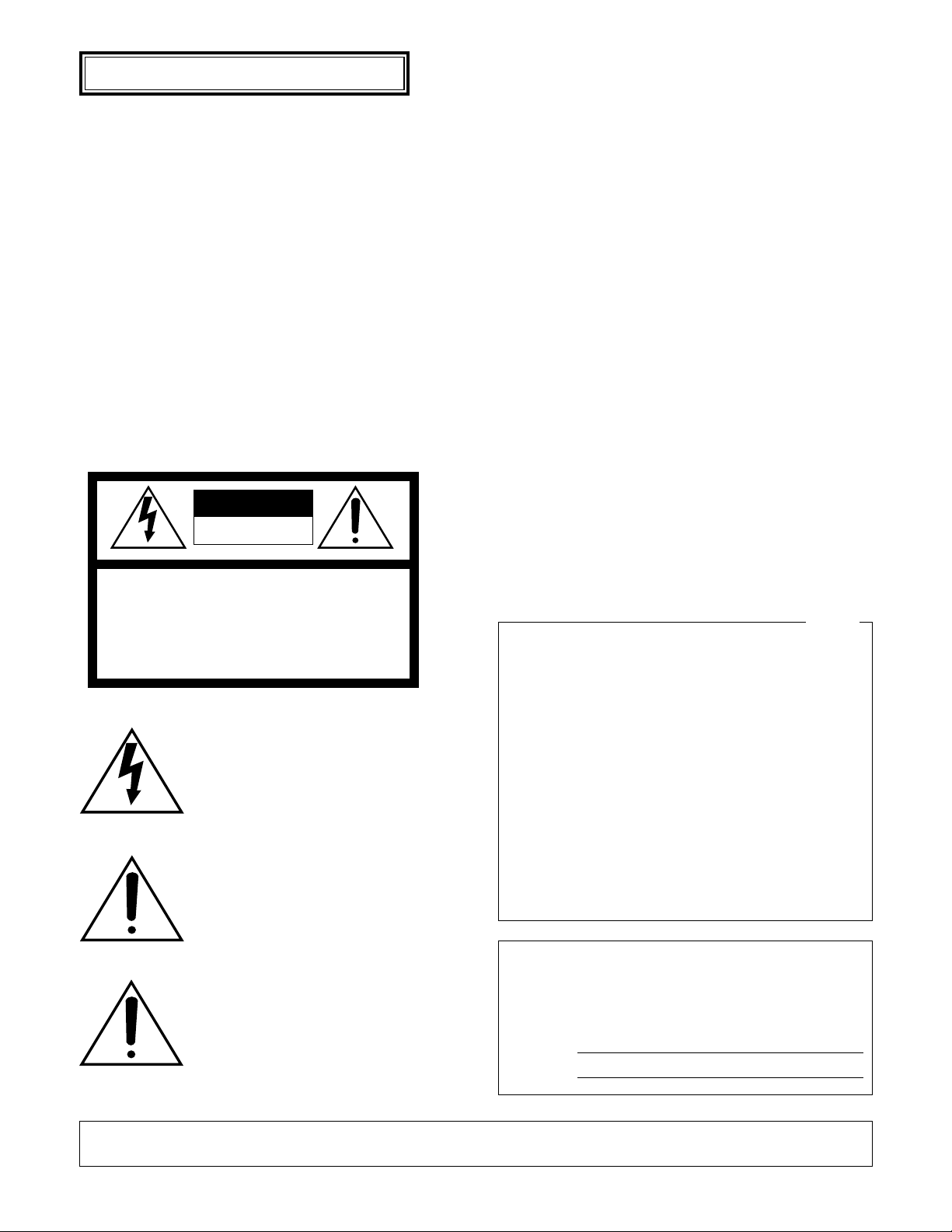
■ Crosspoint Switches
All matrix switchers, no matter how complicated and sophisticated they may be, depend on crosspoint switches to perform the
basic operations of the switcher. The crosspoint switches from a rectangular array of rows and columns in which any row may
be connected to any column.
In the figure shown above, the rows are connected to video cameras and the columns are connected to video monitors.
By closing a certain crosspoint switch we may connect any camera to any monitor.
In the example above, by closing switch SW12 the camera 2 is displayed on the monitor 1. Likewise, by closing SW24 camera
4 is displayed on the monitor 2.
■ Monitoring Mode
In the normal connection, this system can control up to 16 cameras, 4 monitors, and 4 system controllers. In the master-slave
connection, the system can control up to 64 cameras.
There are two surveillance ways:
One is the spot mode that associates one camera with one monitor. The other is the sequence mode that sequentially displays
the images through more than one camera.
● Spot Mode
The specified camera images are continuously displayed on a given monitor.
When another camera input is accepted, the images are replaced by new ones.
SW11 SW21 SW31 SW41
SW12 SW22 SW32 SW42
SW13 SW23 SW33 SW43
SW14 SW24 SW34 SW44
Page 11
11
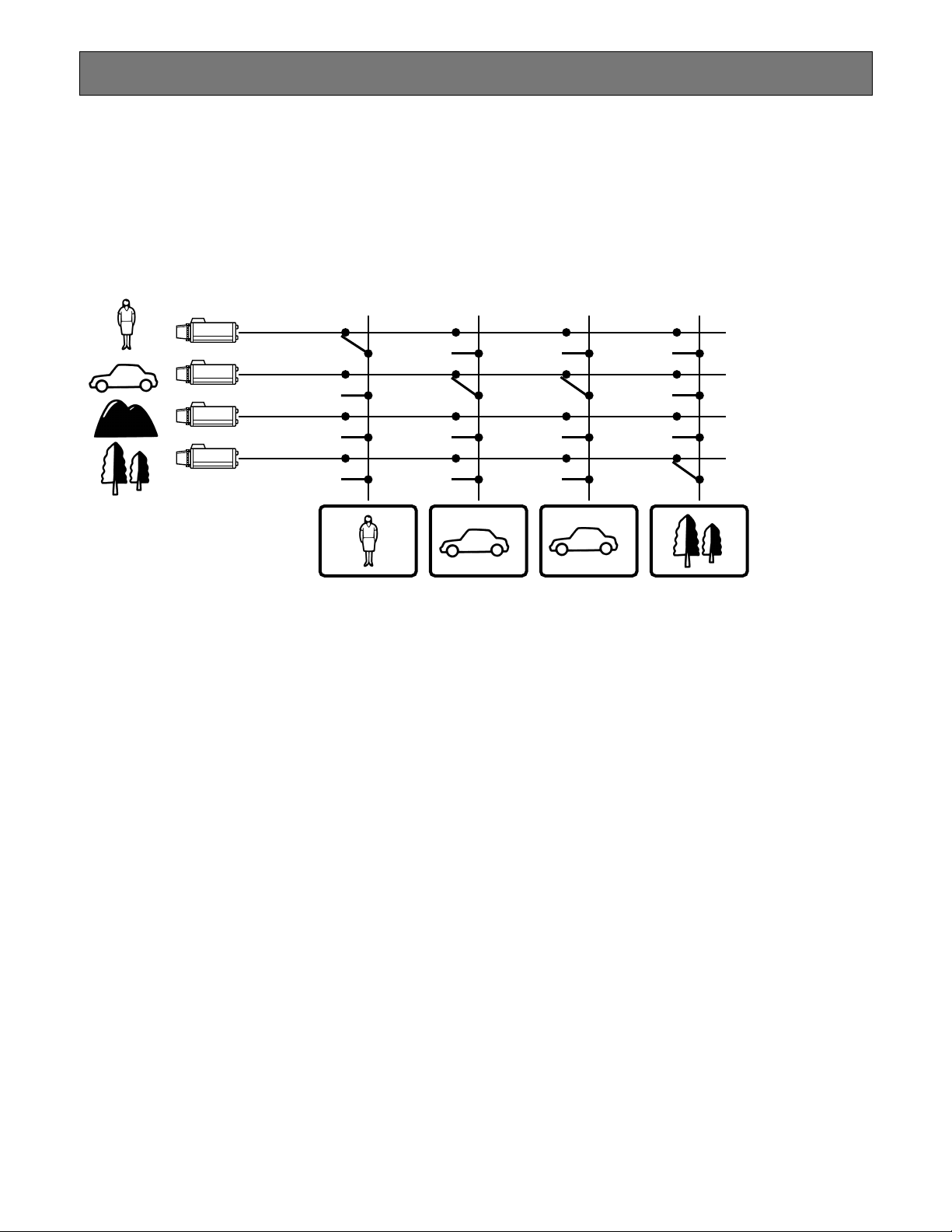
● Sequence Mode
More than one camera's images are sequentially displayed for a
fixed time.
The illustration shows an example of the sequential display of
images through Camera 2, 4, and 6 on Monitor 1.
Before use, the parameters* of the sequence need to be configured and uploaded to the unit.
* Example: Camera selection, monitor selection, and dwell time
(the time to display each image).
■ System Control
System controllers are used to control the equipment connected to this system.
● About System Controller
This matrix switcher system has four data ports: DATA 1 to 4. The ports DATA 1 to 3 supports the terminal mode, and the
DATA 4 port supports both the terminal mode and Panasonic Security Data (PS·Data) Systems. These are the operation mode
of the matrix switcher. When using the DATA 4 port, you can employ either of them. Refer to p. 14 for details of the terminal
mode. Refer to p. 22 for notification about PS·Data System.
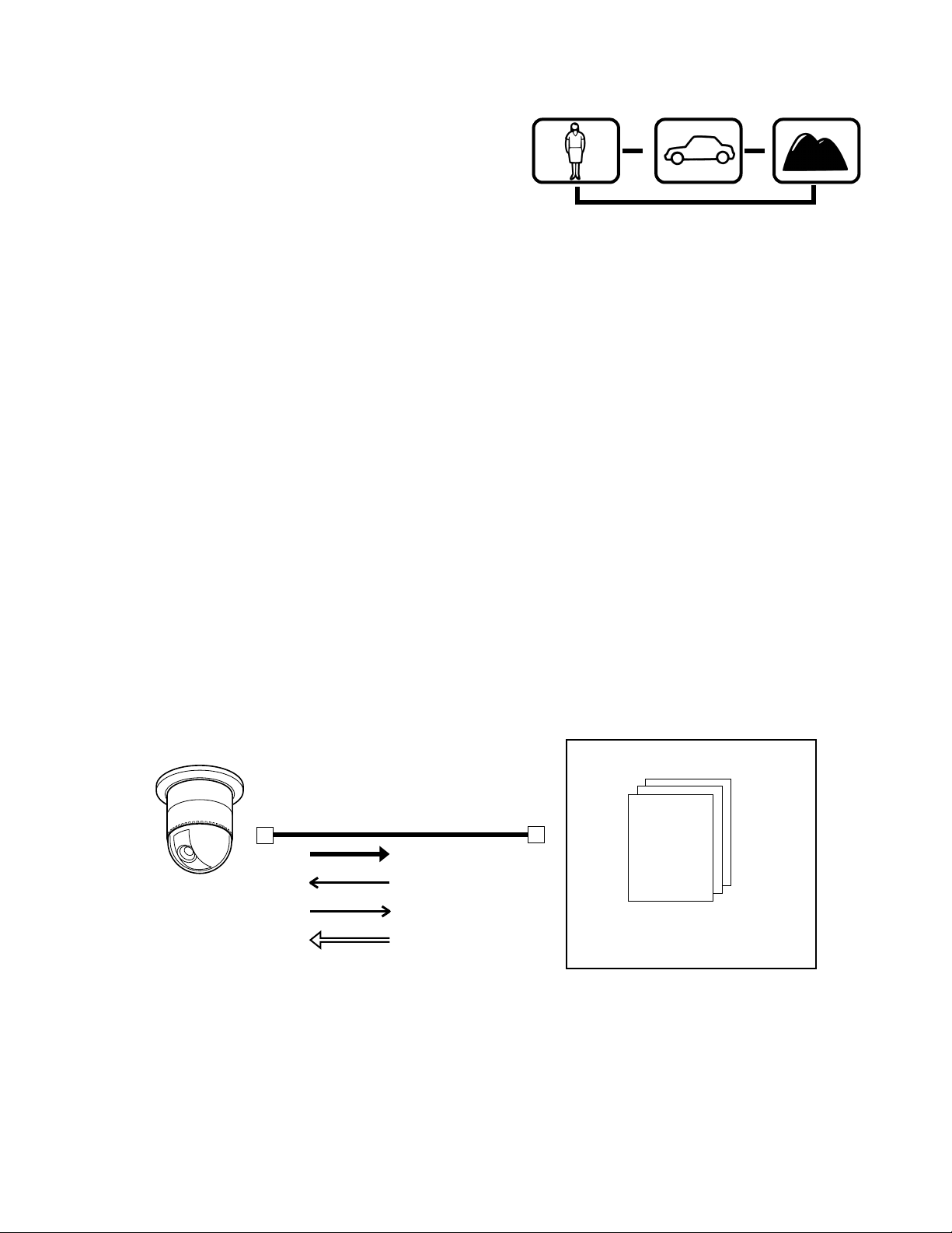
● Camera control
As the illustration, this unit sends the control data and VD2 timing pulse to the cameras.
On the contrary, the cameras send the video signal and state signal to the unit.
Control data is supplied via the coaxial cable from the unit, multiplexed with the camera image.
The unit is equipped with the circuit to multiplex or separate the video signal and control data with each channel.
These connections enable the control of the equipment from the system controller.
When using Panasonic RS-485 cameras, the unit can send the separated control data to them.
RS-485 cameras can be installed at longer distance from the matrix switcher than cameras that multiplex the control data.
Each signal functions as the illustrations in the next page.
VD2 provides the timing pulse of the same phase to prevent the unconformity during the switching of the image in a sequence
mode.
Multiplexed
data
Sync
signal
Every channel is equipped with
multiplexed data and sync
signal.
Matrix switcher
Coaxial cable
Video signal
Control signal
Status signal
Timing pulse (VD2)
Combination camera
Monitor 1
Dwell time: 2 sec.
Step 1
Monitor 1
Dwell time: 2 sec.
Step 2
Monitor 1
Dwell time: 2 sec.
Step 3
s
s
s
Camera 2
Camera 4 Camera 6
Page 12
12
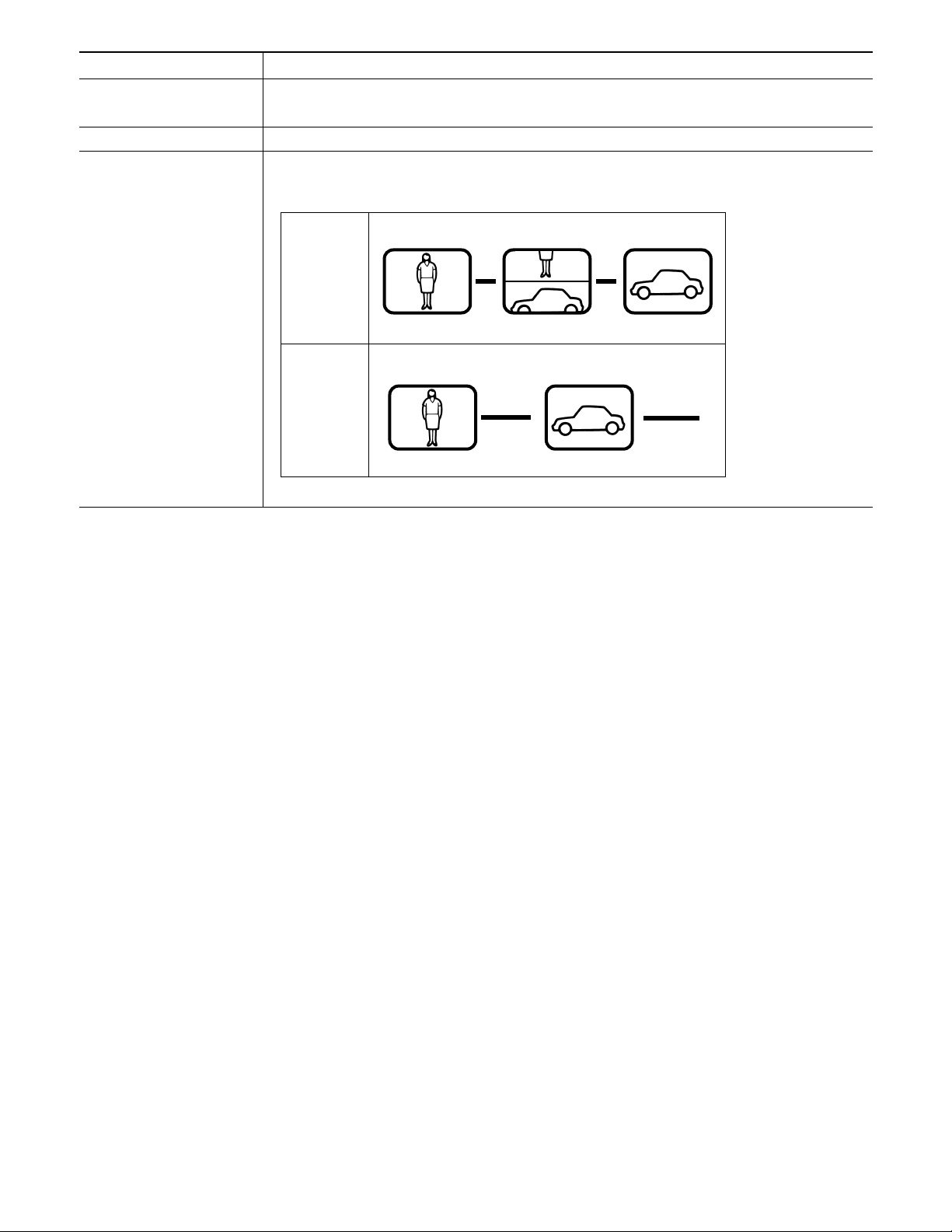
Signal type Function
Control signal Controls camera functions (pan/tilt, zooming, focusing, lens iris, preset position) and camera
site accessories.
Status signal Shows camera status.
Timing pulse (VD2) This signal is supplied to the unit to each camera.
Each figure shows the picture status with or without the timing pulse.
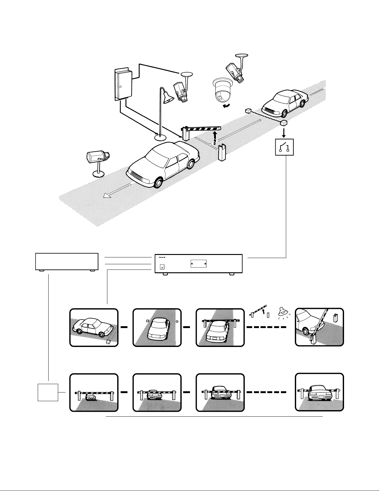
■ Example of a SYSTEM with Basic Functions
The illustration in the next page shows the surveillance system in a parking lot as an example.
Before the connections, the matrix switcher's system configuration* and the recorder's alarm recording setting are necessary.
Example: Operations of cameras and other connected equipment during an alarm input
1. The infrared sensor sends an alarm signal to the unit when detecting a car comes in.
2. The unit enters the sequence mode associated with Monitor 1.
At the same time, the unit controls the digital disk recorder to change its recording mode into the alarm-recording mode.
Monitor 1 is associated with the following sequence.
Displaying Camera 1's image
↓
Displaying Camera 4's image (Preset Position 1)
↓ Camera 4 moves from preset position 1 to 2 according to the sequence setting.
Displaying Camera 4's image (Preset Position 2)
↓
Controlling AUX 1 and 2 (The gate will open and the lamp will light up.)
↓
Displaying Camera 5's image
s
s
s
VD2 OFF
VD2 ON
s
Page 13
13
Monitor 2 displays Camera 6's image consistently in the spot mode.
Operators will observe the parking lot by looking at these images on a monitor in a management office.
Lamp
lights up.
(Aux 2)
Camera 1
Dwell time : 1 s
Camera 4/position 1
Dwell time : 3 s
Camera 4/position 2
Dwell time : 2 s
Gate
opens.
(Aux 1)
s
s
s
Camera 5
Dwell time : 30 s
s
s
s
Camera 1
Camera 4
Camera 5
Sensor
Aux 1
Aux 2
Receiver
Preset
position 2
Matrix switcher
Alarm 3
Alarm
Sequence mode
Alarm
mode
s
s
Monitor 1
Monitor 2
s
t
t
t
Camera 6
s
Alarm recording mode
Camera 6
Preset
position 1
Recorder
Page 14

14
TERMINAL MODE DESCRIPTIONS
In the terminal mode, each external device (such as a camera, monitor, system controller, or a recorder, etc.) has the
name and number (Camera 1, etc.). When you control a
device, you are to select the device number and execute the
selection. For example, before controlling Camera 1, you will
press the numeric button 1, and then press the CAM (SET)
button. Each operator has a level and priority. When you try
to control a device beyond the level and priority, the PROHIBITED or BUSY indicator will light up to inform you that you
cannot control it.
■ Log-in/Log-out
Before starting the system operation, it is necessary to input
an operator ID and a password from a system controller.
The system identifies the operator ID and password by comparing the registered data. If the ID and password are correct, the system will enter the operation mode.
This identification is called log-in. On the contrary, the termination of the system operation is called log-out.
Log-in/log-out has two ways: One is the manual log-in/log-out
and the other is auto log-in/out.
Through the auto log-in, an operator can login the system
without entering a password, after turning the power on.
Through the auto log-out, an operator can logout of the system when not operating the system for a fixed time.
The way of log-in/log-out and the time for auto log-out is configurable when setting up the system.
When configuring the auto log-in, it is necessary to assign an
operator ID to each data port.
● Operator Registration
When operating the system, the operator registration is necessary.
Up to 16 operators can be registered and filed by their operator IDs.
They are registered in SETUP MENU and WJ-SX150A
Administrator Console.
The following are the properties, which can prevent the operation conflict.
Level Setting
16 operators are classified in the level from 1 (the highest) to
3 (the lowest).
A higher-level operator can control more functions.
Password Setting
Up to 5 digit numbers can be registered as a password.
When an operator logs in, the system identifies the operator
ID and password by comparing the registered data.
If they are correct, the operator can control the system.
Priority Setting
The system classifies the operators in priority from 1 to 16.
This setting includes the control coverage that is configured
by level, and the priority in case of the conflict with the samelevel operator.
Operable Cameras and Sequences
This setting assigns each operator the cameras and
sequences operable by the level.
Notes:
• Each operator’s ID, password, level and priority need to
be configured in SETUP MENU and WJ-SX150A
Administrator Console.
• Auto log-in/log-out is configurable in WJ-SX150A
Administrator Console.
• The level and priority are assigned to each operator.
Operators cannot control the system beyond the assignment.
Even within the level and priority, a device controlled by
a higher-level operator is not operable.
• Manual log-in/log-out or auto log-in/log-out is assignable
to the system controllers Terminal – K1 to K4.
*n is a number.
• Description of Operator Registration
Operator 1
ID
Password
Level
Priority
Camera Operation
150
150
1
1
1
Operator 2
1
12345
1
2
1
Operator 3
100
100
1
3
1
Operator 4
101
101
1
4
1
Operator 5
102
102
2
5
1
Operator 6
103
103
3
6
1
• • •
Operator
n* (Max 16)
–
–
–
–
–
Level Table
SX150A Setup
Camera Setup
Program Preset Position
Camera Control
Camera Selection
Recorder Setup
Recorder Control
Camera Operation Level
1: This level can select and control the camera.
2: This level can only select the camera.
3: This level can neither select nor control the camera.
Items operable by
the level are set to
ON.
Page 15
15
SLAVE DOWN (Displayed when communication is not
established between the Master and Slave units: for
example, power/cable disconnection)
* “n” is a number.
Notes:
• When pressing the associated numeric button (1 to 5)
while holding down the OSD button, information is
turned on or off.
• When you select the LCN (logical camera number) not
assigned in the system, “NOT ASSIGN” will appear
beside the camera number.
● The Display Position
The display position of the information is adjustable with the
joystick on the system controller.
● Priority Lock
Priority lock is the function to prevent other operators' control of a monitor even after the system log-out.
While the priority lock is active, the monitor is operable by
the locking operator and higher-priority operators.
● Sequence Mode
Camera images are displayed for a fixed time, and they are
sequentially switched.
The change from a tour sequence into the spot mode is
also possible.
Before use, the parameters of the sequence, such as a
camera or monitor selection and dwell time need to be configured.
There are two sequences:
• Tour sequence
• Group sequence
Tour Sequence
The images through Camera 1 to 99 are displayed on a
given monitor in the desired sequence.
A tour sequence is consisted of 64 steps and up to 32
sequences are configurable.
Up to 30 seconds are selectable as each step's dwell time.
Each step can call the desired preset position of a camera
to be displayed.
■ Monitor-related Functions
The following functions related to monitors are configurable.
● Monitor Selection
It is necessary to select a monitor when controlling the
monitor-related functions, such as camera images or
SETUP MENU.
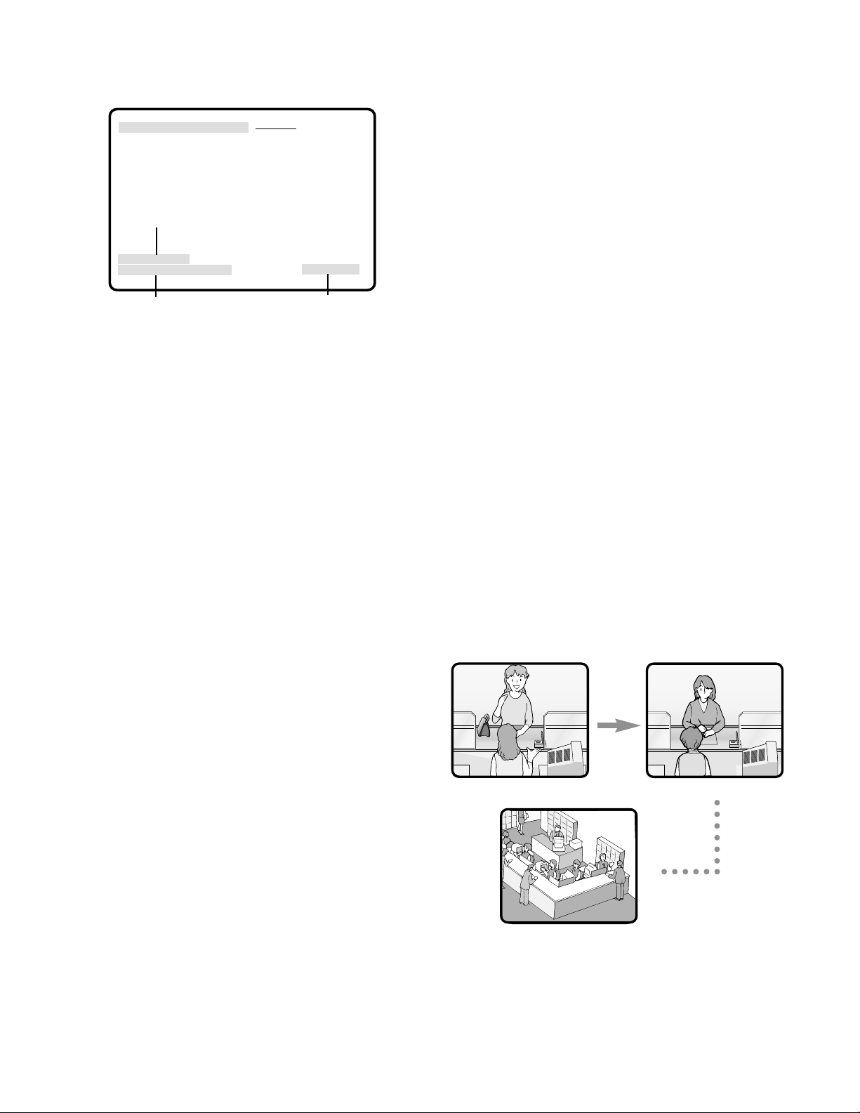
● Information Displayed on the
Monitors
The following information is displayed on monitors.
Time and Date
Time and date are displayed.
The date display is selectable from five patterns, and the
time display is selectable from 24- or 12- hour system.
The date display pattern (Example: August 21, 2001)
21/08/2001
08/21/2001
21/Aug/2001
2001/08/21
Aug/21/2001
Camera Title
The camera number (C01 to C99) and characters (up to 20)
can be configured as a camera title.
The title is displayed in one line.
Monitor Status
The following status is displayed in one line.
Mn (Monitor number)*
Kn (Controller number)*
Tnn (Monitor mode: the example shows the tour
sequence)*
Rn (Recorder number)*
* "n" is a number.
Event
The information related to system operation is displayed.
An alarm control, alarm suspension, and timer event are the
example.
ALARMnn (The alarm is operating.)
ALARMnn ACK (The alarm has been acknowledged.)
Tnn (Timer event: tour sequence number)
LOSS CHnn (the video loss channel number)
ALM SUSPENDED (The alarm is suspended.)
CAM SW LOSS Rn* (Displayed when no camera switching pulse is supplied from Rn)
Clock
Monitor status
Camera title
Event
CH1 CH2
CH3
08/21/2001 6:50:08 PM
M1 K1 T01
C01 camera title ALARM10*
Page 16
16
In each step, the desired preset position of a camera can
be called and displayed.
Tour sequences are configurable in SETUP MENU and WJSX150A Administrator Console.
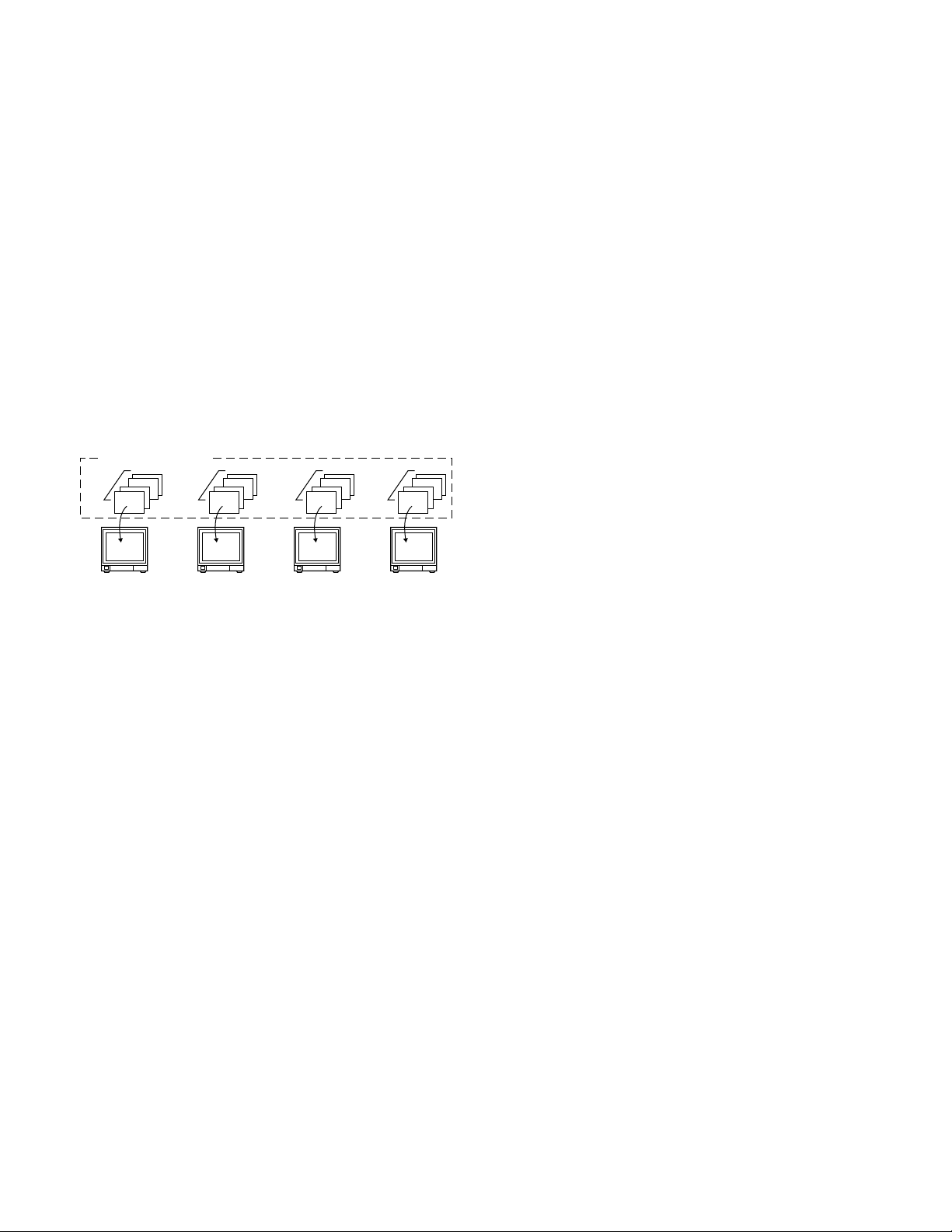
Group Sequence
Group sequence is a function to display up to 4 tour
sequences in a group on up to 4 monitors. More than one
sequences can be activated at one time by registering
each tour sequence in a group.
Up to 4 tour sequences can be registered in a group.
Notes:
• Up to 4 group sequences are configurable in WJSX150A Administrator Console. The configuration in the
matrix switcher's SETUP MENU is unavailable.
• The black picture is displayed when the following are
included in a tour or group sequence: a camera channel without image or the image restricted to the operator.
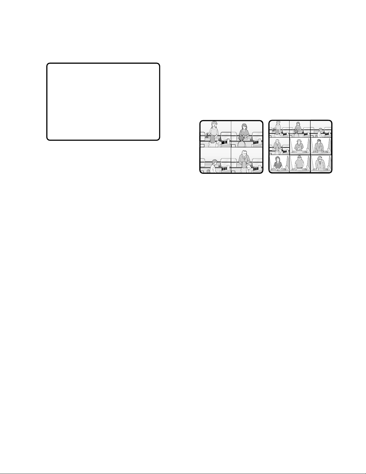
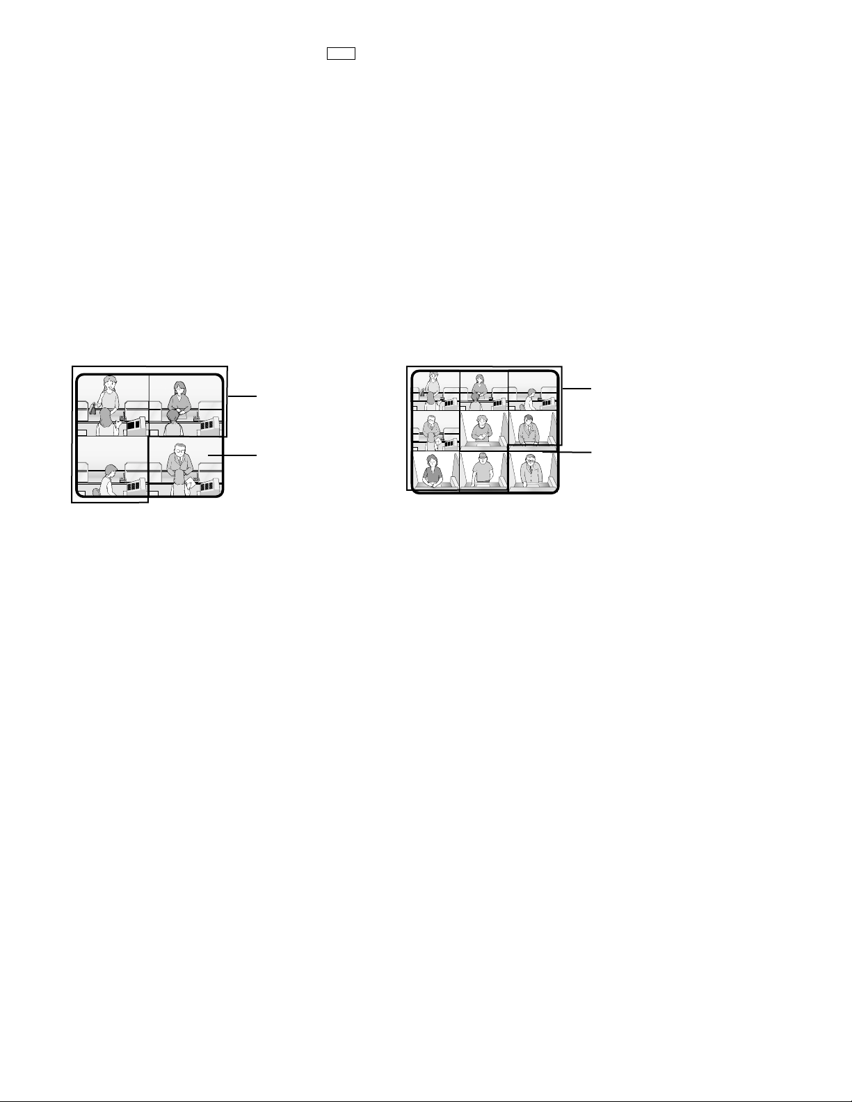
● Multiscreen Display (4, 9, and 16 Screens)
With a recorder, more than one camera images can be displayed in 4, 9, and 16 multiscreen segments.
Refer to p. 129 EXPANDED FUNCTION for details.
■ Camera-related Functions
This system can operate the following camera-related functions.
Notes:
• When operating the motorized zoom lens, a combination camera is necessary.
• A motorized zoom lens needs to be installed on a camera. Confirm the system components.
● Camera Selection
The camera needs to be selected when controlling the
camera-related functions such as a lens zoom, pan/tilt
head, or spot image of a camera.
● Operating Zoom Lens
Note: Make sure that the lens selection switch (DC/VIDEO)
is set to DC.
Focus
This setting adjusts the lens focus.
An auto-focus camera can automatically adjust the focus.
Zoom
This setting adjusts the lens zoom rate.
Iris
This setting adjusts the lens iris .
● Pan/Tilt Head Control
Pan/Tilt
Camera rotates on the pan/tilt heads.
There are two ways of control:
• Manual control by the joystick
The joystick on the system controller can control a camera's pan/tilt head.
• Preset position control
Entering preset position number can automatically
rotate the camera to the desired position.
It is necessary to register a camera's preset position
numbers.
The specified cameras support the registration during
the pan/tilt head control.
Notes:
• Depending on the system components, the specified
combination cameras are not operable.
• The speed varies depending on cameras.
• Some cameras' pan/tilt speeds cannot be controlled by
the joystick.
(Refer to the camera's operating instructions for
details.)
Auto Pan
The camera automatically turns within the preset panning
range.
Sequence Mode
The camera turns in the sequence of preset positions in
numerical order.
Sort Mode
The camera turns in the sequence of preset positions
counterclockwise from pan/tilt starting point.
Patrol Learn
The combination camera can learn and reproduce a routine
of manual operation.
There are two ways of patrol learn:
• Learning during the operation
• Configuration in the camera's SETUP MENU
● Housing Control
The wiper or defroster of the camera housing can be controlled.
Group sequence 1
Tour 1 Tour 5 Tour 2 Tour 7
Monitor 1 Monitor 2 Monitor 3 Monitor 4
Page 17

Notes:
• The images cannot be displayed while cleaning the
camera. Use this function when continuous surveillance
is not necessary, such as after-hours time.
• Cameras which are operating or being in the sequence
mode are not cleaned.
• Camera selection will immediately stop the camera
cleaning.
• If noise remains in the monitor even after the camera
cleaning, there can be a malfunction. Stop using the
camera and consult qualified service personnel.
■ Alarm-related Functions
This unit is equipped with 16 alarm input connectors. When
an alarm input signal is accepted via one of them, the
alarm-associated spot image or tour sequence image is
displayed on the monitor. With the alarm image on the monitor, the unit notifies you of the alarm information with
"ALARM nn (nn is the alarm number)."
There are two ways to display the alarm-associated image:
• Sequence mode
• Hold mode
Notes:
• The camera (or tour sequence) and monitor need to be
associated with the alarm number through the configuration in SETUP MENU (OSD) or WJ-SX150A
Administrator Console.
• The mode is selectable and configurable in SETUP
MENU (OSD) or WJ-SX150A Administrator Console.
• Even in the alarm mode, pressing the ACK button can
control the camera's pan/tilt, zoom, focus and lens iris.
• When a recorder is connected to the matrix switcher,
the alarm-related recording of the camera images is
possible.
17
● External Equipment Control
When the camera is connected via a receiver, the external
equipment connected to the receiver can be controlled.
● Controllable Camera-related
Functions
The control is conducted while watching the camera
images on the monitor.
• Changing to black and white pictures
• Camera function (Shortcut function)
Note: The specified cameras can control each function.
Confirm the functions of the connected cameras and
external devices.
Changing to Black and White Pictures
Color images are changeable to black and white images.
This function is intended for surveillance in a dark place
such as an underground parking lot.
Camera Function (Shortcut Function)
The frequently-used functions are registered with the camera function button.
Pressing the button can activate the registered functions.
Refer to the camera's operating instructions for details on
the registered functions.
● Camera Title
The titles for camera identification, which are displayed on
the monitor, can be registered.
For example, if a camera setting place is registered as a
camera title, operators can be informed where the image is
recorded.
The title is displayed in one line.
The available character numbers:
20 (camera number and the characters)
The available characters:
ABCDEFGHIJKLMNOPQRSTUVWXYZabcdefghijkl
mnopqrstuvwxyz0123456789!"#$%&'()=+*_:;,. */?
Notes:
• Camera title is configurable in SETUP MENU and WJSX150A Administrator Console.
• User font characters can be made through WJ-SX150A
Administrator Console.
● Camera Cleaning
When using a combination camera, noise can occur on the
monitor after the long-term use.
In this case, the camera needs to be cleaned.
Camera cleaning is configurable to be conducted at the
designated day and time.
The cleaning time is approximately 30 seconds per camera.
• Description about sequence mode and hold mode
Sequence
mode
Alarm
input 1
Camera image
Alarm
input 1
Alarm
input 5
ALARM 01 ALARM 05
Dwell time
Alarm
input 5
Alarm
input 2
Automatically replaces
the alarm image
Alarm
input 2
ALARM 02
Hold mode
Camera image
ALARM 01 ALARM 05
Alarm reset operations
Time
Page 18

18
● Sequence Mode
In the sequence mode, the unit displays the initial alarm
image on the monitor until the dwell time ends, even when
another alarm input is accepted. When the dwell time ends,
the unit automatically replaces the alarm image with the
next one.
● Hold Mode
In the hold mode, the unit continues to display the initial
alarm image until the alarm reset. With the alarm image on
the monitor, the unit notifies you that more than one alarm
input is accepted with "*" next to "ALARM nn (nn is the
alarm number)."
● Alarm Reset
The built-in timer automatically resets the alarm operation
after the time specified in WJ-SX150A Administrator
Console.
After the reset, the monitor displays and the sequence will
return to the state before the alarm input.
Note: When more than one alarm input has been accepted,
only the newest can be reset.
● Alarm Suspension
Even when an alarm signal is input, the system will deactivate the alarm input and the alarm mode.
When the alarm suspension is active, "ALM SUSPENDED"
will appear on the monitor.
● Alarm History Table
This table displays the alarms that have occurred in the
past.
The alarm order, date, time, alarm number and event can
be identified.
Up to 100 item can be reserved, and they are overwritten
from the oldest, after more than 100 item have occurred.
Notes:
• When turning off the unit, all the history will be deleted.
• Alarm history can also be identified on the PC.
● Video Loss History Table
While the unit's power is ON, the video signal loss from a
camera or a recorder can occur by cable disconnection,
etc.
In this case, video loss history will be reserved in the system, and this table will display the history.
The loss order, date, time, camera number/recorder number and event can be identified.
Up to 100 item can be reserved, and they are overwritten
from the oldest, after more than 100 item have occurred.
As well as the video loss history, the date of the loss and
recovery, the camera number and the loss status are displayed on the table.
Notes:
• When turning off the unit, all the history will be deleted.
• Alarm history can also be identified on the PC.
■ Timer Event
The built-in timer can automatically start the sequence or
spot mode on the specified days, which is configurable in
WJ-SX150A Administrator Console.
The available operations:
Tour sequence and spot mode
The available timer events:
Up to 50
Note: When displaying SETUP MENU while timer event is
operating, the operation will stop.
VIDEO LOSS HISTORY 1 of 2
NO YYYY/MM/DD HH:MM:SS CH EVENT
012 2002/08/21 18:59:08 99 VIDEO RECOVER
011 2002/08/21 18:58:08 14 VIDEO RECOVER
010 2002/08/21 18:57:08 99 VIDEO LOSS
009 2002/08/21 18:55:08 07 VIDEO LOSS
008 2002/08/21 18:54:08 R0 SW RECOVER
007 2002/08/21 18:53:08 16 VIDEO LOSS
006 2002/08/21 18:53:00 09 VIDEO LOSS
005 2002/08/21 18:52:08 R0 SW LOSS
004 2002/08/21 18:51:08 S1 SLAVE DOWN
003 2002/08/21 18:50:08 S1 SLAVE RECOVER
ALARM HISTORY 1 of 2
NO YYYY/MM/DD HH:MM:SS ALARM EVENT
016 2002/08/21 18:59:08 80 ALARM
015 2002/08/21 18:58:08 80 ACK
014 2002/08/21 18:57:08 80 RESET
013 2002/08/21 18:55:08 07 ALARM
012 2002/08/21 18:54:08 07 ACK
011 2002/08/21 18:53:08 07 RESET
010 2002/08/21 18:53:00 09 ALARM
009 2002/08/21 18:52:08 09 RESET
008 2002/08/21 18:51:08 06 ALARM
007 2002/08/21 18:50:08 06 ACK
Page 19
19
■ Extended Functions
If a recorder is connected to the matrix switcher, the following will be available.
● Recorder Connection
The operations are conducted with the buttons on the
recorder, system controller or PC.
• The setup of the recording device
• The playback of the recorded images (the multiscreen
display, still picture, etc.)
• The search for the recorded image
• Forward or backward search
• Forward of backward field advance
• Fast-forward
• Rewind
• Index
Refer to each device's operating instructions for details.
■ System Status Table
The current system status can be identified.
The continuous display becomes possible by the OSD setting.
MON: Monitor number
CAM: Camera number / Recorder number
MODE: Operation mode
KB: Controller name
OPE: Operator number
PRI: Priority
■ Setup Procedures
To use the unit, it is necessary to configure the system
through the following setup procedures:
• OSD setup with an active monitor and system controller
The basic parameters are configurable to operate the
unit.
• WJ-SX150A Administrator Console with the PC
The setup utility can configure all the functions of the
unit.
Refer to p. 63 WJ-SX150A SETUP MENU (OSD) and p. 79
WJ-SX150A ADMINISTRATOR CONSOLE for details.
SYSTEM STATUS
MON CAM MODE KB OPE PRI
1 01 T01 K1 12345 30
2 99 SPOT K2 2 2
3 04 ALARM K4 4 1
4 R1 RECORDER PC 30 1
Page 20
20
● Multiplexer Board Function
To use WJ-HD 100 Series or a time-lapse VCR as a recorder, you need to install a Multiplexer board inside the matrix switcher.
With the Multiplexer board installation, the following will be available.
• Multiscreen display
More than one camera images can be displayed in 4, 9, and 16 multiscreens.
The sequence output is also available.
As the sequence output, the following are configurable in WJ-SX150A Administrator Console.
• The images are switched within 4 multiscreens. (QUAD)
• The images are displayed in 4 multiscreens, and the images of Camera 4 to 16 are displayed in the sequence mode.
The images of Camera 1 to 3 are fixed.
(3+1→2S)
• The images are displayed in 9 multiscreens, and the images of Camera 9 to 16 are displayed in the sequence mode.
The images of Camera 1 to 8 are fixed.
(8+1→2S)
Notes:
• The black image will be displayed for a camera channel which is not connected to the camera.
• Even during the multiscreen display, pressing the camera number can display the camera's image in the spot mode.
• Still display
The desired image can be displayed in a still picture.
Live images can be displayed in multiscreen display.
Playback images can be displayed in spot/multiscreen display.
"STILL" will appear on the active monitor.
• Zoom
The desired image on the monitor can be zoomed up to two fold.
Note: This function is available only when a playback image is displayed in a spot picture.
• Alarm priority mode
When an alarm is activated and the alarm signal is input to the unit, the camera channel with the alarm input will be recordable
according to the configuration in SETUP MENU and WJ-SX150A Administrator Console.
The following are configurable as the recording mode when the alarm is activated:
• The camera channel with the alarm input is given recording priority. (ALM-PRI)
• Only the camera channel with the alarm input is recorded. (ALM-ONLY)
• Up to 4 camera channels are assigned to an alarm input to record the images by priority. (GROUP)
Notes:
• The recording mode needs to be configured in SETUP MENU and WJ-SX150A Administrator Console in advance.
• Detailed settings of GROUP is configurable only in WJ-SX150A Administrator Console.
CH9 to CH16 are in a
sequence mode.
CH1 to CH8 are fixed.
CH4 to CH16 are in a
sequence mode.
CH1 to CH3 are fixed.
MUX
Page 21

21
• Motion detector
When the multiplexer board detects motions in the image, the Multiplexer board sends an alarm signal to the unit.
Then, the unit will send the alarm signal to the connected devices.
The areas can be divided in four segments, and the detection is conducted in each segment.
For example, this function can be applied to a time-lapse recording, which responds to the break-in at night.
Notes:
• The motion-detection area needs to be configured in SETUP MENU in advance.
• The range of the motion detector is also configurable in the WJ-SX150A Administrator Console.
• When connected with Digital Disk Recorder WJ-HD100 Series/time-lapse VCR
The multiplexed recording and playback of all the camera images connected to the unit are possible.
Each camera's image and camera ID are recorded.
The camera ID can search and play back the desired camera's image.
The digital disk recorder (WJ-HD100 Series) connected to the unit and time-lapse VCR have the following functions.
The operations are conducted with their buttons or the system controller or the PC.
• The setup of the recording device (HD100 only)
• The start of the playback
• The stop of the playback
• The playback of the recorded images (the multiscreen display, still picture, zoom spot picture)
• The search of the recorded image (the search by the recorded time and date) (HD100 only)
• Forward or backward search
• Forward or backward field advance
• Fast-forward
• Rewind
• Index (HD100 only)
Refer to each device's operating instructions for details.
Notes:
• When recording on the WJ-HD100 Series or time-lapse VCR, an optional Multiplexer board needs to be installed in this
unit.
• Only Panasonic time-lapse VCRs supporting RS232C are operable.
● Master-slave Connection
When applying this connection, up to 5 matrix switchers (units) and 64 cameras can be connected in a surveillance control
system. One of the units is designated as Master and others as Slave 1 to 4. Each unit has camera channels (CAM 1 to 16).
Cameras have logical camera numbers (LCN 1 to 99), which are uniquely assigned for camera control and monitor display.
(Refer to pp. 49 to 52 for illustrations.)
Page 22

22
In the factory default setting, you can control the unit, if you connect a PS·Data system controller to the DATA 4 port. For example, if you connect a PS·Data unit supporting network connections (refer to p. 42), remote-control of the unit and the PS·Data
units will be available with a system controller or PC.
When you use a PS·Data system controller, take notice the following:
• The administer authorization and log-in/log-out procedure differs from the unit. They are conformed to the system controller. Refer to the system controller's operating instructions.
• Use the PS·Data template supplied with the system controller, as the operating procedures differ from those of the terminal
mode. (Refer to pp. 123 to 128.)
• When connecting a recorder to the unit, you may have to configure the settings of the unit and recorder, depending on the
recorder's available functions and connections. (Refer to pp. 40 to 55.)
NOTIFICATION ABOUT PS·DATA CONTROLLER OPERATION
Page 23

23
DETAILED PRODUCT
DESCRIPTION
Page 24
24
MAJOR OPERATING CONTROLS AND THEIR FUNCTIONS
■ WJ-SX150A Matrix Switcher
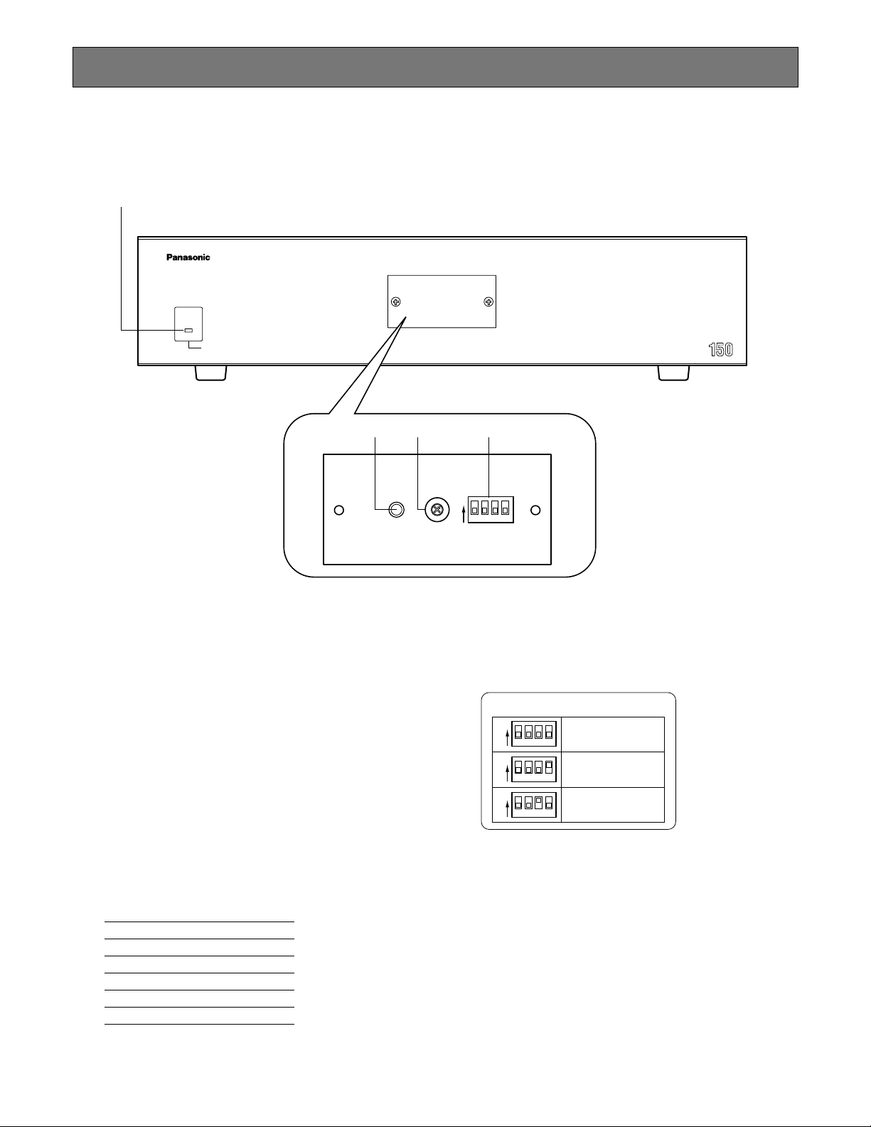
● Front View
q Operation indicator (OPERATE)
Lights up when the power of the unit is turned on.
Note: The indicator will blink to indicate rising tempera-
ture in the matrix switcher.
When the indicator blinks, turn the power off and
refer servicing to qualified service personnel.
w Reset button (RESET)
Resets and restarts the unit.
Note: The system configuration is not reset.
e Unit number selector (UNIT)
Normally, set this selector to “0”.
When applying the master-slave connection, set this
selector to one of the following unit numbers. (Refer to
pp. 49 to 55 for details on the master-slave connection.)
Master/Slave Unit number
Master 0
Slave 1 1
Slave 2 2
Slave 3 3
Slave 4 4
r Mode selector (MODE)
Selects the unit's operation mode.
Normally, set all switches to OFF (NORMAL mode) as
shown in the figure.
SX150A SOFTWARE UPLOAD:
Set the switches to this position when you update
the firmware of the unit. (Refer to the operating
instructions of the Multiplexer board.)
MULTIPLEXER SOFTWARE UPLOAD:
This mode is reserved for future use.
Matrix Switcher WJ-SX A
OPERATE
OPERATE LED WILL BLINK
IF COOLING FAN MALFUNCTIONS
q
0
9
8
7
6
5
4
3
2
1
MODEUNITRESET
we r
1ON234
MODE SW SETUP
1ON234
1ON234
1ON234
NORMAL
SX150
SOFTWARE UPLOAD
MULTIPLEXER
SOFTWARE UPLOAD
Page 25
25
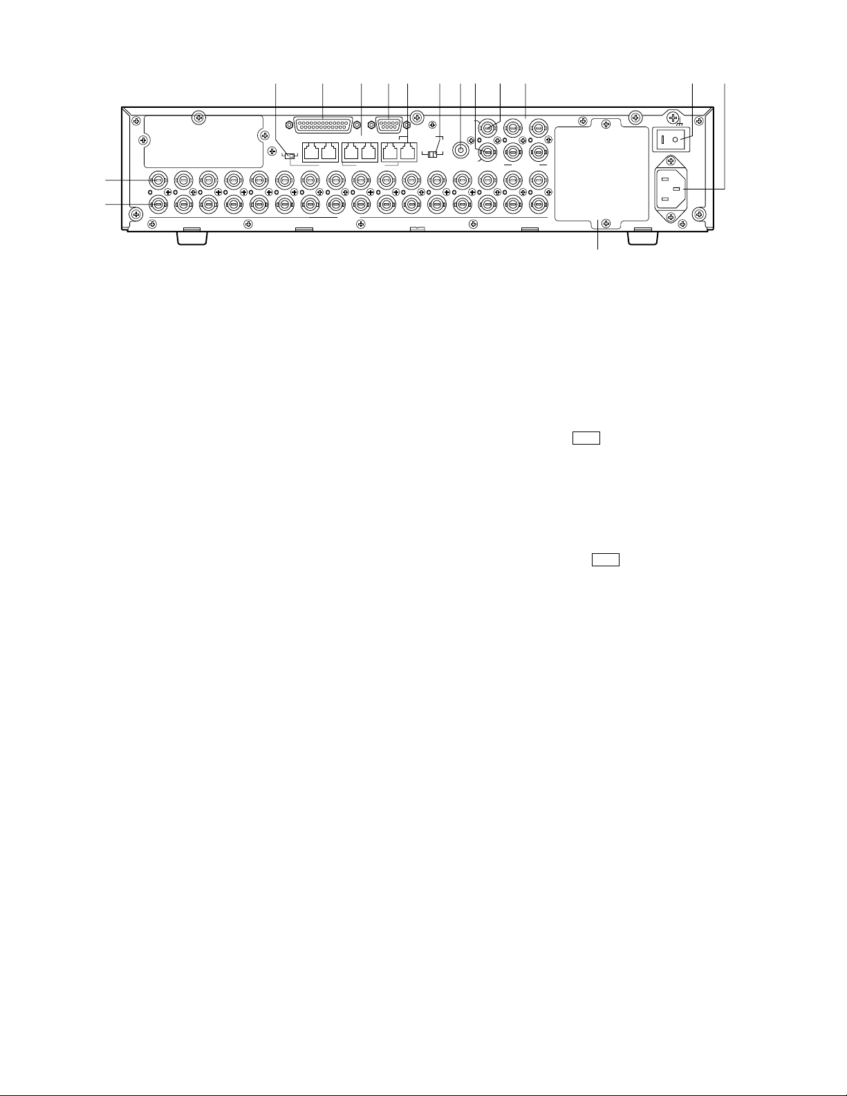
● Rear View
t Camera Output connectors (CAMERA OUT 1–16)
The video signal connected to the CAMERA IN connector is supplied at these connectors.
When the power of the matrix switcher is turned off, no
signal is supplied at these connectors.
y Camera Input connectors (CAMERA IN 1-16)
• Connect to cameras or camera site accessories.
These connectors accept either a composite color or
B/W video signal from a camera.
In addition, the VD2 signal to synchronize the vertical
timing of the cameras, and data to control camera site
devices are multiplexed at these connectors.
• When applying the master-slave connection, the functions of connectors will differ. (Refer to p. 53 for details.)
u Termination selector (TERM ON/OFF)
When you connect a PS·Data system controller to the
DATA 4 port, this selector turns the unit's termination
switch to ON/OFF.
The factory default setting is ON.
Note: When you connect a terminal-mode system con-
troller to the DATA 4 port, set this selector to ON.
i Alarm port (ALARM)
Connects to alarm sensors.
Accepts the alarm input from the associated alarm sensors.
o Data ports (DATA 1/2/3/4/DATA HDR)
• DATA 1 to 4 connect to the system controller.
DATA 1 to 3 can connect to RS-485 cameras with the
configuration in WJ-SX150A Administrator Console.
(Refer to p. 96.) DATA 4 can connect to the system
controller via the PS·Data protocol.
• DATA HDR connects to a recorder.
• When applying the master-slave connection, the func-
tions of ports will differ. (Refer to p. 53 for details.)
!0 Serial port (SERIAL)
Connects to a PC for the system configuration through
WJ-SX150A Administrator Console.
!1 RS-485 Camera port
• Connects to an RS-485 camera.
Daisy chain connection is also available.
• When the unit is used as Master in the master-slave
connection, terminal-mode system controllers can be
connected.
Note: To connect terminal-mode controllers, the setting
in SETUP MENU and WJ-SX150A Administrator
Console is required. (Refer to pp. 61 to 102 for
details.)
!2 Line selector (LINE SELECT 2/4)
Lets you select either full duplex (4 lines) or half duplex
(2 lines) for RS-485 cameras.
!3 Camera Switching Input connector
(CAMERA SW IN)
The camera switching pulse from the time lapse VCR is
supplied to this connector.
The camera switching interval (Sequential Dwell Time)
can be synchronized with the time lapse mode set in
the associated time lapse VCR.
!4 External Output connector
(EXT OUT/REC OUT)
The recording signal for the recorder is provided via
this connector.
!5 External Input connector (EXT IN/PLAY IN)
A playback or live images from the recorder are supplied to this connector.
!6 Monitor Output connectors (MONITOR OUT 1/2/3/4)
• Connect to monitors.
The video output signals are supplied to the monitors at
these connectors.
• When applying the master-slave connection, the functions of connectors will differ. (Refer to p. 53 for details.)
!7 Power switch (POWER)
Turns the power of the matrix switcher on and off.
!8 AC Inlet socket (AC IN)
To use the unit, plug the power cord (supplied as a
standard accessory) into this socket and connect it to
an AC outlet.
!9 Blank panel
When the Multiplexer board installed in the unit, remove
this panel and then attach the cooling fan inside the
unit. (Refer to the Multiplexer board’s operating instructions.)
Note: Fan unit needs replacement after around 30 000
hours of operation.
uio!0
!1 !2 !3 !4 !5 !6
!7 !8
SERIALALARM
DATA 3 DATA 2
DATA 4DATA HDR
TERM
OFF ON
PS•DATA
RS485(CAMERA)
8
9
10
11
12
13
14
15
16
y
t
IN
OUT
16
14
15
12
13
10
11
9
CAMERA
8
DATA 1
7
7
RS485(CAMERA)
LINE
SELECT
2
6
6
EXT IN
(PLAY IN)
CAMERA
SW IN
4
EXT OUT
(REC OUT)
3
4
5
3
4
5
3
4
MONITOR OUT
2
2
1
2
1
1
MUX
SIGNAL GND
POWER
AC IN
!9
MUX
Page 26
26
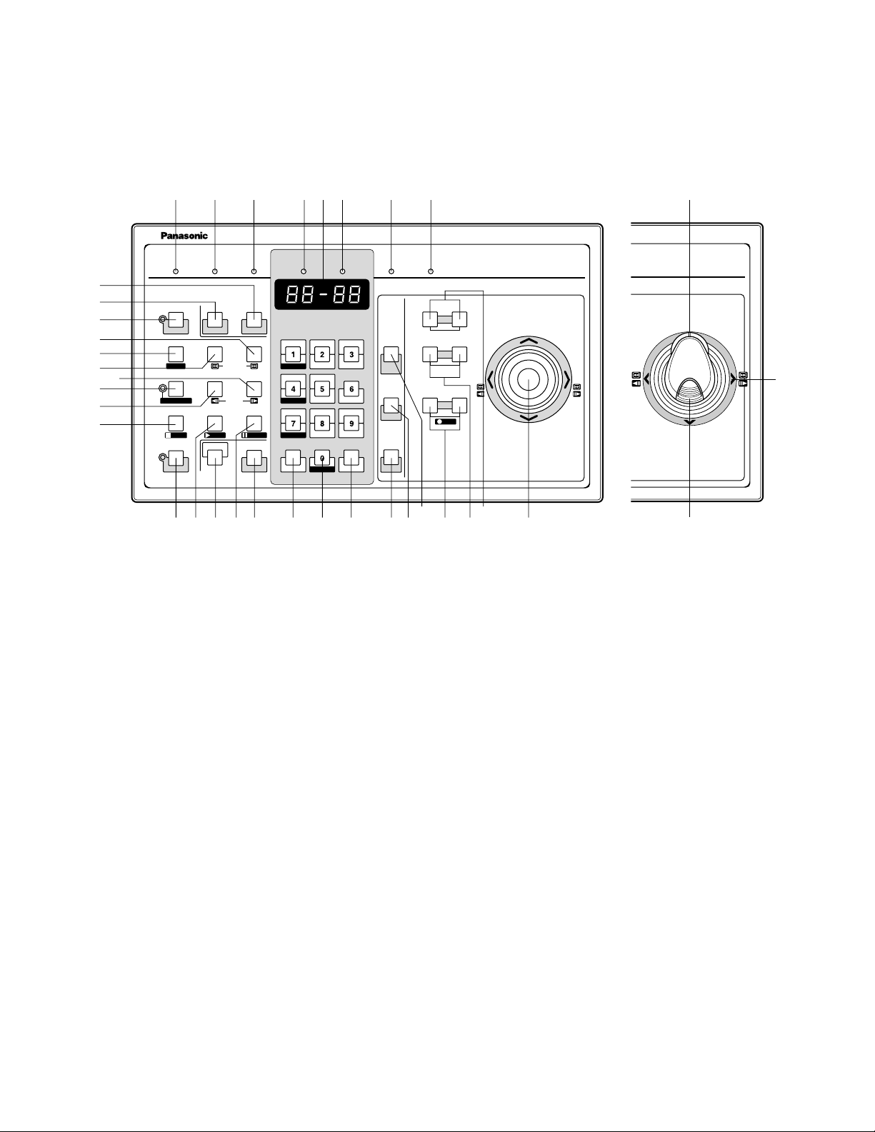
@0 Operation indicator (OPERATE)
Lights up when the controller's power is turned on.
@1 Link indicator (LINK)
Lights up when communication is established with the
matrix switcher.
@2 Alarm indicator (ALARM)
Lights up when an alarm condition exists.
@3 Monitor indicator (MONITOR)
Lights up when the monitor number appears on the
LED display.
@4 LED Display
Displays the monitor number, camera number, numeric
entry and error status, etc.
@5 Camera indicator (CAMERA)
Lights up when the camera number appears on the
LED display.
@6 Busy indicator (BUSY)
Lights up when the higher-priority operator selects the
camera or monitor you are currently operating.
Operations from the system controller are disabled until
this indicator goes off.
@7 Prohibited indicator (PROHIBITED)
Blinks when an operator attempts to control a monitor
(or camera) that is already used by a higher-priority
operator or the operator has done the prohibited operation.
@8 Joystick
Use this joystick to manually operate cameras, camera
site accessories and a recorder, or to move the cursor
in SETUP MENU on the active monitor screen.
UP: Up
DOWN: Down
L: Left, rewind*, backward field advance*
R: Right, fast-forward*, forward field advance*
*Available after pressing the RECORDER button while
connecting to a recorder.
@9 Iris buttons (IRIS CLOSE/OPEN)
Close or open the lens iris of cameras equipped with
the specified lens.
Press the CLOSE and OPEN buttons simultaneously.
The lens iris is reset to the factory default setting.
■ WV-CU360C/CU360CJ System Controller (TERMINAL MODE)
A template, on which “For Matrix Switcher (WJ-SX150A)” is written, is provided with a system controller. When using the template, place it on the surface of the controller.
In these operating instructions, this template's illustrations are used for descriptions.
● Front View (WV-CU360C) ● Front View (WV-CU360CJ)
360
360
@0 @1 @2 @3 @5@4 @6 @7
OPERATE LINK ALARM BUSY PROHIBITED
MONITOR CAMERA
#8
#9
$0
$1
$3
$2
$6
$5
$9
$4
F1
CAM SETUP
F2
INDEX
RECORDER
STOP
STOP PLAY
SETUP
ACK RESET
SUSPEND
GROUP SEQ
REW/FF
PREV NEXT
STEP
OSD
ALL RESET
TOUR SEQ
PAUSE
PAUSE
SHIFT
T&D CAM ID
STILL
MON STATUS
ALL
EL-ZOOM
ALM H VLD H SYS S
DEF OFF
SEQUENCE
MON (ESC)
MON LOCK
CAM (SET)
MULTI SCREEN SEL
EVENT
AUX1 ONAUX1 OFF
AUX2 ONAUX2 OFF
DEF ON
WIPER
%2 $8 %1 $7 %0 #7 #6 #5 #4 #3#2#1 #0
CLOSE OPEN
CALL
PRESET
NEAR FAR
PROGRAM
PRESET
AUTO PAN
WIDE TELE
CAM FUNC
CLEAR
LOG OUT
System Controller
For Matrix Switcher (WJ-SX150A)
IRIS
AUTO IRIS
FOCUS
AUTO FOCUS
LR
ZOOM
REC
@9
WV-CU C
UP
DOWN
@8
%3
em Controller
r Matrix Switcher (WJ-SX150A)
WV-CU CJ
%5
%4
Page 27

27
#0 Focus buttons (FOCUS NEAR/FAR)
Adjust the lens focus of cameras equipped with the
specified lens.
Press the NEAR and FAR buttons simultaneously. The
lens focus is adjusted automatically, if the specified
auto focus camera is equipped.
#1 Zoom buttons (ZOOM WIDE/TELE)
Press these buttons to zoom the lenses equipped with
the specified cameras.
Press the WIDE and TELE buttons simultaneously during the recorder mode. The recording is started.
#2 Call Preset button (CALL PRESET/PROGRAM
PRESET)
To call the selected camera's preset position, press this
button in combination with the numeric buttons. (The
specified cameras support this function.)
To program a preset position, press the corresponding
numeric button(s), and then press this button while
holding down the SHIFT button.
#3 Auto Pan button (AUTO PAN/CAM FUNC)
Activates the auto panning function of cameras
equipped with this feature.
To execute camera functions, press this button in combination with the numeric buttons.(The specified cameras support this function.)
#4 Clear button (CLEAR/LOG OUT)
Use this button to clear numeric input on the LED display, or exit from the ALARM HISTORY table (p. 117),
the VIDEO LOSS HISTORY table (p. 117), or the
SYSTEM STATUS table (p. 116).
To logout of the system, press this button while holding
down the SHIFT button.
#5 Camera (Set) button [CAM (SET)/WIPER]
CAM: To select a camera, press the corresponding
numeric button, followed by this button.
SET: To enter numeric input, such as operator ID and
password, press this button in combination with the
numeric buttons.
Also use this button to execute the currently highlighted selection and go into a submenu of SETUP
MENU.
WIPER: To turn on the housing wiper of the camera,
press this button while holding down the SHIFT button.
#6 Numeric buttons
Press these buttons to enter numbers into the system
such as the camera and monitor number, sequence
number, preset position, etc.
• In combination with the OSD button, parameter
selection in OSD (On-screen Display) operation of
the monitor status or research in a history table
become available.
• In combination with the SHIFT button, AUX and
Defroster are available.
• In the recorder mode, electronic zooming and multiscreen sequence, etc. are available when pressed in
combination with the SHIFT button.
#7 Monitor (Escape) button [MON (ESC)/MON LOCK]
MON: Press this button to select a monitor.
To select a monitor, press the corresponding
numeric buttons, followed by the MON (ESC) button.
ESC: Press this button to escape from the currently
highlighted selection and return to the previous
page of SETUP MENU.
MON LOCK: To prevent other operators from control-
ling the monitor, press this button while holding
down the SHIFT button. To release the lock, press
this button while holding down the SHIFT button
again. (Refer to p. 106.)
#8 Alarm Reset button (RESET/ALL RESET)
RESET: To reset an alarm activated in the currently
active monitor, press this RESET button.
ALL RESET: To cancel all activated alarms at a time,
press this button while holding down the SHIFT button.
#9 Alarm Acknowledge button (ACK/SUSPEND)
ACK: Acknowledges an activated alarm.
To select the alarm monitor, press the ALARM button.
To select the desired alarm action number, press
the numeric buttons, then press this ACK button.
"ACK" will appear on the monitor.
To reset the alarm, press the RESET button after
acknowledging the alarm. "ACK" will go out.
SUSPEND: To suspend an activated alarm, press this
button while holding down the SHIFT button. "ALM
SUSPENDED" will appear on the monitor. To cancel
the suspension, press this button while holding
down the SHIFT button again.
$0 Function 1 button (F1/CAM SETUP)
Press this button while holding down the SHIFT button
to open the camera's SETUP MENU on the active monitor.
The function as the F1 button is reserved for future use.
$1 Tour Sequence button (TOUR SEQ)
Press this button, in combination with the numeric buttons, to run a tour sequence on the active monitor.
$2 Group Sequence button (GROUP SEQ)
Press this button to select a group sequence.
To select a group, press the corresponding numeric
buttons, followed by the GROUP SEQ button.
$3 Function 2 button (F2/INDEX)
Displays date and time entry form during the recorder
mode.
Page 28

28
$4 Next button (NEXT)
Moves a tour sequence one step forward from the step
previously paused on the active monitor.
Also selects a camera. If the active monitor is in the
spot mode, press NEXT while holding down the CAM
(SET) button, to replace the currently selected camera
with the next higher-numbered camera.
During the recorder mode, this button moves the playback image one step forward.
$5 Previous button (PREV)
Moves a tour sequence one step backward from the
step previously paused on the active monitor.
Also selects a camera. If the active monitor is in spot
mode, press PREV while holding down the CAM (SET)
button, to replace the currently selected camera with
the next lower-numbered camera.
During the recorder mode, this button moves the playback image one step forward.
$6 Recorder button (RECORDER)
To enter the recorder mode, press this button. (Refer to
p. 131.)
Note: Only one operator can enter the recorder mode
at one time.
$7 Pause button (PAUSE)
Pauses a tour sequence, and the playback of the
recorded images* that is being run on the active monitor.
Also restarts the sequence from the next step forward,
or the playback of the recorded images*.
$8 Play button (PLAY)
Starts the playback of the recorded images*.
$9 Stop button (STOP)
Ends a tour sequence, or stops the playback of the
recorded images* that is being run on the active monitor.
%0 Shift button (SHIFT)
To activate the alternate function of each button, press
this button, in combination with buttons associated with
special functions.
%1 On-screen Display button (OSD)
In combination with the numeric buttons, this button
toggles the currently selected display items on the
active monitor.
1: Clock display (T&D)
2: Camera title display (CAM ID)
3: Event display (EVENT)
4: Monitor status display (MON STATUS)
5: All displays (ALL)
7: ALARM HISTORY table (ALM H)
8: VIDEO LOSS STATUS table (VLD H)
9: SYSTEM STATUS table (SYS S)
%2 Setup button (SETUP)
To display the unit's SETUP MENU, press this button
while holding down the SHIFT button.
* The playback of the recorded images is possible when
a recorder is connected.
%3 Zoom wheel controller
This control is used for zooming cameras equipped
with the specific lens. Moving the control to the right will
zoom in the image. Moving the control to the left will
zoom out the image.
%4 Joystick
Use this joystick to manually operate cameras, camera
site accessories and a recorder, or to move the cursor
in SETUP MENU on the active monitor screen.
}: Up
{: Down
[: Left, rewind*, backward field advance*
]: Right, fast-forward*, forward field advance*
*Available after pressing the RECORDER button while
connecting to a recorder.
%5 Top button
Pressing this button will automatically set the lens focus
of a specified camera.
Page 29
29
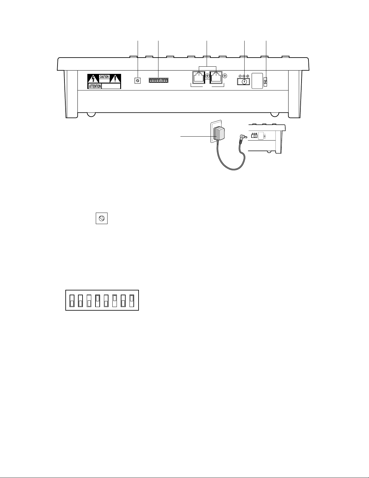
%6 Controller Number switch (CONTROLLER No.)
Selects a number for the system controller for identification in a system. Normally, set the switch to number 1.
%7 Mode Selection switches (MODE)
The operation mode of the system controller is selected
with these switches.
When you use a terminal-mode system controller, set
the switches to the positions shown in the figure.
Note: When you use a PS·Data system controller, refer
to the system controller's operating instructions.
● Rear View
^1
%8 Data ports (DATA)
Exchange the control data with the matrix switcher via
RS-485 cable (supplied with the system controller).
%9 DC 9V Input jack (DC 9V IN)
Use this jack to plug the AC adapter supplied with the
system controller.
^0 Clamp
Fastens the supplied AC adapter's power cord.
^1 AC adapter
Caution: Use only the supplied AC adapter to feed 9 V
DC to the system controller.
Note: Disconnect the plug from the controller before
setting the controller number switch or mode selection switch, and reconnect it when finished. The
new settings will take effect when the power is
turned on.
%6
0
1
9
RISK OF ELECTRIC
SHOCK. DO NOT OPEN
RISQUE DE CHOCS ELECTROUES
NE PAS OUVRIR
2
8
3
7
4
6
5
CONTROLLER No.
0
1
9
2
8
3
#1
7
4
6
5
CONTROLLER No.
%7
%9 ^0%8
DATAMODE
DC 9V IN
DC 9V IN
OFF
ON
123456 78
MODE
Page 30

30
Page 31

31
INSTALLATIONS AND SYSTEM
CONNECTIONS
Page 32

32
Notes:
• An optional cooling fan attached inside the unit is
subject to wear. It needs to be replaced periodically.
Keep the temperature in the rack below 45 °C
(113 °F) at any time.
• If the rack is subject to vibration, secure the rear of
the appliance to the rack by using additional mounting brackets (procured locally).
■ Installing the Multiplexer Board
To use WJ-HD100 Series or a time-lapse VCR as a
recorder, you need to install a Multiplexer board inside the
matrix switcher. Refer to the Multiplexer board’s operating
instructions for how to install.
INSTALLATIONS
WARNING
The installations described in the figures should be
made by qualified service personnel or system
installers.
■ Mounting into the Rack
The matrix switcher can be mounted into the rack as
described.
1. Remove the four rubber feet by unwinding the four
screws on the bottom of the matrix switcher.
2. Place the rack mounting brackets on both sides of the
matrix switcher and tighten with the four supplied
screws (M4 X10).
3. Install the matrix switcher in the rack with the rack
mounting brackets secured with four screws (procured
locally).
Remove 4 rubber feet
MUX
Page 33

33
SYSTEM CONNECTION EXAMPLES
■ Basic System Connection
This is an example of basic system connection.
Camera
16
Camera1Camera
2
Camera
3
CAMERA IN 1 to 16
ALARM IN 1 to 16
Max. 4 System Controllers
Terminal-mode PS·Data/Terminal-mode
MONITOR OUT 1 to 4
Matrix Switcher
Note: Before connecting a terminal-mode system controller to the DATA 4 port, configure the system through SETUP
MENU or WJ-SX150A Administrator Console.
■ System Expansion Connection
● Connection with Digital Disk Recorder WJ-HD500 Series or WJ-HD200 Series
When connecting the camera output connectors to Digital Disk Recorder WJ-HD500 or WJ-HD200 Series, the digital disk
recorder can record all the camera channels. More than one camera images can be displayed in multiscreen segments on the
desired monitor.
Camera
16
Camera1Camera
2
Camera
3
CAMERA IN 1 to 16
ALARM IN 1 to 16
Recorder
Max. 4 System Controllers
Terminal-mode PS·Data/Terminal-mode
MONITOR OUT 1 to 4
Available for live or play-backed camera images
(GENLOCK OFF)
Matrix Switcher
Page 34

34
Notes:
• Before connecting a terminal-mode system controller to the DATA 4 port, configure the system through SETUP MENU or
WJ-SX150A Administrator Console.
• If an optional network board is installed inside the recorder and you are to control it from LAN (local area network) or the
Internet, refer to a service manual procurable in your area.
● Connection with Digital Disk Recorder WJ-HD100 Series or Time-lapse VCR
• With the Multiplexer board, the recorded images of Camera 1 to 16 can be multiplexed to Digital Disk Recorder, WJHD100 Series or a time-lapse VCR.
To use WJ-HD100 Series or a time-lapse VCR as a recorder, you need to install a Multiplexer board inside the matrix
switcher.
MUX
Camera
Camera1Camera
2
3
Max. 16
Camera Inputs
Matrix Switcher
Recorder or Time-lapse VCR
Camera
16
16 Alarm Inputs
Multiplexer Board
WJ-SXB151
Max. 4 System Controllers 4 Monitor Outputs
Available for surveillance or playback of the camera images
Page 35

35
● Master-slave Connection
When applying this connection, up to 5 matrix switchers and 64 cameras can be connected in a surveillance control system.
One of the matrix switchers is designated as Master and the others are designated as Slave.
Camera
1
Camera
33
Camera
2
Camera
34
Camera
3
CAMERA IN
1 to 16
Matrix Switcher Matrix Switcher
Slave 1 Slave 2
Camera
35
CAMERA IN
1 to 16
Camera
16
ALARM IN
1 to 16
Camera
48
Camera
17
Camera
49
Camera
19
Camera
18
CAMERA IN
Camera
51
Camera
50
CAMERA IN
Camera
32
1 to 16
ALARM IN
1 to 16
Camera
64
1 to 16
Matrix Switcher
Slave 3 Slave 4
Matrix Switcher
ALARM IN
1 to 16
Matrix Switcher
Master
Terminal-mode PS·Data/Terminal-mode
Max. 4 System Controllers
ALARM IN
1 to 16
ALARM IN 1 to 16
MONITOR OUT 1 to 4
Page 36

36
Connect non-multiplex type cameras to the CAMERA IN
connectors 1 to 16. For cameras equipped with RS-485
communication facilities, connect the RS-485 cable as follows.
Check the camera addresses when using RS-485 cameras.
Operations from the system controller will be invalid if the
camera addresses are set improperly.
• Use addresses from 1 to 16 for individual cameras.
• Do not set the same address for more than one camera
in an RS-485 chain.
• Before connecting the RS-485 camera(s) to DATA 1, 2
and/or 3, configure the system through WJ-SX150A
Administrator Console.
■ Connection with the Camera Sites
Connect the data-multiplex type cameras (or camera site
equipment) to the CAMERA IN connectors 1 to 16 on the
matrix switcher's rear panel.
Notes:
• Make sure that the cable length is less than 900 m
(3 000 ft) between the camera site and the unit when
using RG-59/U, BELDEN 9259 or equivalent cables.
• If you use locally procured cables, it is important to use
only a data-grade cable, which is suitable for RS-485
communication (shielded 2-wire twisted cable).
• When the cable length is extended, cable compensation is available. (Refer to pp. 74 and 94.)
CONNECTIONS
IN
OUT
AUX
Alarm
7
7
RS485(CAMERA)
LINE
SELECT
24
6
6
5
5
4
4
3
3
2
2
1
1
DATA 3 DATA 2
RS485(CAMERA)
16
16
10
10
9
9
CAMERA
DATA 1
8
8
Matrix Switcher
Page 37

37
■ Connection for RS-485 Type Camera
There are two options to connect the camera with the matrix
switcher, depending on the distance between them.
One is "Home Run" wiring and the other is daisy chain
wiring. "Home Run" wiring has the transmission stability with
less transmission loss, and daisy chain wiring has connection flexibility with less data ports occupied. For data-multiplex type cameras, 900 meters (3 000 ft) is the limit to use
coaxial cable such as RG-59/U, BELDEN 9259 or equivalent.
Note: If more distance is required, use cameras and
matrix switcher with RS-485 communication feature.
Remote control becomes possible.
● "Home Run" Wiring
1. Connect with a RS-485 camera in "Home Run" wiring as
shown in the figure.
2. Set the LINE SELECT switch to 2 or 4.
Notes:
• Before connecting RS-485 cameras to DATA1 to 3, data
port setting through WJ-SX150A Administrator Console
is necessary. (Refer to p. 96 Data Port.)
• Recommended for RS-485 communication is AWG#22
or thicker one. The cable should be shielded, two-wire,
twisted pair, and with low impedance.
• Set the LINE SELECT switch to 4 when programming
preset position of WV-CSR600/650 Series camera is
connected to the unit.
● Daisy Chain Wiring
1. Draw up a plan for connection between the cameras
and the input channels of the matrix switcher, and the
assignment of unit addresses to cameras.
2. Set the LINE SELECT switch to 2. Also, set the connected device's switch if required.
3. Connect one end of the cable to RS-485 (CAMERA),
and the other end to the first camera in the chain, as
shown in the figure. Repeat this procedure for all cameras.
4. Set the termination switches of the cameras at the chain
ends to ON. Camera's termination switches must be set
to OFF except the ones at the chain ends.
Notes:
• Set the same number for the camera's unit address as
and CAMERA IN.
• Check the settings of the camera addresses when
using RS-485 cameras. Operations from the system
controller will be invalid if the camera addresses are set
improperly.
• Do not use addresses other than 1 to 16 for individual
cameras (More than 17 cameras are not allowed).
• Do not set the same address for more than one camera
in an RS-485 chain.
• Termination is the key to data transmission and reception in the chain. While the other switches are set to
OFF, only the switches at the chain ends must be set to
ON.
• The termination of this unit's RS-485 camera port is
always set to ON. Connect the unit at the end of the
daisy chain.
• The more equipment there is in the chain, the slower
the response may be.
TERM
OFF ON
(A)
OFF ON
(B)
GND
WV-CPR450 and others (For the
Termination Switch positions, refer
to the oprating instractions of the
camera.)
DATA HDR
DATA 3 DATA 2
DATA 4 DATA 1
PS•DATA
RS485(CAMERA)
Set it to
position 2.
RS485(CAMERA)
LINE
SELECT
2
4
Matrix Switcher
RS-485 type camera
Set it to
position 4.
DATA 3 D ATA 2
DATA 4
DATA HDR DATA 1
TERM
OFF ON
PS•DATA
RS485(CAMERA)
RS485(CAMERA)
LINE
SELECT
2
4
Matrix Switcher
RS485 Port
Matrix switcher's rear panel
RB
RA
TB
None
TA
TB
GND
RB
RA
TA
Page 38

38
■ Connection with the Monitors
Connect the monitors to the MONITOR OUT connectors at
the unit's rear panel with the coaxial cable.
The connectors MONITOR OUT 1 to 4 are associated to
Monitor 1 to 4. When you control the monitors from a PS·
Data controller, the connectors MONITOR OUT are associated to Unit 1 to 4.
The switch on a daisychain-connected unit
other than the
extremities must be set
to OFF.
The switch on the end
unit should be set to
ON.
(A)
(B)
GND
RS485(CAMERA)
TERM
OFF ON
(A)
(B)
GND
DATA HDR
DATA 3 DATA 2
DATA 4 D ATA 1
OFF ON
RS485(CAMERA)PS•DATA
Matrix Switcher
Auto termination works inside the matrix switcher.
OFF ON
WV-CPR450 and others
(For the termination
switch positions, refer
to the operating
instruction of the
corresponding unit.)
LINE
SELECT
2
4
Set it to 2 or 4
(the same as
the connected
equipment).
Unit address 1Unit address 2Unit address 3Unit address 4
Martix Switcher
1
3
2
4
MONITOR OUT
Monitor 1Monitor 2Monitor 4Monitor 3
Set the same
number for the
camera's unit
address as and
CAMERA IN.
16
IN
OUT
16
DATA 3 DATA 2
DATA 1
RS485(CAMERA)
7
8
9
10
7
8
9
10
CAMERA
5
6
5
6
3
4
3
4
1
2
1
2
Matrix Switcher
Page 39

39
■ Connection with the Alarm Sensors
Connect the sensor switches to the unit's alarm port, as
shown in the example.
Notes:
• Alarm inputs that are simultaneous or with very short
intervals will be ignored.
Allow for at least 100 ms interval from one alarm input to
the next.
• Confirm the alarm sensor type (N.O. or N.C.) and configure the system through SETUP MENU (OSD) or WJSX150A Administrator Console.
The factory setting is N.O.
N.O.: Normally Open alarm contact
N.C.: Normally Closed alarm contact
• Alarm pins assigned as the time adjusting (TIME) terminals cannot be used as alarm input terminals.
• The specification of Recover Input: 5 V DC / 0 V (low-
active)
Recover Input, which resets alarm signals, is Pin No. 13
of the ALARM port. To reset alarm signals, contact GND
and Recover Input.
When you connect Digital Disk Recorder WJ-HD100
Series to the matrix switcher, set the recorder's alarm
polarity to Open-collector low by setting the MODE
switch #6 to off.
■ Connection with the System Controllers
Connect the system controller to the DATA 1 to 4 port at the
unit's rear panel with the modular cable.
Notes:
• Up to four system controllers are connectable.
• Connect them in home run.
• In the factory default setting, the DATA 4 port is a
PS·Data terminal. To connect a terminal-mode system
controller to this port, you need to change the data port
setting through SETUP MENU or WJ-SX150A
Administrator Console. (Refer to pp. 74 or 96.)
RS485(CAMERA)
LINE
SELECT
2
4
Matrix Switcher
TERM
OFF ON
DATA 3 D ATA 2
DATA 4DATA HDR DATA 1
RS485(CAMERA)PS•DATA
System controllerSystem controller
DATA1 to DATA4 Port
Matrix switcher's rear panel
DATA 1 to 4
GND
TA
TB
GND
RB
RA
RB
RA
TB
TA
Recover
Input
13
ALARM
Pin No. Designation
1
2
3
4
5
6
7
8
9
10
11
12
13
25
Alarm Input 1
Alarm Input 3
Alarm Input 5
Alarm Input 7
Alarm Input 9
Alarm Input 11
Alarm Input 13
Alarm Input 15
GND
Alarm Output 1
Alarm Output 3
GND
Recover Input
Alarm
Sensor 1
Alarm
Sensor 2
1
14
Pin No. Designation
14
15
16
17
18
19
20
21
22
23
24
25
Alarm Input 2
Alarm Input 4
Alarm Input 6
Alarm Input 8
Alarm Input 10
Alarm Input 12
Alarm Input 14
Alarm Input 16
GND
Alarm Output 2
Alarm Output 4
GND
Page 40

40
■ Connection with Digital Disk Recorder WJ-HD500 Series
Note: Refer to a service manual procurable in your area, for
details on the connection with a recorder (after the network board installation) to operate via LAN or the
Internet.
● To Confirm the Images from a
Recorder Connected to the Unit
The following is the description of the connection between a
recorder and this unit to confirm the images from the
recorder.
1. Set the unit address of the recorder to 1. Then, confirm
that the recorder’s CAMERA GENLOCK is set to OFF in
its SETUP MENU. (Refer to the recorder's operating
instructions.)
2. Connect the unit’s CAM OUT 1 to 16 connectors to the
recorder’s VIDEO IN 1 to 16 connectors with a coaxial
cable.
3. Connect the unit’s EXT IN connector to the recorder’s
MULTI SCREEN OUT connector with a coaxial cable.
4. Connect the unit’s DATA HDR connector to the
recorder’s DATA port with a modular cable.
(The control data and alarm signal will be output from
the unit to the recorder.)
Notes:
• You cannot record the camera images in maximum
recording rate through this connection. Refer to the next
connection example in this page.
■ Connection with the Alarm Output
Pins #10, 11, 23 and 24 (open collector) turns to 0 V while
the alarm is activated. These terminals can drive external
warning devices such as a buzzer or lamp of up to 100 mA,
16 V DC. If the rating exceeds 100 mA, 16 V DC use a relay
as shown in Example 2.
Alarm signals are output from the terminals until the reset.
Example 1: Direct drive connection
Example 2: Connection of devices exceeding drive
Note: An alarm signal is output from the Master unit and a
unit activated by the alarm. Be careful of connections
as the Master unit outputs alarm signals to directly-connected devices any time when an alarm is activated.
Buzzer
NC
NO
To Buzzer
C
Relay
+12V
GND
NC: Normally Closed Contact
NO: Normally Open Contact
C: Common
Monitor
Matrix Switcher
16
IN
OUT
OFF ON
TERM
SERIALALARM
DATA 3 DATA 2
DATA 4DATA HDR DATA 1
RS485(CAMERA)PS•DATA
CAMERA
RS485(CAMERA)
SELECT
2
EXT IN
EXT IN
(PLAY IN)
CAMERA
SW IN
LINE
4
EXT OUT
(REC OUT)
44556677889910101111121213131414151516
MONITOR OUT
3
MONITOR
OUT
143
2
11223
DATA HDR
MULTI SCREEN
OUT
IN EXT STORAGE COPY
SPOT
OUT
OUT
MULTI SCREEN OUT
IN
OUT
CONTROL ALARM
AUDIO
16161515141413131212111110109988776655443 2
VIDEO
GEN-LOCK OUT
SIGNAL GND
REMOTE(WV-CU50)
DATA
MODE
10/100BASE-T
SERIAL
1
2
1
3
Recorder
Page 41

41
● To Record the Camera Images in Maximum
Recording Rate
The following is the description of the connection between a
recorder and this unit for the maximum-rate recording.
1. Set the unit address of the recorder to 1. Then, set the
recorder’s CAMERA GENLOCK to ON in its SETUP
MENU. (Refer to the recorder's operating instructions.)
2. Connect the unit’s CAM OUT 1 to 16 connectors to the
recorder’s VIDEO IN 1 to 16 connectors with a coaxial
cable.
3. Connect the unit’s EXT IN connector to the recorder’s
GENLOCK OUT connector with a coaxial cable.
4. Connect the unit’s DATA HDR connector to the
recorder’s DATA port with a modular cable.
(The control data and alarm signal will be output from
the unit to the recorder.)
5. After the connection, set the unit’s EXT IN to GENLOCK
ON through SETUP MENU or WJ-SX150A Administrator
Console (Refer to pp. 71 or 97).
Notes:
• You need WJ-HD500A or a newer model for the maximum-rate recording.
• The playback, multiscreen output or live images from the
recorder are not displayed on Monitor 1 to 4. To confirm
the images, you need to connect another monitor with
the recorder.
• The recorder will not operate if its unit address is set to
other than 1.
• Make sure the recorder’s unit address is set to 1
through SETUP MENU or WJ-SX150A Administrator
Console. (Refer to pp. 71 or 97.) If another number is
selected, you cannot control the recorder.
• Make sure the recorder’s unit address is set to 1
through SETUP MENU or WJ-SX150A Administrator
Console. (Refer to pp. 71 or 97.) If another number is
selected, you cannot control the recorder.
LINE
SELECT
CAMERA
4
GEN-LOCK OUT
REMOTE(WV-CU50)
SERIAL
(PLAY IN)
SW IN
EXT IN
EXT OUT
(REC OUT)
44556677889910101111121213131414151516
SIGNAL GND
3
EXT IN
143
2
MONITOR OUT
3
11223
10/100BASE-T
1
2
1
GENLOCK
OUT
MULTI
SCREEN
OUT
Matrix Switcher
16
IN
OUT
OFF ON
RS485(CAMERA)PS•DATA
CAMERA
SERIALALARM
DATA 3 DATA 2
DATA 4DATA HDR DATA 1
TERM
DATA HDR
DATA
IN EXT STORAGE COPY
SPOT
OUT
OUT
MULTI SCREEN OUT
IN
OUT
CONTROL ALARM
AUDIO
16161515141413131212111110109988776655443 2
DATA
MODE
VIDEO
Recorder
RS485(CAMERA)
2
Monitor
Page 42

42
● To Control a Recorder via the
Network
The following is the description of the connection between
a recorder and this unit to control the recorder via the network.
1. Set the recorder's unit address to a number 5 or larger .
(Refer to the recorder's operating instructions.)
2. Connect the unit’s CAM OUT 1 to 16 connectors to the
recorder’s VIDEO IN 1 to 16 connectors with a coaxial
cable.
3. Connect the unit’s DATA HDR and DATA4 connectors
to the recorder’s DATA port with a daisy chain connection cable kit (WV-CA48/10K).
(The control data and alarm signal will be output from
the unit to the recorder.)
4. Select the recorder’s new unit address, which is set in
Step 1, in 600 RECORDER (refer to p. 71 ) of SETUP
MENU or the Recorder (refer to p. 97 ) window of WJSX150A Administrator Console.
5. Through a browser, set the unit address of an optional
network board (WJ-HDB502) to a number other than 1.
(Refer to WJ-HDB502 Operating Instructions.)
6. Refer to p. 38, p. 40 and p. 41 for MONITOR OUT connection, MULTI SCREEN OUT connection, and EXT IN
connection.
Notes:
• You will need WJ-HD500A or a newer model, in which
an optional network board (WJ-HDB502) is installed.
• Select the PS·Data protocol for the DATA 4 setting.
(Refer to p. 74 CAMERA/DATA1 - 4 PORT or p. 96 Data
Port.) If the terminal mode is selected, you cannot control the recorder.
• The recorder will not be operable if its unit address is
set to 1/2/3/4.
• If the recorder's unit address in Step 1 and the recorder
setting in Step 4 are different, the recorder will not be
operable.
• In these connections, you cannot use a PS·Data system
controller.
Matrix Switcher
OFF ON
16
IN
OUT
DATA HDR
RS485(CAMERA)PS•DATA
CAMERA
DATA4
(PS·Data)
SERIALALARM
DATA 3 DATA 2
DATA 4DATA HDR DATA 1
TERM
Daisy Chain Connection Kit
(WV-CA48/10K)
MULTI SCREEN
OUT
IN EXT STORAGE COPY
SPOT
OUT
OUT
AUDIO
CONTROL ALARM
MULTI SCREEN OUT
16161515141413131212111110109988776655443 2
IN
OUT
DATA
MODE
VIDEO
DATA
RS485(CAMERA)
2
LINE
SELECT
Monitor
EXT IN
EXT IN
(PLAY IN)
CAMERA
SW IN
4
EXT OUT
(REC OUT)
GEN-LOCK OUT
REMOTE(WV-CU50)
SERIAL
44556677889910101111121213131414151516
3
SIGNAL GND
3
2
MONITOR OUT
10/100BASE-T
1
1
MONITOR
OUT
143
2
11223
10/100 BASE-T
Recorder*
LAN Cable
HUB/Router
LAN**
* WJ-HD500A or Newer Models with Network Board (WJ-HDB502)
** LAN : Local Area Network
Page 43

43
■ Connection with Digital Disk Recorder WJ-HD200 Series
Note: Refer to a service manual procurable in your area, for details on the connection with a recorder to operate via LAN or the
Internet.
● To Confirm the Images from a Recorder Connected to the Unit
The following is the description of the connection between a recorder and this unit to confirm the images from the recorder.
1. Set the unit address of the recorder to 1. (Refer to the recorder's operating instructions.)
2. Connect the unit’s CAM OUT 1 to 8 connectors to the recorder’s VIDEO IN 1 to 8 connectors with a coaxial cable.
3. Connect the unit’s EXT IN connector to the recorder’s MULTI SCREEN OUT connector with a coaxial cable.
4. Connect the unit’s DATA HDR connector to the recorder’s DATA port with a modular cable.
(The control data and alarm signal will be output from the unit to the recorder.)
Notes:
• If you use two WJ-HD200 Series recorders, you cannot control the recorders with the system controller connected to the
Master unit. When recording the images from CAM IN 1 to 16, it is recommended to use WJ-HD500 Series recorders.
• Make sure the recorder’s unit address is set to 1 through SETUP MENU or WJ-SX150A Administrator Console. (Refer to pp.
71 or 97.) If another number is selected, you cannot control the recorder.
Monitor
Matrix Switcher
16
IN
OUT
OFF ON
DATA HDR
EXT IN
RS485(CAMERA)
SELECT
2
(PLAY IN)
CAMERA
SW IN
LINE
4
EXT OUT
(REC OUT)
44556677889910101111121213131414151516
SERIALALARM
DATA 3 DATA 2
DATA 4DATA HDR
TERM
PS•DATA
DATA 1
RS485(CAMERA)
CAMERA
3
3
MONITOR OUT
MONITOR OUT
EXT IN
214
11223
CAMERA
SIGNAL GND
POWER
AC IN
OUT 1 to 8
VIDEO IN
1 to 8
IN
OUT
AUDIO
MULTI
SCREEN OUT
IN
VIDEO
1
SPOT
OUT
ALARM/REMOTE
1
22334455667788OUT
MULTI
SCREEN OUT
(WV-CA48/10K)
DATA
DATA10/100BASE-TMODERS-232C
POWER
ON
SIGNAL GND
OFF
Recorder
Page 44

44
● To Control a Recorder via the Network
The following is the description of the connection between a recorder and this unit to control the recorder via the network.
1. Set the recorder's unit address to a number 5 or larger . (Refer to the recorder's operating instructions.)
2. Connect the unit’s CAM OUT 1 to 8 connectors to the recorder’s VIDEO IN 1 to 8 connectors with a coaxial cable.
3. Connect the unit’s EXT IN connector to the recorder’s MULTI SCREEN OUT connector with a coaxial cable.
4. Connect the unit’s DATA HDR and DATA4 connectors to the recorder’s DATA port with a daisy chain connection cable kit
(WV-CA48/10K).
5. Select the recorder’s new unit address, which is set in Step 1, in 600 RECORDER (refer to p. 71 ) of SETUP MENU or the
Recorder (refer to p. 97) window of WJ-SX150A Administrator Console.
6. Through a browser or the recorder’s SETUP MENU, set the CTL-UNIT ADDR to a number other than 1. (Refer to the
recorder’s operating instructions.)
Notes:
• Select the PS·Data protocol for the DATA 4 setting. (Refer to p. 74 CAMERA/DATA1 – 4 PORT or p. 96 Data Port.) If the terminal mode is selected, you cannot control the recorder.
• The recorder will not be operable if its unit address is set to 1/2/3/4.
• If the recorder's unit address in Step 1 and the recorder setting in Step 5 are different, the recorder will not be operable.
• In these connections, you cannot use a PS·Data system controller.
• If you use two WJ-HD200 Series recorders, you cannot control the recorders with the system controller connected to the
Master unit. When recording the images from CAM IN 1 to 16, it is recommended to use WJ-HD500 Series recorders.
Monitor
Matrix Switcher
16
IN
OUT
VIDEO IN
1 to 8
IN
OUT
AUDIO
Recorder
DATA HDR
IN
TERM
OFF ON
DATA 4DATA HDR
PS•DATA
DATA 4
(PS•DATA )
VIDEO
DATA 3 DATA 2
CAMERA
SERIALALARM
RS485(CAMERA)
22334455667788OUT
RS485(CAMERA)
DATA 1
1
1
SCREEN OUT
EXT IN
(PLAY IN)
CAMERA
SW IN
LINE
SELECT
2
4
EXT OUT
(REC OUT)
44556677889910101111121213131414151516
MULTI
SCREEN OUT
SPOT
OUT
ALARM/REMOTE
MULTI
MONITOR OUT
3
EXT IN
214
MONITOR OUT
3
11223
CAMERA
OUT 1 to 8
(WV-CA48/10K)
DATA
DATA10/100BASE-TMODERS-232C
POWER
ON
OFF
LAN Cable
LAN *
HUB/Router
* LAN: Local Area Network
SIGNAL GND
POWER
AC IN
SIGNAL GND
Page 45

45
■ Connection with Digital Disk Recorder WJ-HD100 Series
1. To record the camera images with Digital Disk Recorder WJ-HD100 Series, install an optional Multiplexer board in the
matrix switcher.
2. Connect the matrix switcher’s EXT OUT (REC OUT) to the digital disk recorder’s VIDEO IN with a coaxial cable.
3. Connect the matrix switcher’s EXT IN (PLAY IN) to the digital disk recorder’s MONITOR OUT (PLAY) with a coaxial cable.
4. Connect the matrix switcher’s DATA HDR to the digital disk recorder’s DATA with a modular cable.
5. Connect the matrix switcher’s CAMERA SW IN to the digital disk recorder’s CAMERA SW OUT with an RCA-pin cable.
6. Select “HD100” for 600 RECORDER in SETUP MENU. (Refer to p. 71.)
7. Conform the parameter of 740 CAMERA/DATA 1 - 4 PORT to the setting of the recorder.
The following parameters are fixed.
Data bit: 8 bits
Parity check: None
Stop bit: 1 bit
8 Conform the parameter of 620 RECORDER UNIT ADDRESS in SETUP MENU to the setting of the recorder. (Refer to the
recorder’s operating instructions for the unit address.)
Note: After the connection, configure the system through SETUP MENU and WJ-SX150A Administrator Console.
● DATA HDR Port
(
)
MUX
Pin #10 (Alarm Out 1)
Pin #11 (Alarm Out 3)
Pin #13
(Recover Input)
Matrix Switcher
Pin #24 (Alarm Out 4)
Pin #23 (Alarm Out 2)
Pin #9 (GND)
TERM
OFF ON
PS•DATA
EXT IN
RS485(CAMERA)
2
SELECT
(PLAY IN)
CAMERA
SW IN
LINE
4
EXT OUT
REC OUT
SERIALALARM
DATA 3 D ATA 2
DATA 4DATA HDR
DATA 1
RS485(CAMERA)
3
MONITOR OUT
214
Matrix switcher's rear panel
DATA HDR
GND
RA
RB
IN
IN
OUT
OUT
CAMERA
SW OUT
MONITOR OUT
AUDIO
Recorder
ON
1234 56
DATA HDR Port
GND
TB
TA
(PLAY)
MODE
G
ALARM SEARCH
STEP
REMOTE
REW/FF
STOP/SETUP
G
PLAY
REC
ADJUST
JOG-CLICK
JOG-LEFT
JOG-RIGHT
(EXT REC)
MODEDATARS-232CVIDEO
Set the recorder’s alarm
polarity to Open-collector
low by setting the MODE
switch #6 to OFF.
Polarity switch
TB
TA
RB
RA
POWER
ON
G
OUT
PLAY OUT
REC OUT
AUTO OFF OUT
DISK END OUTINOUTINRECALL
OUT
RECOVER OUT
RESET IN
IN
SERIES
TIME
RECORD
ALARM
SIGNAL GND
OFF
Page 46

46
■ Connection with the Time-lapse VCR (Panasonic Models)
1. Configure the parameters of the Multiplexer functions in the Multiplexer Mode (refer to p. 98) window of WJ-SX150A
Administrator Console.
Note: To put a file from PC to the unit, select PC in 600 RECORDER in SETUP MENU. (Refer to p. 71.) When VCR is select-
ed, parameter configuration in the Multiplexer Mode window is unavailable.
2. After Step 1, select VCR for 600 RECORDER in SETUP MENU. (Refer to p. 71.)
3. Conform the communication speed (SPEED) for 740 CAMERA/DATA 1- 4 PORT in SETUP MENU to that of the time-lapse
VCR. (Refer to pp. 74 and 75.)
The following parameters are fixed.
Data bit: 7 bits
Parity check: ODD
Stop bit: 1 bit
4. Connect the matrix switcher’s EXT OUT (REC OUT) to the time-lapse VCR’s VIDEO IN with the coaxial cable.
5. Connect the matrix switcher’s EXT IN (PLAY IN) to the time-lapse VCR’s VIDEO OUT with the coaxial cable.
6. Connect the matrix switcher’s SERIAL to that of the time-lapse VCR with a 9-pin D-sub cable.
7. Connect the matrix switcher’s CAMERA SW IN to the time-lapse VCR’s CAMERA SW OUT with an RCA-pin cable.
Notes:
• Only Panasonic time-lapse VCRs which support RS-232C are usable. (Refer to Cable Specifications on the next page
for details of cables.)
• Both of the time-lapse VCR and PC cannot be connected to the matrix switcher.
• When configuring the system through WJ-SX150A Administrator Console, pull out the time-lapse VCR’s cable and con-
nect the PC’s cable to the serial port.
• To use the alarm recording function, connect the matrix switcher’s all alarm output terminals (Alarm Output 1 to 4) to
the time-lapse VCR’s ALARM IN.
• Be sure to activate auto-recovery for the VCR’s alarm reset function.
(
)
MUX
Pin #13
(Recover Input)
Pin #10(Alarm out 1)
Pin #11(Alarm out 3)
TERM
OFF ON
Pin #24(Alarm out 4)
PS•DATA
DATA 3 D ATA 2
DATA 4DATA HDR
SERIALALARM
RS485(CAMERA)
DATA 1
Matrix Switcher
EXT IN
(PLAY IN)
CAMERA
RS485(CAMERA)
SW IN
LINE
SELECT
2
4
EXT OUT
REC OUT
Pin #23(Alarm out 2)
Pin #9(GND)
VIDEO IN
GND
CAMERA
SW OUT
S-VIDEO
AUDIO
2
1
VIDEO OUT
4
Time-lapse VCR
1 2 3 4 5 6 7 8 9 10 11 12 13 14 15 16
ALARM
1
IN
COM
2
ALARM
3
RESET IN
ALARM
4
RECOVER OUT
ALARM
5
OUT
1 SHOT IN
6
7
COM REC OUT
TAPE END
8
OUT
WARNING
9
HUMID OUT
10
11
REC REVIEW
12
OUT
OUT
13
14
15
ADJUST IN
16
ADJUST OUT
MONITOR OUT
SERIES
REC IN
SERIES
REC OUT
TIME
TIME
3
214
Page 47

47
■ Connection with the Time-lapse VCR (Non-Panasonic Models)
1. To record the camera images through a time-lapse VCR, install an optional Multiplexer board in the matrix switcher.
2. Select OFF for 600 RECORDER in SETUP MENU. (Refer to p. 71.)
3. Connect the matrix switcher’s EXT OUT (REC OUT) to the time-lapse VCR’s video input connector with the coaxial cable.
4. Connect the matrix switcher’s EXT IN (PLAY IN) to the time-lapse VCR’s video output connector with the coaxial cable.
Notes:
• To use the alarm recording function, connect the matrix switcher’s all alarm output terminals (Alarm Output 1 to 4) to the
time-lapse VCR’s ALARM IN.
• Be sure to set the VCR to automatically recover from alarm reset.
(
)
● Cable Specifications
1
2
3
4
5
6
7
8
9
Frame
1
2
3
4
5
6
7
8
20
22
Frame
Shield
Time-lapse VCRMatrix Switcher
AG6730, AG6740
1
2
3
4
5
6
7
8
9
1
2
3
4
5
6
7
8
9
Straight Cable
RT850Matrix Switcher
RT850
MUX
Pin #10(Alarm out 1)
Pin #13
(Recover Input)
Pin #11(Alarm out 3)
TERM
OFF ON
Pin #24(Alarm out 4)
Pin #23(Alarm out 2)
Pin #9(GND)
VIDEO IN
CAMERA
SW OUT
GND
DATA 4DATA HDR
PS•DATA
S-VIDEO
AUDIO
DATA 3 D ATA 2
VIDEO OUT
Matrix Switcher
SERIALALARM
RS485(CAMERA)
DATA 1
LINE
SELECT
RS485(CAMERA)
2
Time-lapse VCR
EXT IN
(PLAY IN)
CAMERA
SW IN
4
EXT OUT
REC OUT
3
MONITOR OUT
214
2
1
4
1 2 3 4 5 6 7 8 9 10 11 12 13 14 15 16
ALARM
1
IN
COM
2
ALARM
3
RESET IN
ALARM
4
RECOVER OUT
ALARM
5
OUT
1 SHOT IN
6
7
8
TAPE END
10
11
COM REC OUT
12
OUT
WARNING
9
OUT
HUMID OUT
REC REVIEW
OUT
SERIES
13
SERIES
14
REC OUT
15
ADJUST IN
16
ADJUST OUT
REC IN
TIME
TIME
Page 48

48
■ Connection with the PC
1. Conform the communication speed (SERIAL PORT
SPEED) parameter in SETUP MENU to that of the PC.
2. Connect the matrix switcher's serial port to that of the
PC with the 9-pin D-sub cable.
Notes:
• The following parameters are fixed.
Data bit: 8 bits
Parity check: none
Stop bit: 1 bit
• Refer to Cable Specifications in this page for details on
cables.
● Cable Specifications
■ Time Adjustment with an External
Equipment
The specified external devices can output the time adjusting signal to the matrix switcher.
This signal can adjust the time by up to ± 30 seconds every
hour.
To use this function, it is necessary to assign the alarm
input terminal(s) (pin # 1 to 16) to the time adjusting terminal(s).
SETUP MENU or WJ-SX150A Administrator Console can
assign the signal.
Note: In the master-slave connection, time setting of every
unit can be synchronized when the time adjusting signal is input to any unit.
● Master Clock Connection Example
for Time Adjustment
Connect the matrix switcher's time adjusting terminal to
those of the master clock with the twisted pair cable.
The figure below shows the case in which Alarm Input 16 is
assigned as the time adjusting terminal.
Note: A master clock with N.O. (Normally Open alarm con-
tact)-type output is connectable.
D-sub9
or
D-sub25
Personal Computer Matrix Switcher
D-sub9
SERIAL
PC Matrix Switcher
1
2
3
4
5
6
7
8
Frame
Shield
1
2
3
4
5
6
7
8
Frame
Matrix Switcher
ALARM
Pin #22
GND
Pin #21
12
39
6
Master clock
Page 49

49
■ Master-slave Connection
The following are master-slave connection patterns.
Pattern 1: Master and Slave 1 are connected in the system.
16
16
Slave 1
Camera 1 to 16
HDR PSD D3 D2 D1 CAM
REC
FS
16
Digital Disk
Recorder
WJ-HD A
Master
MON1→CAM1
MON2→CAM2
MON3→CAM3
MON4→CAM4
•
Data
PS
Camera 17 to 28
HDR D3 D2 D1 CAM
PSD
MONITOR OUT 1 to 4
REC
FS
16
Digital Disk
Recorder
WJ-HD A
Terminal - mode
Page 50

50
Pattern 2: Master, Slave 1 and 2 are connected in the system.
16
16
16
Slave 1
Camera 1 to 16
HDR PSD D3 D2 D1 CAM
MON1→CAM1
MON2→CAM2
MON3→CAM3
MON4→CAM4
REC
FS
16
Digital Disk
Recorder
WJ-HD A
MON1→CAM5
MON2→CAM6
MON3→CAM7
MON4→CAM8
Slave 2
Camera 17 to 32
HDR PSD D3 D2 D1 CAM
REC
FS
16
Digital Disk
Recorder
WJ-HD A
Master
Camera 33 to 40
PS
•
Data
HDR D3 D2 D1 CAM
PSD
MONITOR OUT 1 to 4
REC
FS
16
Digital Disk
Recorder
WJ-HD A
Terminal - mode
Page 51

51
Pattern 3: Master, Slave 1 to 3 are connected in the system.
16
16
16
16
Slave 1
Camera 1 to 16
HDR PSD D3 D2 D1 CAM
MON1→CAM1
MON2→CAM2
MON3→CAM3
MON4→CAM4
REC
FS
16
Digital Disk
Recorder
WJ-HD A
MON1→CAM5
MON2→CAM6
MON3→CAM7
MON4→CAM8
Slave 2
Camera 17 to 32
HDR PSD D3 D2 D1 CAM
REC
Slave 3
Camera 33 to 48
HDR PSD D3 D2 D1 CAM
FS
16
Digital Disk
Recorder
WJ-HD A
REC
FS
16
Digital Disk
Recorder
WJ-HD A
Master
Camera 49 to 52
MON1→CAM9
MON2→CAM10
MON3→CAM11
MON4→CAM12
PS
•
Data
HDR D3 D2 D1 CAM
PSD
MONITOR OUT 1 to 4
REC
FS
16
Digital Disk
Recorder
WJ-HD A
Terminal - mode
Page 52

52
Pattern 4: Master, Slave 1 to 4 are connected in the system.
Note: Before connections, make sure all the units have the same firmware version. You can see the firmware version of each
unit in SETUP MENU. (Refer to pp. 72 and 73 710 MASTER-SLAVE.) In case there is a version difference, update the
firmware of each unit to the newest using a CD-ROM. (Refer to pp.58 to 60 FIRMWARE UPDATE.)
● Preparation
Prepare the following items besides standard accessories.
• Personal computer x 1 (Refer to p. 79 Platform for details on system requirements.)
• 9-pin D-sub crossing cable x 1 (Used for connection between the PC and the Master unit)
• Phillips screwdriver x 1 (Used for opening the front panel and setting unit numbers)
• Coaxial cable* (Used for connection of the Master and Slave units)
• Cable Kit WV-CA48/10K* (Used for connection of more than one Slave unit)
* Necessary number will differ depending on the connection pattern.
● Unit Number Selection
Set the unit number selector of each unit to determine Master and slave n*. (Refer to the illustration and diagram in p. 24.)
*n is a unit number.
16
16
16
16
Slave 1
Camera 1 to 16
HDR PSD D3 D2 D1 CAM
MON1→CAM1
MON2→CAM2
MON3→CAM3
MON4→CAM4
REC
FS
16
Digital Disk
Recorder
WJ-HD A
MON1→CAM5
MON2→CAM6
MON3→CAM7
MON4→CAM8
Slave 2
Camera 17 to 32
HDR PSD D3 D2 D1 CAM
Slave 3
Camera 33 to 48
HDR PSD D3 D2 D1 CAM
REC
FS
16
Digital Disk
Recorder
WJ-HD A
REC
FS
16
Digital Disk
Recorder
WJ-HD A
Slave 4
Camera 49 to 64
HDR PSD D3 D2 D1 CAM
REC
FS
16
Digital Disk
Recorder
WJ-HD A
Master
MON1→CAM9
MON2→CAM10
MON3→CAM11
MON4→CAM12
MON1→CAM13
MON2→CAM14
MON3→CAM15
MON4→CAM16
HDR D3 D2 D1 CAMPSD
MONITOR OUT 1 to 4
PS
•
Data
Terminal - mode
Page 53

53
● Video Cable Connection
Connect the camera input connectors of Master and the monitor output connectors of Slave with coaxial cables as described
in the diagram.
● DATA Port Connection
• Connect the DATA 3 port of the Master unit and the DATA 4 port of the Slave units.
• Connect the Master and Slave units with the supplied crossing cable.
• Connect Slave and Slave with Cable Kit WV-CA48/10K.
• Set the termination selectors of the Master and terminal Slave unit to ON.
• Set the termination selectors of other Slave units to OFF.
• Connect system controllers to the Master unit. (Refer to p. 39.)
Note: System controllers cannot be connected to Slave units.
Connection Master Slave
Master and Slave 1
Master and Slave 2
Camera Input 1 Monitor Output 1
Camera Input 2 Monitor Output 2
Camera Input 3 Monitor Output 3
Camera Input 4 Monitor Output 4
Camera Input 5 Monitor Output 1
Camera Input 6 Monitor Output 2
Camera Input 7 Monitor Output 3
Camera Input 8 Monitor Output 4
Monitor Output 1
Monitor Output 2
Monitor Output 3
Monitor Output 4
Monitor Output 1
Monitor Output 2
Monitor Output 3
Monitor Output 4
Master and Slave 3
Camera Input 9
Camera Input 10
Camera Input 11
Camera Input 12
Master and Slave 4
Camera Input 13
Camera Input 14
Camera Input 15
Camera Input 16
Example: Master, Slave 1 and 2 are connected in the system.
Slave 1 Slave 2
TERM
OFF ON
Connect the side
marked as “Slave”
to the DATA 4 port
of Slave 1.
Master
TERM
OFF ON
DATA 4DATA HDR
OFF ON
PS•DATA
Cable Kit WV-CA48/10K
Cable Kit WV-CA48/10K
DATA 4DATA HDR
DATA 3
TERM
Crossing cable
(supplied to the unit)
DATA 4DATA HDR
PS•DATA
PS•DATA
Connect the side marked as
“Master” to the DATA 3 port
of Master.
Page 54

54
Connect the cameras and the Master/Slave 1 to 4 with the coaxial cables according to the diagram.
● Recorder Connection
Connect recorders to each Master/Slave units. Refer to pp. 40 to 47 for connection procedures.
Example: Master, Slave 1 and 2 are connected in the system.
Notes:
• Recorders and/or the Multiplexer board cannot be connected to the Master unit when Slave 1 to 4 are connected in the
system.
• The Master unit’s camera channels which loop thru Slave units cannot be connected to the recorder. (In the illustration, the
Master unit’s CAM OUT 1 to 8 and the recorder’s VIDEO IN 1 to 8 cannot be connected.) The Master recorder can record
only images from directly-connected cameras when the Master and Slave 1/2/3 are connected together. (For example in
the illustration, the Master recorder can record images from Cam 33 to 40.) Camera input signals from Slave units to the
Master unit are not for recording but for cross point switching.
● Connection between the Units and Cameras
Connect each camera to CAMERA IN 1 to 16 of each unit. (Refer to p. 36 Connection with the Camera Sites.) Each camera has
its own logical camera number.
The default setting of the logical camera numbers is as follows. (The logical camera numbers can be configured in SETUP
MENU and WJ-SX150A Administrator Console.)
Camera total
number
1 to 16
17 to 28
29 to 40
41 to 52
53 to 64
1 to 16
17 to 28
33 to 40
49 to 52
–
–
1 to 16
1 to 16
1 to 16
1 to 16
–
–
17 to 32
17 to 32
17 to 32
–
–
–
33 to 48
33 to 48
–
–
–
–
49 to 64
Cameras connected
to Master
Cameras connected
to Slave 1
Cameras connected
to Slave 2
Cameras connected
to Slave 3
Cameras connected
to Slave 4
Camera
Master unit
40 39 38 37 36 35 34 33
11
12
13
14
15
16
IN
Connected to Slave 2 Connected to Slave 1
4
5
6
7
8
9
10
1
2
3
Master recorder
OUT
IN
OUT
15
16
1616151514141313121211111010998
13
14
11
12
3
4
5
6
7
8
9
10
CAMERA
7
6
5
4
3 2
8
7
6
5
VIDEO
4
1
2
1
23
1
Page 55

55
● Connection with the PC
Connect the PC and the Master unit. (Refer to p. 48 for the
connection procedure.)
● Software Setup
After connecting the PC to the Master unit, do the setup
procedure with SETUP MENU or WJ-SX150A Administrator
Console.
• With SETUP MENU
1. Turn the power of each unit to ON.
2. Log-in the system with a system controller. (Refer to p.
104.)
3. Open SETUP MENU. (Refer to p. 63.)
4. Open “700 SYSTEM” - “710 MASTER-SLAVE”. (Refer to
pp. 72 and 73.)
5. Set the connected Slave units to ON. “Is the MASTERSLAVE changed? NO” will appear.
6. Change NO to YES by pressing the NEXT or PREV button on the system controller.
7. Press the SET button. The setting will be saved and you
will log-out from SETUP menu.
• With WJ-SX150A Administrator Console
1. Turn the power of each unit to ON.
2. Open WJ-SX150A Administrator Console. (Refer to p.
80.)
3. Open the Master-Slave window. (Refer to p. 81.)
4. Configure and save the settings by clicking on the Save
Exit button. (Refer to p. 82.)
5. Open the “Put a file to SX150A” window. (Refer to p.
83.)
6. Click on the “OK” button. The setting data will be transferred to the Master unit.
7. Close the main window (refer to p. 80) to quit WJSX150A Administrator Console.
● Recorder Setup
When connecting a recorder with more than one video
input (WJ-HD500 or WJ-HD200 Series), conform the LCN
(logical camera number) settings of the unit to the camera
number setting of a recorder. (Refer to pp. 73/82 and the
recorder’s operating instructions.)
Page 56

56
Page 57

57
WJ-SX150A SETUP PROCEDURES
Page 58

58
FIRMWARE UPDATE
This setting is required when there is a firmware version difference among each unit in the master-slave connection.
Before the procedure, confirm the versions written on the
label on each CD-ROM.
■ Installation of SX150A Program Writer
Note: Refer to p. 79 for the platform necessary for installa-
tion.
1. Insert the supplied CD-ROM into the PC.
2. Open the CD-ROM drive window.
The file is located in the following directory.
E: \PWriter\SetupPWriter.exe (E is the CD-ROM drive.)
3. Double-click the “SetupPWriter.exe” icon to begin the
installation. The Welcome window will appear on the PC
screen.
4. Press the NEXT button to continue the installation.
5. Respond to the dialog boxes by following the directions
given.
■ Firmware Update of SX150A Program Writer
1. Connect the matrix switcher's serial port to that of the
PC with the 9-pin D-sub cable. (Refer to p. 48.)
2. Launch SX150A Program Writer by selecting “Start” –
“Programs” – “Panasonic” – “SX150A Program Writer”.
The RS232C Setting window will appear on the PC
screen.
3. Confirm whether the following are selected.
Then, click on "SET".
Baud Rate: 38400
Data Bit: 8
Parity: NONE
Stop Bit: 1
Com Port: 1 (Select the usable communication-port
number of the PC.)
Note: Conform the baud rate to the SERIAL port setting
in 740 CAMERA/DATA 1 - 4 PORT. (Refer to pp. 74
and 75.) The factory default setting is 38400 bps.
4. Set the mode selector at the front panel as shown in the
Version confirmation mode window. Besides, make sure
the unit number selector is set to “0”.
In case you have changed the selector settings, do the
following after Step 4.
(1) Turn off the unit.
(2) Turn on the unit again.
Page 59

59
5.Click on the OK button in Version confirmation mode window.
Note: If the selector settings are wrong when you do
Step 5, the following message will appear to notify
that version confirmation was failed.
In this case, confirm the connections and do Step 1 to 5
again.
6. Turn off the Master unit.
7. Set the mode selector as shown in the Firmware update
mode window.
8. Turn on the unit again.
9. Click on the OK button. The unit will be set to the
firmware update mode.
10. The Program Writer for SX150A window will be displayed.
When you power on the matrix switcher and the system
becomes ready for update, the following message will
appear on the PC screen.
“✽FIRMWARE UPLOAD START! WAIT…”
11. Wait until the following message appears.
“✽✽SDRAM INITIALIZE COMPLETED.START LOAD-
ING…”
12. Insert the supplied CD-ROM into the PC.
13. Click on the “Browse…” button to select a .mot file.
The file is located in the following directory.
E: \PWriter\sx150A_v✽✽✽✽✽.mot
(E is the CD-ROM drive and ✽ is the software version.
For example, V111✽✽ means Version 1.11.)
14. Make sure that the new software version is displayed in
the Transfer File box.
15. Press the Transfer button.
16. A message window will appear to ask you if it is OK to
overwrite the software. After confirmation, click on "OK".
The .mot file will be copied from the CD-ROM to the
matrix switcher.
You can confirm the status by viewing messages.
(1) “✽✽✽LOAD OK…”: The copy is finished.
(2) “✽✽✽✽NOW ERASING…”: Data is being erased
from the flash memory.
(3) “✽✽✽✽✽NOW WRITING…”: New data is being
written in the flash memory.
(4) “✽✽✽✽✽✽COMPLETED!!”: The flash-memory
writing is finished.
Notes:
• Copying takes approx. 7 minutes.
• Avoid disconnecting or powering off the PC and the
matrix switcher. It may cause trouble.
17. After “✽✽✽✽✽✽COMPLETED!!” is displayed, power off
the matrix switcher.
18. Set the mode selector of the matrix switcher as follows.
19. Display the matrix switcher’s SETUP MENU. (Refer to
the matrix switcher’s operating instructions.)
20. Make sure that the version of the matrix switcher is displayed in SETUP MENU. That shows the software
update has been successfully executed.
MODE
1ON234
Page 60

60
■ Error List
The following error messages are displayed through SX150
Program Writer.
● File Error
This error message is displayed during the following occasions.
• You have selected a wrong file (whose file extension is
not “. mot”) in Step 13 of p. 59.
• The “.mot” file is broken.
To solve this problem, select the correct file. (Refer to p.
59.)
● Not Ready
This error message is displayed when the matrix switcher’s
mode is not “SX150 SOFTWARE UPLOAD”.
To solve this problem, do the following.
1. Power off the matrix switcher.
2. Set the mode selector of the matrix switcher to “SX150
SOFTWARE UPLOAD”. (Refer to p. 24.)
3. Power on the matrix switcher again.
● Timeout Error
This error message is displayed when a specified time has
passed since you started installing SX150A Program
Writer/updating the firmware. The following are the timeout
error statuses.
Status 0: 30 seconds has passed since the PC
became idle.
Status 1: 30 seconds has passed since the SD-RAM
started to be cleared.
Status 3: 20 minutes has passed since the file transfer
was started.
Status 4: 30 seconds has passed since the file transfer
was completed.
Status 5: 30 seconds has passed since the file loading
became OK.
Status 6: 5 seconds has passed since the file erasing
is started.
Status 7: 5 seconds has passed since the file writing is
started.
Page 61

61
SETUP PROCEDURES
■ Setup Procedures
This unit has two setting procedures.
The one is SETUP MENU, which is the unit's on-screen display (OSD).
The other is WJ-SX150A Administrator Console, which
operates on the PC.
• SETUP MENU (OSD)
The basic functions, which are essential for the operation,
are configurable. However, some items are not configurable. The settings about group sequences, operators and
schedules, etc.
• WJ-SX150A Administrator Console (PC)
All the functions of this unit (except camera manual cleaning) are configurable. You need a PC to use WJ-SX150A
Administrator Console.
Refer to p. 79 WJ-SX150A ADMINISTRATOR CONSOLE for
details on the platform and installation.
Notes:
• The Master unit administrates all the system settings.
Do the setup procedure with the Master unit only.
• To use WJ-SX150A Administrator Console, you need to
prepare a PC and a 9-pin D-sub cable.(Refer to p. 48.)
• When changing the configuration of WJ-SX150A
Administrator Console, configuration data getting and
putting are necessary between the unit and PC to activate your configuration.
■ Description of Setup Procedures
This chapter describes about configurable items.
● Master-Slave Connection Settings
Both SETUP MENU and WJ-SX150 Administrator console
can configure the parameters of master-slave connection
and logical camera number.
• Master-slave: The composition of the master-slave con-
nection is configurable.
• Logical camera number: Logical camera number,
which is used for camera control and monitor display,
can be assigned to each camera.
● Sequence Settings
SETUP MENU can configure tour sequences. WJ-SX150A
Administrator Console can configure both of tour
sequences and group sequences.
• Tour sequence: Up to 32 tour sequences are config-
urable (64 steps per tour).
• Group sequence: Tour sequences can be activated on
up to 4 monitors simultaneously (1 tour sequence per
monitor).
● Schedule Settings
SETUP MENU can configure daylight saving time. WJSX150A Administrator Console can configure timer event,
camera cleaning, and daylight saving time.
• Timer event: A sequence or spot mode can be activat-
ed on the regular time of every month, week or day.
Up to 50 timer events can be registered.
• Camera cleaning: Camera cleaning can be executed
on the regular time of every month, week or day.
• Daylight saving time: Daylight saving time schedule for
20 years are configurable.
Master-slave connection settings
• Master-slave
• Logical camera number
Sequence settings
• Tour sequence
• Group sequence
Schedule settings
• Timer event
• Camera cleaning
• Daylight saving time
Alarm settings
• Alarm mode
• Alarm event
• Alarm input/Alarm port
Operator settings
• Operator registration
• Level table
• Monitor select (Monitor selection)
•
Auto login/logout (Auto log-in/log-out)
System settings
• Clock (Time and date) *1
• Cable compensation
• Camera title
WJ-SX150A Administrator Console (PC)
• Data port *
• Recorder
• Multiplexer
• Mux camera (Multiplexer) title
Setup file operation
• Put a file to SX150A
•
Get a configuration data from SX150A
SX150A Admin Console configuration
• File open
• Account manager
• Communication (Serial) port
• Camera manual cleaning ON/OFF
*1 WJ-SX150A Administrator Console can configure the
display pattern.
*2 WJ-SX150A Administrator Console can configure the
communication speed (baud rate) of the ports Data 1 to 4.
2
SETUP MENU (OSD)
Page 62

62
● Alarm Settings
The operation parameters when an alarm is input to the unit
are configurable.
• Alarm mode: The operation mode activated along with
an alarm input is configurable. Sequence mode or hold
mode is selectable. Alarm mode can be set to OFF
when not using it.
• Alarm event: The sequence number or spot camera is
selectable for the alarm event.
• Alarm input (Alarm port): The alarm polarity (N. O. or N.
C.) is assignable to each alarm input terminal.
• It is also selectable whether to activate the recording
and sequence/spot image monitoring when an alarm
signal is input to the unit. Alarm recording without the
sequence/spot image monitoring is also available.
● Operator Settings
If you control this unit with a terminal-mode system controller, your operator information, controllable monitors and
auto log-in/log-out will be registrable and configurable.
• Operator registration: Up to 16 operators are available.
ID and password for operator identification are configurable. Level and priority can be assigned to each
operator. Each camera's control coverage is also configurable.
• Level table: Restriction level for each password is customizable.
• Monitor select (Monitor selection): Controllable monitor
can be assigned to each controller.
• Auto login/logout (Auto log-in/log-out): Auto log-in/logout is configurable for each controller.
Notes:
• These settings (except Operator registration) are configurable only through WJ-SX150A Administrator
Console. Operator registration is configurable through
SETUP MENU and WJ-SX150A Administrator Console.
• When you control the unit with a PS·Data system controller, the above settings will be invalid. Refer to the
system controller's operating instructions.
● System Settings
SETUP MENU can configure the clock (time and date),
cable compensation and camera title.
Besides these settings, WJ-SX150A Administrator Console
can select the data ports' baud rates.
• Clock (Time and date): The unit's time and date are
configurable.
• Cable compensation: Cable compensation type is
selectable depending on the distance between a camera and the unit. It is also possible to determine whether
to send the VD2 timing pulse or control data with the
camera output signals.
• Camera title: Camera title is configurable to identify the
camera images on the monitor. WJ-SX150A
Administrator Console can configure the camera title
including original characters.
• Data port: Usually, the ports DATA 1 to 3 connect to the
terminal-mode system controllers. RS-485 cameras will
be connectable with the data port configurations
through WJ-SX150A Administrator Console and SETUP
MENU.
When you use the system controllers via the PS·Data
protocol, you need to configure the DATA 4 port setting
through SX150A Admin Console or SETUP MENU.
• Recorder: The type and unit address of the recorder
are configurable.
• Multiplxer: The parameters of the recorder mode are
configurable. You can set the alarm and normal recording rate. You can also activate/deactivate dynamic
recording, dummy black, and "CAMSW LOSS Rn” indication. (Rn is a recorder number.)
• Mux camera (Multiplexer) title: Camera titles which are
displayed with multiscreen segments are configurable.
● Setup File Operation
WJ-SX150A Administrator Console can send a configuration file from the PC to this unit. The utility can also send the
file from the unit to the PC for configuration.
• Put a file to SX150A: A configuration data is sent from
the PC to the unit.
• Get a configuration data from SX150A: A configuration
data is sent from the unit to the PC.
• Select setup data file: A configuration data is selected
when sending it from the PC to the unit (or from the unit
to the PC.)
Note: These settings are configurable only through WJ-
SX150A Administrator Console.
● WJ-SX150A Administrator Console
Configuration
The PC-related settings are configurable.
• Account Manager: WJ-SX150A Administrator Console
operators are registrable and changeable.
• Communication (Serial) port: PC's usable communication port number and its baud rate (communication
speed) are configurable.
MUX
MUX
Page 63

63
WJ-SX150A SETUP MENU (OSD)
The WJ-SX150A SETUP MENU (SETUP MENU) enables
function controls that are not available by direct operation.
Note: Only one operator can enter SETUP MENU.
■ Displaying SETUP MENU
To display SETUP MENU, follow the procedure below.
1. Confirm that the camera and peripherals are correctly
and securely connected and that all components are
turned on.
2. To execute the selection, select one of the monitors (1
to 4) by pressing the numeric button, then press the
MON (ESC) button.
The MONITOR indicator will light up.
3. Press the SETUP button while holding down the SHIFT
button on the system controller.
WJ-SX150A SETUP MENU will appear on the active
monitor as shown below, and the system controller's
SETUP indicator will light up.
The tree of SETUP MENU is shown in the next page.
Note: “x.xx” in SETUP MENU shows the firmware ver-
sion.
The following functions and buttons are valid in SETUP
MENU:
Joystick to UP(D): Moves the cursor up or returns to
the previous page.
Joystick to DOWN(C): Moves the cursor down or dis-
plays the next page.
Joystick to L(A): Moves the cursor to the left.
Joystick to R (B): Moves the cursor to the right.
PREV button: Selects the previous mode or parameter.
NEXT button: Selects the next mode or parameter.
Numeric buttons: Enters numerals.
CLEAR button: Deletes a character when editing a
camera title.
CAM (SET) button: Executes the selections and dis-
plays a submenu for items with the (O) mark.
MON (ESC) button: Returns to SETUP MENU or the
previous menu.
This operating instructions uses the symbols to
describe the buttons.
4. To end the setting and return to the normal view, press
the SETUP button while holding down the SHIFT button
when SETUP MENU is displayed.
The system controller's SETUP indicator will go off.
■ Programming SETUP MENU
As shown in the tree, SETUP MENU has 10 submenus:
TIME & DATE, D. S. T., SEQUENCE, ALARM, CAMERA
TITLE, RECORDER, SYSTEM, OPERATOR REGISTRATION,
MULTIPLEXER, and MUX CAMERA TITLE. The submenus
except TIME & DATE and D. S. T. are divided into additional submenus.
The (O) mark indicates that the item has a submenu for
more detailed setups.
Refer to the figure in p. 65 for the composition of SETUP
MENU.
* This is the factory default setting.
SETUP
SHIFT
WJ-SX150A SETUP MENU x.xx
100 TIME&DATE Aug/21/2002 10:55 AM
200 D.S.T. ON
300 SEQUENCEO
400 ALARMO
500 CAMERA TITLEO
600 RECORDERO
700 SYSTEMO
800 OPERATOR REGISTRATIONO
900 MULTIPLEXERO
1000 MUX CAMERA TITLEO
Page 64

64
■ TIME & DATE
● How to Display
To display this menu on the monitor, move the cursor to 100
TIME & DATE in SETUP MENU by moving the joystick to D
or C.
● Parameters
You can move the cursor to each parameter by moving the
joystick to A or B.
• Month
Press the NEXT or PREV button to select the correct month.
• Day
Press the numeric buttons to enter it directly.
WJ-SX150A SETUP MENU x.xx
100 TIME&DATE Aug/21/2002 10:55 AM
200 D.S.T. ON
300 SEQUENCE
400 ALARMO
500 CAMERA TITLEO
600 RECORDERO
700 SYSTEMO
800 OPERATOR REGISTRATIONO
900 MULTIPLEXERO
1000 MUX CAMERA TITLEO
O
Page 65

65
WJ-SX150A SETUP MENU x.xx
Depending on the composition of master-slave connection, parameters will differ from the illustration.
100 TIME&DATE Aug/21/2002 10:55 AM
200 D.S.T. ON
300 SEQUENCE
400 ALARMO
500 CAMERA TITLEO
600 RECORDERO
700 SYSTEMO
800 OPERATOR REGISTRATIONO
900 MULTIPLEXERO
1000 MUX CAMERA TITLEO
O
Outside the U. S.:
· Aug/21/2002... 21/08/2002
· D. S. T.... SUMMER TIME
300 SEQUENCE 1 of 4
TOUR NO.= 1
STEP LCN PRE DWELL STEP LCN PRE DWELL
1 1 2S 9 9 2S
2 2 2S 10 10 2S
3 3 2S 11 11 2S
4 4 2S 12 12 2S
5 5 2S 13 13 2S
6 6 2S 14 14 2S
7 7 2S 15 15 2S
8 8 2S 16 16 2S
LCN:LOGICAL CAMERA NUMBER
400 ALARM
410 ALARM MODE SEQUENCE
420 ALARM EVENTO
ALARM INPUT
430 CAMERA OFF
440 ALARM PORT ON
450 SERIAL PORT ON
460 MUX MOTION DET OFF
500 CAMERA TITLE 2 of 2
500 CAMERA TITLE 1 of 2
CAM TITLE
9 C09
SWITCHER=MASTER(2 of 2)
10 C10
11 C11
CAM LCN TITLE
12 C12
1 -- ---
13 C13
2 -- ---
14 C14
3 -- ---
15 C15
4 -- ---
16 C16
5 17
6 18
7 19
8 20
LCN:LOGICAL CAMERA NUMBER
600 RECORDER
CONTROL ADR EXT IN
610 MASTER -- 620 SLAVE1 HD100 01
630 SLAVE2 OFF GENLOCK OFF
640 SLAVE3 VCR
650 SLAVE4 HD500 01 GENLOCK OFF
--COMMUNICATION STATUS- DATA BIT 7bit
PARITY BIT ODD
STOP BIT 1bit
BAUD RATE 9600bps
COMM PORT SERIAL PORT
DWELL 2sec
/
O
O
420 ALARM EVENT 10 of 10
420 ALARM EVENT 2 of 10
ALM MON MODE REC ALARM PORT
CN(PRE)/TOUR
420 ALARM EVENT 1 of 10
ALM MON MODE REC ALARM PORT
91 1 LCN 01
LCN(PRE)/TOUR
92 1 LCN 02 / PRE01 /
ALM MON MODE REC ALARM PORT
11 1 LCN 01
93 1 LCN 03
LCN(PRE)/TOUR
12 1 LCN 02 / PRE01 R1 MASTER / 12
94 2 TUR 04 /
1 1 LCN 01
13 1 LCN 03
95 1 LCN 05 / PRE01 /
2 1 LCN 02
14 2 TUR 04 R1 MASTER / 14
96 1 LCN 06 / PRE01 /
3 1 LCN 03
15 1 LCN 05 / PRE01 R1 MASTER / 15
97 1 LCN 07 / PRE01 /
4 1 LCN 04 / PRE01 R0 MASTER / 4
16 1 LCN 06 / PRE01 R1 MASTER / 16
98 1 LCN 08
5 1 LCN 05
17 1 LCN 07
99 1 LCN 09 / PRE01 /
6 1 LCN 06 / PRE01 R0 MASTER / 6
18 1 LCN 08
7 1 LCN 07 / PRE01 R0 MASTER / 7
19 1 LCN 09
8 1 LCN 08
20 1 LCN 10 / PRE01 R2 SLAVE1 / 4
LCN:LOGICAL CAMERA NUMBER
9 1 LCN 09 / PRE01 R0 MASTER / 9
10 1 LCN 10 / PRE01 R0 MASTER / 10
LCN:LOGICAL CAMERA NUMBER
LCN:LOGICAL CAMERA NUMBER
440 ALARM INPUT(ALARM PORT)
SWITCHER=SLAVE1(1 of 5)
1 NORMALLY OPEN 9 NORMALLY OPEN
2 NORMALLY CLOSE 10 NORMALLY OPEN
3 NORMALLY OPEN 11 NORMALLY OPEN
4 NORMALLY OPEN 12 NORMALLY OPEN
5 NORMALLY CLOSE 13 NORMALLY OPEN
6 NORMALLY OPEN 14 NORMALLY OPEN
7 NORMALLY OPEN 15 NORMALLY OPEN
8 NORMALLY OPEN 16 TIME ADJUST
710 MASTER-SLAVE
MASTER *.**
SLAVE1 ON *.**
SLAVE2 ON *.**
SLAVE3 OFF *.**
SLAVE4 OFF *.**
“CAUTION”
Part of settings are initialized when
the MASTER-SLAVE composition is changed.
Is the MASTER-SLAVE changed? NO
720 LOGICAL CAMERA NUMBER
SWITCHER=SLAVE1(1 of 4)
CAM LCN CAM LCN
1 1 9 9
2 2 10 10
3 3 11 11
4 4 12 12
5 5 13 13
6 6 14 14
7 7 15 15
8 8 16 16
LCN:LOGICAL CAMERA NUMBER
PRE01 /
/
PRE01 R1 MASTER / 11
/
PRE01 /
/
PRE01 R0 MASTER / 1
/
PRE01 R1 MASTER / 13
/
PRE01 R0 MASTER / 2
/
PRE01 R0 MASTER / 3
/
PRE01 /
PRE01 R0 MASTER / 5
/
/
PRE01 R2 SLAVE1 / 1
/
PRE01 R2 SLAVE1 / 2
/
PRE01 R2 SLAVE1 / 3
/
PRE01 R0 MASTER / 8
/
700 SYSTEM
710 MASTER-SLAVE
720 LOGICAL CAMERA NUMBERO
730 COMPENSATION/VD2/DATAO
740 CAMERA/DATA1-4 PORTO
750 RS485 CAMERAO
760 CAMERA CLEANING OFF
800 OPERATOR REGISTRATION
OPERATOR NO.=1
ID =150 PRIORITY= 1
PASSWORD =∗∗∗∗∗ LEVEL = 1
SWITCHER=SLAVE1(1 of 5)
CAM LCN CAM LCN
1 21 VIEW&CONTROL 9 51 VIEW&CONTROL
2 22 VIEW ONLY 10 52 VIEW&CONTROL
3 23 VIEW&CONTROL 11 53 VIEW ONLY
4 24 VIEW ONLY 12 54 VIEW&CONTROL
5 25 VIEW&CONTROL 13 55 VIEW&CONTROL
6 26 VIEW&CONTROL 14 56 VIEW&CONTROL
7 27 VIEW&CONTROL 15 57 PROHIBITED
8 28 VIEW&CONTROL 16 58 PROHIBITED
900 MULTIPLEXER
SWITCHER=SLAVE1(1 of 5) Ver.∗.∗∗
VCR REC MODE
910 ALARM EXT.
920 NORMAL EXT.
930 DYNAMIC REC OFF
940 DUMMY BLACK ON
950 CAM SW LOSS ON
1000 MUX CAMERA TITLE
SWITCHER=SLAVE1(1 of 3)
CAM LCN TITLE CAM LCN TITLE
1 1 C01 9 09 C09
2 2 C02 10 10 C10
3 3 C03 11 11 C11
4 4 C04 12 12 C12
5 5 C05 13 13 C13
6 6 C06 14 14 C14
7 7 C07 15 15 C15
8 8 C08 16 16 C16
LCN:LOGICAL CAMERA NUMBER
O
730 COMPENSATION/VD2/DATA 1 of 2
SWITCHER=SLAVE1(1 of 4)
CAM LCN COMP VD2 DATA
1 1 S ON ON
2 2 S ON ON
3 3 S ON ON
4 4 S ON ON
5 5 S ON ON
6 6 S ON ON
7 7 S ON ON
8 8 S ON ON
LCN:LOGICAL CAMERA NUMBER
740 CAMERA/DATA1-4 PORT
SWITCHER=SLAVE1(1 of 5)
PORT MODE SPEED
CAMERA CAMERA 19200bps
DATA1 CAMERA 19200bps
DATA2 CAMERA 19200bps
DATA3 CAMERA 19200bps
DATA4 MASTER-SLAVE 38400bps
HDR HDR 9600bps
SERIAL -- 38400bps
750 RS485 CAMERA
SWITCHER=SLAVE1(1 of 5)
CAM LCN PORT CAM LCN PORT
1 21 9 51
2 22 10 52
3 23 11 53
4 24 12 54
5 25 13 55
6 26 14 56
7 27 15 57
8 28 16 58
LCN:LOGICAL CAMERA NUMBER
Page 66

66
• Year
Press the numeric button to enter the correct year.
• TIME
Press the numeric button to enter the correct time.
• MINUTE
Press the numeric button to enter the correct minute.
• AM/PM
Press the NEXT or PREV button to select the correct time.
After the configuration, press the SETUP button while holding down the SHIFT button. The configuration will be updated when closing SETUP MENU.
Notes:
• Adjust the time and date when the clock display is different from the current one.
• The clock display pattern is changeable with the setting in
WJ-SX150A Administrator Console. (Refer to p. 93.) The
factory default setting is Month/Day/Year.
• The clock is automatically adjusted to 0 second of the setting time and date when closing SETUP MENU.
• Hour system (12- hours or 24- hours) is changeable
through WJ-SX150A Administrator Console.
■ D. S. T. (Daylight Saving Time)
● How to Display
To display this menu on the monitor, move the cursor to 200
D. S. T. in SETUP MENU by moving the joystick to ▼ or ▲.
● Parameters
Select ON or OFF by pressing the NEXT or PREV buttons.
ON: Daylight saving time is activated.
OFF: Daylight saving time is deactivated.
The factory default setting is ON.
After the configuration, press the SETUP button while holding down the SHIFT button. The configuration will be updated when closing SETUP MENU.
Notes:
• The start/end date are configurable through WJSX150A Administrator Console. (Refer to p. 87.)
• When ON is selected for D. S. T., ∗ is added beside the
time display.
Example: ∗10: 55 AM
■ SEQUENCE SETUP
● How to Display
To display this menu on the monitor, move the cursor to 300
SEQUENCE in SETUP MENU by moving the joystick to ▼ or
▲.
Then, press the CAM (SET) button. The submenu appears
on the monitor.
WJ-SX150A SETUP MENU x.xx
100 TIME&DATE Aug/21/2002 10:55 AM
200 D.S.T. ON
300 SEQUENCE
400 ALARMO
500 CAMERA TITLEO
600 RECORDERO
700 SYSTEMO
800 OPERATOR REGISTRATIONO
900 MULTIPLEXERO
1000 MUX CAMERA TITLEO
O
300 SEQUENCE 1 of 4
TOUR NO.= 1
STEP LCN PRE DWELL STEP LCN PRE DWELL
1 1 2S 9 9 2S
2 2 2S 10 10 2S
3 3 2S 11 11 2S
4 4 2S 12 12 2S
5 5 2S 13 13 2S
6 6 2S 14 14 2S
7 7 2S 15 15 2S
8 8 2S 16 16 2S
LCN:LOGICAL CAMERA NUMBER
300 SEQUENCE 2 of 4
TOUR NO.= 1
STEP LCN PRE DWELL STEP LCN PRE DWELL
17 25
18 26
19 27
20 28
21 29
22 30
23 31
24 32
LCN:LOGICAL CAMERA NUMBER
300 SEQUENCE 3 of 4
TOUR NO.= 1
STEP LCN PRE DWELL STEP LCN PRE DWELL
33 41
34 42
35 43
36 44
37 45
38 46
39 47
40 48
LCN:LOGICAL CAMERA NUMBER
300 SEQUENCE 4 of 4
TOUR NO = 1
STEP LCN PRE DWELL STEP LCN PRE DWELL
49 57
50 58
51 59
52 60
53 61
54 62
55 63
56 64
LCN:LOGICAL CAMERA NUMBER
Page 67

67
● Parameters
Move the joystick to move the cursor.
Press the NEXT or PREV button to select the desired parameters.
Press the numeric button(s) to enter a number.
TOUR NO: Press the NEXT or PREV button to select the
tour number. Or press the numeric button(s) to
enter a number.
STEP: This stands for a tour sequence step.
LCN: This stands for a logical camera number. 01 to 99
or “- -“ is selectable. * To deactivate a sequence
step, select “- -“. You can set “- -“ by pressing the
button 0.
The factory default setting is assigned to each step
in numerical order (STEP 1 = LCN 1, STEP 2 = LCN
2, STEP 3 = LCN 3, STEP 4 = LCN 4, STEP 5 = LCN
5…)
PRE: This stands for a camera’s preset position num-
ber. 1 to 64 or "- -" is selectable. When the camera
has no preset position, select "- -". You can set "- -"
by pressing the button 0.
The factory default setting is "- -".
DWELL: This stands for the dwell time. 1 second to 30
seconds is selectable. To delete the sequence
step, select “- -“. You can set “- -“ by pressing the
button 0.
The factory default setting is 2S for each step.
After the configuration, press the MON (ESC) button. The
monitor display will return to the previous menu.
After all the configurations, press the SETUP button while
holding down the SHIFT button. The configuration will be
updated when closing SETUP MENU.
Notes:
• A preset position number is available only when a combination camera is selected for CAM.
• The available preset position numbers differ among
cameras. Refer to each camera's operating instructions.
■ ALARM SETUP
● How to Display
To display this menu on the monitor, move the cursor to 400
ALARM in SETUP MENU by moving the joystick to ▼ or ▲.
Then, press the CAM (SET) button. The submenu appears
on the monitor.
● Parameters
Move the joystick to move the cursor.
Press the NEXT or PREV button to select the desired parameters.
Press the numeric button(s) to enter a number.
• ALARM MODE
You can select an operation mode when alarm input signals
are accepted by the unit.
Notes:
• The alarm mode is activated when alarm input signals
are assigned to the same monitor through 420 ALARM
EVENT or the Alarm Event (refer to pp. 67 and 68/
pp. 89 and 90) window.
• While alarm is activated, you cannot operate the functions related to the Multiplexer board.
SEQUENCE: An alarm operation is replaced by anoth-
er one after the dwell time (DWELL) ends.
HOLD: An initial alarm operation is continued even after
another alarm input is accepted.
OFF: Select this when not using the alarm mode.
The factory default setting is SEQUENCE.
• DWELL
This stands for the dwell time of a sequence during an
alarm mode.
1 to 30 seconds are selectable.
The factory default setting is 2 seconds.
• ALARM EVENT
This item is configurable in 420 ALARM EVENT.
Move the cursor and press the CAM (SET) button.
420 ALARM EVENT will appear on the monitor.
400 ALARM
410 ALARM MODE SEQUENCE
420 ALARM EVENT
ALARM INPUT
430 CAMERA OFF
440 ALARM PORT ON
450 SERIAL PORT ON
460 MUX MOTION DET OFFO
DWELL 2sec
/
O
420 ALARM EVENT 1 of 10
ALM MON MODE REC ALARM PORT
LCN(PRE)/TOUR
1 1 LCN 01
2 1 LCN 02 / PRE01 R0 MASTER / 2
3 1 LCN 03
4 1 LCN 04
5 1 LCN 05 / PRE01 R0 MASTER / 5
6 1 LCN 06 / PRE01 R0 MASTER / 6
7 1 LCN 07 / PRE01 R0 MASTER / 7
8 1 LCN 08
9 1 LCN 09 / PRE01 R0 MASTER / 9
10 1 LCN 10 / PRE01 R0 MASTER / 10
LCN:LOGICAL CAMERA NUMBER
PRE01 R0 MASTER / 1
/
PRE01 R0 MASTER / 3
/
PRE01 R0 MASTER / 4
/
PRE01 R0 MASTER / 8
/
Page 68

68
Notes:
• MODE and LCN(PRE/TOUR) cannot be selected by
pressing the numeric buttons. Press the NEXT or PREV
button for selection.
• PRE doesn’t appear when TOUR 1 to 16 is selected for
MODE.
• When selecting a camera without the preset position
function, select "- -" for PRE.
• When moving the joystick to ▼ at the bottom of ALARM
EVENT 1 of 10, the monitor will display 2 of 10 (the next
page).
• When moving the joystick to ▲ at the top of ALARM
EVENT 2 of 10, the monitor will display 1 of 10 (the previous page).
• Each ALARM PORT can be assigned to only one alarm
number. If you enter the same ALARM PORT more than
one time, the newer will be activated and the older will
be changed to a space.
• An alarm event will be activated even if the selected
logical camera number is not assigned to any camera
channel.
In this case, black image and “NOT ASSIGN” will be
displayed on the monitor.
• Set the parameter of a port number area by pressing
the numeric button(s).
• If you press the NEXT or PREV button at a port pin number area, the parameter will be switched among a
space and ALARM PORT not assigned to other alarm
events.
After the configuration, press the MON (ESC) button. The
monitor display returns to ALARM SETUP.
• ALARM INPUT
430 CAMERA
This stands for that an alarm input is accepted via the
CAMERA IN connectors or the RS-485 ports.
ON: The alarm-associated sequence/spot image is dis-
played on a monitor, and alarm recording will start
(if a recorder is connected to the unit).
REC ONLY: Only alarm recording will start and moni-
tors will keep displaying the current sequence/spot
images.
Note: You cannot recover alarm-related operations
from system controllers when REC ONLY is
selected.
OFF: An alarm input is accepted neither via the CAM-
ERA IN connectors nor the RS-485 ports.
The factory default setting is OFF.
440 ALARM PORT
This stands for that an alarm input is accepted via the
ALARM port (25-pin D-sub connector at the rear panel).
ON: The alarm-associated sequence/spot image is dis-
played on a monitor, and alarm recording will start
(if a recorder is connected to the unit.)
ALM: This stands for the alarm event number.
MON: This stands for the monitor number.
MODE: This stands for the preset position of a camera
or tour sequence number activated with an alarm
input signal.
• LCN(PRE)/TOUR: Activates a spot camera or tour
sequence with an alarm input. To activate a spot
camera, select LCN nn (nn is a logical camera number: 01 to 99). To activate a tour sequence, select
TUR nn (nn is a tour number: 01 to 32).
When you selected a combination camera for LCN
nn, enter the desired preset position number. PRE
01 to 64 is available. When you selected another
type of camera, select “-“.
REC: This stands for a recorder activated with an alarm
input signal. If no recorder is activated, the parameter will be a space. The REC area displays the number of recorder which receives images from a camera whose logical camera number is correspondent
with the alarm event number.
R0 to R4 shows the following.
Recorder number Recorder
R0 Master recorder
R1 Slave 1 recorder
R2 Slave 2 recorder
R3 Slave 3 recorder
R4 Slave 4 recorder
420 ALARM EVENT 2 of 10
Note: If a WJ-HD200 Series recorder is connected to
CAM 1 to 8, recorder number will be displayed
even camera channels (CAM 9 to 16) not connected to the recorder.
ALARM PORT: When an alarm port pin set here
receives an input signal, the designated event is
activated. MASTER, SLAVE 1 to 4 is available for
the matrix switcher. 1 to 16 is available for the alarm
port number. To deactivate the alarm number,
press the button 0. ALARM PORT will be a space.
The factory default setting is same as the illustrations.
ALM MON MODE REC ALARM PORT
LCN(PRE)/TOUR
11 1 LCN 11 / PRE01 R0 MASTER / 11
12 1 LCN 12 / PRE01 R0 MASTER / 12
13 1 LCN 13 / PRE01 R0 MASTER / 13
14 1 LCN 14
15 1 LCN 15 / PRE01 R0 MASTER / 15
16 1 LCN 16 / PRE01 R0 MASTER / 16
17 1 LCN 17 / PRE01 R2 SLAVE1 / 1
18 1 LCN 18
19 1 LCN 19
20 1 LCN 20
LCN:LOGICAL CAMERA NUMBER
420 ALARM EVENT 10 of 10
ALM MON MODE REC ALARM PORT
LCN(PRE)/TOUR
91 1 LCN 91 / PRE01
92 1 LCN 92
93 1 LCN 93
94 1 LCN 94 / PRE01
95 1 LCN 95
96 1 LCN 96 / PRE01
97 1 LCN 97 / PRE01
98 1 LCN 98 / PRE01
99 1 LCN 99 / PRE01
LCN:LOGICAL CAMERA NUMBER
PRE01 R0 MASTER / 14
/
PRE01 R2 SLAVE1 / 2
/
PRE01 R2 SLAVE1 / 3
/
PRE01 R2 SLAVE1 / 4
/
PRE01
/
PRE01
/
PRE01
/
Page 69

69
REC ONLY: Only alarm recording will start and moni-
tors will keep displaying the current sequence/spot
images.
Note: You cannot recover alarm-related operations
from system controllers when REC ONLY is
selected.
OFF: An alarm input is not accepted via the ALARM
port.
The factory default setting is ON.
Each alarm input's polarity is configurable in the submenu.
Set ALARM PORT to ON or REC ONLY, and press the CAM
(SET) button.
440 ALARM INPUT (ALARM PORT) will appear on the monitor.
Move the cursor and press the CAM (SET) button to go into
the menu.
SWITCHER: Select a unit (SLAVE1 to 4 and MASTER*)
to configure the parameters.
* In normal connection, only MASTER is displayed.
After designating the unit, select the desired polarity for
ALARM 1 to 16.
NORMALLY OPEN: Normally Open contact is activat-
ed for the alarm input signal.
NORMALLY CLOSE: Normally Close contact is activat-
ed for the alarm input signal.
TIME ADJUST: This polarity enables the input of the
time adjusting signal.
The factory default setting is N. O.
Note: In the master-slave connection, time setting of
every unit can be synchronized when the time
adjusting signal is input to any unit.
450 SERIAL PORT
This stands for that an alarm input is accepted via the SERIAL port.
ON: The alarm-associated sequence/spot image is dis-
played on a monitor, and alarm recording will start
(if a recorder is connected to the unit.)
REC ONLY: Only alarm recording will start and moni-
tors will keep displaying the current sequence/spot
images.
Note: You cannot recover alarm-related operations
from system controllers when REC ONLY is
selected.
OFF: An alarm input is not accepted via the SERIAL
port.
The factory default setting is ON.
460 MUX MOTION DET
This stands for that the unit’s motion detector is activated
when a camera detects the brightness-level change and
transmit an alarm signal.
ON: The alarm-associated sequence/spot image is dis-
played on a monitor, and alarm recording will start
(if a recorder is connected to the unit.)
REC ONLY: Only alarm recording will start and moni-
tors will keep displaying the current sequence/spot
images.
Notes:
• If the Multiplexer board is not installed in the
unit, you cannot enter the submenu of 460 MUX
MOTION DET.
• You cannot recover alarm-related operations
from system controllers when REC ONLY is
selected.
OFF: An alarm input is not accepted by the motion
detector.
To configure where to activate the motion detector, set
MUX MOTION DET to ON or REC ONLY, and press the
CAM (SET) button. The live image will be displayed.
Up to 4 motion-detection areas are configured for each
camera channel.
Note: Black image will be displayed on the monitor if
the currently selected channel has no camera connection.
A “+” mark appears at the center of the monitor.
The following is the setting procedure.
440 ALARM INPUT(ALARM PORT)
SWITCHER=SLAVE1(1 of 5)
1 NORMALLY OPEN 9 NORMALLY OPEN
2 NORMALLY CLOSE 10 NORMALLY OPEN
3 NORMALLY OPEN 11 NORMALLY OPEN
4 NORMALLY OPEN 12 NORMALLY OPEN
5 NORMALLY CLOSE 13 NORMALLY OPEN
6 NORMALLY OPEN 14 NORMALLY OPEN
7 NORMALLY OPEN 15 NORMALLY OPEN
8 NORMALLY OPEN 16 TIME ADJUST
MUX
Logical camera number and sensitivity
C01 LOW
+
Mark
Page 70

1. Move the cursor with the joystick to the desired area,
and then press the CAM (SET) key. Setting point 1 is
determined.
Note: If you control the joystick while holding down the
SHIFT button, the cursor will move by 10 steps.
Logical camera number and sensitivity level will move
when a cursor points here. (The default position is
here.)
2. Move the “+” mark to the desired area, and then press
the CAM (SET) key. Setting point 2 is determined and
the “+” mark will disappear. Then, the mark will appear
again at the center of the monitor. The square, covered
with Setting point 1 and 2, is showing the motion-detection area.
Note: White images will be displayed in the square if the
currently selected channel has no camera connection.
3. To configure more motion-detection area, repeat Step 1
and 2.
4. To set the motion-detection area of another camera,
press the NEXT or PREV button. Then, select the
desired logical camera number. The live image of the
selected camera will be displayed.
Notes:
• If you repeat Step 1 after setting 4 motion-detection
areas, “NG” will blink at the center of the monitor for
two seconds.
• To reset a motion-detection area, move the “+”
mark on the desired area. Then, press the CLEAR
button. The area will be reset.
• If an area overlaps another one, the newer area will
be reset.
5. To configure the motion-detection areas of another
camera channel, press the NEXT or PREV button.
6. Repeat Step 1 to 4.
Notes:
• If you press the CLEAR button while holding down the
SHIFT button, all the motion-detection areas of the camera channel will be cleared.
• Depending on the sensitivity level, a motion-detection
area needs the following area sizes.
You can change the sensitivity level in WJ-SX150A
Administrator Console (Refer to p. 89.) The factory default
setting is LOW.
After the configuration, press the MON (ESC) button. The
motion-detection setting will be memorized and the monitor
display will return to the previous menu.
After all the configurations, press the SETUP button while
holding down the SHIFT button. The configuration will be
updated when closing SETUP MENU.
70
Sensitivity
LOW
Area size
17 x 17 steps or more
MID 12 x 12 steps or more
HIGH 5 x 5 steps or more
C01 LOW
+
C01 LOW
+
Setting point
C01 LOW
Setting point 2
+
Setting point 1
Page 71

71
2. After the configuration, press the MON (ESC) button.
The monitor display will return to the previous menu.
After all the configurations, press the SETUP button while
holding down the SHIFT button. The configuration will be
updated when closing SETUP MENU.
Notes:
• When moving the joystick to ▼ at the bottom of CAM-
ERA TITLE 1 of 2, the monitor will display 2 of 2 (the
next page).
• When moving the joystick to ▲ at the top of CAMERA
TITLE 2 of 2, the monitor will display 1 of 2 (the previous
page).
• Original characters are configurable through WJSX150A Administrator Console, but they are not displayed correctly in SETUP MENU. They are displayed
as ■. (Refer to p. 95 Edit Font window.)
• The titles of the camera channels deactivated by the
master-slave connection are displayed as “- - -“.
■ RECORDER
■ CAMERA TITLE
● How to Display
To display this menu on the monitor, move the cursor to 500
CAMERA TITLE in SETUP MENU by moving the joystick to
▼ or ▲. Then, press the CAM (SET) button. The submenu
appears on the monitor.
● How to edit
Move the joystick to move the cursor.
To select parameters, press the PREV or NEXT button.
SWITCHER: Select a unit (SLAVE1 to 4 and MASTER*)
to configure the parameters.
* In normal connection, only MASTER is displayed.
CAM: This stands for a camera channel of the unit.
LCN: This stands for a logical camera number. 1 to 99
is selectable.
TITLE: A camera title is composed of up to 20 charac-
ters. Each camera number is fixed and the subsequent 20 characters are editable.
The characters available here are the following:
ABCDEFGHIJKLMNOPQRSTUVWXYZabcdefghijklmnopqrs
tuvwxyz0123456789!"#$%&'()*+,-./:;=?•_(space)
The factory default settings are same as the illustrations.
1. Edit the camera titles by pressing the NEXT or PREV
buttons.
The NEXT button toggles these characters in this order.
The PREV button toggles these characters in a reverse
order.
Joystick and the CLEAR button are also usable for the
edit. (Refer to p. 63 Displaying SETUP MENU for each
use.)
● How to Display
To display this menu on the monitor, move the cursor to 600
RECORDER in SETUP MENU by moving the joystick to D
or C. Then, press the CAM (SET) button. The submenu will
appear on the monitor.
● Parameters
Move the joystick to move the cursor.
Press the NEXT or PREV button to select the desired parameters.
Press the numeric button(s) to enter a number.
• 610 MASTER/620 SLAVE1/630 SLAVE 2/640
SLAVE 3/650 SLAVE 4
This stands for the type of units connected in the system.
CONTROL: This stands for the recorder connected to
each unit. The selectable parameters will differ
depending on whether a Multiplexer board is
installed in the unit.
500 CAMERA TITLE 1 of 2
SWITCHER=MASTER(2 of 2)
CAM LCN TITLE
1 -- -- 2 -- -- 3 -- -- 4 -- -- 5 17
6 18
7 19
8 20
LCN:LOGICAL CAMERA NUMBER
500 CAMERA TITLE 2 of 2
SWITCHER=MASTER(2 of 2)
CAM LCN TITLE
9 21
10 22
11 23
12 24
13 25
14 26
15 27
16 28
LCN:LOGICAL CAMERA NUMBER
600 RECORDER
CONTROL ADR EXT IN
610 MASTER -- 620 SLAVE1 HD100 01
630 SLAVE2 OFF GENLOCK OFF
640 SLAVE3 VCR
650 SLAVE4 HD500 01 GENLOCK OFF
--COMMUNICATION STATUS- DATA BIT 7bit
PARITY BIT ODD
STOP BIT 1bit
BAUD RATE 9600bps
COMM PORT SERIAL PORT
Page 72

72
Without the Multiplexer board
HD500: Select this when a WJ-HD500 Series recorder
is connected to the unit.
HD200: Select this when a WJ-HD200 Series recorder
is connected to the unit.
OFF: Select this when no recorder is connected to the
unit.
The factory default setting is HD500.
With the Multiplexer board
VCR: Select this when a time-lapse VCR (Panasonic
model) is connected to the unit.
HD100: Select this when a WJ-HD100 Series recorder
is connected to the unit.
OFF: Select this when a time-lapse VCR (non-
Panasonic model) or no recorder is connected.
The factory default setting is OFF.
Notes:
• If HD500 or HD200 is selected for the unit with the Multiplexer board, the parameter will be set to OFF.
• If VCR or HD100 is selected for the unit without the Multiplexer board, the parameter will be set to HD500.
ADR: This stands for the recorder’s unit address. When
a digital disk recorder is connected to the unit, 1 to
99 is available. When a time-lapse VCR is connected, this parameter is not displayed.
EXT IN:
This stands for the setting of the EXT IN connector at
the unit’s rear panel. When the Multiplexer board is
installed in the Master unit, this parameter for MASTER
does not appear.
GENLOCK ON: Select this mode if you gen-lock
the unit with an external device.
GENLOCK OFF: Select this mode if you connect
the video output connector of the recorder to
the EXT IN connector of the unit.
The factory default setting is OFF.
The factory default setting is same as the illustration.
• COMMUNICATION STATUS
The following are communication parameters of a digital disk recorder/time-lapse VCR. The parameters will
differ depending on connected devices.
When a digital disk recorder is connected
DATA BIT: 8 bit
PARITY BIT: NONE
STOP BIT: 1 bit
BAUD RATE: 9600 bps
COMM PORT: DATA HDR PORT
When a time-lapse VCR is connected
DATA BIT: 7 bit
PARITY BIT: ODD
STOP BIT: 1 bit
BAUD RATE: 9600 bps
COMM PORT: SERIAL PORT
Notes:
• 620 SLAVE1, 630 SLAVE 2, 640 SLAVE 3, and 650
SLAVE 4 appear only when they are connected.
• When Slave 1 to 4 are connected in the system, “---“ is
displayed for CONTROL of 610 MASTER.
• If GENLOCK ON is selected, the playback images or
multiscreen display cannot be displayed on Monitor 1
to 4. Confirm the images on the monitor which are connected to the recorder.
• If GENLOCK OFF is selected, the maximum rate
recording becomes unavailable (when a WJ-HD500
Series recorder is connected to the unit).
• Gen-lock is not activated for the Slave 1 to 4 units when
the Multiplexer board is installed in them.
■ SYSTEM SETUP
● How to Display
To display this menu on the monitor, move the cursor to 700
SYSTEM in SETUP MENU by moving the joystick to ▼ or ▲.
Then, press the CAM (SET) button. The submenu appears
on the monitor.
● Parameters
Move the joystick to move the cursor.
Press the NEXT or PREV button to select the desired parameters.
• MASTER-SLAVE
This menu links to the submenu.
Move the cursor and press the CAM (SET) button to go into
the menu.
710 MASTER-SLAVE will appear on the monitor.
700 SYSTEM
710 MASTER-SLAVE
720 LOGICAL CAMERA NUMBERO
730 COMPENSATION/VD2/DATAO
740 CAMERA/DATA1-4 PORTO
750 RS485 CAMERAO
760 CAMERA CLEANING OFF
O
Page 73

73
710 MASTER-SLAVE
SLAVE 1 to 4
ON: Select this for units connected in the system.
OFF: Select this for units not connected in the system.
The factory default setting is OFF.
Notes:
• For Slave units, you can set ON only when the unit with
the previous number is set to ON.
• When you change ON/OFF, part of the setting data will
be initialized according to the master-slave composition
• *. ** is the firmware version of a unit. (For Slave units,
the version is displayed only when ON is selected.)
Is the MASTER-SLAVE changed?
YES: Select this if you agree that the master-slave com-
position will be changed.
NO: Select this if you do not agree that the master-slave
composition will be changed.
This message appears only when you try to change
ON/OFF of SLAVE1 to 4.
• To change the setting, select “YES” and press the SET
button. SETUP MENU will be closed, but the setting will
be activated.
• To cancel the setting, select “NO”. The message will
disappear and the cursor moves to the former position.
After the configuration, press the MON (ESC) button. The
monitor display returns to the previous menu.
• LOGICAL CAMERA NUMBER
This menu links to the submenu.
Move the cursor and press the CAM (SET) button to go into
the menu. 720 LOGICAL CAMERA NUMBER will appear on
the monitor.
CAM
CAM 12345678910111213141516
Master 12345678910111213141516
When Master and Slave 1 are connected
CAM 12345678910111213141516
Slave 1 12345678910111213141516
Master - - - - - - - - 17 18 19 20 21 22 23 24 25 26 27 28
12345678910111213141516
Slave 1 12345678910111213141516
Slave 1 17 18 19 20 21 22 23 24 25 26 27 28 29 30 31 32
Master - - - - - - - - - - - - - - - - 33 34 35 36 37 38 39 40
When Master, Slave 1 and 2 are connected
Move the joystick to move the cursor.
To select parameters, press the PREV or NEXT button.
SWITCHER: Select a unit (SLAVE1 to 4 and MASTER*) to
configure the parameters
* In normal connection, only MASTER is displayed.
CAM: This stands for a camera channel of the unit.
LCN: This stands for a logical camera number. 1 to 99 is
selectable.
The factory default settings are shown in the diagrams.
When only Master is connected
MASTER *.**
SLAVE1 ON *.**
SLAVE2 ON *.**
SLAVE3 OFF *.**
SLAVE4 OFF *.**
“CAUTION”
Part of settings are initialized when
the MASTER-SLAVE composition is changed.
Is the MASTER-SLAVE changed? NO
720 LOGICAL CAMERA NUMBER
SWITCHER=SLAVE2(2 of 4)
CAM LCN CAM LCN
1 17 9 25
2 18 10 26
3 19 11 27
4 20 12 28
5 21 13 29
6 22 14 30
7 23 15 31
8 24 16 32
LCN:LOGICAL CAMERA NUMBER
720 LOGICAL CAMERA NUMBER
SWITCHER=SLAVE3(3 of 4)
CAM LCN CAM LCN
1 33 9 41
2 34 10 42
3 35 11 43
4 36 12 44
5 37 13 45
6 38 14 46
7 39 15 47
8 40 16 48
LCN:LOGICAL CAMERA NUMBER
720 LOGICAL CAMERA NUMBER
SWITCHER=MASTER(4 of 4)
CAM LCN CAM LCN
1 -- 9 - 2 -- 10 - 3 -- 11 - 4 -- 12 - 5 -- 13 49
6 -- 14 50
7 -- 15 51
8 -- 16 52
LCN:LOGICAL CAMERA NUMBER
720 LOGICAL CAMERA NUMBER
SWITCHER=SLAVE1(1 of 4)
CAM LCN CAM LCN
1 1 9 9
2 2 10 10
3 3 11 11
4 4 12 12
5 5 13 13
6 6 14 14
7 7 15 15
8 8 16 16
LCN:LOGICAL CAMERA NUMBER
Page 74

74
SWITCHER: Select a unit (SLAVE1 to 4 and MASTER*) to
configure the parameters.
* In normal connection, only MASTER is displayed.
CAM: This stands for a camera channel of the unit.
LCN: This stands for a logical camera number. 1 to 99 is
selectable.
COMP: This stands for cable compensation. Select the
desired setting according to the cable length.
S: Less than 400 m (1 300 ft)
M: 400 m (1 300 ft) to 700 m (2 300 ft)
L: 700 m (2 300 ft) to 900 m (3 000 ft)
Refer to p. 36 for available cables.
The factory default setting is S.
VD2: To send the VD2 timing pulse with the camera output
signal, select ON. Not to send the VD2 timing pulse with
the camera output signal, select OFF. The factory
default setting is ON.
DATA: To send the control data with the camera output sig-
nal, select ON. Not to send the control data with the
camera output signal, select OFF. The factory default
setting is ON.
* The available camera numbers will differ depending on
the total number of matrix switchers.
Notes:
• When moving the joystick to ▼ at the bottom of COM-
PENSATION/VD2/DATA, the monitor will display 2 of 2.
• When moving the joystick to ▲ at the bottom of COM-
PENSATION/VD2/DATA, the monitor will display 1 of 2.
• Camera channels of the Master unit which connect
Slave units are displayed as a space. You cannot configure the parameters.
• CAMERA/DATA1 – 4 PORT
This menu links to the submenu.
Move the cursor and press the CAM (SET) button to go into
the menu.
740 CAMERA/DATA1-4 PORT will appear on the monitor.
Setting for normal connection
When Master, Slave 1 to 3 are connected
CAM 12345678910111213141516
Slave 1 12345678910111213141516
Slave 2 17 18 19 20 21 22 23 24 25 26 27 28 29 30 31 32
Slave 3 33 34 35 36 37 38 39 40 41 42 43 44 45 46 47 48
Master - - - - - - - - - - - - - - - - - - - - - - - - 49 50 51 52
CAM 12345678910111213141516
Slave 1 12345678910111213141516
Slave 2 17 18 19 20 21 22 23 24 25 26 27 28 29 30 31 32
Slave 3 33 34 35 36 37 38 39 40 41 42 43 44 45 46 47 48
Slave 4 49 50 51 52 53 54 55 56 57 58 59 60 61 62 63 64
Master - - - - - - - - - - - - - - - - - - - - - - - - - - - - - - - -
When Master, Slave 1 to 4 are connected
Notes:
• When you select logical camera numbers, the setting
will be automatically activated in other menus.
• Camera channels of the Master unit which connect
Slave units are displayed as a space. You cannot configure the parameters.
• You can select a logical camera number for only one
channel. When you enter the same number second
time, the newer is activated, but the older will be
changed to a space.
• COMPENSATION/VD2/DATA
This menu links to the submenu.
Move the cursor and press the CAM (SET) button to go into
the menu.
730 COMPENSATION/VD2/DATA will appear on the monitor.
730 COMPENSATION/VD2/DATA 1 of 2
SWITCHER=SLAVE1(1 of 4)
CAM LCN COMP VD2 DATA
1 1 S ON ON
2 2 S ON ON
3 3 S ON ON
4 4 S ON ON
5 5 S ON ON
6 6 S ON ON
7 7 S ON ON
8 8 S ON ON
LCN:LOGICAL CAMERA NUMBER
730 COMPENSATION/VD2/DATA 2 of 2
SWITCHER=SLAVE1(1 of 4)
CAM LCN COMP VD2 DATA
9 9 S ON ON
10 10 S ON ON
11 11 S ON ON
12 12 S ON ON
13 13 S ON ON
14 14 S ON ON
15 15 S ON ON
16 16 S ON ON
LCN:LOGICAL CAMERA NUMBER
740 CAMERA/DATA1-4 PORT
740 CAMERA/DATA1-4 PORT
SWITCHER=SLAVE1(1 of 5)
SWITCHER=MASTER(1 of 1)
PORT MODE SPEED
PORT MODE SPEED
CAMERA CAMERA 19200bps
CAMERA CAMERA 19200bps
DATA1 CAMERA 19200bps
DATA1 TERMINAL-K1 9600bps
DATA2 CAMERA 19200bps
DATA2 TERMINAL-K2 9600bps
DATA3 CAMERA 19200bps
DATA3 TERMINAL-K3 9600bps
DATA4 MASTER-SLAVE 38400bps
DATA4 PS-DATA 9600bps
HDR HDR 9600bps
HDR HDR 9600bps
SERIAL -- 38400bps
SERIAL PC 38400bps
Page 75

Port
75
740 CAMERA/DATA1-4 PORT
Master unit setting for Master-Slave connection
Slave unit setting for Master-Slave connection
SWITCHER: Select a unit (SLAVE1 to 4 and MASTER*) to
configure the parameters.
* In normal connection, only MASTER is displayed.
The factory default setting is same as the illustration.
PORT: This stands for the type of a port.
CAMERA: RS-485 Camera port
DATA 1/2/3/4: DATA 1/2/3/4 ports
HDR: DATA HDR port
SERIAL: SERIAL port
MODE: This stands for the operation mode of a port.
CAMERA: Select this if a camera is connected.
TERMINAL-K1/K2/K3/K4: Select this if a terminal-mode
system controller is connected.
PS·DATA: Select this if a PS·DATA system controller is
connected.
MASTER-SLAVE: The port used for the master-slave
connection is fixed to this parameter.
HDR: The HDR port is fixed to this parameter.
PC: WJ-SX150A Administrator Console configuration
and firmware update becomes available with a PC
connection.
VCR: Select this if a time-lapse VCR (Panasonic model)
is connected.
– – –: This port is unusable.
The following are MODE parameters assigned to
each port.
The factory default setting is same as the illustration.
SPEED: This stands for the communication speed of a port.
38400 bps*: Select this to set the speed to 38400 bps.
19200 bps: Select this to set the speed to 19200 bps.
9600 bps: Select this to set the speed to 9600 bps.
4800 bps: Select this to set the speed to 4800 bps.
* This parameter is available only for SERIAL.
The factory default setting is same as the illustration.
Notes:
• If the DATA 4 is set to PS·DATA, SPEED of PS·DATA will
be changed in conjunction with that of HDR.
• When you change MODE, the default communication
speed is automatically set. The SERIAL port is set to the
default speed when CONTROL is changed in 600
RECORDER. (Refer to p. 71.)
The default communication speeds are shown in the diagram.
MODE Factory default setting
CAMERA 19200 bps
TERMINAL 9600 bps
PS·DATA 9600 bps
HDR 9600 bps
PC 38400 bps
VCR (VTR) 9600 bps
CAMERA
DATA 1
DATA 2
DATA 3
DATA 4
HDR
SERIAL
Master
Normal connection
CAMERA
TERMINAL-K1/K2/
K3/K4
CAMERA
TERMINAL-K1/K2/
K3/K4
CAMERA
TERMINAL-K1/K2/
K3/K4
CAMERA
TERMINAL-K1/K2/
K3/K4
PS
·
DATA
HDR
PC
Master-slave connection
TERMINAL-K1/K2/
K3/K4
CAMERA
TERMINAL-K1/K2/
K3/K4
CAMERA
TERMINAL-K1/K2/
K3/K4
CAMERA
MASTER-SLAVE
TERMINAL-K1/K2/
K3/K4
PS
·
DATA
HDR
PC
Slave 1
to 4
CAMERA
CAMERA
CAMERA
CAMERA
MASTERSLAVE
HDR
– – –
VCR VCR VCR
SWITCHER=MASTER(5 of 5)
PORT MODE SPEED
CAMERA TERMINAL-K1 9600bps
DATA1 TERMINAL-K2 9600bps
DATA2 TERMINAL-K3 9600bps
DATA3 MASTER-SLAVE 38400bps
DATA4 PS-DATA 9600bps
HDR HDR 9600bps
SERIAL PC 38400bps
740 CAMERA/DATA1-4 PORT
SWITCHER=SLAVE1(1 of 5)
PORT MODE SPEED
CAMERA CAMERA 19200bps
DATA1 CAMERA 19200bps
DATA2 CAMERA 19200bps
DATA3 CAMERA 19200bps
DATA4 MASTER-SLAVE 38400bps
HDR HDR 9600bps
SERIAL -- 38400bps
Page 76

76
• RS485 CAMERA
This menu links to the submenu.
Move the cursor and press the CAM (SET) button to go into
the menu. 750 RS485 CAMERA will appear on the monitor.
SWITCHER: Select a unit (SLAVE1 to 4 and MASTER*)
to configure the parameters.
* In normal connection, only MASTER is displayed.
CAM: This stands for a camera channel of the unit.
LCN: This stands for a logical camera number.
PORT: This stands for a port which connects the cam-
era.
RS485: Select this when the camera is connected
to the RS-485 camera port.
DATA1/2/3: Select this when the camera is con-
nected to the DATA 1/2/3 port.
You can select the parameters only for the ports whose
mode is set to “CAMERA” in 740 CAMERA/DATA1-4 PORT.
(Refer to pp.74 and 75.) If the mode is set to others, a
space will be displayed for PORT.
Notes:
• If five (Master and Slave 1 to 4) units are connected in
the system, you can configure no parameters for MASTER.
• If the mode is changed to “TERMINAL-K1/2/3/4” in 740
CAMERA/DATA1-4 PORT, the PORT parameters will be
deactivated even after set to RS485 or DATA1/2/3.
• CAMERA CLEANING
ON: Activates the manual cleaning for the cameras.
OFF: Deactivates the manual cleaning.
When you set CAMERA CLEANING to ON and exit from the
SETUP MENU, camera cleaning will start.
The factory default setting is OFF.
Notes:
• When the camera cleaning is active, cleaning will begin
from CAM 1 in numerical order.
• Surveillance is impossible during the cleaning.
• The cleaning cannot be stopped after it is started.
• Refer to pp. 37 and 38 for details on RS-485 connec-
tions.
• The camera address needs to be corresponding with
the camera number.
■ OPERATOR REGISTRATION
● How to Display
To display this menu on the monitor, move the cursor to
800 OPERATOR REGISTRATION in SETUP MENU by moving the joystick to ▼.Then, press the CAM (SET) button. The
submenu appears on the monitor.
● Parameters
Move the joystick to move the cursor.
Press the NEXT or PREV button to select the desired parameters.
Press the numeric button(s) to enter a number.
• OPERATOR NO.
This stands for an operator number. When you enter the
number by pressing the NEXT, PREV or numeric button(s),
this menu will display the associated operator's information.
1 to 16 is available.
• ID
This stands for an operator ID. 1 to 99999 is available.
• PASSWORD
This stands for an operator's password. 1 to 99999 is available. The password will be displayed as "∗∗∗∗∗" on the
monitor.
• PRIORITY
This stands for an operator's priority. 1 to 16 is available.
(Refer to p. 15 for details on Priority Lock.)
• LEVEL
This stands for an operator's restrict level. It is configurable
through Level Table (refer to p. 91) of WJ-SX150A
Administrator Console what kind of restriction is given to the
operator. 1 to 3 is available.
SWITCHER: Select a unit (SLAVE1 to 4 and MASTER*)
to configure the parameters.
* In normal connection, only MASTER is displayed.
CAM: This stands for a camera channel of the unit.
LCN: This stands for a logical camera number. 1 to 99
is selectable.
750 RS485 CAMERA
SWITCHER=SLAVE1(1 of 5)
CAM LCN PORT CAM LCN PORT
1 21 9 51
2 22 10 52
3 23 11 53
4 24 12 54
5 25 13 55
6 26 14 56
7 27 15 57
8 28 16 58
LCN:LOGICAL CAMERA NUMBER
800 OPERATOR REGISTRATION
OPERATOR NO.=1
ID =150 PRIORITY= 1
PASSWORD =∗∗∗∗∗ LEVEL = 1
SWITCHER=SLAVE(1 of 5)
CAM LCN CAM LCN
1 21 VIEW&CONTROL 9 51 VIEW&CONTROL
2 22 VIEW ONLY 10 52 VIEW&CONTROL
3 23 VIEW&CONTROL 11 53 VIEW ONLY
4 24 VIEW ONLY 12 54 VIEW&CONTROL
5 25 VIEW&CONTROL 13 55 VIEW&CONTROL
6 26 VIEW&CONTROL 14 56 VIEW&CONTROL
7 27 VIEW&CONTROL 15 57 PROHIBITED
8 28 VIEW&CONTROL 16 58 PROHIBITED
Page 77

77
■ MULTIPLEXER
● How to Display
To display this menu on the monitor, move the cursor to 900
MULTIPLEXER in SETUP MENU by moving the joystick to
D or C. Then, press the CAM (SET) button. The submenu
appears on the monitor.
● Parameters
Move the joystick to move the cursor.
Press the NEXT or PREV button to select the desired parameters.
SWITCHER: Select a unit (SLAVE1 to 4 and MASTER*) to
configure the parameters.
* In normal connection, only MASTER is displayed.
Ver. ∗. ∗∗: Firmware version of a Multiplexer board
• ALARM
EXT.: Select this to gen-lock the unit with the recorder
when an alarm is input to the unit.
002,004 to 128 (field): Select one of these alarm
recording rates if the asynchronous unit is connected to the unit.
The factory default setting is EXT.
• CAM 01 to 16:
These stand for an operator's camera operation coverage.
The following are the parameters.
VIEW & CONTROL: The operator can display the cam-
era image on the monitor and control panning/tilting.
VIEW ONLY: The operator can display the camera
image on the monitor, but cannot control the panning/tilting.
PROHIBITED: The operator can neither display the
camera image on the monitor nor control the panning/tilting.
The following is the factory default setting of this menu.
Note: When you enter an invalid number, the parameter will
return to the state before your numerical entry.
6
OPERATOR NO. ID PASSWORD LEVEL PRIORITY
1 150 150 1 1
2 1 12345 1 2
3 100 100 1 3
4 101 101 1 4
5 102 102 2 5
6 103
103 3
CAM 1 to 16 = VIEW & CONTROL (for OPERATOR NO. 1 to
6)
900 MULTIPLEXER
SWITCHER=SLAVE1(1 of 5) Ver.∗.∗∗
VCR REC MODE
910 ALARM EXT.
920 NORMAL EXT.
930 DYNAMIC REC OFF
940 DUMMY BLACK ON
950 CAM SW LOSS ON
900 MULTIPLEXER
SWITCHER=MASTER(5 of 5) Ver.∗.∗∗
VCR REC MODE
910 ALARM -- 920 NORMAL -- 930 DYNAMIC REC -- 940 DUMMY BLACK -- 950 CAM SW LOSS ---
MUX
Page 78

78
• NORMAL
EXT.: Select this to gen-lock the unit during the normal
operation.
002,004 to 255 (field): Select one of these normal
recording rates if the asynchronous unit is connected to the unit.
The factory default setting is EXT.
• DYNAMIC REC
PRI.: Select this to give recording priority to the camera
channel with the alarm input.
ONLY: Select this to record the images from the alarm-
associated camera channel.
GROUP: Select this to give recording priority to a group
of up to 4 camera channels associated to the alarm
input.
OFF: Select this to deactivate the alarm priority mode.
The factory default setting is OFF.
• DUMMY BLACK
ON: Select this to display the black picture for a camera
channel that is not connected to the camera.
OFF: Select this to skip the camera channels that are
not connected to the camera in the sequence/spot
mode.
The factory default setting is ON.
• CAM SW LOSS
ON: Select this to make “CAMSW LOSS R∗” light up on
the associated monitor when loss of the camera
switching pulse is detected.
OFF: Select this not to make “CAMSW LOSS R∗”
appear on the associated monitor when loss of the
camera switching pulse is detected.
The factory default setting is ON.
Note: If EXT. is selected for 910 ALARM/920 NORMAL,
the playback images cannot be displayed on the
monitors which are not connected to the EXT IN
connector. Confirm the images on those which are
connected to the recorder.
■ MUX CAMERA TITLE
● How to Display
To display this menu on the monitor, move the cursor to
1000 MUX CAMERA TITLE in SETUP MENU by moving the
joystick to D or C. Then, press the CAM (SET) button. The
submenu appears on the monitor.
● How to edit
The factory default settings are same as the illustration.
The editing procedure is the same as 500 CAMERA TITLE.
(Refer to p. 71.)
Notes:
• Up to 8 alphanumeric characters are available for
each Multiplexer board camera title.
• When moving the joystick to D at the last text box
of CAM 8 TITLE, the cursor will move to the first text
box of CAM 9 TITLE.
• When moving the joystick to C at the first text box
of CAM 9 TITLE, the cursor will move to the last text
box of CAM 8 TITLE.
• If five units are connected in the system, you can
configure no parameters for MASTER.
1000 MUX CAMERA TITLE
SWITCHER=SLAVE1(1 of 3)
CAM LCN TITLE CAM LCN TITLE
1 1 C01 9 09 C09
2 2 C02 10 10 C10
3 3 C03 11 11 C11
4 4 C04 12 12 C12
5 5 C05 13 13 C13
6 6 C06 14 14 C14
7 7 C07 15 15 C15
8 8 C08 16 16 C16
LCN:LOGICAL CAMERA NUMBER
MUX
Page 79

79
Trademarks
• IBM is a trademark of International Business Machines
Corporation.
• Intel and Pentium are trademarks of Intel Corporation.
• Microsoft
®
Windows®are either registered trademarks
of Microsoft Corporation in the United States and/or
other countries.
• VD2 is the original synchronization system of
Matsushita Electric Industrial Co., Ltd.
• Other company names and product names appearing
in the manual are registered trademarks or trademarks
of the company concerned.
Platform
To install WJ-SX150A Administrator Console, the PC should
meet the following requirements.
• Hardware requirements
IBM PC or 100 % compatible, Pentium 3 - equivalent
or higher, 128 MB RAM, 5 MB hard drive space with
additional space for configuration database (.sdt) and
log.
In addition, the PC must be equipped with a serial port.
• Operating system requirements
Microsoft
®
Windows®98, 98 SE, 2000, XP Professional
• Video display setting requirements
* High color (16 bit) or higher
* 800 x 600 resolution
When installing in the default system setting, the software is
installed in the following directory:
C: \Program Files\Panasonic\SX150A
■ Installation/Uninstallation
● Installation
Insert the CD-ROM program disk into the CD-ROM drive on
the PC. The file is located in the following directory.
E: \Admin\Setup.exe
Double-click "Setup.exe" to begin the installation. Respond
to the dialog boxes by following the directions given.
● Uninstallation
1. Select "Start" – "Settings" – "Control Panel".
2. Click on the "Add/Remove Hardware" button.
3. Select WJ-SX150A Administrator Console and click on
"Add/Remove".
4. Operate according to the direction in the window.
■ Description of WJ-SX150A Administrator Console
WJ-SX150A Administrator Console is a utility software
which can configure the system settings and control data of
this surveillance system.
WJ-SX150A Administrator Console can configure the following settings.
● MASTER-SLAVE
• Master-Slave (p. 81)
• Logical Camera Number (p. 82)
● MANAGEMENT
• Put a file to SX150A (p. 83)
• Get a Configuration Data from SX150A (p. 83)
● SETUP
Sequence Settings
• Tour Sequence (p. 84)
• Group Sequence (p. 85)
Schedule Settings
• Timer Event (p. 85)
• Camera Cleaning (p. 86)
• Daylight Saving Time/Summer Time (p. 87)
Alarm Settings
• Alarm Mode (p. 88)
• Alarm Event (p. 89)
• Alarm Port (p. 90)
Operator Settings
• Operator Registration (p. 90)
• Level Table (p. 91)
• Monitor Selection (p. 92)
• Auto Login/Logout (Auto Log-in/Log-out) (p. 92)
System Settings
• Time & Date (p. 93)
• Cable Compensation/VD2/DATA (p. 94)
• Camera Title (p. 94)
• Data Port (p. 96)
• Recorder (p. 97)
• Multiplexer Mode (p. 98)
• Multiplexer Title (p. 100)
WJ-SX150A Administrator Console
• New (p. 101)
• Select Setup Data File (p. 101)
• Account Manager (p. 101)
• Communication Port (p. 102)
WJ-SX150A ADMINISTRATOR CONSOLE
MUX
MUX
Page 80

80
3. When terminating the software, click on the EXIT button
or press the ESC button on the PC keyboard. The main
window will close and WJ-SX150A Administrator
Console will be terminated.
Note: The operator name and password are changeable.
Operator addition is also available. The configuration of
each operator name, password and level are necessary. (Refer to p. 101 Account Manager.)
■ The Main Window
This window appears when starting up WJ-SX150A
Administrator Console.
Clicking on each button in the window will display the associated configuration window.
Refer to the description of each window for details.
● Before Using WJ-SX150A
Administrator Console
1. Select "Start" – "Program" – "Panasonic" – "WJ-SX150A
Administrator Console x.xx*" or double-click the "WJSX150A Administrator Console x.x" icon on the desktop.
*x.xx is a version number.
2. When you launch WJ-SX150A Administrator Console for
the first time, the following window will appear on the
PC screen.
Select “Yes”.
→The selection will be memorized to WJ-SX150A
Administrator Console while launching it.
Note: To change the selection you have done in the
"Startup Menu" window, restart the WJ-SX150A
Administrator Console while holding down the SHIFT
key on the PC keyboard.
● Startup/Termination
1. Select "Start" – "Program" – "Panasonic" – "WJ-SX150A
Administrator Console x.xx*" or double-click the "WJSX150A Administrator Console x.x" icon on the desktop.
* x.x: Software version
→The User ID and Password Required window will
appear on the PC screen.
2. Enter "admin" and "sx150" in the boxes "Name" and
"Password" respectively.
Then, click on the OK button.
→WJ-SX150A Administrator Console starts up and the
main window will appear on the PC screen.
EXIT button
Minimizing button
Page 81

81
(Multiplexer Mode):
Multiplexer Mode window (p. 98)
(Multiplexer Title):
Multiplexer Title window (p. 100)
In addition, the main window has the following buttons.
(New):
New window (p. 101)
(File Open):
Select Setup Data File window (p. 101)
(Account Manager):
Account Manager window (p. 101)
(Communication Port):
Communication Port window (p. 102)
(Panasonic):
Opens the version information window of WJSX150A Administrator Console. Clicking on "OK"
button will close the window.
Note: To reflect each configuration to the system, save the
file by pressing the SAVE button before closing the window. After that, be sure to put the file from the PC to the
unit.
■ Master-Slave
This window configures the composition of master-slave
connection. Recorders selected in the Recorder window (p.
97) are activated/deactivated in the Master-Slave window.
● How to Display
To display this window, click on the (Master-Slave)
button in the main window (p. 80).
● How to Display
• Master
The Master unit and the connected recorder are displayed.
MASTER-SLAVE
(Master-Slave):
Master-Slave window (p. 81)
(Logical Camera Number)
Logical Camera Number window (p. 82)
MANAGEMENT
(Put to SX150A):
Put a file to SX150A window (p. 83)
(Get from SX150A):
Get a Configuration Data from SX150A window
(p. 83)
SEQUENCE
(Tour Sequence): Tour Sequence window
(p. 84)
(Group Sequence): Group Sequence window
(p. 85)
SCHEDULE
(Timer Event):
Timer Event window (p. 85)
(Camera Cleaning):
Camera Cleaning window (p. 86)
(Daylight Saving Time/Summer Time):
Daylight Saving Time/Summer Time window
(p. 87)
ALARM
(Alarm Mode):
Alarm Mode window (p. 88)
(Alarm Event):
Alarm Event window (p. 89)
(Alarm Port):
Alarm Port window (p. 90)
OPERATOR
(Operator Registration):
Operator Registration window (p. 90)
(Level Table):
Level Table window (p. 91)
(Monitor Selection):
Monitor Selection window (p. 92)
(Auto Login/Logout):
Auto Login/Logout window (p. 92)
SYSTEM
(Time & Date):
Time & Date window (p. 93)
(Cable Compensation/VD2/DATA):
Cable Compensation/VD2/DATA window (p. 94)
(Camera Title):
Camera Title window (p. 94)
(Data Port):
Data Port window (p. 96)
(Recorder Control):
Recorder window (p. 97)
MUX
MUX
Page 82

82
• Slave
Slave units and connected recorders are displayed. To
activate/deactivate Slave units, click the ON/OFF button of
a desired Slave unit. When Slave units are set to ON, their
unit names become selectable in SETUP MENU to configure the parameters.
(Save Exit) button
Saves the configuration and closes the Master-Slave window.
(Cancel Exit) button
Cancels the configuration and closes the Master-Slave window.
Notes:
• If you configure the master-slave composition, settings
concerning LCN (logical camera number) and
Multiplexer Title (refer to p. 100) will be changed. When
you click on the Save Exit button, a message window
will appear to confirm you the change.
• In WJ-SX150A Administrator Console, camera channels
of the Master unit which are connected to MONITOR
OUT 1/2/3/4 of Slave units are displayed in gray. You
cannot configure the parameters.
■ Logical Camera Number
This window configures logical camera numbers assigned
to camera channels of each unit. During operation, logical
camera numbers are used for camera control and monitor
display.
To display this window, click on the (Logical Camera
Number) button in the main window (p. 80).
● How to Display
• CAM 1 to 16
This stands for a camera channel of the unit.
• Logical Camera Number
Click on each drop-down menu to select a desired logical
camera number. 1 to 99 is selectable. For camera channels
without camera connections, select “- -“.
(Save Exit) button
Saves the configuration and closes the Logical Camera
Number window.
(Cancel Exit) button
Cancels the configuration and closes the Logical Camera
Number window.
Notes:
• If logical camera numbers are not selected, the cameras’ LCNs are not displayed in each window of SETUP
MENU and WJ-SX150A Administrator Console.
• You can select a logical camera number for only one
channel. When you select the same number more than
one time, a message will appear. The message will notify you that the number has been already used. If you
click on “Yes”, the newer will be activated and the older
will be changed to “- -“. If you click on “No”, the
changed parameters will return to the former state.
• If five units (Master and Slave 1 to 5) are connected in
the system, you cannot select logical camera numbers
for Master.
Page 83

83
■ Put a file to SX150A
Pressing this button will start the putting of the configuration
file from the PC to the unit.
● How to Display
To display this window, click on the (Put to
SX150A) button in the main window (p. 80).
● Parameters
The file name of the configuration data appears.
(OK) button
To put the configuration file from the PC to the unit, click on
this button.
(Cancel Exit) button
To cancel the putting of the configuration file from the PC to
the unit, click on this button.
Notes:
• The setup file has been configured at the factory, and
the file names appear on the main window's title bar.
• Put the file from the PC to the unit when the time with no
necessary to the continuous system operation, such as
after-hours. After the file putting, the system will automatically restart. Then, the system controllers will temporarily log out.
• To change a file, select a file again. (Refer to p. 101
Select Setup Data File.)
• The configuration file cannot be put to the unit while
opening SETUP MENU.
• It takes a few seconds to put a file to SX150A, and you
might assume the PC has been freezing.
Wait until the message “Completed!” appears on the
screen. If the message “Connection error” appears, the
PC is incorrectly connected to the unit. Confirm the settings of WJ-SX150A Administrator Console and retry the
file putting.
(Refer to p. 74 CAMERA/DATA 1-4 PORT and p. 102
Communication Port.)
■ Get a Configuration Data from SX150A
Pressing this button will start the getting of the configuration
data from the unit to the PC.
● How to Display
To display this window, click on the (Get from
SX150A) button in the main window (p. 80).
● Parameters
The file name of the configuration data appears.
(OK) button
To get the configuration data from the unit to the PC, click
on this button.
(Cancel Exit) button
To cancel the getting of the configuration data from the unit
to the PC, click on this button.
Notes:
• The configuration data getting is also possible during
the surveillance, for it will not interfere with the system
operation.
• The past data will be overwritten when getting a new
configuration data.
• To change the getting directory, select it. (Refer to p.
101 Select Setup Data File.)
• When the file getting has been successfully executed,
“Completed!” will appear. If “Connection Error”
appears, confirm the connection and the serial port setting of the PC and the unit. (Refer to p. 74
CAMERA/DATA 1-4 PORT and p. 102 Communication
Port.) If “Failed!” appear, retry the file getting.
Page 84

84
■ Tour Sequence
This window configures the parameters of tour sequences:
the operating camera, dwell time*, preset position** in each
step.
Each sequence has up to 64 steps, and up to 32
sequences are configurable.
The configuration of a tour sequence can be copied to
another one.
* the display time of a camera image
** the panning/tilting position which has been preset in
advance
Notes:
• Enter the parameters from Step 1 in a sequential order.
If you skip a step, it will result in an error.
• After selecting a camera number, be sure to select the
dwell time, too. If you skip either of them, the message
requesting the parameter entry will appear.
● How to Display
1. To display this window, click on the (Tour
Sequence) button in the main window (p. 80). Or click
on the (Tour Sequence) button in the Group
Sequence window.
2. To select Tour 1 to 32, click on a desired drop-down
menu in the Tour Sequence window.
3. After configuring 16 steps, click on a tab followed by
next 16 steps.
● Parameters
LCN
Selects the operating camera in each step.
The camera is selectable from LCN 1 to 99. After selecting
LCN, select the time for Dwell.
Note: Configure Step 1 to the last step in a sequential
order. If there is a skipped step whose LCN and/or
Dwell is “- -“, that may cause an error. Then, the message will appear to ask you to select both LCN and
Dwell.
Preset
Selects the preset position of the operating camera.
The preset position is selectable from Preset 1 to 64.
Note: Refer to p. 109 Program Preset Position for details of
how to program preset positions.
Dwell
Selects the dwell time of the operating camera.
The dwell time is selectable from 1 to 30 seconds (by a
second). Set "--" for Dwell when you have selected "--" for
Cam.
(DELETE) button
Deletes the configuration of all the steps of the selected
tour sequence.
(COPY) button
Copies the configuration of all the steps of the selected tour
sequence to the another tour.
(PASTE) button
Pastes the cut or copied configuration to another tour
sequence.
(Save Exit) button
Saves the configuration and closes the Tour Sequence window.
(Cancel Exit) button
Cancels the configuration and closes the Tour Sequence
window.
Page 85

85
■ Group Sequence
This window configures the parameters of group
sequences.
Each group sequence has up to 4 tour sequences which
are assigned to the monitors.
● How to Display
To display this window, click on the (Group
Sequence) button in the main window (p. 80).
● Parameters
Mon 1 - Mon 4
Selects the tour sequence displayed on each monitor.
(Tour Sequence) button
Displays the Tour Sequence window for the tour sequence
configuration.
(Save Exit) button
Saves the configuration and closes the Group Sequence
window.
(Cancel Exit) button
Cancels the configuration and closes the Group Sequence
window.
■ Timer Event
This window configures the parameters of timer events: the
schedule (daily, weekly or monthly) and action.
Up to 50 events are configurable.
tour sequence or spot mode is selectable.
● How to Display
To display this window, click on the (Timer Event) button in the main window (p. 80).
● Parameters
• Enable
Checking on the box will enable the configuration.
• Schedule Mode Group
Check on the desired box for the timer event configuration.
Daily: To execute the event at a desired time every
day, check on this boxes.
To determine the time, click on the Hour and Minute
boxes.
Weekly: To execute the event at a desired time and
day(s) of the week, check on this box.
To determine the time, click on the Hour and Minute
boxes.
Multiple selection is available for days of the week.
Monthly: To execute the event at a desired time and
day(s) of the month, check on this box.
To determine the time, click on the Hour and Minute
boxes.
• Action Group
Check on the desired action to execute.
Tour Sequence: Configures and executes the tour
sequence according to the schedule in the
Scheduled Mode group. When you have selected
Tour Sequence, select the number of monitor (Mon
1 to 4) and tour (Tour 1 to 32).
Page 86

86
■ Camera Cleaning
This window configures the parameters of camera cleaning
function: the schedule (daily, weekly or monthly) and cameras to be cleaned.
● How to Display
To display this window, click on the (Camera
Cleaning) button in the main window (p. 80).
● Parameters
• Camera Auto Cleaning
Checking on the box will enable the configuration.
• Schedule Mode Group
Check on the desired box for the auto cleaning configuration.
Daily: To execute the cleaning at a desired time every
day, check on this box.
To determine the time, click on the Hour and Minute
boxes.
Weekly: To execute the cleaning at a desired time and
day(s) of the week, check on this box.
To determine the time, click on the Hour and Minute
boxes.
Monthly: To execute the cleaning at a desired time and
day of the month, check on this box.
To determine the time, click on the Hour and Minute
boxes.
• Auto Cleaning Camera
Check on the desired camera to execute the cleaning.
(Save Exit) button
Saves the configuration and closes the Camera Cleaning
window.
(Cancel Exit) button
Cancels the configuration and closes the Camera Cleaning
window.
Spot Camera: Executes the spot mode according to
the schedule in the Scheduled Mode group. When
you have selected Spot Camera, select the number
of monitor (Mon 1 to 4), camera (LCN 1 to 99) and
preset position (Pre 1 to 64).
(Save Exit) button
Saves the configuration and closes the Timer Event window.
(Cancel Exit) button
Cancels the configuration and closes the Timer Event window.
Notes:
• In order to stop a scheduled event on a monitor, you
need to program another event or manually select
another activity. (For example, you need to select a
camera or run a tour.)
• If you set more than one event with the same schedule,
the event with the smallest number will be activated.
Page 87

87
Notes:
• When the camera cleaning is active, cleaning will begin
from LCN 1 in numerical order.
• Surveillance is impossible during the cleaning.
• The cleaning cannot be stopped after it is started.
■ Daylight Saving Time/Summer Time
This window configures the parameters of daylight saving
time.
● How to Display
To display this window, click on the (Daylight Saving
Time/Summer Time) button in the main window (p. 80).
● Parameters
• Enable
Checking on the box will enable the configuration.
• Date Group
1. Select the start date of the daylight saving time in the
Start drop-down menu.
2. Select the end date of the daylight saving time in the
End drop-down menu. Select a later date than the Start
date. When selecting an earlier date, a message will
appear.
Note: When clicking on the C button beside a drop-down
menu, a calendar will pop up. To determine the start
and end dates, click on the desired date on the calendar. To go to the next or previous month, click on the
[A] or [B] button and select the dates when the daylight saving time starts and ends.
(Save Exit) button:
Saves the configuration and closes the Daylight Saving
Time/Summer Time window.
(Cancel Exit) button:
Cancels the configuration and closes the Daylight Saving
Time/Summer Time window.
Page 88

88
ON: The alarm-associated sequence/spot image is dis-
played on a monitor, and alarm recording will start
(if a recorder is connected to the unit).
REC ONLY: Only an alarm recording will start and
monitors will keep displaying the current sequence/
spot images.
Note: You cannot recover alarm-related operations
from system controllers when REC ONLY is
selected.
OFF: An alarm input is accepted neither via the CAM-
ERA IN connectors nor the RS-485 ports.
The factory default setting is OFF.
Alarm Port
This stands for that an alarm input is accepted via the
ALARM port (25-pin D-sub connector) at the rear panel.
ON: The alarm-associated sequence/spot image is dis-
played on a monitor, and alarm recording will start
(if a recorder is connected to the unit).
REC ONLY: Only an alarm recording will start and
monitors will keep displaying the current sequence/
spot images.
Note: You cannot recover alarm-related operations
from system controllers when REC ONLY is
selected.
OFF: An alarm input is not accepted via the ALARM
port.
The factory default setting is ON.
Serial Port
This stands for that an alarm input is accepted via the
SERIAL port.
ON: The alarm-associated sequence/spot image is dis-
played on a monitor, and alarm recording will start
(if a recorder is connected to the unit).
REC ONLY: Only an alarm recording will start and
monitors will keep displaying the current sequence/
spot images.
Note: You cannot recover alarm-related operations
from system controllers when REC ONLY is
selected.
OFF: An alarm input is not accepted via the SERIAL
port.
The factory default setting is ON.
■ Alarm Mode
This window configures the operation parameters when an
alarm signal is input: an alarm mode, auto reset time and
alarm input.
● How to Display
To display this window, click on the (Alarm Mode) button in the main window (p. 80).
● Parameters
• Alarm Mode
Checking on the box of the desired alarm mode.
OFF: The system operation does not change into any
other mode.
Sequence Mode: Camera images are displayed on the
monitor in either the spot mode or tour sequence.
When more than one alarm are input, the image
associated to each alarm is displayed in the
sequence mode.
Note: Click on the Dwell drop-down menu to select
the dwell time.
Hold Mode: Camera images are displayed on the mon-
itor in either the spot mode or tour sequence. Even
more than one alarm are input, the image associated to the initial alarm is continuously displayed.
Notes:
• The alarm mode is activated when alarm input signals
are assigned to the same monitor through 420 ALARM
EVENT or the Alarm Event (refer to pp. 67 and 68/ p.
89) window.
• While alarm is activated, you cannot operate the functions related to the Multiplexer board.
• Alarm Input Group
Select the alarm input to be accepted. Multiple Selection is
available.
Camera
This stands for that an alarm input is accepted via the
CAMERA IN connectors or the RS-485 ports.
Page 89

89
• Auto Reset Time
Select the time to reset the alarm input.
The selectable time: OFF (not resetting the alarm), 10, 20,
30, 40, 50, 60, 120 or 180 (seconds)
The factory default setting is 30 sec.
(Save Exit) button
Saves the configuration and closes the Alarm Mode window.
(Cancel Exit) button
Cancels the configuration and closes the Alarm Mode window.
■ Alarm Event
This window configures the details of operation parameters
when an alarm signal is input: the monitor and mode to display the alarm image, and the preset position of the camera. Up to 99 alarm inputs are configurable.
● How to Display
To display this window, click on the (Alarm Event) button in the main window (p. 80).
● Parameters
Mon (Monitor)
Select the monitor to display the alarm image.
LCN/Tour
Select the spot camera number or the tour sequence number.
LCN: Select this to display a spot picture.
Tour: Select this to execute a tour sequence.
Num: Select a LCN or Tour number. For LCN, 1 to 99 is
selectable. For Tour, 1 to 32 is selectable.
Pre (Preset Position Number)
Select the preset position of the camera when selecting the
spot camera number in Spot/Tour. Position 1 to 64 is selectable for Pre. When the camera is not equipped with the
preset position function, select "--".
MUX MOTION DET : This stands for that the
unit’s motion detector is activated. When a camera
detects the brightness-level change and transmit an
alarm signal, the alarm-associated sequence/spot
image is displayed on a monitor, and alarm recording will start (if a recorder is connected to the unit).
ON: The alarm-associated sequence/spot image is dis-
played on a monitor, and alarm recording will start
(if a recorder is connected to the unit.)
REC ONLY: Only an alarm recording will start and
monitors will keep displaying the current
sequence/spot images.
Note: You cannot recover alarm-related operations
from system controllers when REC ONLY is
selected.
OFF: An alarm input is not accepted by the motion
detector.
The factory default setting is OFF.
Sensitivity: When you click this button, the Sensitivity
window will appear.
● Sensitivity
When you press this button, the Sensitivity window will
appear. In this window, you can configure the sensitivity
level of the Multiplexer motion detector on each camera
channel.
OFF: The motion detector is not activated on the cam-
era channel.
LOW: The sensitivity level is low.
MID: The sensitivity level is medium.
HIGH: The sensitivity level is high.
The factory default setting of all the channels is LOW.
MUX
MUX
Page 90

90
REC
This stands for a recorder activated with an alarm signal.
(Refer to the diagram in p. 68.)
Alarm Port
Select the unit whose alarm port is activated with an alarm
signal. Master or Slave 1/2/3/4 is selectable.
Num
Select the alarm port number. 1 to 16 is selectable. To
deactivate the alarm event, select “- -”.
Notes:
• If having selected a tour sequence for a monitor, another tour number or spot camera will not be available
when selecting the monitor for another alarm event.
That will result in an error.
• Each Alarm Port and Num can be assigned to only one
ALM. When you enter the same Alarm Port and Num
more than one time, a message will appear. If you click
on “Yes”, the newer will be activated and the older will
be changed to “- -“. If you click on “No”, the changed
parameters will return to the former state.
(Save Exit) button
Saves the configuration and closes the Alarm Event window.
(Cancel Exit) button
Cancels the configuration and closes the Alarm Event window.
■ Alarm Port
This window configures the parameters of alarm inputs.
● How to Display
To display this window, click on the (Alarm Port) button in the main window (p. 80).
● Parameters
Select the desired alarm input parameter to assign in each
alarm port's drop-down menu.
Normally Open: Normally Open contact.
Normally Close: Normally Close contact
Time Adjust: Time adjustment signal
(Save Exit) button
Saves the configuration and closes the Alarm Input window.
(Cancel Exit) button
Cancels the configuration and closes the Alarm Input window.
■ Operator Registration
This window configures the parameters of each operator:
the ID, password, level, priority and camera access.
Note: Before configuring this window, check on the
restrict level of each operation in the Level Table
window.
● How to Display
To display this window, click on the (Operator
Registration) button in the main window (p. 80).
Page 91

91
● Parameters
• Operator Number
This box displays a list of registered operators.
1-6: These are operator numbers who are registered as
the factory default setting. Operator Number 1 cannot be deleted.
Timer: This operator is used for the priority change of a
timer event. When the timer event's priority is higher
than that of an operator, the event is valid. When an
operator's priority is higher than that of a timer
event, the event is invalid. This operator cannot be
deleted.
• Add Operator Number
This drop-down menu is used for the new operator number
selection. 7 to 16 can be added.
• Operator Group
This group configures each operator's password, level and
priority.
ID: Enter an operator's ID. From 1 to 99999 are avail-
able.
Password: Enter a password. From 1 to 99999 are
available.
Level: Select 1, 2 or 3. Refer to Level Table for details
on level setting.
Priority: Select the operator's priority from 1 (highest)
to 16 (lowest).
• Camera Access Group
This group configures the camera operation coverage of
each operator.
Click on each camera's checkboxes and determine the
available operation.
1 (View & Control): The operator can display the cam-
era image on the monitor and control panning/tilting.
2 (View Only): The operator can display the camera
image on the monitor, but cannot control the panning/tilting.
3 (Prohibited): The operator can neither display the
camera image on the monitor nor control the panning/tilting.
(Add) button
Adds a new operator to WJ-SX150A.
(Edit) button
The registered parameters become editable by clicking on
this button after selecting the operator number.
(Delete) button
Deletes an operator from WJ-SX150A after you select the
operator.
(OK) button
Saves the configuration and closes the Operator
Registration window.
■ Level Table
This window configures the restrict level of each operation.
The restrict level is classified in Level 1, 2, and 3.
● How to Display
To display this window, click on the (Level Table) button in the main window (p. 80).
● Parameters
• Permission
Click on each checkbox to classify the following operations
by three levels.
SX150A Setup: Setting up this matrix switcher system
Camera Setup: Setting up the cameras
Program Preset Position: Registering a camera's pre-
set position
Camera Control: Controlling a camera
Camera Selection: Selecting a camera
Recorder Setup: Displaying the recorder's setup menu
Recorder Control: Controlling the recorder
All Alarm Reset: Resetting all the alarms
Single Alarm Reset: Resetting an alarm
Alarm Suspend: Suspending an alarm
Call Sequence: Activating a tour or group sequence
Alarm History Display: Displaying the alarm history
Video Loss History Display: Displaying the video loss
history
System Status Display: Displaying the system status
OSD Control: Controlling on-screen display (Time and
date, monitor status, camera title, and event)
(Save Exit) button:
Saves the configuration and closes the Level Table window.
(EXIT) button
Cancels the configuration and closes the Level Table window.
Page 92

92
■ Monitor Selection
This window determines whether a system controller or PC
can select a monitor.
● How to Display
To display this window, click on the (Monitor
Selection) button in the main window (p. 80).
● Parameters
Select OK to permit each controller and the PC to control
Monitor 1 to 4.
Select NG to restrict each controller and the PC to control
Monitor 1 to 4.
(Save Exit) button
Saves the configuration and closes the Monitor Select window.
(Cancel Exit) button
Cancels the configuration and closes the Monitor Select
window.
■ Auto Login/Logout (Auto Login/Log-out)
This window configures the auto log-in/log-out parameter of
each data port.
An operator is selectable for auto log-in function.
The log-out time is selectable for auto log-out function.
● How to Display
To display this window, click on the (Auto Login/
Logout) button in the main window (p. 80).
● Parameters
• Auto Login Box
Click on the checkboxes Terminal_K1 to K4 to select an
operator for auto log-in. Then, select an operator ID. It will
be the log-in ID of the system controller connected to the
data port.
• Auto Logout Box
Click on the checkbox of the data port connecting the system controller for auto log-out. Then, select the elapsed
time for auto log-out.
(Save Exit) button
Saves the configuration and closes the Auto Login/Logout
window.
(Cancel Exit) button
Cancels the configuration and closes the Auto Login/
Logout window.
Note: Both of auto log-in and auto log-out cannot be
assigned to the same data port.
Either of them is selectable.
Page 93

93
■ Time & Date
This window configures the unit's clock display pattern. The
unit's clock time is also adjustable.
This picture is the example for U. S. model.
Out of the U. S., the display pattern is Date/Month/Year.
● How to Display
To display this window, click on the (Clock) button in
the main window (p. 80).
● Parameters
• Display Format
The current date & time is displayed.
Click on the drop-down menu and select the display pattern format.
The date display is selectable from 5 patterns.
The time display is selectable from 2 patterns (12H or 24H).
The following are the display patterns:
DD/MM/YYYY…21/08/2001
MM/DD/YYYY…08/21/2001
DD/Mmm/YYYY…21/Aug/2001
YYYY/MM/DD…2001/08/21
Mmm/DD/YYYY…Aug/21/2001
The factory default setting is Mmm/DD/YYYY pattern.
(Out of the U. S., the factory default setting is
DD/MM/YYY.)
(Clock) button
Displays the Clock window.
(Save Exit) button
Saves the configuration and closes the Time & Date, window.
(Cancel Exit) button
Cancels the configuration and closes the Clock Disp window.
Note: The display pattern will be updated when the setting
file has been put from the PC to the unit.
● Clock
This window configures the unit's clock.
The pattern of the Time & Date box depends on the setting
through the Time & Date window.
This picture is the example for U. S. model.
• How to display
To display this window, click on the (Clock) button in
the Time & Date window.
• Parameters
Time & Date Box: To adjust the clock, click on the ▼ or
▲ buttons of Year, Month, Day, Hour and/or Minute
(Put to SX150A) button: Changes the unit's
clock time into the one which has been configured
in this window.
(Cancel Exit) button: Cancels the configuration
and closes the Clock window.
Note: The clock display pattern is not updated by click-
ing the (Put to SX150A) button in this window. The setup file update will be necessary. (Refer
to p. 83 Put a File to SX150A.)
Page 94

94
■
Cable Compensation/VD2/DATA
This window configures the following parameters of each
camera: the cable length for transmission loss compensation and whether to send the VD2 timing pulse or control
data with the camera output signals.
● How to Display
To display this window, click on the (Cable
Compensation/VD2) button in the main window (p. 80).
● Parameters
Cable Comp: Select the cable length for each camera.
S: Less than 400 m (1 300 ft)
M: 400 m (1 300 ft) to 700 m (2 300 ft)
L: 700 m (2 300 ft) to 900 m (3 000 ft)
VD2: To send the VD2 timing pulse with the camera
output signal, select ON.
Not send the VD2 timing pulse with the camera output signal, select OFF.
DATA: To send the control data with the camera output
signal, select ON.
Not send the control data with the camera output
signal, select OFF.
(Save Exit) button
Saves the configuration and closes the Cable
Compensation/VD2/DATA window.
(Cancel Exit) button
Cancels the configuration and closes the Cable
Compensation/VD2/DATA window.
■ Camera Title
This window configures the title for each camera.
Up to 20 characters (camera title + alphanumeric characters) are available for the title.
WJ-SX150A Administrator Console has the following built-in
characters:
ABCDEFGHIJKLMNOPQRSTUVWXYZabcdefghijklmnopqrs
tuvwxyz0123456789!"#$%&'()*+,– ./:;
,=/?•_ДЬЦЖСВШдьцжсвшБЗЙМТЩЯабвзийклмноптуфщъы
In addition, symbols, special characters and original characters are editable in the bitmap font.
● How to Display
To display this window, click on the (Camera Title)
button in the main window (p. 80).
● Parameters
• Drop-down menu
Camera channel and logical camera number are displayed
here. Select a desired camera.
• Fixed Font Box
The fixed-font characters are displayed here.
SPACE: To make a space in the text-box area, click on
this button.
• User Font Box
The character displayed here is editable by users.
Edit Font: To display the Edit Font window, click on this
button.
• Insert / Revise Radio button
To insert a character in the text-box area, click on the Insert
button. To revise the character there, click on the Revise
button.
(Save Exit) button
Saves the configuration and closes the Camera Title window.
Note: Be sure to click on this button after editing user font
characters. Otherwise, the edited characters will be
canceled.
Camera
title input
area
Page 95

95
(Cancel Exit) button
Cancels the configuration and closes the Camera Title window.
● Edit Camera Title
1. Select the desired camera in the drop-down menu to
edit its camera title. The cursor blinks at the first block
in the text box.
2. Click on the <– or –> button to move the cursor to the
desired position.
3. Click on the desired character button in the Fixed Font
or User Font box. The character will be entered in the
text box.
4. Repeat Step 2 and 3 to enter the camera title.
5. After the entry, click on the (Save Exit) button.
The camera title will be saved.
To Enter a Space in the Text Box
1. Click on the <– or –> button to move the cursor to the
desired position.
2. Click on the SPACE button.
To Delete a Character in the Text Box
1. Click on the Revise button.
2. Click on the <– or –> button and move the cursor to the
character for deletion.
3. Click on the DEL button.
The character will be deleted from the text box.
To Revise a Character in the Text Box
1. Click on the Revise button.
2. Click on the <– or –> button and move the cursor to the
character for revision.
3. Click on the desired character.
The character will be entered in the text box.
To Insert a Character in the Text Box
1. Click on the Insert button.
2. Click on the <– or –> button and move the cursor to the
block to enter a character.
3. Click on the SPACE button to enter a space.
4. Click on the Revise button.
5. Click on the desired character in the text box.
The character will be inserted in the text box.
To Cancel the Entry
Click on the (Cancel Exit) button.
The entry will be canceled and the Camera Title window will
close.
● Edit Font Window
The Window Soon after Opening
The Window during the Edit
• How to Display
To display this window, click on the Edit Font button in the
Camera title window.
• Parameters
User Font Box: The registered user font characters are
displayed here. Up to 1600 characters (20 for each
camera x 80) are registerable.
Edit Font Box: The selected user font characters are
displayed here in 12 x 13 dots.
(Delete) button: Deletes an user font character.
1. Click on the desired character in the User Font
box.
2. Click on the Delete button.
(Copy) button / (Past) button: A user font
character can be copied by clicking these buttons.
Save –> button: The edited or deleted character is reg-
istered in the User Font box.
(OK) button: Closes the Edit Font window.
• To Edit a User Font Character
1. Click on the desired characters in the User Font box.
When making a new character, click on a blank.
The selected user font character are displayed here in
12 x 13 dots.
2. Click on or to make a character.
and will appear alternately by clicking.
will change into black after the character is regis-
tered in the User Font box.
3. When finishing the edit, click on the Save –> button.
The edited character will be registered in the User Font
box.
Page 96

96
Note: The new character has not been saved in the
configuration data at this point. After closing the
Edit Font window, be sure to return to the Camera
Title window and click on the (Save Exit) button.
• To Copy a Character
1. Click on the desired character in the User Font box.
2. Click on the Copy button.
3. Click on the blank in the User Font box to copy the
character.
4. Click the Paste button.
• To Delete a Character
1. Click on the desired character in the User Font box.
2. Click on the Delete button.
3. Click on the Save –> button.
■ Data Port
This window configures the parameters of each data port
(RS485, DATA 1 to 4 and DATA HDR port): the protocol, the
baud rate (communication speed), and the connected
cameras.
● How to Display
To display this window, click on the (Data Port) button
in the main window (p. 80).
● Parameters (Normal Connection)
• Protocol
Select “Camera” when an RS-485 camera is connected to
the data port. Select “Terminal_K1 to 4” when the system
controller is connected to the data port.
Select PS·Data when the system controller is connected to
the DATA 4 port via the PS·Data protocol. PS·Data mode
will appear in the window.
Notes:
• The baud rate of DATA HDR is the same as that of PSD.
When you select PSD for DATA 4, DATA HDR and its
baud rate are displayed in gray and not configurable.
When you select CU360C for DATA 4, DATA HDR and
its baud rate are configurable.
• Terminal_K1 to 4 can be assigned to only one port.
• Baud Rate
Select the desired baud rate (communication speed). 4800,
9600 or 19200 bps is selectable.
• Cam 1 to 16
Select the camera(s) connected to the RS-485 daisy chain.
Data 1 to 3 are connectable to either of cameras and system controllers.
When connecting cameras to these ports, select the connected camera number(s).
• PS·Data mode
This stands for the PS·Data parameters of the DATA 4 port.
Logout Time: Select the desired operable time before
logout. OFF, 30, 60, 90 or 120 sec is available.
The factory default setting is 30 sec.
Note: Select OFF when only PS·Data system
controllers are connected.
Alarm Data: Select the desired time to accept an alarm
input signal. OFF, 0, 1 or 5 sec is available.
The factory default setting is 1 sec.
Wait Time: Select the desired wait time to transmit an
alarm output signal. OFF, 100msec, 200m sec,
400m sec or 1 sec is available.
The factory default setting is OFF.
Group Address: This parameter is only for confirma-
tion. Leave as it is.
• Fixed Common Parameter Group
The data bit (8 bit), parity (none), and stop bit (1 bit) are
displayed. These parameters are fixed.
● Parameters (Master)
DATA 3 is used for master-slave connection. Protocol is
fixed to Master-Slave and Baud Rate is fixed to 38400.
Note: Other parameters are same as normal connection.
Page 97

97
● Parameters (Slave 1 to 4)
The following are different from normal connection and
Master.
• RS485, DATA1 to 3 is fixed to Camera.
• DATA 4 is used for master-slave connection. Protocol is
fixed to Master-Slave and Baud Rate is fixed to 38400.
• When VCR is selected for 600 RECORDER in SETUP
MENU (refer to p. 71), the Protocol of SERIAL is fixed to
VCR. This parameter is activated when using a
Pananonic time-lapse VCR.
• When Protocol of SERIAL is displayed as “– – –“, Baud
Rate is set to the baud rate for firmware update.
Refer to p. 58 for details.
(Save Exit) button
Saves the configuration and closes the Data Port window.
(Cancel Exit) button
Cancels the configuration and closes the Data Port window.
■ Recorder
This window configures the recorder setting parameters:
whether the multiplexer board is installed in the unit, what is
the type of the recorder, what is the recorder unit address,
and whether the gen-lock is activated.
● How to Display
To display this window, click on the (Recorder Mode)
button in the main window (p. 80).
● Parameters
• Recorder Control
Click on the desired radio button to determine the recorder
type.
OFF: Select this when no recorder is connected to the
unit.
HD500: Select this when a WJ-HD500 Series recorder
is connected to the unit.
HD100: Select this when a WJ-HD100 Series recorder
is connected to the unit.
HD200: Select this when a WJ-HD200 Series recorder
is connected to the unit.
VCR/VTR: Select this when a time-lapse VCR is con-
nected to the unit.
Note: VCR/VTR is selectable only in the Slave tabs.
The factory default setting is HD500.
• Unit Address
This parameter is configurable only when HD100, HD200 or
HD500 is selected in the Recorder window. When OFF is
selected there, this parameter is displayed in gray and not
configurable. 1 to 99 is selectable. The factory default setting is 1.
Note: If you connect a time-lapse VCR to the Master unit,
do the recorder setting in SETUP MENU. (Refer to
RECORDER in p. 71.) If you connect a time-lapse VCR
to Slave units, recorder setting is available in WJSX150A Administrator Console.
MUX
MUX
Page 98

98
• EXT IN
This stands for the setting of the EXT IN connector at the
unit's rear panel.
GEN LOCK ON: Select this mode to gen-lock the unit
with the recorder.
GEN LOCK OFF: Select this mode if the asynchronous
unit is connected to the recorder.
Notes:
• If GENLOCK ON is selected, the playback images cannot be displayed on the monitors which are connected
to the connectors MONITOR OUT 1 to 4. Confirm the
images on those which are connected to the recorder.
• If GENLOCK OFF is selected, the maximum rate
recording becomes unavailable for WJ-HD500 Series.
• To use WJ-HD100 Series or a time-lapse VCR, the
Multiplexer board should be installed inside the unit.
• When the master-slave connection is applied, the Slave
tab will appear in the Recorder window. VCR/VTR will
be selectable besides other parameters.
■ Multiplexer Mode
● How to Display
To display this window, click on the (Multiplexer
Mode) button in the main window (p. 80.)
● Parameters
• Multi Monitor Out Group
Still Display: Select the desired setting by clicking on
the drop-down menu.
ON: Still picture is available during the multiscreen
display.
OFF: Still picture is not available during the multi-
screen display.
The factory default setting is ON.
Border Color: Select the desired setting by clicking on
the drop-down menu. This setting will determine the
color of the border which separates each multiscreen segment.
WHITE: The border will be displayed in white.
GRAY: The border will be displayed in gray.
BLACK: The border will be displayed in black.
OFF: No border will be displayed.
The factory default setting is WHITE.
Quad Shift: Select the desired setting by clicking on
the drop-down menu.
ON: Camera images are displayed in 4 multiscreen
segments (quad) and switched as follows:
4A = Page 1 of the quad (Camera 1, 2, 3 and 4)
4B = Page 2 of the quad (Camera 5, 6, 7 and 8)
4C = Page 3 of the quad (Camera 9, 10, 11 and
12)
4D = Page 4 of the quad (Camera 13, 14, 15
and 16)
OFF: Quad is unavailable.
The factory default setting is OFF.
MUX
Page 99

99
Secret View: Select the desired setting by clicking on
the drop-down menu.
ON: The adjoining drop-down menu becomes also
active so that you can designate the desired
monitor (MON 1 to 4) for the secret view function. If you designate MON 1 in the drop-down
menu, black image will be displayed in a segment of multiscreen monitor, instead of the spot
image of camera channel activated in MON 1.
OFF: Secret view function is unavailable.
The factory default setting is OFF.
Sequence Mode: Select the sequence type by clicking
on the radio button.
Quad: Multiplexer sequence is activated. The moni-
tor display will be changed as 4A → 4B → 4C
→ 4D.
3+1: Images are displayed in 4 multiscreens, and
the images of Camera 4 to 16 are displayed in
the sequence mode, at the right bottom of the
monitor. The images of Camera 1 to 3 are fixed.
(Refer to the left-side illustration in p. 20.)
8+1: Images are displayed in 9 multiscreens, and
the images of Camera 9 to 16 are displayed in
the sequence mode, at the right bottom of the
monitor. The images of Camera 1 to 8 are fixed.
(Refer to the right-side illustration in p. 20.)
The factory default setting is Quad.
Dwell: The dwell time of the selected sequence
mode is selectable. 2S to 30S is available.
The factory default setting is 2S.
• REC OUT Group
Title Display: Select the desired setting by clicking on
the drop-down menu.
ON: The camera title is displayed on the recorded
image.
OFF: The camera title is not displayed on the
recorded image.
The factory default setting is ON.
Clock Display: Select the desired setting by clicking on
the drop-down menu.
ON: The date and time are displayed on the record-
ed image.
OFF: The date and time are not displayed on the
recorded image.
The factory default setting is ON.
Normal Group
REC Mode: Select the desired setting by clicking on
the radio button.
EXT: Select this to gen-lock the unit during the nor-
mal recording.
INT: Select this if the asynchronous unit is connect-
ed to the unit. When it is activated, the dropdown menu becomes also active so that you
can select the desired normal recording rate.
002, 004 to 255 (field) are selectable.
The factory default setting is EXT.
Alarm Group
REC Mode: Select the desired setting by clicking on
the radio button.
EXT: Select this to gen-lock the unit during the
alarm recording.
INT: Select this if the asynchronous unit is connect-
ed to the unit. When it is activated, the dropdown menu becomes also active so that you
can select the desired normal recording rate.
002, 004 to 128 (field) are selectable.
The factory default setting is EXT.
DYNAMIC REC: Select the desired setting by clicking
on the drop-down menu.
ALM-PRI: Select this to give recording priority to
the camera channel with the alarm input.
ALM-ONLY: Select this to record the images from
the alarm-associated camera channel.
GROUP: Select this to give recording priority to a
group of up to 4 camera channels associated to
the alarm input. When you select this, the Group
Setting button becomes active. By pressing the
button, the Mux Alarm Group window will be
displayed so that you can configure the Group
1 to 16 parameters. (Refer to p. 100 Mux Alarm
Group.)
OFF: Select this to deactivate the alarm priority
mode.
The factory default setting is OFF.
• System Group
Camera SW Loss: Select the desired setting by click-
ing on the drop-down menu.
ON: “CAM SW LOSS” will blink on the associated
monitor when loss of the camera switching
pulse is detected.
OFF: “CAM SW LOSS will not appear on the moni-
tor.
The factory default setting is ON.
Dummy Black: Select the desired setting by clicking
on the drop-down menu.
ON: The black image will be displayed for a camera
channel that is not connected to the camera.
OFF: The camera channel will be skipped in the
sequence/spot mode.
The factory default setting is ON.
Page 100

100
(Save Exit) button
Saves the configuration and closes the Multiplexer Mode
window.
(Cancel Exit) button
Cancels the configuration and closes the Multiplexer Mode
window.
● Mux Alarm Group
This is a submenu of the Multiplexer window. In this window, up to 4 cameras are given recording priority for each
alarm input.
• Click a drop-down menu to assign the camera numbers
(1 to 16) to each alarm group (Group1 to 16). The factory default setting is same as the illustration.
• To configure Group 9 to 16, click on the Group 9 –
Group 16 tab.
(Save Exit) button
Saves the configuration and closes the Mux Alarm Group
window.
(Cancel Exit) button
Cancels the configuration and closes the Mux Alarm Group
window.
■ Multiplexer Title
● How to Display
To display this window, click on the (Multiplexer Title)
button in the main window (p. 80.)
● Parameters
The factory default settings are same as the illustration.
To edit the desired camera’s title, click on the associated
button (Cam 1 to Cam 16).
The subsequent editing procedure is the same as Camera
Title. (Refer to p.94.)
Notes:
The characters available here are the following:
ABCDEFGHIJKLMNOPQRSTUVWXYZabcdefghijklmnopqrs
tuvwxyz0123456789!"#$%&'()*+,-
./:;¨=Æ?oДЬЦЖСГШдьцжсгш
• Up to 8 alphanumeric characters are available for the
Multiplexer board camera title.
• You cannot edit a user font character.
(Save Exit) button
Saves the configuration and closes the Multiplexer Title window.
(Cancel Exit) button
Cancels the configuration and closes the Multiplexer Title
window.
MUX
 Loading...