

Page 1
Operating
Instructions
COMPUTE) MTEMFACC ADATrON
WJ-PC10
J
V. ;;
Panasonie.
•*•01« 1» COfmc'- 01 op»«*» Mit» !• uPui <
«m«e <eaa Mm «mI-xa«#» f.nrMaWi
Page 2

...........................................................................................................For U.S.A.
CAUTION
ntSK OF ELCCTRtC SHOCK
A
CAUTION:
TO REDUCE THE RISK OF ELECTRIC SHOCK, DO
NOT REMOVE COVER (OR BACK). NO USER SER
VICEABLE PARTS INSIDE.
REFER SERVICING TO QUALIFIED SERVICE
PERSONNEL.
A
SA 196S
SA 1966
WARNING:
TO PREVENT FIRE OR SHOCK HAZARD, DO NOT EXPOSE THIS APPLIANCE TO RAIN OR MOISTURE.
OO NOT OPCN
The lightning flash with arrowhead
symbol,' within an equilateral triangle,
is intended to alert the user to the
presence of uninsulated "dangerous
voltage” within the product's
enclosure that may be of sufficient
magnitude to constitute a risk of elec
tric shock to persons.
The exclamation point within an
equilateral triangle is intended to alert
the user to the presence of important
operating and maintenance (servicing)
instructions in the literature accompa
nying the appliance.
A
Warning:
This equipment generates and uses radio frequency
energy and if not installed and used properly, i.e., in
strict accordance with the instruction manual, may
cause harmful interference to radio communications.
It has been tested and found to comply with the limits
for a Class A computing device pursuant to Subpart
J of Part 1 5 of FCC Rules, which are designed to pro
vide reasonable protection against such interference
when operated in a commercial environment.
.................................................................................................... For CANADA ,
This digital apparatus does not exceed the Class A
limits for radio noise emissions from digital apparatus
set out in the Radio Interference Regulations of the
Canadian Department of Communications.
The serial number of this product may be found on
the bottom of the unit.
You should note the serial number of this unit in the
space provided and retain this book as a permanent
record of your purchase to aid identification in the
event of theft.
Model No.
Serial No.
________________________________
________________________________
Page 3

CONTENTS
PREFACE
PREFACE
FEATURES .............................................................................. 1
PRECAUTIONS ........................................................................ 2
MAJOR OPERATING CONTROLS AND
CABLE CONNECTION ............................................................. 6
SETTING UP OF THE UNIT
GENERAL CONDITION FOR INSTALLATION
SYSTEM APPLICATION
SYSTEM ERROR TABLE
SPECIFICATIONS ................................................................. 21
................................................................................
THEIR FUNCTIONS
OFWJ-PCIO ...................................................................... 10
...........................................................
....................................................
..................................'...................
......................................................
12
18
The Computer Interface Adaptor WJ-PClO is designed
1
for use with Panasonic System 300 to expand the system
capability. The system data used in the System 300 can
be transmitted over the telephone line using this unit. The
distance between the camera site and control site can
3
be extended in the present System 300,
7
FEATURES
• The automated system operation, such as sensor
system, card access system or some other control
systems, can be achieved incorporated with the
computer.(PC-mode}
• The distance between the camera site and control
site can be extended in the present System
300.(Extension'mode]
- 1 -
Page 4

PRECAUTIONS
Do not attempt to disassemble the unit. In order to
prevent electrical shock, do not remove screw or
covers. There are no user-serviceable parts inside.
Do refer all servicing to qualified service personnel.
Do not abuse the unit. Avoid striking, shaking, etc. it
could be damaged by improper handling or storage.
Do handle the unit with care.
Do not use strong or abrasive detergents when
cleaning the unit. Do use a dry cloth to clean the
unit when dirty. In case the dirty is hard to remove,
use mild detergent and wipe gently.
Do not expose the unit to water or moisture and do
not operate in wet area. Do take immediate action if
ever the unit does become wet. Turn the power off
and refer servicing to qualified service personnel.
Moisture can damage the unit and also create the
danger of electrical shock.
Do not use the unit in an extreme environment where
high temperature or high humidity exist. Use the unit
under conditions where temperatures are within
14°F - 122°F (—10°C - +50°C), and humidity is
below 95*/..
• The input power source must be 12V DC. Connect
to a class 2 power supply only.
Caution:
To prevent fire or shock hazard, the UL listed
wire VW-1, style 1007 should be used for the
cable for 12VDC Input Terminal.
Important:
All necessary procedures with regard to
install this unit should be made by qualified
service personnel or system installer who
is experienced in Panasonic System 300
installation.
- 2 -
Page 5
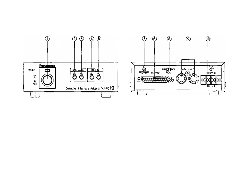
MAJOR OPERATING CONTROLS AND THEIR FUNCTIONS
1. Power ON/OFF Button (POWER ON/OFF)
Note:
The DC power is supplied all the time from
external DC power supply unit even if this
power button is turned off.. Disconnect the
DC power when this unit is not in use for a long
period.
2. System Data Receiving Indicator (SYS DATA RX)
This indicator blinks irregularly for both PC-mode
and Extension-mode while this unit receives the
system data.
Note:
When the system data error occurs, this LED
blinks in 0.5 sec, interval. See page 18 for
details.
- 3 -
Page 6

3. System Data Transmitting Indicator
(SYS DATA TX)
This indicator blinks irregularly for both PC-mode
and Extension-mode while this unit sends the
system data out.
Note:
When the system data error occurs, this LED
blinks in 0.5 sec. interval. See page 18 for
details.
4. RS-232C Receiving Indicator (RS-232 RX)
This indicator blinks irregularly for both PC-mode
and Extension-mode while this unit receives
RS-232C signal from another unit such as Modem
or computer.
Note:
When the system data error occurs, this LED
blinks in 0,5 sec, interval. See page 10 for
details.
Note:
When the system data error occurs, this LED
blinks in 0,5 sec, interval or the error is
indicated on the monitor TV, See page 10 for
details,
6. RS-232C Connector (RS-232C)
Connect this connector with Modem unit, computer
and so on.
Pin configuration
1. GND (Frame ground)
2. SD (TXD)
3. RD (RXD)
4. RS(RTS)
5. CS (CTS)
6. DR (DSR)
7. SG (Signal ground)
20. ER(DTR)
Other pins are not used.
5. RS-232C Transmitting Indicator (RS-232 TX)
This indicator blinks irregularly for both PC-mode
and Extension-mode while this unit transmits
RS-232C signal to another unit such as Modem
or computer.
7. Controller Number Selection Switch
. (CONTROLLER UNIT NO.)
This switch is used to identify the Controller
Unit Number in the system. Up to five(5)
WV-CU300/WJ-PC10 can be installed in the
system.
-4-
Page 7

7-1. PC-mode
1. The numbers other than 1-5 on this switch are
not used.
2. Do not duplicate numbers with other
WV-CU300/WJ-PC10.
7-2. Extension-mode
1, Set this switch to number 0 for every WJ-PCi 0.
8. Data Clock Switch (DATA CLOCK SND/RCV)
When the data clock is supplied to this Data
Input/Output Connector(9), turn this switch to the
RCV position. And when the data clock is sent out
from this connector, turn this switch to the SND
position.
Note:
When the system is separated in some sites
connecting with the modem units and so on,
the SND-RCV connection should be made in
each site. In each site, only one unit should be
set as the SND unit and the other units should
be set as the RCV unit.
9. Data Input/Output Connector (DATA IN/OUT 1 /2)
These connectors send out or accept the system
data to/from other system components in System
300. Also the data clock signal is either sent out or
received through these connectors.
10. 12VDC Input Terminals (DC 12V IN)
Supply 12VDC power to this terminals.
Caution:
Use class 2 power supply only.
- 5 -
Page 8
CABLE CONNECTION
1. RS-232C cable
Use RS-232C standard cable (straight connection)
of up to 49ft (15m) to connect between WJ-PCIO
and other unit such as Modem, computer and so on.
When the cable is to be made locally, refer to the
Pin configuration of RS-232C Connector on page 4,
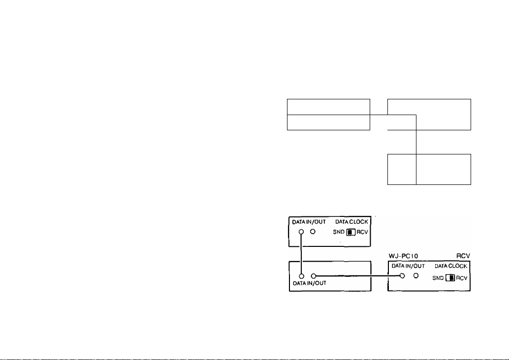
2. System data bus connection
2-1. Cable connection
The two BNC connectors for DATA IN/OUT on
the WJ-MP404, WJ-SQ508 and WV-CU30D are
internally connected and are identical. The System
data bus connection is looped through all units
with the first and last units being automatically
terminated with 75 ohms and all other units being
Hi-Z loop through.
2-2. Data Clock Switch selection
Set the Data Clock Switch on the first unit
connected to the System data bus to the "SND"
so that this unit is the Data Clock supplier. Set the
Data Clock Switch on all other units to the ’RCV”
position.
Data are transmitted and received to and from each
unit connected to the System data bus, in addition
to the Data Clock, through the single coaxial cable.
WV-CU300
DATA IN/O UT DA TA CL OC K
DATA IN/O UT
RCV
^NU | BIHC V
WJ-SQ508
SND
DATA CLO CK
J SN D in RC V
O (
DATAIN/C
JUT
WJ-PCiO
WJ-MP404
SND
WJ-SQ50e
- 6 -
Page 9

SETTING UP OF THE UNIT
Remove four screws fixing the top cover and remove top
cover. There are switches and connectors on the board
as shown below. Set up unit to meet your system.
<Rear Panel Side>
^ 7 -
Page 10

1. SW3 ; Selection of the baud rate of RS-232C signal,
Turn on one of 6 switches.
No.1
1200 bps
No.2 2400 bps
No.3
No.4
4800 bps
9600 bps (Factory set up)
No.5 19200 bps
No.6 38400 bps
SW4 : Selection of the function.
The factory preset switch position is OFF for all
switches.
Select ON or OFF position according to your system.
2-1. Operation mode : PC-mode
SW No. Function
Parity bit
No.1
No.2 Parity mode
Stop bit ON:2bit
No-3
No,4
Data bit
No.5 Alarm selection ON:stop
Main/Sub selection Should be OFF position
No.6
DTE/DCE selection
No.7
No.0 Operation mode Should be
Switch position
ON:None OFF:Yes
ON:EVEN OFFODD
OFF:1 bit
ON:8bit OFF;7bit
OFF:release
ON:DTE
OFFiDCE
OFF position
Note:
When the Alarm switch (No.5) is turned on,
the alarm signal to the RS-232C line can
be stopped. However, the alarm signal
can be confirmed by operating computer via
WJ-PC10.
2-2. Operation mode : Extension-mode
Function
Parity bit
Parity mode
Stop bit
Data bit
Xon/Xoif control
Main/Sub selection
DTE/DCE selection
Operation mode
Switch position
Should be OFF position
Should be OFF position
Should be OFF position
Should be OFF position
Should be OFF position
ON:Sub OFF:Main
ON:DTE OFF:DCE
Should be ON position
Note on Extension-mode:The Modem units should
be set as follows.
Parity
Stop bit
Data bit
Xon/Xotf
None
1 bit
8 bits
Not used
- 8
Page 11

Main/Sub selection on SW4 {No.6) in the Extension
mode.
The WJ-PC10 located in the control site should be
set to Main (OFF) position and the WJ-PC10 located
in the camera site should be set to the Sub (ON)
position as shown.
Sub
■ Camera site
CN10/CN11 ; Selection of RS-232C cable
The Straight RS-232C Cable should be used with
WJ-PC10.
1. When WJ-PC10 is used as a DCE mode,
connect the cable on the board to the CN10
(STR).
2. When WJ-PC10 is used as a DTE mode,
connect the cable on the board to the CN11
(CROSS).
- 9 -
Main
L
■ Control site ■
J
Page 12

GENERAL CONDITION FOR INSTALLATION OF WJ-PC10
1. tn the Extension-mode a pair ol WJ-PC10 which are
designated for the Main and Sub is allowed to install
in one system data bus.
2. In the Extension-mode, the WJ-PCiO which are
designated for either Main's or Sub's are allowed to
connect in different site at one site only.
Camera site ■
However, another pair of WJ-PC10 can not be
installed in the same system data bus as shown.
However, both Main's and Sub’s can not be
connected at the same time on both sites.
-Control site-
-10-
Page 13

L
3. In the Extension-mode, the possible numbef of
WV-CU300 will be fixed according to the baud rate
of RS-232C.
Baud rate
1200 bps
2400 bps
4800 bps
9600 bps
19200 bps
38400 bps
Number of WV-CU300
None
1 pc.
Less than 2pcs.
Less than 4pcs.
Less than 5pcs,
Less than 5pcs.
■Camera site ■
-11-
J
^-----------“Control site^
---------------
^
Page 14

The maximum time delay between the Main
WJ-PC10 and Sub WJ-PC10 should be less than
O.lsec. If the time delay is more than O.lsec, the
WJ-SQ508 on the Sub WJ-PC10 wilt not operate
correctly.
Sub
Time delay less than 0.1 sec
Main
SYSTEM APPLICATION
Important:
1. Refer to the Operating Instructions of the System
300 products for the connection and setting up of
the system.
2. When the Modem is connected with the telephone
line, the Modem should be set to the "exclusive
line mode" due to WJ-PC10 does not have dialing
function,
3. The recommended baud rate of the RS-232C signal
is more than 9600 bps if quick response is required
such as the pan/tilt or focus/zoom of the lens
operatioa
1. PC-mode system
In this application, the System 300 can be remotely
controlled or operated by the computer through
WJ-PC10. The another system may connect with
the computer,
important:
The communication software should be
necessary to operate your system. Please
contact with your dealer or system installer.
- 12 -
Page 15

PC MODE SYSTEM
- 13 -
Page 16

2. Extension-mode 1 system
In this application, the camera sites and the control
site are connected with one video transmitting
line. This application is recommended when every
camera site is located closely.
Note:
The setting up of the Data Clock Switch
(SND/RCV) should be made for the camera site
and control site individually.
- Camera sites
- 14
Page 17

optical fiber/
mi ero* wave
■ Contro) site
- 15 -
Page 18

3. Extension-mode 2 system
In this application, the camera sites and control site
are connected with some video transmitting lines.
This application is recommended when the 4 video
signals are reuired simultaneously using WJ-450
and so on.
Note:
The setting up of the Data Clock Switch
(SND/RCV) should be made for the camera
sites and control site individually.
■ Camera sites ■
- 16 -
Page 19

Video
Monitor TV
- 17 -
Page 20

SYSTEM ERROR TABLE
LED indication Cause
SYS DATA RX No data sync
Duplicated data sync
SYS DATA TX
RS-232 RX 75i7 termination error
RS-232 TX WJ-MP404 site error in PC-mode
Wrong Controller Unit No, • Controller Unit No. is set either 0, 6, 7, 8 or
Duplicated Controller Unit No.
Trouble points
• Data Clock Switch on all units are set to
RCV position,
# Broken system data line with ’’RCV"
WJ-PCIO.
• Duplicated "SND" position of WJ-PCiO with
other units.
9 in PC-mode.
• Controller Unit No. is set other than 0 in
Extension-mode.
• Controller Unit No, duplicated with
WJ-PCiO in PC-mode.
• Broken or non-termination of system data
line with"SND" WJ-PCiO.
• Duplicated "SND’' position of WJ-PCiO with
WJ-MP404.
• Duplicated "Unit No." of system components.
• Broken or non-termination of system data
line.
- 18 -
Page 21

1. PC-mode
Open Open
Trouble point
(1) Broken
(2) Broken
(3) Non-termination
(RCV)
Error indication LED on
WJ-PC10
SYS DATA RX
SYS DATA RX
RS-232 TX
Trouble point
(1) Broken RS-232 RX
(2) Broken RS-232 RX
(3) Non-termination RS-232 RX
- 19 -
(SND)
Error indication LED on
WJ-PCIO
Page 22

2. Example in Extension-mode
Broken No.1
WJ-PC10
|2)
Monitor TV
(RCV) (3)-1
WJ-MP404
(SND)
Broken
WJ-SQ508
(1)
n
Trouble points
No.1 WJ-PC10
(1) Broken SYS DATA RX
{2) Broken
{3)-1 Broken
(3)-2 Broken
(3)-3 Broken
(4) Broken
• Refer to operating instructions of WV-CU300 for CU ERROR: A1.
SYS DATA RX
No error indication available.
LED on RS-232 RX does not light
when no receiving data.
—
Error indication
No.2 WJ-PC10 Monitor TV
— —
— —
RS-232 RX CU ERROR: A1
- 20 -
Broken Broken
Modem —*--4 Modem
(3)-2
WV-CU300
(BCV)
—
No.2
WJ-PC10
(3)-3
RS-232C
(SND)
Page 23

SPECIFICATIONS
Power source:
Input/output:
Controls:
Ambient operating temperature:
Ambient operating humidity:
Dimensions:
Weight:
Weight and dimensions shown are approximate.
Specifications are subject to change without notice.
12VDC, 0.18A
Data In/Out; 1Vp-p/75ohms x2 (BNC)
RS-232C; 25pin D-sub
Controller Number Selection Switch
Data Clock Switch
14‘^F - 122®F(-10°C - +50^0
Les than 95*/.
5-7/16"{W) X 1-3/4"{H) X 7-5/1 6“(D)
[138(W) X 44(H) X 185(D)mm]
1,8 lbs (0.8 kg)
- 21 -
Page 24

Panasonic
Broadcast & Television Systems Company
Division of Matsushita Electric Corporation of America
CLOSED CIRCUIT VIDEO EQUIPMENT DIVISION
Executiv* OWc«: One Panasonw Way, Secaucus, New Jersey 07094
Regional Otflces;
Northeast: 43 Hartz Way. Sacaucus, NJ 07094 (201) 348-7303
Southeast: 1854 Shackleford Court, Suite 115, Norcross, CA 30003 (404) 717-6835
Midwest; 1707 North Randall Road, Elgin, IL 60123 (706) 468-5200
Southwest: 4500 Amon Carter Btvd., Ft, Worth, TX 76155 (617) 685-1117
Western: 6550 Katella Ave„ Cypress, CA 90630 (714) 373-7265
_
N0193-0 YWV8QA2962AN
Printed in Japan
(N) 15
 Loading...