

Page 1
-1-
Before attempting to connect or install this product,
please read these instructions carefully and save this manual for future use.
Extend Card (Loop Through)
1
2
3
4
5
6
7
8
IN/OUT
IN/OUT
THRU
q
w
Model No. WJ-PB85Y08
■Preface
The WJ-PB85Y08 Loop Through Board is an optional board used to exchange the BNC video
input/output for the D-Sub video output/input in order to expand the capabilities of the System
850 Matrix Switcher.
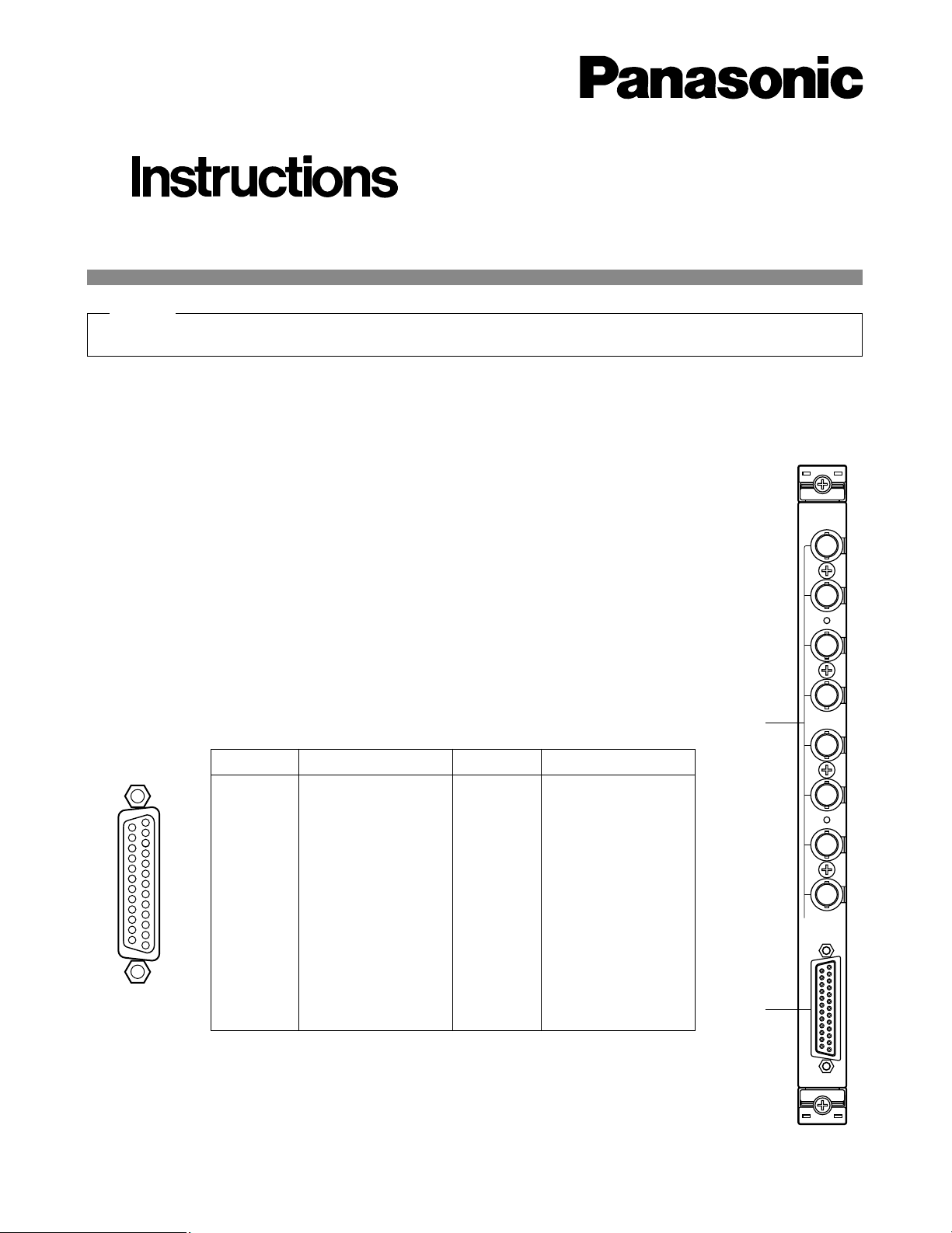
■Appearance
q Through I/O Connectors (IN / OUT, 1 - 8)
These connectors accept the composite video output from the associated video equipment,
or provide the looped through video outputs connected to the Through I/O Port.
w Through I/O Port (IN / OUT)
This port accepts the composite video output from the associated video equipment, or provide the looped through video outputs connected to the Through I/O Connectors.
17
16
15
14
5
4
3
2
1
20
19
18
8
6
23
22
21
11
10
9
7
25
24
13
12
Pin No. Designation
25
24
23
22
21
20
19
18
17
16
15
14
VIDEO 1
VIDEO 2
VIDEO 3
VIDEO 4
VIDEO 5
VIDEO 6
VIDEO 7
VIDEO 8
Not used
Not used
Not used
Not used
Pin No. Designation
13
12
11
10
9
8
7
6
5
4
3
2
1
Ground
Ground
Ground
Ground
Ground
Ground
Ground
Ground
Ground
Ground
Ground
Ground
Ground
Hold this board only by its edges. Otherwise components on the board may be damaged by static electricity.
Caution
Page 2
-2-
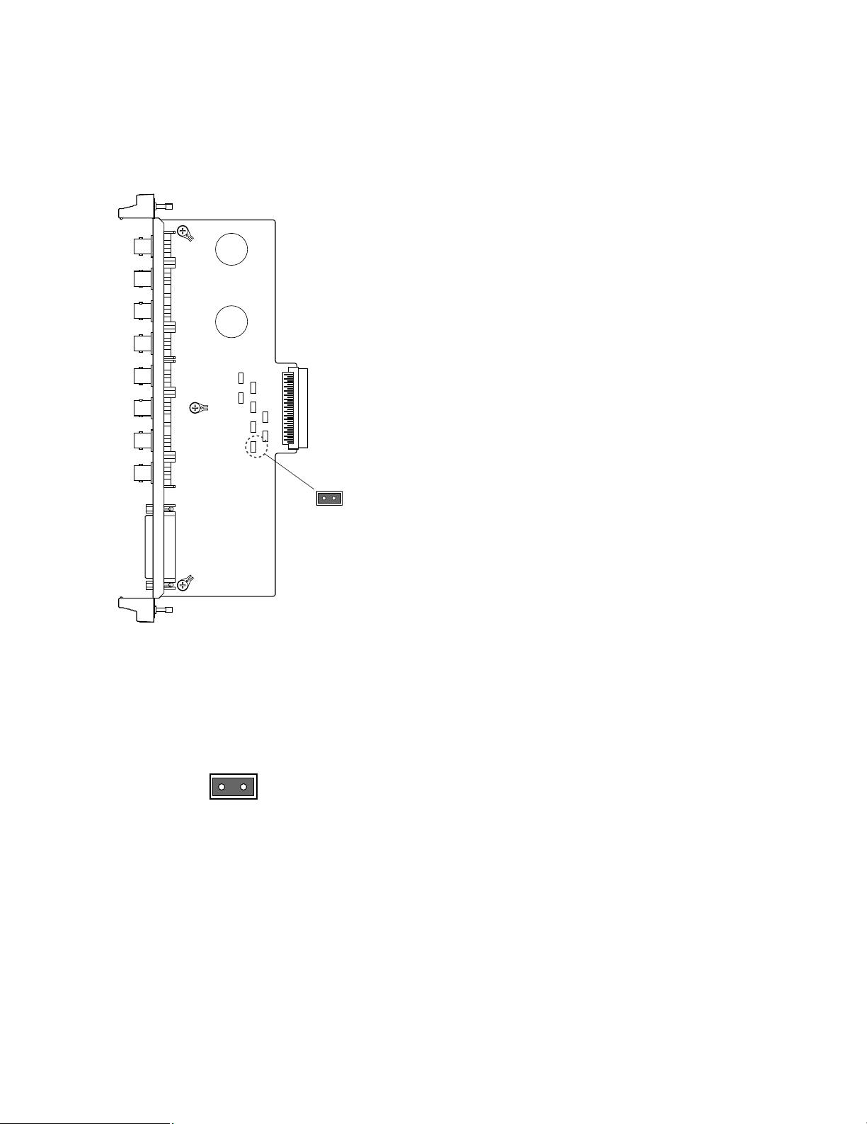
■Board Setting
Before installing this board, the following setting should
be made by qualified service personnel or system
installers.
CN801
1
2
CN601CN401CN201
CN701CN501
CN301CN101
CN801
1. Confirm that jumper connectors (CN101, CN201,
CN301, CN401, CN501, CN601, CN701, and
CN801) on the board are positioned as shown
below.
CN101
12
Page 3

-3-
■Installation
The following installation should be made by qualified
service personnel or system installers.
● Installing Additional Extension
Boards
1. Remove the screws from the rear panel(s) of the
WJ-SX850 Matrix Switcher Card Cage.
2. Remove the rear panel(s).
3. Place the Boards into the specified positions in the
rear of the Cage by sliding them along the board
guides as shown below.
4. Make sure to push in the Boards until they are seated firmly.
5. Secure the rear board by tightening the two screws
on the board.
6. Close open spaces on the rear of the Cage with the
supplied rear panel(s).
Board
Tighten screws
Tighten screws
Rear
panel
Rear
panel
Tighten screws
Page 4

■Specifications
Video Input/Output (1 - 8): 1.0 V[p-p]/75Ω composite video signal
BNC connector (x8)
Video Input/Output: 1.0 V[p-p]/75Ω composite video signal
25-pin D-sub connector (x1)
Dimensions: 117.5(W) x 265(H) x 20(D) mm
4-5/8”(W) x 10-7/16”(H) x 13/16”(D)
Weight: 0.2 kg (0.4 lbs)
Weight and dimensions indicated are approximate.
Specifications are subject to change without notice.
NM1099-0 YWV8QA5227AN Printed in Japan
N 19
© Matsushita Communication Industrial Co., Ltd. 1999
Panasonic Canada Inc.
5770 Ambler Drive, Mississauga,
Ontario, L4W 2T3 Canada (905)624-5010
Panasonic Sales Company
Division of Matsushita Electric of Puerto Rico Inc.
Ave. 65 de Infanteria. Km. 9.5
San Gabriel Industrial Park, Carolina,
Puerto Rico 00985 (809)750-4300
Panasonic Security and Digital Imaging Company
A Division of Matsushita Electric Corporation of America
Executive Office: One Panasonic Way 3E-7, Secaucus, New Jersey 07094
Regional Offices:
Northeast: One Panasonic Way, Secaucus, NJ 07094 (201) 348-7303
Southern: 1225 Northbrook Parkway, Suite 1-160, Suwanee, GA 30024 (770) 338-6838
Midwest: 1707 North Randall Road, Elgin, IL 60123 (847) 468-5211
Western: 6550 Katella Ave., Cypress, CA 90630 (714) 373-7840
 Loading...