

Page 1
-1-
Before attempting to connect or install this product,
please read these instructions carefully and save this manual for future use.
Extend Card (Camera in)
1
2
3
4
5
6
7
8
CAMERA IN
VIDEO OUT
CAMERA
q
w
Model No. WJ-PB85X08
■Preface
The WJ-PB85X08 Camera Input Board is an optional board for expanding the camera input
capability of the System 850 Matrix Switcher.
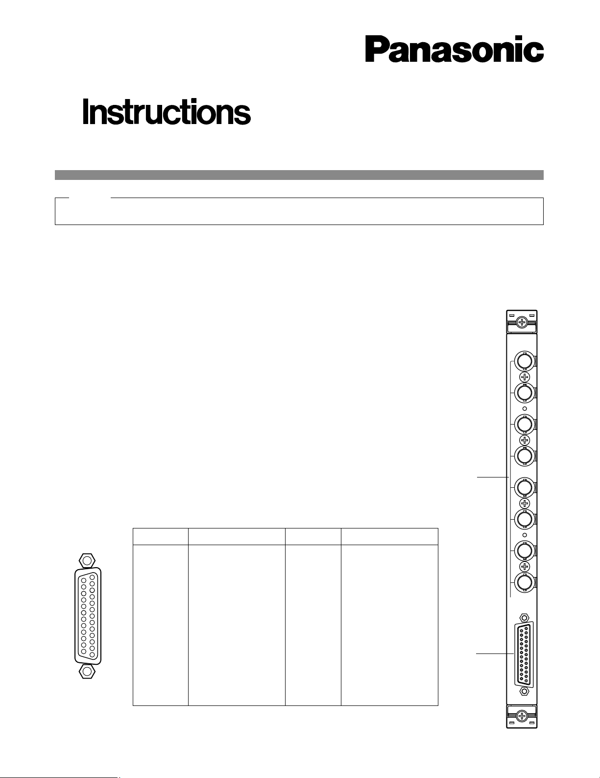
■Appearance
q Camera Input Connector (CAMERA IN, 1 - 8)
These connectors accept either a color or B/W composite video signal from a camera.
In addition, the VD2 signal for synchronizing the vertical timing of the cameras, and data to
control camera site devices are multiplexed through this connector.
w Video Output Port (VIDEO OUT)
The video signal connected to the Camera Input Connector (CAMERA IN) is present at this
port.
The camera control data multiplexed on the video signal is not available at this port. When
the power of the Matrix Switcher Card cage is turned off, no signal is present at this port.
Connect between this output port and the VIDEO IN Port on the WJ-PB85C16 Cross Point
Input Board of the Cross Point Cage (MXSW) for switching camera input.
17
16
15
14
5
4
3
2
1
20
19
18
8
6
23
22
21
11
10
9
7
25
24
13
12
Pin No. Designation
25
24
23
22
21
20
19
18
17
16
15
14
CAMERA 1
CAMERA 2
CAMERA 3
CAMERA 4
CAMERA 5
CAMERA 6
CAMERA 7
CAMERA 8
Not used
Not used
Not used
Not used
Pin No. Designation
13
12
11
10
9
8
7
6
5
4
3
2
1
Ground
Ground
Ground
Ground
Ground
Ground
Ground
Ground
Ground
Ground
Ground
Ground
Ground
Hold this board only by its edges. Otherwise components on the board may be damaged by static electricity.
Caution
Page 2
-2-
SW1
SW1
SW5SW4SW2
CN5
CN4
CANERA CNT
CN 101
CN 103
CN 102
CN 201
CN 203
CN 202
CN 301
CN 303
CN 302
CN 401
CN 403
CN 402
CN 501
CN 503
CN 502
CN 601
CN 603
CN 602
CN 701
CN 703
CN 702
CN 801
CN 803
CN 802
OFF
1234
0
1
2
3
4
5
6
7
8
9
A
B
C
D
E
F
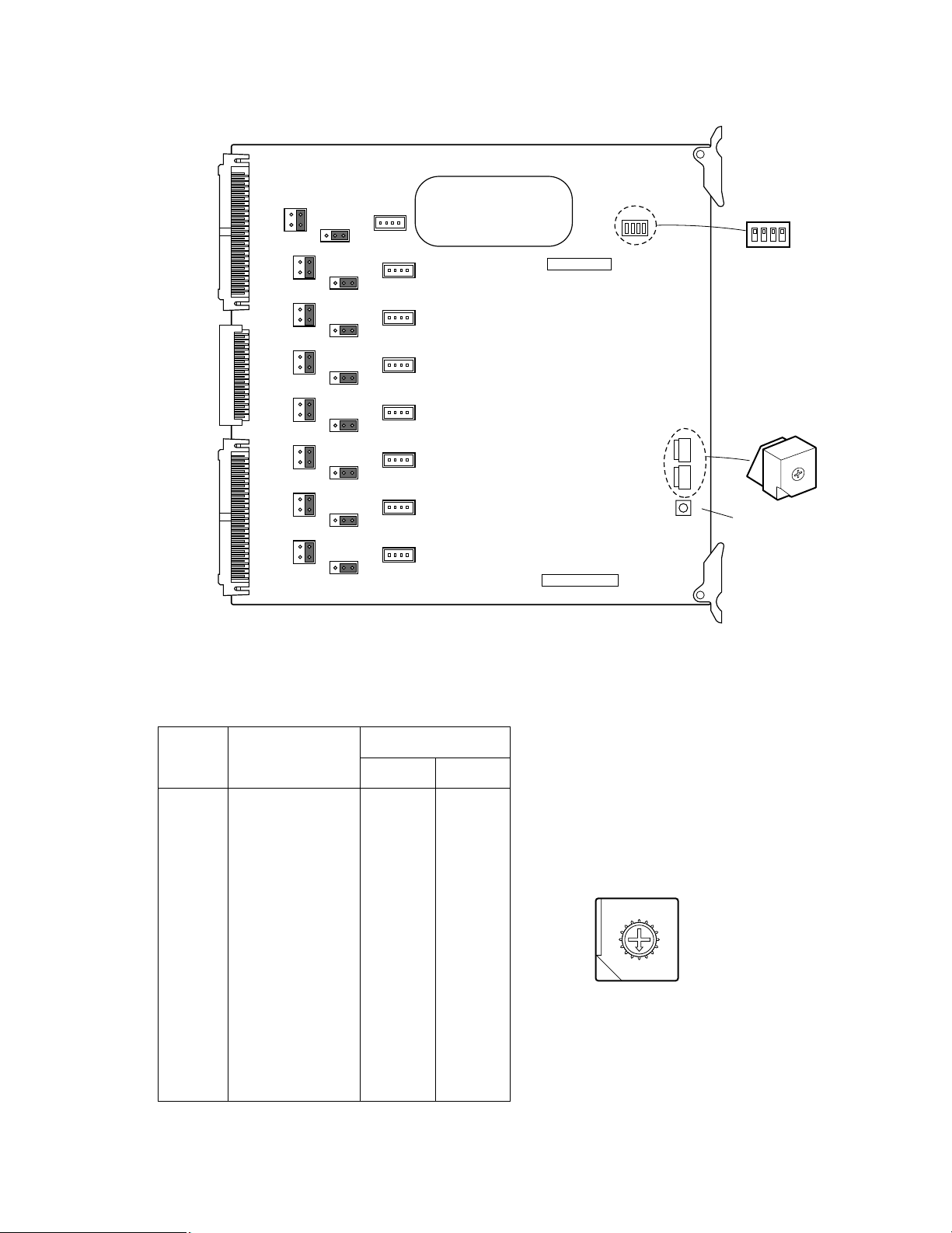
Reset Switch
1. Set switches (SW4 and SW5) on the board to designate the camera input board number as shown in the following table.
The factory default setting is Board Number 1 (00)
Board
No.
Camera Input
SW Positions
SW5 SW4
1
2
3
4
5
6
7
8
9
10
11
12
13
14
15
16
0
0
0
0
0
0
0
0
0
0
0
0
0
0
0
0
0
1
2
3
4
5
6
7
8
9
A
B
C
D
E
F
1 - 8
9 - 16
17 - 24
25 - 32
33 - 40
41 - 48
49 - 56
57 - 64
65 - 72
73 - 80
81 - 88
89 - 96
97 - 104
105 - 112
113 - 120
121 - 128
8
9
A
B
C
D
E
F
0
1
2
3
4
5
6
7
■Board Setting
Before installing this board, the following settings should be made by qualified service personnel or system installers.
Page 3

DIP
-3-
2. Confirm that switches (SW1) on the board are set to
the OFF position as shown below.
SW1
OFF
1234
3. Position jumper connectors (CN101, CN201,
CN301, CN401, CN501, CN601, CN701, and
CN801) on the board as shown below.
The factory default setting is positions 3 and 4
(Multiplexed Camera).
4. If the Character Board is installed on the Camera
Input Board, position jumper connectors (CN103,
CN203, CN303, CN403, CN503, CN603, CN703,
and CN803) on the board as shown below.
The factory default setting is positions 1 and 2.
CN101
13
24
CN101
Multiplexed Camera
Default Setting
Others
13
24
CN103
31
CN103
Default Setting Installed
Character Board
13
■Installation
The following installation should be made by qualified
service personnel or system installers.
● Installing a Character Board
If the WJ-PB85D01 Character Board is installed on the
WJ-PB85X08 Camera Input Board, follow the procedure
shown below.
1. Insert the connectors of the Character board into the
specified connectors (CN102, CN202, CN302,
CN402, CN502, CN602, CN702, and CN802) on the
Camera Input board.
2. Place the Character board on the Camera Input
board and plug in the boards.
ON
1
Character display
without camera input
2 No retry mode
3 Reserved
4 Reserved (P)
OFF
No display
without camera input
3 retries mode
Reserved
Reserved (N)
Page 4

-4-
● Installing Additional Extension
Boards
1. Remove the screws from the rear panel(s) of the
WJ-SX850 Matrix Switcher Card Cage.
2. Remove the rear panel(s).
3. Remove the front panel of the cage by removing the
two screws on the panel shown below.
3. Fix both boards with the two supplied screws
(M3x6) as shown below.
Page 5

-5-
4. Place the Boards into the specified positions in the
front or rear of the Cage by sliding them along the
board guides as shown below.
5. Make sure to push in the Boards until they are seated firmly.
6. Secure the rear board by tightening the two screws
on the board.
7. Close open spaces on the rear of the Cage with the
supplied rear panel(s).
8. Close the front of the cage by fixing the front panel.
Board
Tighten screws
Tighten screws
Rear
panel
Rear
panel
Tighten screws
Page 6

-6-
■Specifications
Camera Input (1 - 8): 1.0 V[p-p]/75Ω composite video signal
0.5 V[p-p]/75Ω data signal and 2.5 V[p-p]/ 75Ω vertical timing pulse multiplexed.
Video Output: 1.0 V[p-p]/75Ω composite video signal
25-pin D-sub connector
Functions: Cable compensation: S, M, L (Short, Middle, Long)
Vertical Drive Pulse (VD2) Output: On / Off
Control Data Output: On / Off
Dimensions: Front Board; 255(W) x 250(H) x 12(D) mm
10-1/16”(W) x 9-13/16”(H) x 1/2”(D)
Rear Board; 117.5(W) x 265(H) x 20(D) mm
4-5/8”(W) x 10-7/16”(H) x 13/16”(D)
Weight: 0.6 kg (1.3 lbs)
Weight and dimensions indicated are approximate.
Specifications are subject to change without notice.
Page 7

NM1099-0 YWV8QA5054AN Printed in Japan
N 19
© Matsushita Communication Industrial Co., Ltd. 1999
Panasonic Canada Inc.
5770 Ambler Drive, Mississauga,
Ontario, L4W 2T3 Canada (905)624-5010
Panasonic Sales Company
Division of Matsushita Electric of Puerto Rico Inc.
Ave. 65 de Infanteria. Km. 9.5
San Gabriel Industrial Park, Carolina,
Puerto Rico 00985 (809)750-4300
Panasonic Security and Digital Imaging Company
A Division of Matsushita Electric Corporation of America
Executive Office: One Panasonic Way 3E-7, Secaucus, New Jersey 07094
Regional Offices:
Northeast: One Panasonic Way, Secaucus, NJ 07094 (201) 348-7303
Southern: 1225 Northbrook Parkway, Suite 1-160, Suwanee, GA 30024 (770) 338-6838
Midwest: 1707 North Randall Road, Elgin, IL 60123 (847) 468-5211
Western: 6550 Katella Ave., Cypress, CA 90630 (714) 373-7840
 Loading...