

Page 1
-1-
■Preface
The WJ-PB85R08 RS485 Data Board is an optional board for exchange of control data between
the Camera Control Cage (MXCONT) and the camera site.
■Appearance
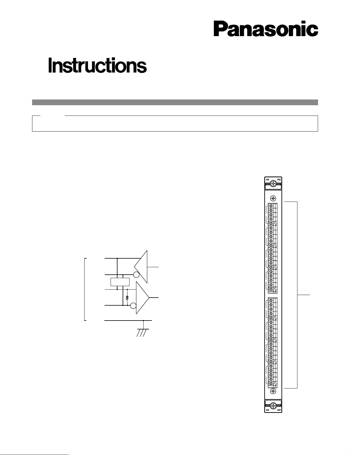
q Data Connectors (TA/TB/RA/RB/G 1 - 8)
These connectors are used to exchange control data between the camera site equipment.
For connection, use a data grade shielded 4-wire twisted pair cable suitable for RS-485 communication.
q
RS485
A
T
B
A
R
B
G
A
T
B
A
R
B
G
A
T
B
A
R
B
G
A
T
B
A
R
B
G
1
2
3
4
A
T
B
A
R
B
G
A
T
B
A
R
B
G
A
T
B
A
R
B
G
A
T
B
A
R
B
G
5
6
7
8
Before attempting to connect or install this product,
please read these instructions carefully and save this manual for future use.
Extend Card (RS485 Data)
Model No. WJ-PB85R08
TXD
TB
RA (+)
RB
GND
RXDRT
TA (+)
S W
1
RT: Termination Resistor
SW: Selection Switch, Full Duplex/ Half Duplex
GND: Ground; Connected to each channel and
common ground.
Hold this board only by its edges. Otherwise components on the board may be damaged by static electricity.
Caution
Page 2
-2-
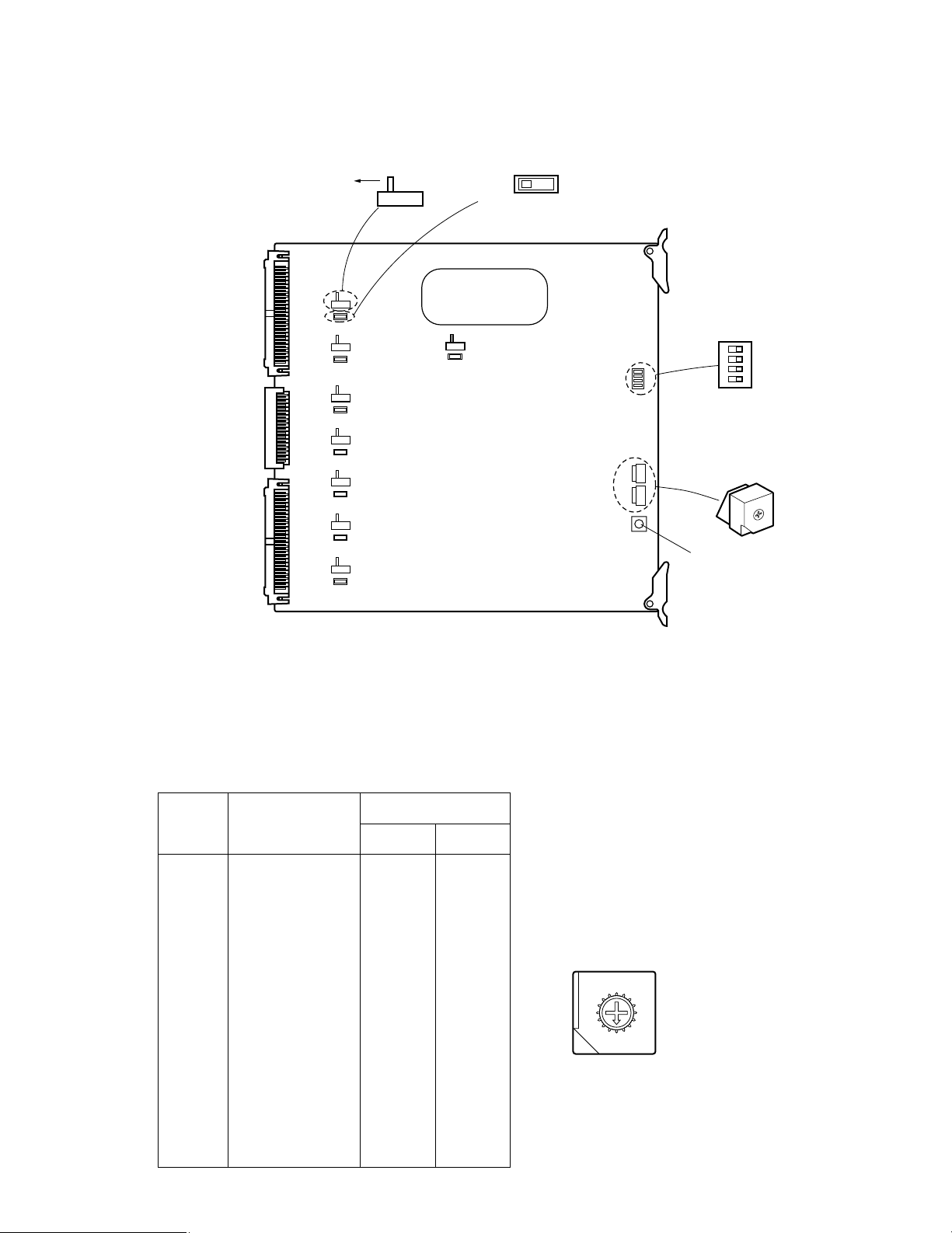
■Board Setting
Before installing this board, the following settings should be made by qualified service personnel or system installers.
1234
OFF
SW3
SW2SW1SW4
RS-485 DATA BOARD
0
1
2
3
4
5
6
7
8
9
A
B
C
D
E
F
SW102
SW101
SW302
SW301
SW202
SW201
SW402
SW401
SW502
SW501
SW602
SW601
SW702
SW701
SW802
SW801
4LINE 2LINE
TERM
ON
TERM
OFF
Reset Switch
Board
No.
Data I/O
SW Positions
SW2 SW1
1
2
3
4
5
6
7
8
9
10
11
12
13
14
15
16
0
0
0
0
0
0
0
0
0
0
0
0
0
0
0
0
0
1
2
3
4
5
6
7
8
9
A
B
C
D
E
F
1 - 8
9 - 16
17 - 24
25 - 32
33 - 40
41 - 48
49 - 56
57 - 64
65 - 72
73 - 80
81 - 88
89 - 96
97 - 104
105 - 112
113 - 120
121 - 128
1. Set switches (SW1 and SW2) on the board to designate the RS-485 Data board number as shown in the following table.
The factory default setting is Board Number 1 (00).
8
9
A
B
C
D
E
F
0
1
2
3
4
5
6
7
Page 3

-3-
2. Set switches (SW101, SW201, SW301, SW401,
SW501, SW601, SW701, and SW801) on the board
to choose either data termination ON or OFF as
shown below.
The factory default settings are TERM ON.
TERM
ON
TERM
OFF
■Installation
The following installation should be made by qualified
service personnel or system installers.
● Installing Additional Extension
Boards
1. Remove the screws from the rear panel(s) of the
WJ-SX850 Matrix Switcher Card Cage.
2. Remove the rear panel(s).
3. Remove the front panel of the cage by removing the
two screws on the panel shown below.
3. Set switches (SW102, SW202, SW302, SW402,
SW502, SW602, SW702, and SW802) on the board
to choose either Full Duplex (4 LINE) or Half Duplex
(2 LINE) communication lines as shown below.
The factory default settings are Full Duplex (4 LINE).
4LINE 2LINE
4. Confirm that switches (SW3) on the board are set to
the OFF position as shown below.
1234
OFF
DIP ON
1 One way mode
2 No retry mode
3 Reserved
4 Reserved
OFF
Handshake mode
3 retries mode
Reserved
Reserved
Page 4

4. Place the Boards into the specified positions in the
front or rear of the Cage by sliding them along the
board guides as shown below.
5. Make sure to push in the Boards until they are seated firmly.
6. Secure the rear board by tightening the two screws
on the board.
■Specifications
Data Input/Output (1 - 8): RS-485 [5-pin T(A), T(B), R(A), R(B), G] x8
Full Duplex or Half Duplex selectable
Transmission Speed (Baud Rate): 1 200 - 19 200 bps
Dimensions: Front Board; 255(W) x 250(H) x 12(D) mm
10-1/16”(W) x 9-13/16”(H) x 1/2”(D)
Rear Board; 117.5(W) x 265(H) x 20(D) mm
4-5/8”(W) x 10-7/16”(H) x 13/16”(D)
Weight: 0.5 kg (1.1 lbs)
Weight and dimensions indicated are approximate.
Specifications are subject to change without notice.
NM1099-0 YWV8QA5055AN Printed in Japan
N 19
© Matsushita Communication Industrial Co., Ltd. 1999
Panasonic Canada Inc.
5770 Ambler Drive, Mississauga,
Ontario, L4W 2T3 Canada (905)624-5010
Panasonic Sales Company
Division of Matsushita Electric of Puerto Rico Inc.
Ave. 65 de Infanteria. Km. 9.5
San Gabriel Industrial Park, Carolina,
Puerto Rico 00985 (809)750-4300
Panasonic Security and Digital Imaging Company
A Division of Matsushita Electric Corporation of America
Executive Office: One Panasonic Way 3E-7, Secaucus, New Jersey 07094
Regional Offices:
Northeast: One Panasonic Way, Secaucus, NJ 07094 (201) 348-7303
Southern: 1225 Northbrook Parkway, Suite 1-160, Suwanee, GA 30024 (770) 338-6838
Midwest: 1707 North Randall Road, Elgin, IL 60123 (847) 468-5211
Western: 6550 Katella Ave., Cypress, CA 90630 (714) 373-7840
7. Close open spaces on the rear of the Cage with the
supplied rear panel(s).
8. Close the front of the cage by fixing the front panel.
Board
Tighten screws
Tighten screws
Rear
panel
Rear
panel
Tighten screws
 Loading...