

Page 1
-1-
q
w
1
2
VIDEO IN
1
2
VIDEO OUT
OUTPUT
■Preface
The WJ-PB85M16 Cross Point Output Board is an optional board for expanding the cross point output capability of the
System 850 Matrix Switcher.
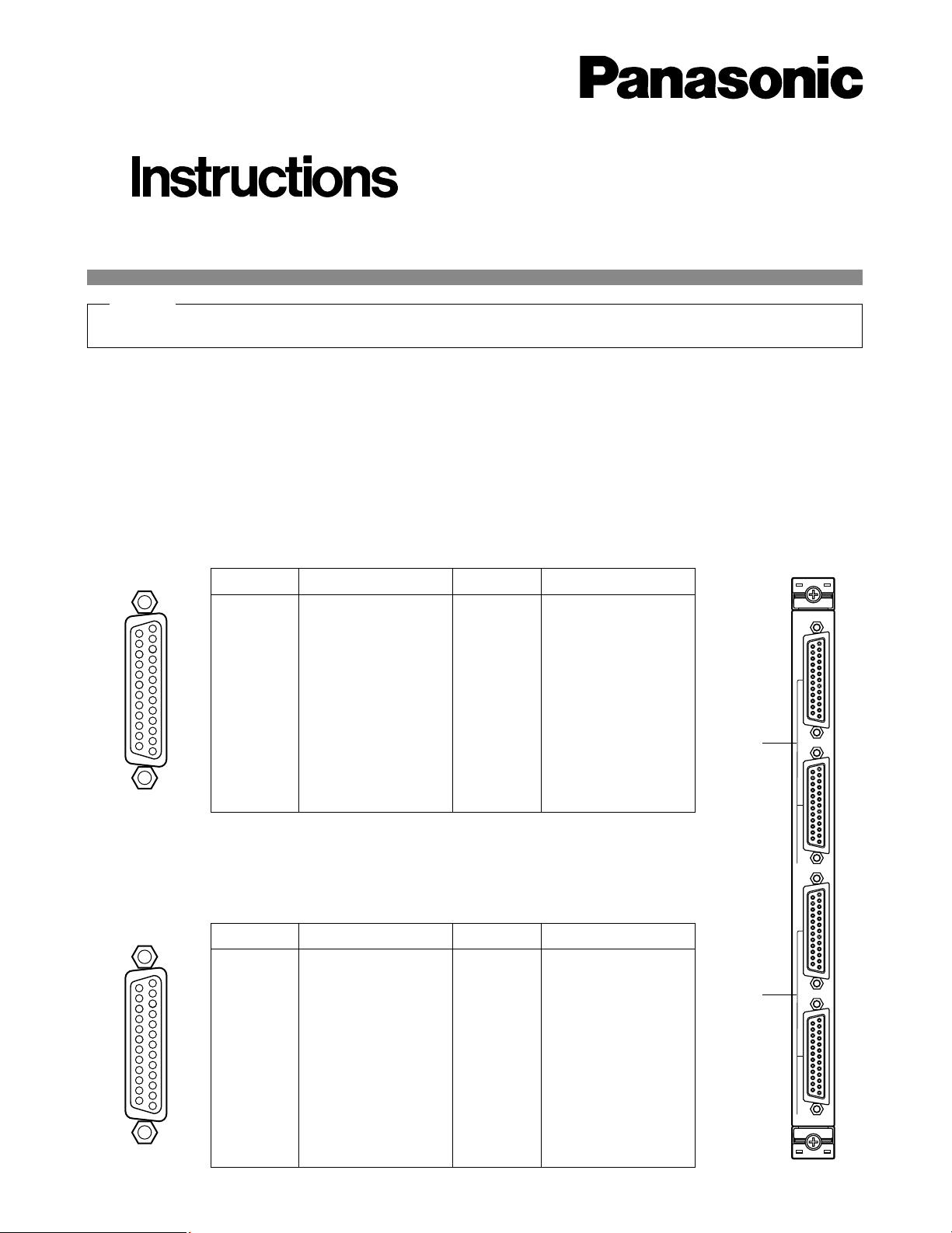
■Appearance
q Video Input Port (VIDEO IN, 1 - 2)
These ports accept the video signal from the VIDEO OUT Port on the WJ-PB85M16 Cross Point Output Board of another
Cross Point Cage (MXSW) for cascade input.
Before attempting to connect or install this product,
please read these instructions carefully and save this manual for future use.
Extend Card (Cross Point out)
Model No. WJ-PB85M16
17
16
15
14
5
4
3
2
1
20
19
18
8
6
23
22
21
11
10
9
7
25
24
13
12
1
VIDEO 1
VIDEO 2
VIDEO 3
VIDEO 4
VIDEO 5
VIDEO 6
VIDEO 7
VIDEO 8
Not Used
Not Used
Not Used
Not Used
Pin No. Designation
25
24
23
22
21
20
19
18
17
16
15
14
Pin No. Designation
13
12
11
10
9
8
7
6
5
4
3
2
1
Ground
Ground
Ground
Ground
Ground
Ground
Ground
Ground
Ground
Ground
Ground
Ground
Ground
17
16
15
14
5
4
3
2
1
20
19
18
8
6
23
22
21
11
10
9
7
25
24
13
12
2
VIDEO 9
VIDEO 10
VIDEO 11
VIDEO 12
VIDEO 13
VIDEO 14
VIDEO 15
VIDEO 16
Not Used
Not Used
Not Used
Not Used
Pin No. Designation
25
24
23
22
21
20
19
18
17
16
15
14
Pin No. Designation
13
12
11
10
9
8
7
6
5
4
3
2
1
Ground
Ground
Ground
Ground
Ground
Ground
Ground
Ground
Ground
Ground
Ground
Ground
Ground
w Video Output Port (VIDEO OUT, 1 - 2)
These ports provide the video signal to the VIDEO IN Port on the WJ-PB85M16 Cross Point
Output Board of another Cross Point Cage (MXSW), or to the VIDEO IN Port on the WJPB85T08 On Screen Display Board of the On Screen Display Cage (MXOSD) for expanding
video output capability.
Hold this board only by its edges. Otherwise components on the board may be damaged by static electricity.
Caution
Page 2
-2-
SW703SW702
0
1
2
3
4
5
6
7
8
9
A
B
C
D
E
F
CN201
CN202
CN203
CN204
CN205
CN206
CN207
CN208
CN209
CN210
CN211
CN212
CN213
CN214
CN215
CN216
CN232
CN225
CN224
CN223
CN217
CN232
CN201
13
2
10
1
9
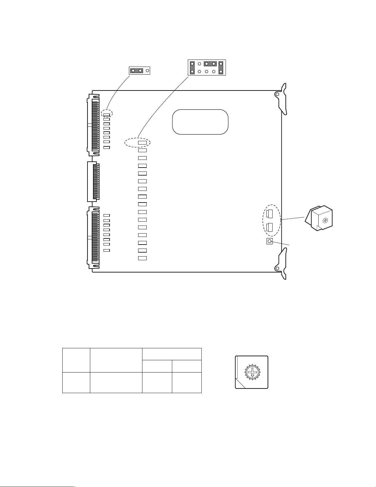
SW1
Reset Switch
Board
No.
VIDEO IN/OUT
SW Positions
SW703 SW702
1
2
0
0
0
1
1 - 16
17 - 32
1. Set switches (SW702 and 703) on the board to designate the Cross Point Output board number as shown in the following table.
The factory default setting is Board Number 1 (00).
8
9
A
B
C
D
E
F
0
1
2
3
4
5
6
7
■Board Setting
Before installing this board, the following settings should be made by qualified service personnel or system installers.
Page 3
-3-
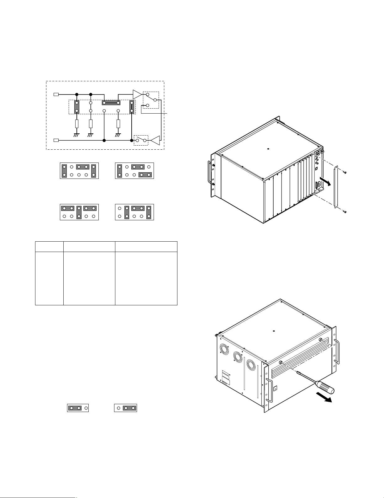
2. Position jumper connectors (CN201, CN202,
CN203, CN204, CN205, CN206, CN207, CN208,
CN209, CN210, CN211, CN212, CN213, CN214,
CN215, CN216) on the board as shown below.
The factory default setting is position MODE A
(Normal).
246 10
13579
150 Ω150 Ω75 Ω
VIDEO IN
VIDEO OUT
S2
S
246810
13579
MODE A
Default Setting
246810
13579
MODE B
246810
13579
MODE C
246810
13579
MODE D
■Installation
The following installation should be made by qualified
service personnel or system installers.
● Installing Additional Extension
Boards
1. Remove the screws from the rear panel(s) of the
WJ-SX850 Matrix Switcher Card Cage.
2. Remove the rear panel(s).
3. Remove the front panel of the cage by removing the
two screws on the panel shown below.
MODE Input Spec. Output Spec.
MODE A
MODE B
MODE C
MODE D
75 Ω Termination
75 Ω Termination
Hi-Z Termination
150 Ω Termination
75 Ω Buffered Output
75 Ω with 150 Ω
Termination Buffered
Output
Wired Loop Through
75 Ω Buffered Output
For detail settings, refer to the appendix on page
5.
3. When two cross point output boards are installed in
a Cross Point Cage (MXSW), position jumper connectors (CN217, CN218, CN219, CN220, CN221,
CN222, CN223, CN224, CN225, CN226, CN227,
CN228, CN229, CN230, CN231, CN232) on the
board to assign outputs as shown below.
The factory default setting is positions 1 and 2.
13
Output 1-16
Default Setting
13
Output 17-32
Page 4

4. Place the Boards into the specified positions in the
front or rear of the Cage by sliding them along the
board guides as shown below.
5. Make sure to push in the Boards until they are seated firmly.
6. Secure the rear board by tightening the two screws
on the board.
Board
Tighten screws
Tighten screws
Rear
panel
Rear
panel
Tighten screws
7. Close open spaces on the rear of the Cage with the
supplied rear panel(s).
8. Close the front of the cage by fixing the front panel.
-4-
Page 5

-5-
■Appendix
● Jumper Connector Positions for Cage Extension
Examples of jumper connector settings are shown below.
246 10
1357
150 Ω150 Ω75 Ω
VIDEO IN
VIDEO OUT
268
13579
150 Ω150 Ω75 Ω
VIDEO IN
VIDEO OUT
246 10
13579
150 Ω150 Ω75 Ω
VIDEO IN
VIDEO OUT
S2
S2
S2
S
S
S
Termination for 75 Ω input and 150 Ω output
Hi-Z input
Termination for 150 Ω input
Cross-point output for 1 channel
Jumper post on the board
Initial-stage cage
• This stage has a configuration that enables it to
accept an extended video input in the form of an
input terminated at 75 Ω. Actually, however, this
external input terminal is invalid.
• When an input of this cage is selected, S of this
cage is turned on and S of other cages is turned off.
• In order to secure 75 Ω for signal send-out from the
initial stage, a 150 Ω termination is provided for the
75Ω impedance dive and another 150 Ω termination
is provided at the final stage.
Middle-stage cage
• When an input of this cage is selected, S of this
cage is turned on and S of other cages is turned off.
• A wired loop-through system is used for the common output video bus of the cage. Therefore, a failure of the power supply to the middle-stage cage
would not cause any problem in the successive
stages.
Note: If the video output is 768 or above, this mid-
dle-stage cage may need further extension.
Final-stage cage: Final-stage
• The selected output of all cross-point inputs
obtained at the final stage is generated from the
VIDEO OUT terminal of this cage and can be
applied to a video monitor.
• S of this cage is turned on at all times. S2 is used for
the changeover between the cross-point input of
this cage and that of other cages.
Page 6

-6-
■Specifications
VIDEO Input (1 - 2): 1.0 V[p-p]/75 Ω composite video signal
8 inputs 25-pin D-sub connector (x2)
Video Output (1 - 2): 1.0 V[p-p]/75 Ω composite video signal
8 outputs 25-pin D-sub connector (x2)
Dimensions: Front Board; 255(W) x 250(H) x 12(D) mm
10-1/16”(W) x 9-13/16”(H) x 1/2”(D)
Rear Board; 117.5(W) x 265(H) x 20(D) mm
4-5/8”(W) x 10-7/16”(H) x 13/16”(D)
Weight: 0.5 kg (1.1 lbs)
Weight and dimensions indicated are approximate.
Specifications are subject to change without notice.
Page 7

Page 8

NM1099-0 YWV8QA5057AN Printed in Japan
N 19
© Matsushita Communication Industrial Co., Ltd. 1999
Panasonic Canada Inc.
5770 Ambler Drive, Mississauga,
Ontario, L4W 2T3 Canada (905)624-5010
Panasonic Sales Company
Division of Matsushita Electric of Puerto Rico Inc.
Ave. 65 de Infanteria. Km. 9.5
San Gabriel Industrial Park, Carolina,
Puerto Rico 00985 (809)750-4300
Panasonic Security and Digital Imaging Company
A Division of Matsushita Electric Corporation of America
Executive Office: One Panasonic Way 3E-7, Secaucus, New Jersey 07094
Regional Offices:
Northeast: One Panasonic Way, Secaucus, NJ 07094 (201) 348-7303
Southern: 1225 Northbrook Parkway, Suite 1-160, Suwanee, GA 30024 (770) 338-6838
Midwest: 1707 North Randall Road, Elgin, IL 60123 (847) 468-5211
Western: 6550 Katella Ave., Cypress, CA 90630 (714) 373-7840
 Loading...