

Page 1
-1-
1-32
ALARM
OUT
q
■Preface
The WJ-PB85L32 Alarm Output Board is an optional board for expanding the capabilities of the
System 850 Matrix Switcher.
A received alarm signal, and a pulse generated in the Digital Output operation by the controller,
are transmitted to the CPU (Central Processing Unit) via Ethernet to enable control of the alarm
contacts on this board.
The board can also output the status of any alarm activated by the camera's motion detector,
alarm acknowledgment and alarm reset.
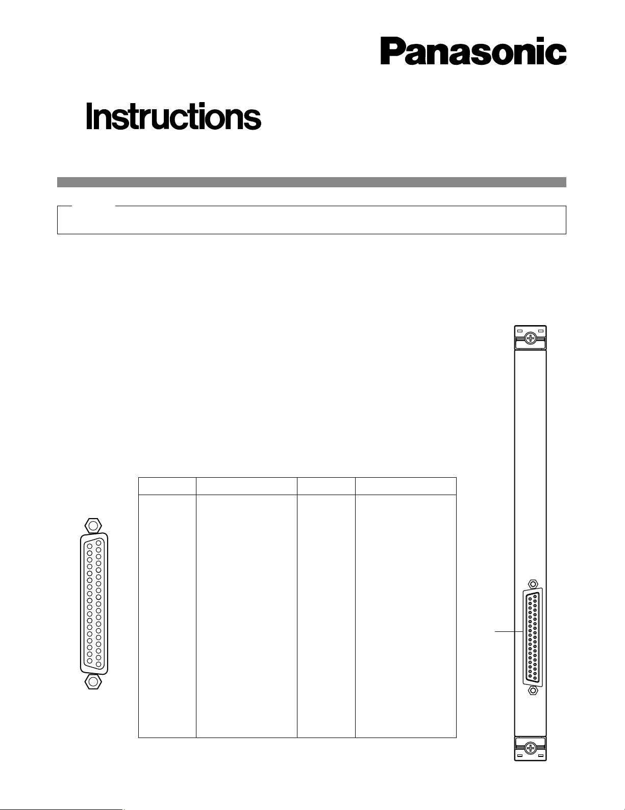
■Appearance
q Alarm Output Port (1 - 32)
This port supplies alarm output to the actuators connected to it through either Normally Open
(N.O) or Normally Closed (N.C) contacts on this board.
Before attempting to connect or install this product,
please read these instructions carefully and save this manual for future use.
Extend Card (Alarm out)
Model No. WJ-PB85L32
23
22
21
20
5
4
3
2
1
26
25
24
8
6
29
28
27
11
10
9
7
32
31
30
14
13
12
33
15
36
35
34
18
37
19
17
16
Ground
Ground
Not used
Not used
Not used
Alarm 32
Alarm 31
Alarm 30
Alarm 29
Alarm 28
Alarm 27
Alarm 26
Alarm 25
Alarm 24
Alarm 23
Alarm 22
Alarm 21
Alarm 20
Pin No. Designation
37
36
35
34
33
32
31
30
29
28
27
26
25
24
23
22
21
20
Pin No. Designation
19
18
17
16
15
14
13
12
11
10
9
8
7
6
5
4
3
2
1
Alarm 19
Alarm 18
Alarm 17
Alarm 16
Alarm 15
Alarm 14
Alarm 13
Alarm 12
Alarm 11
Alarm 10
Alarm 9
Alarm 8
Alarm 7
Alarm 6
Alarm 5
Alarm 4
Alarm 3
Alarm 2
Alarm 1
Hold this board only by its edges. Otherwise components on the board may be damaged by static electricity.
Caution
Page 2
-2-
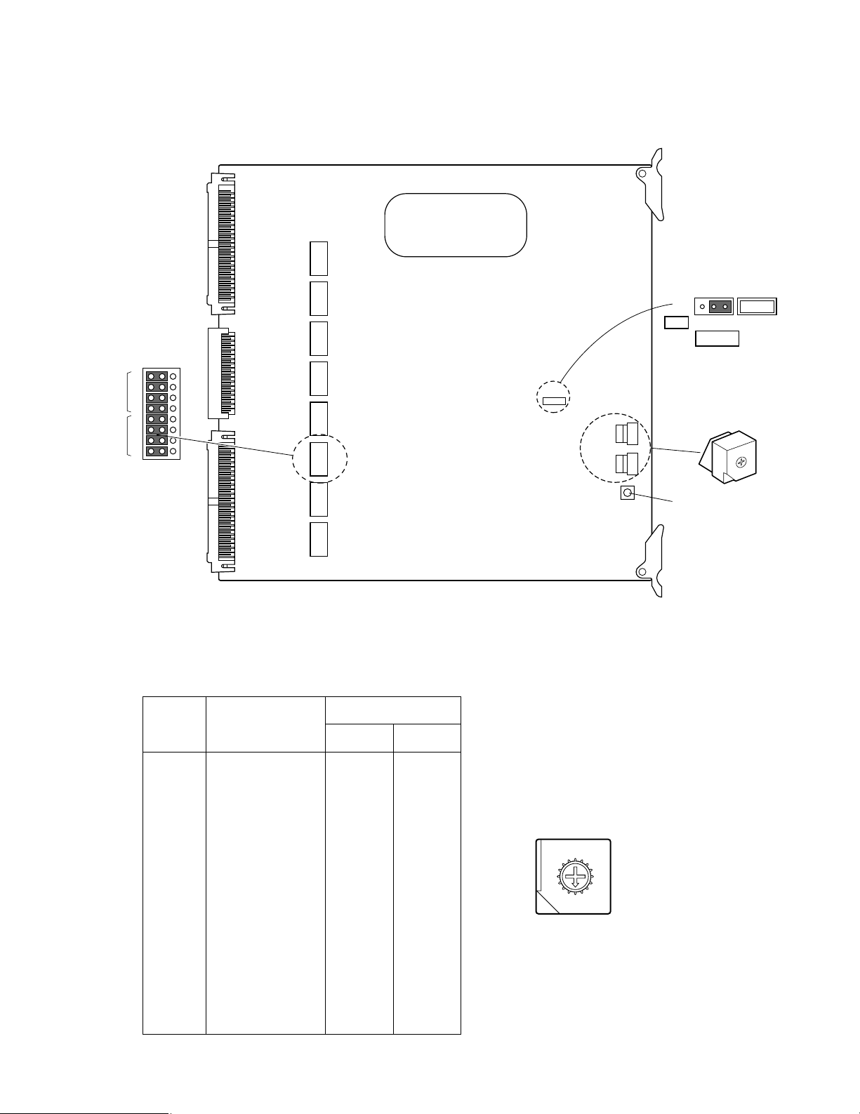
■Board Setting
Before installing this board, the following settings should be made by qualified service personnel or system installers.
CN 290 CN 250 CN 210 CN 170 CN 130 CN 90 CN 50 CN 10
ALARM OUTPUT BOARD
0
1
2
3
4
5
6
7
8
9
A
B
C
D
E
F
21
22
23
24
21
22
23
24
NO/NC
GND/COM
CN210
SW 2
CN4
SW 1
SW 3
CN4
13
NOR
INV
Polarity
Reset Switch
Board
No.
Alarm Output
SW Positions
SW2 SW1
1
2
3
4
5
6
7
8
9
10
11
12
13
14
15
16
0
0
0
0
0
0
0
0
0
0
0
0
0
0
0
0
0
1
2
3
4
5
6
7
8
9
A
B
C
D
E
F
1 - 32
33 - 64
65 - 96
97 - 128
129 - 160
161 - 192
193 - 224
225 - 256
257 - 288
289 - 320
321 - 352
353 - 384
385 - 416
417 - 448
449 - 480
481 - 512
1. Set switches (SW1 and SW2) on the board to designate the Alarm Output board number as shown in the following table.
The factory default setting is Board Number 1 (00).
8
9
A
B
C
D
E
F
0
1
2
3
4
5
6
7
Page 3

-3-
2. Position jumper connectors (CN10, CN50, CN90,
CN130, CN170, CN210, CN250, and CN290) on the
board to meet the alarm output requirements.
Select either Normally Open (N.O) or Normally
Closed (N.C) for the contact output, and then confirm that the jumper connectors are positioned at
Ground (GND) as shown below.
The factory default settings are Normally Open
(N.O).
21
22
23
24
21
22
23
24
NO/NC
GND/COM
CN210
Normally Open (N.O)
Default Setting
Normally Closed (N.C)
Ground (GND)
Default Setting
■Installation
The following installation should be made by qualified
service personnel or system installers.
● Installing Additional Extension
Boards
1. Remove the screws from the rear panel(s) of the
WJ-SX850 Matrix Switcher Card Cage.
2. Remove the rear panel(s).
3. Remove the front panel of the cage by removing the
two screws on the panel shown below.
3. Confirm that the jumper connector (CN4) on the
board is positioned on 1 and 2.
This setting lets you select the output polarity.
CN4
13
NOR
INV
Polarity
Default Setting
Page 4

4. Place the Boards into the specified positions in the
front or rear of the Cage by sliding them along the
board guides as shown below.
5. Make sure to push in the Boards until they are seated firmly.
6. Secure the rear board by tightening the two screws
on the board.
■Specifications
Alarm Output (1 - 32): 24V DC 500 mA maximum
Normally Open or Normally Closed selectable
37-pin D-sub connector
Dimensions: Front Board; 255(W) x 250(H) x 12(D) mm
10-1/16”(W) x 9-13/16”(H) x 1/2”(D)
Rear Board; 117.5(W) x 265(H) x 20(D) mm
4-5/8”(W) x 10-7/16”(H) x 13/16”(D)
Weight: 0.5 kg (1.1 lbs)
Weight and dimensions indicated are approximate.
Specifications are subject to change without notice.
NM1099-0 YWV8QA5060AN Printed in Japan
N 19
© Matsushita Communication Industrial Co., Ltd. 1999
Panasonic Canada Inc.
5770 Ambler Drive, Mississauga,
Ontario, L4W 2T3 Canada (905)624-5010
Panasonic Sales Company
Division of Matsushita Electric of Puerto Rico Inc.
Ave. 65 de Infanteria. Km. 9.5
San Gabriel Industrial Park, Carolina,
Puerto Rico 00985 (809)750-4300
Panasonic Security and Digital Imaging Company
A Division of Matsushita Electric Corporation of America
Executive Office: One Panasonic Way 3E-7, Secaucus, New Jersey 07094
Regional Offices:
Northeast: One Panasonic Way, Secaucus, NJ 07094 (201) 348-7303
Southern: 1225 Northbrook Parkway, Suite 1-160, Suwanee, GA 30024 (770) 338-6838
Midwest: 1707 North Randall Road, Elgin, IL 60123 (847) 468-5211
Western: 6550 Katella Ave., Cypress, CA 90630 (714) 373-7840
Board
Tighten screws
Tighten screws
Rear
panel
Rear
panel
Tighten screws
7. Close open spaces on the rear of the Cage with the
supplied rear panel(s).
8. Close the front of the cage by fixing the front panel.
 Loading...