

Page 1

-1-
q
w
1
2
VIDEO IN
1
2
VIDEO OUT
INPUT
■Preface
The WJ-PB85C16 Cross Point Input Board is an optional board for expanding the cross point input capability of the System
850 Matrix Switcher.
■Appearance
q Video Input Port (VIDEO IN, 1 - 2)
These ports accept either video signal from the VIDEO OUT port on the Camera Input Board of the Camera Control
Cage (MXCONT) or from the VIDEO OUT port on the Cross Point Input Board of another Cross Point Cage (MXSW).
Before attempting to connect or install this product,
please read these instructions carefully and save this manual for future use.
Extend Card (Cross Point in)
Model No. WJ-PB85C16
17
16
15
14
5
4
3
2
1
20
19
18
8
6
23
22
21
11
10
9
7
25
24
13
12
1
VIDEO 1
VIDEO 2
VIDEO 3
VIDEO 4
VIDEO 5
VIDEO 6
VIDEO 7
VIDEO 8
Not Used
Not Used
Not Used
Not Used
Pin No. Designation
25
24
23
22
21
20
19
18
17
16
15
14
Pin No. Designation
13
12
11
10
9
8
7
6
5
4
3
2
1
Ground
Ground
Ground
Ground
Ground
Ground
Ground
Ground
Ground
Ground
Ground
Ground
Ground
17
16
15
14
5
4
3
2
1
20
19
18
8
6
23
22
21
11
10
9
7
25
24
13
12
2
VIDEO 9
VIDEO 10
VIDEO 11
VIDEO 12
VIDEO 13
VIDEO 14
VIDEO 15
VIDEO 16
Not Used
Not Used
Not Used
Not Used
Pin No. Designation
25
24
23
22
21
20
19
18
17
16
15
14
Pin No. Designation
13
12
11
10
9
8
7
6
5
4
3
2
1
Ground
Ground
Ground
Ground
Ground
Ground
Ground
Ground
Ground
Ground
Ground
Ground
Ground
w Video Output Port (VIDEO OUT, 1 - 2)
The video signal connected to the VIDEO IN port is looped through to these ports.
If video output extensions are required, connect between these ports and the VIDEO IN ports
on the WJ-PB85C16 Cross Point Input Board of another Cross Point Cage (MXSW) for switching camera input.
Hold this board only by its edges. Otherwise components on the board may be damaged by static electricity.
Caution
Page 2

-2-
SW903SW902
0
1
2
3
4
5
6
7
8
9
A
B
C
D
E
F
CN151 CN101
CN251 CN201
CN351 CN301
CN451 CN401
CN551 CN501
CN651 CN601
CN751 CN701
CN851 CN801
VIDEO CROSS POINT
CN151
2
19
10
CN101
2
19
10
SW951
Reset Switch
Board
No.
VIDEO IN/OUT
SW Positions
SW903 SW902
1
2
3
4
5
6
7
8
9
10
11
12
13
14
15
16
0
0
0
0
0
0
0
0
0
0
0
0
0
0
0
0
0
1
2
3
4
5
6
7
8
9
A
B
C
D
E
F
1 - 16
17 - 32
33 - 48
49 - 64
65 - 80
81 - 96
97 - 112
113 - 128
129 - 144
145 - 160
161 - 172
172 - 192
193 - 208
209 - 224
225 - 240
241 - 256
1. Set switches (SW902 and SW903) on the board to designate the Cross Point Input board number as shown in the following table.
The factory default setting is Board Number 1 (00).
8
9
A
B
C
D
E
F
0
1
2
3
4
5
6
7
■Board Setting
Before installing this board, the following settings should be made by qualified service personnel or system installers.
Page 3
-3-
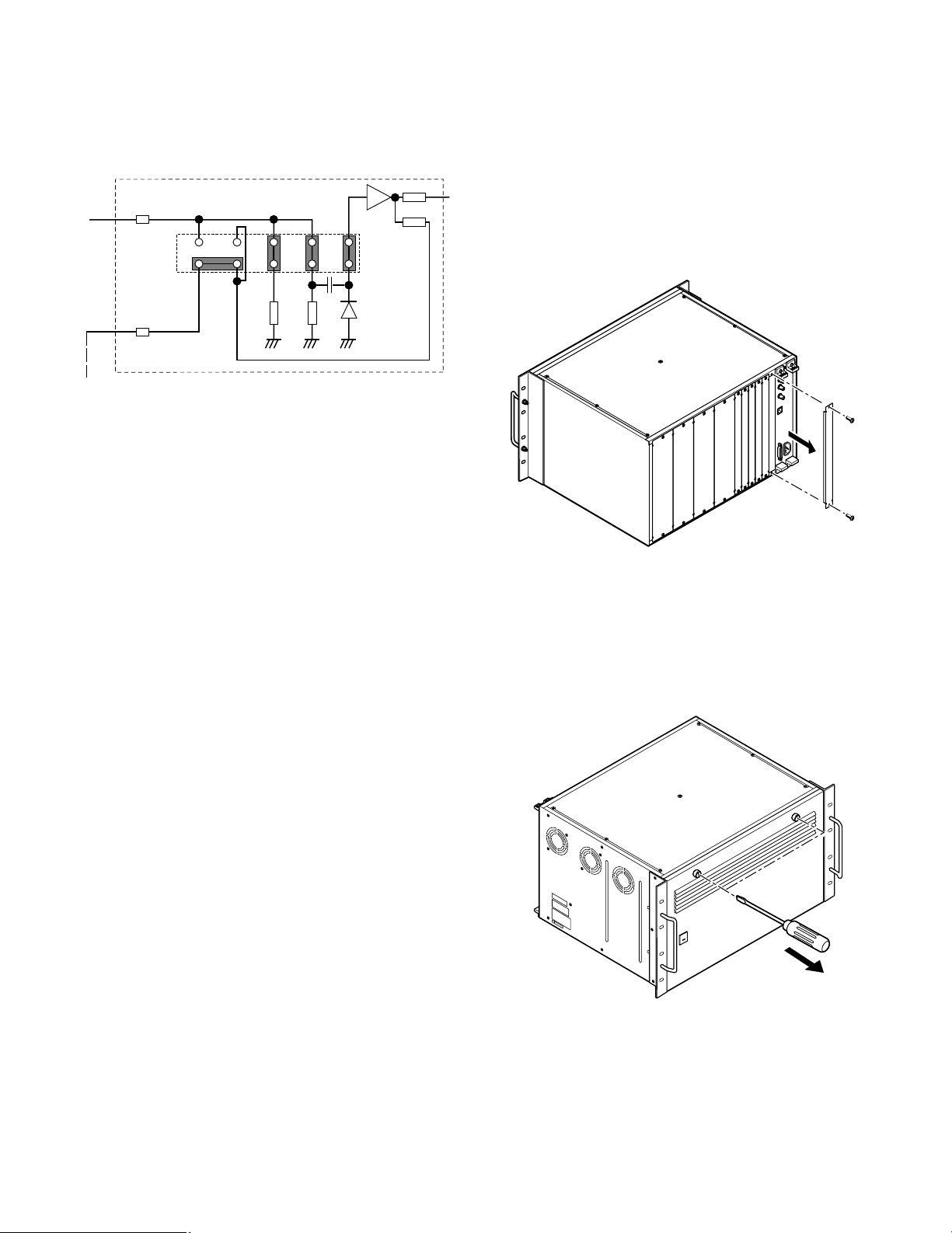
2. Position jumper connectors (CN101, CN151,
CN201, CN251, CN301, CN351, CN401, CN451,
CN501, CN551, CN601, CN651, CN701, CN751,
CN801, and CN851) on the board as shown below.
246810
1579
75 Ω
75 Ω
Clamping
Circuit
VIDEO IN
VIDEO OUT
3
Cross-point input for 1 channel
■Installation
The following installation should be made by qualified
service personnel or system installers.
● Installing Additional Extension
Boards
1. Remove the screws from the rear panel(s) of the
WJ-SX850 Matrix Switcher Card Cage.
2. Remove the rear panel(s).
3. Remove the front panel of the cage by removing the
two screws on the panel shown below.
The jumper connector positions designate the following functions as shown below.
• Video Input Termination
5 and 6 Closed: 75 Ω termination
5 and 6 Open: High Z (impedance) termina-
tion
• Clamping Circuit
8 and 10 , 7 and 9 Closed: Off
7 and 8 , 9 and 10 Closed: On
• Video Output Mode
1 and 2 , 3 and 4 Closed: Wired Loop Through
1 and 3 , 2 and 4 Closed: Buffered Through
For detail settings, refer to the appendix on page 5.
Page 4

4. Place the Boards into the specified positions in the
front or rear of the Cage by sliding them along the
board guides as shown below.
5. Make sure to push in the Boards until they are seated firmly.
6. Secure the rear board by tightening the two screws
on the board.
Board
Tighten screws
Tighten screws
Rear
panel
Rear
panel
Tighten screws
7. Close open spaces on the rear of the Cage with the
supplied rear panel(s).
8. Close the front of the cage by fixing the front panel.
-4-
Page 5

-5-
■Appendix
● Jumper Connector Positions for Cage Extension
Examples of jumper connector settings are shown below.
246810
1579
75 Ω
75 Ω
Clamping
Circuit
VIDEO IN
VIDEO OUT
2468
153
3
7
10
9
75 Ω
75 Ω
Clamping
Circuit
VIDEO IN
VIDEO OUT
2468
1
3
57
10
9
75 Ω
75 Ω
Clamping
Circuit
VIDEO IN
VIDEO OUT
Cross-point input for 1 channel
75 Ω input, Buffered through, Clamp ON
75 Ω input, Buffered through, Clamp OFF
HI-Z input, Wired through, Clamp off
Initial-stage cage:
• Video input is received at the input circuit terminated at 75 Ω.
• The through circuit used to transfer the same input
signal to another cage is buffered in this cage
before 75 Ω transmission.
• The signal output is clamped before sending it out
to the board circuit to adjust the black level to that of
another input signal.
Middle-stage cage: Other than the initial and
final stages
• No clamping circuit is required because the signal
input has already been clamped at the initial stage
and buffered by the DC amplifier.
• To transfer the same input signal to the next-stage
cage, position the jumper connectors for wired loopthrough. With a wired system, a failure of the power
supply to the middle-stage cage would not cause
any problem in the successive stages.
Note: If the video output is 65 or above, this middle-
stage cage may need further extension.
Final-stage cage:
• In the final stage, the signal sent from the initial
stage is matched to 75 Ω. The video signal therefore
is received at the input circuit terminated at 75 Ω.
• No clamping is required here because the signal
input is already clamped as in the middle stage.
• The output signal for monitoring and other equipment is buffered through.
Page 6

-6-
246810
13579
75 Ω
75 Ω
Clamping
Circuit
VIDEO IN
VIDEO OUT
246810
13579
75 Ω
75 Ω
Clamping
Circuit
VIDEO IN
VIDEO OUT
246810
13579
75 Ω
75 Ω
Clamping
Circuit
VIDEO IN
VIDEO OUT
Hi-Z input, Wired through, Clamp on
Hi-Z input, Wired through, Clamp on
Hi-Z input, Wired through, Clamp on
Cross-point input for 1 channel
Initial-stage cage:
• Video input is received at the input circuit terminated at a high impedance.
• Wire the through circuit to be used for transferring
the same input signal to another cage.
• The signal output is clamped before sending it out
to the board circuit to adjust the black level to that of
another input signal.
Middle-stage cage:
• Position the jumper connectors as for the initial
stage cage.
Final-stage cage:
• Position the jumper connectors as for the initialstage cage.
• When the jumper connectors are in this position,
there is no 75 Ω drive for VIDEO OUT. If output is
required at 75 Ω termination, change jumper positions 1-2 and 3-4 to 1-3.
● Jumper Connector Positions for Cage Extension
When the input video signal is terminated at another unit and it need be received at a Hi-Z impedance, position jumper connectors on the board to the position shown below.
Page 7

-7-
■Specifications
VIDEO Input (1 - 2): 1.0 V[p-p]/75 Ω composite video signal
8 inputs 25-pin D-sub connector (x2)
Video Output (1 - 2): 1.0 V[p-p]/75 Ω composite video signal
8 outputs 25-pin D-sub connector (x2)
Dimensions: Front Board; 255(W) x 250(H) x 12(D)
10-1/16”(W) x 9-13/16”(H) x 1/2”(D)
Rear Board; 117.5(W) x 265(H) x 20(D)
4-5/8”(W) x 10-7/16”(H) x 13/16”(D)
Weight: 0.5 kg (1.1 lbs)
Weight and dimensions indicated are approximate.
Specifications are subject to change without notice.
Page 8

NM1099-0 YWV8QA5056AN Printed in Japan
N 19
© Matsushita Communication Industrial Co., Ltd. 1999
Panasonic Canada Inc.
5770 Ambler Drive, Mississauga,
Ontario, L4W 2T3 Canada (905)624-5010
Panasonic Sales Company
Division of Matsushita Electric of Puerto Rico Inc.
Ave. 65 de Infanteria. Km. 9.5
San Gabriel Industrial Park, Carolina,
Puerto Rico 00985 (809)750-4300
Panasonic Security and Digital Imaging Company
A Division of Matsushita Electric Corporation of America
Executive Office: One Panasonic Way 3E-7, Secaucus, New Jersey 07094
Regional Offices:
Northeast: One Panasonic Way, Secaucus, NJ 07094 (201) 348-7303
Southern: 1225 Northbrook Parkway, Suite 1-160, Suwanee, GA 30024 (770) 338-6838
Midwest: 1707 North Randall Road, Elgin, IL 60123 (847) 468-5211
Western: 6550 Katella Ave., Cypress, CA 90630 (714) 373-7840
 Loading...