

Page 1

Model No. WJ-PB65E01
V
id
e
o
O
u
tp
u
t B
o
a
r
d
1
O
n
ly
N
e
w
o
rk
O
U
T
X
-1
A
L
A
R
M
O
U
T
1
A
L
A
R
M
O
U
T
2
1
0
/1
0
0
B
A
S
E
-
T
Before attempting to connect or operate this product, please read these instructions carefully and save this manual for future use.
Trademarks and Registered Trademarks
Network Board
Operating Instructions
• Microsoft and Windows are either registered trademarks or trademarks of Microsoft Corporation in the
United States and/or other countries.
• Intel and Pentium are trademarks or registered trademarks of Intel Corporation or its subsidiaries in the
United States and other countries.
Precautions
CAUTION: These servicing instructions are for use by qual-
ified service personnel only. To reduce the risk of electric shock do not perform any servicing other than that
contained in the operating instructions unless you are
qualified to do so.
• Do not attempt to disassemble the apparatus.
To prevent electric shock, do not remove screws or
covers.
There are no user-serviceable parts inside. Contact
qualified service personnel for maintenance.
• Other names of companies and products contained in
these operating instructions may be trademarks or registered trademarks of their respective owners.
• Do not strike or give a strong shock to the apparatus.
It may cause damage or allow water to enter the apparatus.
• Pay attention to static electricity
Make certain to keep boards inside the anti-static sack
until it is installed.
Put your hand on a metallic surface, other than the
boards to discharge static electricity before installation.
Do not touch components mounted on the boards
directly by hand.
Hold only both edges of the boards when installing.
References
Along with this document, refer to Central Processing Unit
WJ-MPU955A Operating Instructions for major operating
Preface
Network Board WJ-PB65E01 is designed for the connection
with Central Processing Unit WJ-MPU955A and system
controls, their functions, and switch settings.
expansion of Matrix Switcher WJ-SX650 Series.
Page 2
Features
• With this board, the network connection between
Central Processing Unit WJ-MPU955A and Matrix
Switcher WJ-SX650 Series becomes available to
expand the system composition. Up to 512 cameras
and 64 monitors become connectable.
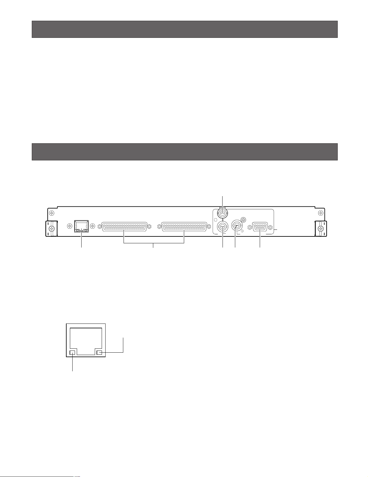
Major Operating Controls and Their Functions
■ Front View
e
10/100 BASE-T
q r yt
ALARM OUT 2
w
q Ethernet Port (10/100BASE-T)
This port is used for connection with Central Processing
Unit WJ-MPU955A via an Ethernet network.
LINK indicator: This indicator lights up when the matrix
switcher is linked to a network through this port.
ACT indicator: This indicator lights up when the matrix
switcher receives or sends data through this port.
LINK indicator
ACT indicator
ALARM OUT 1
VS IN
VS OUT
(THRU)
VS OUT
SERIAL
Video Output Board 1 Only
e VS Input Connector (VS IN)
Accepts a VS input signal from an external device.
r VS Output Loop-thru Connector (VS OUT (THRU))
Loops through VS input signals supplied to e.
t VS Output Connector (VS OUT)
Supplies VS output signals to external devices. While e
is accepting a VS input signal, t supplies an output
signal synchronizing the VS input signal. While e is not
accepting the VS input signal, t supplies an internal
synchronization output signal.
y Serial Port (SERIAL)
Connects to a PC.
NETWORK OUT X-1
w Alarm Output Ports 1, 2 (ALARM OUT 1, 2)
Supplies alarm output signals controlled by Central
Processing Unit WJ-MPU955A.
Note: Refer to WJ-SX650 Series Operating Instructions
for the ALARM OUT port details. (Pin Nos. 3, 5, 7, 9,
12, 14, 16, 18, 36, and 37 are unavailable.)
2
Page 3
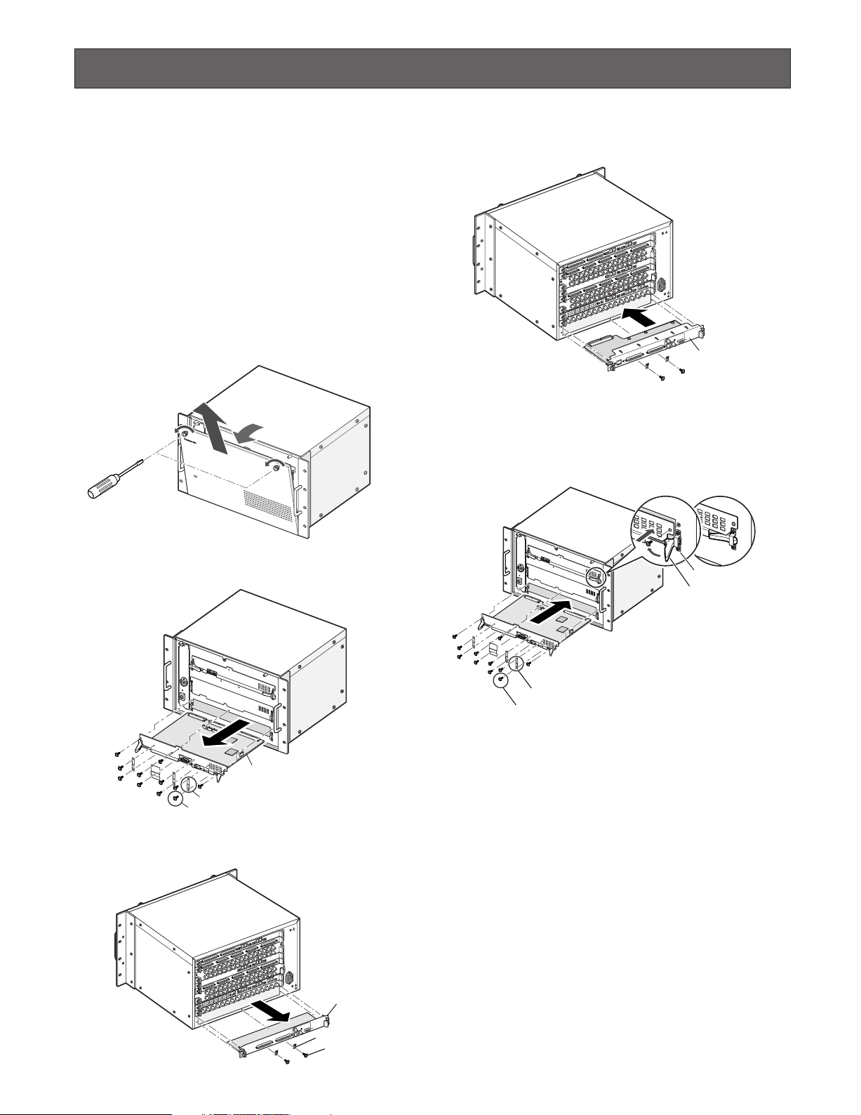
Board Mounting Procedure
The following example is the procedure to mount a network
board into the OUT X-1 slot of WJ-SX650 Series.
Notes:
• This network board can be inserted into the OUT X-1
slot only.
• Before the procedure, power off WJ-SX650 Series.
• Remove the screws and fixing brackets surely when
dismounting.
• Fix the screws surely when mounting.
• Do not hit the boards against the chassis of WJ-SX650
Series.
1. Remove the front panel by loosening the screws.
O
P
E
R
A
T
E
M
a
tr
ix
S
w
itc
h
e
r
W
J
-
S
X
650
4. Mount the network board into the OUT X-1 slot, and fix
the board with the supplied screws.
SIGNAL GND
D
N
G
L
A
N
G
I
N
O
.
M
R
E
T
F
F
N
O
O
.
M
R
E
T
E
D
O
M
TA 1
DA
E
D
O
M
L5
A 2
MN
T
DAT
A
T
A
D
S
6
P
/
A 3
NL
1
L
M
N
AT
T
M
D
T
7
2
NL
L
MN
/TM
A 4
T
DR3
DAT
H
NL3
L8
TM
/TMN
R1/
HD
DR4
H
L4
2
MN
rd
2/T
oa
DR
H
tput B
u
O
rd 1
Video
tput Boa
Ou
eo
Vid
S
Network board
5. Mount the video output main board by hooking the
board stoppers on the board stopper angles at the front
side, by pushing down the board stoppers, and by fixing the screws. Then, attach the front panel.
2. Dismount the video output main board from the front
side.
Video output main board
Fixing brackets (x4)
Screws (x8)
3. Dismount the OUT X-1 board from the rear side.
D
N
G
L
A
N
IG
S
Board stopper angle
Board stopper
Hook the board stoppers
on the board stopper angles, and
push down the board stoppers.
Fixing brackets (x4)
Screws (x8)
• Mount the main board into the slot.
• Fix the board with the screws (x3).
• Attach the fixing brackets (x4) with the screws (x8).
Note: When mounting, insert the main board surely into
slits.
D
N
G
L
A
N
G
I
TERM.ON
FF
ON
TERM.O
1
MODE
A
T
A
D
MODE
5
L
2
N
A
M
T
T
A
D
A
T
A
D
S
6
L
P
3
/
A
N
1
L
T
M
N
A
T
M
D
T
7
L
2
N
L
M
N
4
M
/T
A
3
T
T
R
A
D
D
H
3
L
8
N
L
M
N
/T
M
1
/T
R
4
D
R
H
D
H
4
L
N
2
M
d
r
/T
a
2
o
R
t B
D
u
H
tp
u
O
1
o
d
e
r
d
i
a
o
V
t B
u
tp
u
O
o
e
d
i
V
S
OUT X-1 board
Fixing brackets (x2)
Screws (x2)
3
Page 4

Firmware Update
This chapter explains about how to update the firmware
version of WJ-SX650 Series. To update the firmware version, installation of the Firmware update tool on the PC is
required.
■ System Requirements of a PC
The PC should meet the following requirements.
OS:
Microsoft®Windows®2000 Professional SP4
Microsoft
Microsoft
Note: To work the Firmware update software on the PC,
OS language:
English
PC:
IBM PC/AT Compatible
®
Windows®XP Professional SP2
®
Windows®XP Home Edition SP2
Microsoft
®
.NET Framework 1.1 needs to be installed.
If you try to install the Firmware update software on a
PC without Microsoft
®
.NET Framework 1.1, it will be
installed along with the software.
■ Installation and Uninstallation
● Installation
1. Insert the supplied CD-ROM into the CD-ROM drive on
the PC.
2. Double-click "setup.exe" in the "PWriter" folder of CDROM.
The installation wizard will be displayed on the PC
screen.
3. Follow the instruction message on the PC screen to
complete the installation.
Note: In the factory default installation, C:\Program
Files\Panasonic\Firmware is created, and files will be
copied to the directory.
● Uninstallation
1. Select "Control Panel" - "Add/Remove Programs".
Add/Remove Programs window will be displayed on the
PC screen.
2. Select "Firmware version up software". Click "Remove"
or "Change/Remove", and follow the directions.
CPU:
Intel®Pentium®3, 500 MHz or faster
Memory:
128 MB or more
Hard drive space:
30 MB or more for installation of the Firmware update software
50 MB or more for installation of WJ-SX650 Series Initial
Setup Tool
Note: If Microsoft
®
.NET Framework 1.1 has not been
installed on the PC, 160 MB or more is required.
Monitor:
1 024 x 768 pixels or more, HIGH color 16 bit or more
Serial Interface:
9-pin D-sub connector
Note: If the Firmware update software has already been
installed on a PC, installation is impossible.
Install the application again after uninstallation.
■ PC Connection
An RS-232C crossing cable (9-pin D-sub) is used for connection between WJ-SX650 Series and PC.
<SERIAL port> (Output rear board)
Rear Side of WJ-SX650 Series
(WJ-PB65E01 installed)
EXTENSION 2 IN
EXTENSION 3 IN
VIDEO OUT 3
VIDEO OUT 4
31 30
29 28
163215
14 13
12 11
DATA 1
DATA 2
DATA 3
DATA 4
TMNL5
TMNL6
HDR3/TMNL7
HDR4/TMNL8
Video Output Board 2
TMNL2
HDR1/TMNL3
HDR2/TMNL4
TMNL1/PS DATA
Video Output Board 1
10/100 BASE-T
ALARM OUT 2
27 26
TERM.ON
MODE
VIDEO OUT 2
10 9
TERM.OFF
ON
MODE
4
RS485 (CAMERA) RS485 (CAMERA)
MODE
248723 226521
25
CAMERA IN
4
RS485 (CAMERA) RS485 (CAMERA)
MODE
DATA
910111213141516
MONITOR OUT
ALARM OUT 1
21
3
MODE MODE MODE
VIDEO OUT 1
2
3
MODE MODE MODE
VS IN
VS OUT
VS OUT
(THRU)
ALARM IN
204319 182117
1
1234
OFF
ON
DATA
MODEMODEMODEMODE
EXTENSION 1
IN
OUT
TERM.
Video Output Board 1 Only
NETWORK OUT X-1
SERIAL
9-pin D-sub
(Female)
C
SIGNAL GND
3
IN C-3
2
IN X-2
RS485(CAMERA) SET UP
ON
4-Line
MODE
ON
4-Line
1
MODE
IN X-1
B
3
IN B-3
2
1
A
AC IN
3
OUT X-3
2
12345678
OUT X-2
SIGNAL GND
1
9-pin D-sub
(Female)
PC
Cross cable
4
Page 5

<TEST port> (Output front board)
Front side of WJ-SX650 Series
(Front panel detached)
No.
RESET
MODE
PULL
POWER
ON
OFF
TEST
RESET
MODE
9-pin D-sub
(Female)
Cross cable
9-pin D-sub
(Female)
PC
■ Firmware Update Procedure
Note: The following is the procedure when using the
Windows XP operating system.
If you performed wrong operations, the monitor display
will return to Step 3. In this case, retry the operations.
1. Select "Start" - "All Programs" - "Panasonic" - "Firmware
version up software" - "Firmware version up software
x.xx". (x.xx is the version number.) Then, run the program.
2. Firmware update software will start up, and the login
window will be displayed on the PC screen.
4. The following message will be displayed. Then, click
"OK".
5. "File Selection" window is displayed.
Click "Browse" to select the firmware file of WJ-SX650
Series for update.
The file is located in the following directory.
E:\PWriter\SX650_vXXXXX_yyyy.mot
(E is the CD-ROM drive, "X" is the software version, and
"y" is the checksum.)
Enter the user name and password. The factory default
is as follows.
User Name: user
Password: 12345
3. Click "OK". "Firmware update software" window is displayed. Then, click "WJ-SX650 Series".
Note: Make a note of version displayed in the "File
Selection" window. The version will be required for
checking in Step 7.
6. Connect the SERIAL port of WJ-SX650 Series and PC.
(Refer to the illustration of <SERIAL port> in p. 4.)
Then, perform the firmware update by following the
instructions given.
Notes:
• Firmware update procedure is as follows:
Current version check → Firmware update → New
version check
If the current version is the same as the version you
have noted down in Step 5, firmware update is not
required.
• When the "Version check completed" message or
"Firmware update confirmation" message appears during firmware update, reconnect the cable (SERIAL port
↔ TEST port) and perform the MODE switch setting of
video output board for update.
SERIAL port: Connected for version check
TEST port: Connected for firmware update
5
Page 6

7. When finishing the firmware update, "Completed" window is displayed.
WJ-SX650 Series Initial Setup Tool
Check that the version of Video Output Board 1 is the
same as the version you have noted down in Step 5.
Notes:
• To prevent misuse, be sure to change the factory
default user name and password. The user name and
password can be changed by clicking "User setup" and
changing the settings.
• If the matrix switcher has Video Output Board 2, update
the firmware version of Video Output Board 2 by performing Step 3 to 7.
This chapter explains about WJ-SX650 Series Initial Setup
Tool. Before controlling WJ-SX650 Series Initial Setup Tool,
installation on the PC is required.
■ Features
WJ-SX650 Series Initial Setup Tool is used for special configuration of Matrix Switcher WJ-SX650 Series with network
card. (Usually, the modification of default configuration is
not required when a network card is installed.)
WJ-SX650 Series Initial Setup Tool has the following configuration menus:
• RS485 Camera
This menu is used for RS-485 camera settings.
Factory default: All coaxial cameras
Note: WJ-MPU955A Administration Console cannot config-
ure the RS-485 camera settings for the matrix switcher.
• OSD Character Font
This menu is used for adjusting the OSD font. When a user
set the camera title with WJ-MPU955A Administration
Console, the expected font is not displayed on monitors.
However, the user can change the SX650 Text Code by
selecting from the font list.
Factory default: Normal ASCII code
■ Installation and Uninstallation
● Installation
1. Insert the supplied CD-ROM into the CD-ROM drive on
the PC.
2. Double-click "setup.exe" in the "Setup_Tool" folder of
CD-ROM.
The installation wizard will be displayed on the PC
screen.
3. Follow the instruction message on the PC screen to
complete the installation.
Note: In the factory default installation, C:\Program Files\
Panasonic\WJ-SX650Cnfg is created, and files will be
copied to the directory.
● Uninstallation
1. Select "Control Panel" – "Add/Remove Programs".
"Add/Remove Programs" window will be displayed on
the PC screen.
2. Select "WJ-SX650 Series Initial Setup Tool".
• Alarm Input State
In this menu, the user can reverse Normally Open contact
and Normally Close contact for alarm input ports.
Factory default: Normally Open
• Ethernet Communication
This menu is used for the Ethernet Communication
Property. Select "Auto Negotiation".
Factory default: Auto Negotiation
6
3. Click "Remove" or "Change/Remove", and follow the
directions.
Note: If WJ-SX650 Series Initial Setup Tool has already
been installed on a PC, installation is impossible. Install
the application again after uninstallation.
Page 7

■ Starting Up
■ Window Details
Note: The following is the procedure when using the
Windows XP operating system.
1. Select "Start" – "All Programs" – "Panasonic" – "WJSX650 Series" – "WJ-SX650 Series Initial Setup Tool
x.xx". (x.xx is the version number.) Then, run the program.
WJ-SX650 Series Initial Setup Tool will start up, and the
login window will be displayed on the PC screen.
2. Enter the user name and password. The factory default
is as follows.
User Name: admin
Password: sx650
3. Click "OK". "WJ-SX650 Series Initial Setup Tool" window
is displayed.
qwert y u io
!0
!1 !2 !3
● Tool Bar
q : Downloads the current setup data of WJ-SX650
Series to the PC.
4. To download setting data from WJ-SX650 Series, click
on the icon pointed in the illustration. "Download" window will be displayed.
5. Click on "Start Download". The setting data will be
downloaded from WJ-SX650 Series to the PC.
Note: Connect the SERIAL port of WJ-SX650 Series
and PC.
(Refer to the illustration of <SERIAL port> in p. 4.)
6. When download is complete, a message window is displayed. Then, click "OK". "RS485 Camera" – "RS485
Port" is displayed.
Note: If you upload the setting data from the PC to WJ-
SX650 Series while SETUP MENU is open on a monitor,
SETUP MENU will be closed forcibly. Settings performed in SETUP MENU will be canceled and replaced
by those uploaded from the PC.
w : Uploads the setup data (configured in WJ-SX650
Series Initial Setup Tool) from the PC to WJ-SX650
Series.
e : Creates the initial settings.
r : Opens the file in which the setup data was saved.
t : Saves the setup data as a file.
y : Displays the information of video input board/out-
put board.
u : Displays the user settings page.
i : Displays the settings page of SERIAL port.
o : Displays the version of WJ-SX650 Series Initial
Setup Tool.
!0 These buttons are clicked when setting categories are
selected.
!1 Setting details are displayed when !0 is clicked.
!2 : Determines the settings.
!3 : Clears the settings.
Notes:
• Do not edit the setup data files by using text editors,
etc. You may become unable to open the setup data
files.
• To perform q, w, and y, WJ-SX650 Series needs to
be connected to the PC with an RS-232C cable.
7
Page 8

Specifications
Ethernet Port: 10/100BASE-T, RJ-45 x 1
Alarm Output (ALARM OUT 1, 2)
Alarm Output: Open collector output x 32, Max. 24 V DC, 100 mA
VS Input: 1 V[P-P]/75 Ω (VS IN)
VS Output: (VS OUT (THRU)): VS loop-thru output
(VS OUT): 1 V[P-P]/75 Ω (VS)
Serial Port: 9-pin D-sub connector x 1
Dimensions
Network Board: 355 mm (W) X 38 mm (H) X 134 mm (D)
{14" (W) X 1-1/2" (H) X 5-3/10" (D)}
Standard Accessories
Operating Instructions (This Document) ................................................ 1 pc.
CD-ROM ................................................................................................. 1 pc.
Note: The files specified below are included on the CD-ROM.
WJ-SX650 Series Firmware
Program Writer (Firmware update tool)
WJ-SX650 Series Initial Setup Tool
Warranty Card ........................................................................................ 1 pc.
Panasonic System Solutions Company,
Unit Company of Panasonic Corporation of North America
Security Systems
www.panasonic.com/security
For customer support, call 1.877.733.3689
Executive Office: Three Panasonic Way 2H-2, Secaucus, New Jersey 07094
Zone Office
Eastern: Three Panasonic Way, Secaucus, New Jersey 07094
Central: 1707 N. Randal Road, Elgin, IL 60123
Southern: 1225 Northbrook Parkway, Suwanee, GA 30024
Western: 6550 Katella Ave., Cypress, CA 90630
Panasonic Canada Inc.
5770 Ambler Drive,Mississauga,
Ontario, L4W 2T3 Canada (905)624-5010
http://www.panasonic.ca
Panasonic Sales Company
Division of Panasonic Puerto Rico Inc.
San Gabriel Industrial Park 65th Infantry Ave. KM. 9.5 Carolina
P.R. 00985(809)750-4300
© 2006 Matsushita Electric Industrial Co., Ltd. All Rights Reserved. NM0806-2126 V8QA6477CN Printed in Japan
 Loading...