

Page 1

Operating Instructions
Network Disk Recorder
Model No. WJ-NX300K
WJ-NX300K/G
Network Disk Recorder WJ-NX300
Before attempting to connect or operate this product,
please read these instructions carefully and save this manual for future use.
The model number is abbreviated in some descriptions in this manual.
Page 2

CONTENTS
Preface .......................................................................4
About the user manuals .........................................4
Abbreviations .........................................................4
About the settings and operation of the
recorder .................................................................4
Restrictions when using this product .....................5
Before using this product ...........................................7
Motion detection (VMD) function ...........................7
Time display of recorded images ...........................7
Response to the mouse operations .......................7
Black screen displayed when playing recorded
images ....................................................................8
Recording operation ...............................................8
Event type ..............................................................8
Extra function .........................................................8
Configure the basic settings [Basic setup] .................9
Display the basic setup pages ...............................9
Set up date & time and language
[Date/Language] .....................................................9
Camera setup [Camera] .......................................12
Set up recording/events [REC & event] ................35
Configure the settings relating to monitors
[Monitor] ...................................................................46
Set up the main monitor [Main monitor] ...............46
Configure the settings relating to sub monitors
[Sub monitor] ........................................................48
Configure other settings relating to monitors
[Advanced setup] .................................................49
Configure the settings relating to network [Network]
Configure the basic network settings [Basic] .......50
Procedure to register information for the
"Viewnetcam.com" service ..................................52
Configure the settings relating to the mail
notification [e-Mail] ...............................................54
Configure the Panasonic alarm protocol settings
[Panasonic alarm protocol] ...................................55
Configure the settings relating to NTP/SNMP
synchronization [NTP/SNMP] ...............................56
Configure the settings relating to the user
management [User management] ............................57
Configure the basic settings relating to user
management [Basic] .............................................57
Register, edit or delete the user information
[User registration] .................................................59
Edit the administrator information [Administrator
setup]....................................................................61
Register, edit or delete host [Host registration] ....62
Configure the settings relating to maintenance
[Maintenance] ...........................................................63
Check the system information such as the version
[System information] ............................................63
Confirm the hard disk drive information
[HDD information] .................................................64
...50
Configure the settings and operations relating to
the system [System management] .......................66
Register the licenses for the recorder and the
additional camera [Registration of license] ..........68
Manage the hard disk drives [HDD management] ...71
How to display the "HDD management" page .....71
Check the hard disk drive information
[General] ...............................................................72
Format the hard disk drives [Format HDD] ..........72
About the removal process and the link process
of hard disk drives ................................................73
About the change of the HDD operational
mode ....................................................................74
Set the recording group
[Recording group setup] .......................................75
Configure the settings relating to the extra functions
[Extra function] .........................................................76
Lists of the setting items (Setup menu) ....................77
About the error logs and the network logs ...............92
Error logs ..............................................................92
About the network log ..............................................96
Operation window ....................................................97
Main monitor (A monitor to display the live image,
the playback image and the setup menu) ............97
Sub monitor (monitor for display of live images
only) ....................................................................101
Basic operations .....................................................102
Logout ................................................................102
Login operation at startup ......................................103
Monitor live images ................................................104
About the operation panel ..................................104
Switch between control screen and wide view
screen .................................................................109
1-screen display .................................................110
Display images from cameras on a
multiscreen .........................................................111
Use digital zoom .................................................112
Correct the fisheye image ..................................113
Operate the camera ...............................................114
Camera control panel .........................................114
Panning/Tilting ...................................................116
Zooming .............................................................116
Move to home position ......................................117
Focus adjustment ...............................................117
Iris (brightness) adjustment ................................117
Auto mode ..........................................................118
Register camera preset positions ......................119
Move camera preset positions ...........................119
AUX operation ....................................................120
Wiper operation ..................................................120
Register home position ......................................121
Execute auto back focus ....................................121
Set up mask areas ..............................................122
2
Page 3

Zoom/Focus adjustment ....................................122
Initial position setup ...........................................123
Event function ........................................................124
Action to be taken upon an event occurrence ...124
Stop buzzer beeping ..........................................125
Cancel the alarm action .....................................126
Cancel the error action .......................................126
Record images .......................................................127
Record images (Schedule recording) .................127
Emergency recording .........................................128
Play recorded images .............................................129
Playback operation panel ...................................131
Play images from a designated point .....................134
Play image recorded at a designated
date & time .........................................................134
Play the latest recorded image ...........................135
Playback by designating a timeline ....................136
Search and play ......................................................138
Play images selected from logs (Log search) .....138
Display thumbnail screen and paly back
(Thumbnail search) .............................................139
Search and play recorded images triggered by
motion detection (VMD search) ..........................140
Copy recorded images ...........................................143
Format USB medium ..........................................146
Play back copied images with this recorder ..........147
List of operation items ............................................149
Configure the network settings ..............................152
Configure the network settings of the
recorder ..............................................................152
Configure the network settings of the PC ..........152
Network security of the recorder ............................155
The security function of the recorder .................155
Enhance network security ..................................155
Display the operation window ................................157
About the operation window ..................................158
Top Page ............................................................158
Control panel ......................................................159
Camera selection panel ......................................160
Setup panel ........................................................161
Status display area .............................................162
Download operation area ...................................163
[CAM] tab ...........................................................163
[HDD] tab ............................................................164
Monitor live images ................................................165
Display images on a 1-screen ............................165
Display images on a 4-screen (multiscreen) .......166
Operate the camera ...............................................167
Panning/Tilting ...................................................167
Zooming .............................................................167
Focus adjustment ...............................................168
Iris (brightness) adjustment ................................168
Register preset positions ...................................168
Move to preset positions ....................................168
Auto mode/AUX/Wiper .......................................169
Event function ........................................................170
Action to be taken upon an event occurrence ...170
Cancel the alarm action .....................................171
Cancel the error action .......................................171
Play recorded images .............................................172
Play image recorded at a designated
date & time .............................................................174
Search and play recording events
(REC event search) .................................................175
Motion detection search and playback
(VMD search) ..........................................................177
Copy recorded images ...........................................179
Download recorded images currently being
played .....................................................................181
Check a list of copied recorded images .................183
Play back the copied/downloaded images on a
PC ...........................................................................185
To play recorded images copied on the media
device .................................................................185
Play recorded images downloaded using a web
browser ..............................................................185
Install the viewer software ..................................186
Uninstall the viewer software .............................186
How to use the viewer software .........................187
Setup ......................................................................191
Basic operations ................................................191
Configure the settings ........................................191
Set the web browser [Web browser] ..................192
Update the firmware ...........................................192
Notification by e-mail .............................................193
Alarm mail...........................................................193
Warning mail .......................................................193
Addendum ..............................................................195
In combination with the network microphone ....195
Concurrent user license function .......................201
Troubleshooting ......................................................202
Glossary .................................................................207
3
Page 4

Preface
About the user manuals
There are 4 manuals provided for the WJ-NX300K, WJ-NX300K/G as follows.
Installation Guide: Contains procedures how to install/connect this product, and descriptions of easy
congurations.
Important Information (PDF):
Contains preface, precautions, and major operating controls and their functions and
specications.
Operating Instructions (PDF: this document):
Contains descriptions of how to operate this product with a PC. Make sure to read
them when installing the recorder.
Quick Reference Guide: Contains descriptions of how to congure the basic settings and how to use the major
functions.
Adobe® Reader® is required to read the PDF les (the setup instructions and the operating instructions) on the
provided CD-ROM.
When Adobe® Reader® is not installed on the PC, download the latest Adobe® Reader® from the Adobe web
site and install it.
"NX300" shown in the instructions and illustrations used in these operating instructions indicate the WJ-NX300K,
WJ-NX300K/G.
Refer to "readme.txt" on the provided CD-ROM for further information about the optional dedicated software,
compatible network cameras (hereinafter, cameras) and their versions.
Refer to the Panasonic support website (https://security.panasonic.com/support) for latest information about
the compatible cameras and functions to be added or changed by rmware upgrade.
The external appearance in the document may differ from the actual product within no inuence range on operation
due to improvement of the product.
Abbreviations
The following abbreviations are used in this manual.
Microsoft® Windows® 8.1 is described as Windows 8.
Microsoft® Windows® 7 is described as Windows 7.
Windows® Internet Explorer® 11 is described as Internet Explorer.
Network cameras are described as cameras.
About the settings and operation of the recorder
• Professional knowledge and experience with the network, hard disk and network camera are required for
the setting and operation of the recorder.
• The recorder can be operated using the provided mouse connected to the USB port on the front side of the
recorder and the soft keyboard. Refer to "Basic operations" of Installation Guide for the operation of the
mouse and the soft keyboard.
• The camera settings are automatically done in accordance with recording settings of the recorder once the
camera is registered in the recorder. If you directly change settings related to image and audio of the camera registered in the recorder, the settings may differ from those of the recorder or some functions may not
work properly.
• It is also possible to perform settings and some operations of the recorder from the web browser. Refer to "Lists
of the setting items" on page 77 for setting items via the web browser and "List of operation items" on page
149 for operational items via the web browser. Refer to page 157 and following pages for the operation.
• This documents is sub headed in each applicable page such as "Setup via recorder's main monitor",
"Operation via recorder's main monitor", "Setup on browser" and "Operation via PC web browser".
• This document explains settings and operation of the recorder using 16 cameras as examples.
4
Page 5

Restrictions when using this product
When using this product, some functions have the following restrictions. Before using this product, keep the
following in mind.
When displaying live images from the
camera
• Black screen may be displayed for the rst several
seconds (*) when the following operations are performed while displaying live images.
• When live images are displayed (by switching
camera, etc.)
• When image is zoomed in or out
When playing recorded images
• First several seconds (*) may be skipped when the
following operations are performed while playing
recorded images.
• When cameras are switched
• When image is zoomed in or out (When zooming into/out of a paused recorded image, an
image occurring several seconds before or
after the displayed image may be zoomed in.)
• When the playback button is clicked again
while playing images
• When the rst frame is displayed by starting
the frame by frame playback during pausing
• Playback may be performed in several seconds
intervals (*) when the following operations are performed. Refer to the description of operations
during playback on pages 131 and 173 for how
to control playback.
• Reverse playback
• Fast playback/Fast reverse playback
• Reverse frame playback
• When playing images by designating date & time,
playback may start from a point several seconds*
before/after the specied time or from the rst
frame of the next record.
• When the latest recorded image is played, playback may start from a point several seconds
before/after a point that is 10 seconds before the
latest recorded image. The playback or audio output may be paused some ten seconds after the
start of the playback depending on the volume of
recorded image data. If the audio output stops,
pause playback and replay it again.
• When the frame rate is set to 25 ips ~ 60 ips,
recorded images may not be played smoothly.
• If the recorder cannot continue playback due to a
large load, it stops the playback and returns to the
live display.
When recording images
• The actual time of recording trigger (event occurrence time, start time of the schedule recording,
etc.) and the recording start time (time displayed
on the recording event list) may not exactly be the
same.
• When pre-event recording is set to be performed,
the recording may not be performed as the set
duration.
• If the frame rate is set to switch during the event
recording or the emergency recording, it may take
a few seconds to switch the rate depending on
the refresh cycle interval.
When copying images
Copying of recorded images may start from a point
several seconds (*) before the designated start time
when copying recorded images.
When downloading recorded images
Downloading of recorded images may start from a
point several seconds (*) earlier than the designated
start time.
* Time (seconds) differs depending on the refresh
interval setting of the camera (0.2 - 5 seconds). In
the recorder, the refresh interval setting of the camera is set to 1 second at the camera registration.
Refer to the operating instructions of the camera for
information about the refresh interval setting.
When using a USB memory stick/
external storage device
After a USB memory stick is inserted, it may take time
to recognize the medium. It also may take time if the
capacity size of the inserted media is large.
5
Page 6

When using the web browser
• If the camera is set to high frame rate and high
resolution, update of images may take time or
images may be displayed intermittently. If the
camera is used with the following settings, the
above may be improved by using a PC described
in the specications.
[Setting examples]
1-screen display Image capture size:
FHD (1920×1080), frame rate: 60 ips,
image quality: XF
1-screen display Image capture size:
HD (1280×720), frame rate: 60 ips,
image quality: XF
4-screen display Image capture size:
HD (1280×720), frame rate: 30 ips,
image quality: XF
[Specifications]
CPU: Intel® CoreTM i7 6700 or better
Memory: 8 GB (4 GB×2) or more
6
Page 7

Before using this product
Motion detection (VMD) function
The motion detection (VMD) function of cameras detects motions referring to changes of luminance (brightness)
in areas set in advance.
The motion detection function will not effectively work in the following situations or may sometimes be malfunctioning.
• When there is a very little difference in luminance (brightness) between a background and a subject
• When brightness of images is low such as at night
• When a subject moves very slow
• When a subject is very small
• When the amount of rays of light incidence changes frequently such as at a window or outdoors.
• When light such as sunlight or car headlight comes from outside
• When a uorescent lamp ickers
• When a subject has depth
When conguring the motion detection settings, check the function performance both in daytime and at night
after appropriately conguring the area settings and the sensitivity settings according to the camera installation
conditions and possible movement of subjects. When the detection function does not work or false detection
occurs, use a sensor separately. Refer to the operating instructions of the camera for further information.
Time display of recorded images
When displaying recorded images, the displayed date & time may sometimes skips. This is not a malfunction.
The displayed date & time on the monitor and the recorder may sometimes not be exactly the same. This is
also not malfunction.
Response to the mouse operations
While this recorder is processing multiple operations at the same time, the response to the operations from the
connected mouse may temporarily become slow. This is not a malfunction.
7
Page 8

Black screen displayed when playing recorded images
In the following cases, a black screen may be displayed during playing recorded images. However, this is not a
malfunction.
• When changing cameras or screen patterns during playback or pausing
• When skipping/reverse skipping during playback
• When fast forwarding/reverse fast forwarding during playback
• When the latest recorded image is played while displaying images on a multiscreen*
• When changing the selected camera during the multi-screen display
• When going to the next recording event list by fast forwarding/reverse fast forwarding or skipping/reverse
skipping during playback
• When playback operation is affected by another operation (such as when receiving multiple alarms sequentially or while copying is being performed simultaneously)
* Some camera images go black depending on the data volume.
Recording operation
The recorder can connect up to 32* cameras and record their images on the HDD.
The following recording operations are available.
Schedule recording: Recording that is automatically performed at the designated time range on the desig-
nated day(s) of the week
Event recording: Recording that is automatically performed when an event occurs (such as terminal
alarm/camera site alarm/command alarm, etc.)
Emergency recording: Gives priority to recording video and audio at emergency using the external switch
connected to the emergency record input terminal of the recorder.
* When registering the license for 32 cameras by the additional camera kit.
Important:
• Recording may not be performed for around 3 seconds in the following cases. However, this is not a malfunction.
• When the settings are changed and the setup menu is closed during recording
Event type
The following event recording types are displayed in list form on the web browser:
SCH: Schedule recording
EMR: Emergency recording
SD: SD backup rec.
The following are detailed event recording types.
COM: Displayed when a command alarm occurred
TRM: Displayed when a terminal alarm occurred
CAM: Displayed when a camera site alarm occurred
PRE: Pre-event recording
Extra function
To increase number of connected cameras, it is necessary to register the Additional Camera Kit (option) license.
To use the secure function, it is necessary to register the Secure Communication Kit (option) license.
To use the business intelligence function, it is necessary to register the additional business intelligence kit
(option) license.
To congure Mirroring (RAID1) or RAID5/RAID6, it is necessary to register the additional RAID Kit (option) license.
8
Page 9
[Setup via recorder's main monitor]
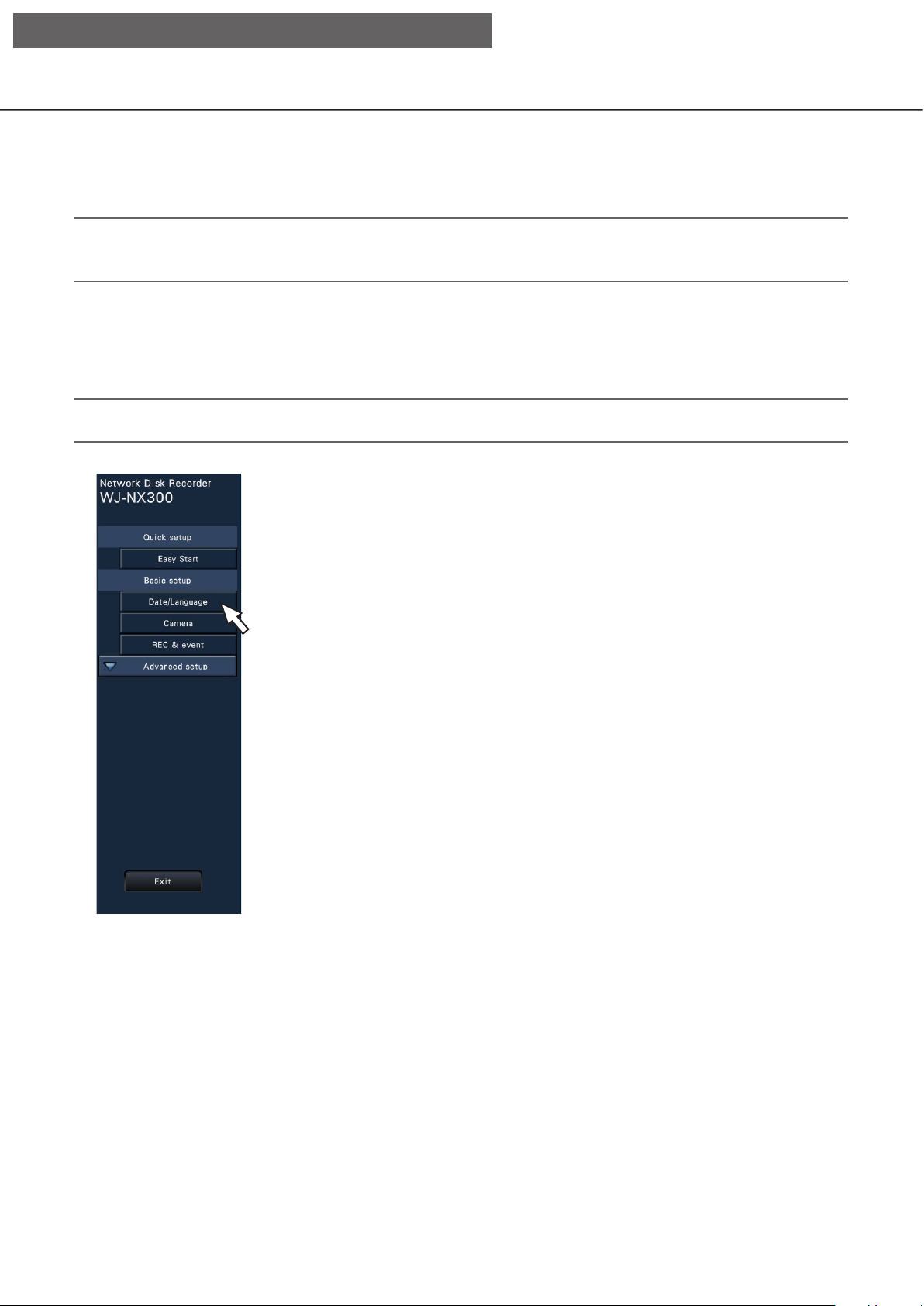
Configure the basic settings [Basic setup]
The basic settings of the recorder such as date & time and recording mode, etc. can be congured on the
"Basic setup" page.
The "Basic setup" page provides access to the [Date/Language], [Camera] and [REC & event] pages.
Note:
• Refer to "Congure the minimum settings [Easy Start]" of the Installation Guide for the [Quick setup] - [Easy
Start] of the setup menu.
Display the basic setup pages
Click the desired button on the setup menu.
Note:
• The setup menu can be displayed by clicking the [Setup] button on the operation panel of the operation screen.
[Date/Language] button: Displays the "Date/Language" page. Perform settings such as date & time and
daylight saving time.
[Camera] button: Displays the "Camera" page. Perform registration and setup of network cameras.
[REC & event] button: Displays the "REC & event" page. Congure the recording schedules and event
actions.
Set up date & time and language [Date/Language]
The "Date/Language" page has the [Date & time adjustment], [Date & time settings] and [Language] tabs.
9
Page 10

[Setup via recorder's main monitor]
[Date & time adjustment] tab
Set the current date & time.
■ Date & time
[Date]
Set the current date. Select the year, month and day
from the calendar.
[Time]
Set the current time.
[<<Y]/[Y>>] button: Selects the previous or next
year.
[<M]/[M>] button: Selects the previous or next
month.
Important:
• Click the [Apply] button after setting the date &
time. The second will be set to "00".
[Date & time settings] tab
Perform settings such as date & time format, time zone, daylight saving time, and time adjustment method.
[Time]
Select a time display format. (Example: 3 o’clock in
the afternoon)
24 h: 15:00:00
12 h: 03:00:00 PM
Default: 12 h (WJ-NX300K)
24 h (WJ-NX300K/G)
■ Time zone
Select the time zone and shift to/from daylight saving
time.
■ Display format
Select a display format for the current date & time.
Note:
• "Date & time display" on the [Camera setup] tab
(☞ Page 17) corresponds to the display format
settings on this tab.
[Date]
Select a date/time display format. (Example: March 1,
2014)
yyyy/mm/dd: 2014/03/01
Mmm/dd/yyyy: Mar/01/2014
dd/Mmm/yyyy: 01/Mar/2014
mm/dd/yyyy: 03/01/2014
dd/mm/yyyy: 01/03/2014
Default: Mmm/dd/yyyy (WJ-NX300K)
dd/mm/yyyy (WJ-NX300K/G)
[Set time zone]
Select your time zone.
GMT-12:00 - GMT+13:00
Default: GMT-5:00 (WJ-NX300K)
GMT (WJ-NX300K/G)
[Daylight saving time]
Determine how to switch to/from daylight saving time.
The asterisk "*" will be displayed before date & time
during daylight saving time.
Out: Does not apply daylight saving time.
Auto: Automatically applies daylight saving time
based on the pre-set Start/End date and time
of daylight saving time.
Default: Auto
10
Page 11

[Setup via recorder's main monitor]
[Start/End date and time]
Set up the rule of the Start/End date and time of daylight saving time.
It is displayed when "Auto" is selected in "Daylight
saving time".
Select "Designate by day of the week" or "Designate
by date" as a method to assign the starting (In) and
ending (Out) date and time of daylight saving time.
Important:
• Setting is impossible when the interval between
start (In)/end (Out) is less than an hour.
[Auto time adjustment]
Select a method of auto clock adjustment from the
following.
Off: Does not adjust the time automatically.
Slave: Receives a signal from the ALARM/CON-
TROL connector on the rear panel of the
recorder and adjusts the clock. When the signal is received and if the clock is within 29
minutes ± the hour, the time will be adjusted to
00 minutes 00 seconds.
Master: Outputs a signal from ALARM/CONTROL
connector on the rear panel of the recorder
and adjusts time of other equipment. When
you select "Master", the setting of "Operation
time and date" to set the time for time adjustment will be displayed.
Default: Off
[Operation time and date]
Set time to output a signal from ALARM/CONTROL
connector. It is displayed when you select "Master"
of the "Auto time adjustment".
Default: 00:00
[Language] tab
Select the display language for the main monitor and for the web browser on the PC.
[Language]
Japanese/ English/ Français/ Español/ Deutsch/
Italiano/ Русский/ Português/ ไทย/ 中文
Default: English
11
Page 12

[Setup via recorder's main monitor]
Camera setup [Camera]
The "Camera" page has the [Camera registration] tab, the [Camera setup] tab and the [Advanced setup] tab.
[Camera registration] tab
Perform settings such as the network settings of the camera (IP address and port number), and the display
position on the main monitor.
When performing the initial settings, displays camera information detected/set on the "Easy Start".
[Change the display position of camera]
The camera numbers can be interchanged. When the
[Setup >] button is clicked, the "Change the display
position of camera" window opens to edit the settings. (☞ Page 16)
[Detect cameras]
The cameras connected to a network can be
detected for registration. (☞ Page 13)
[Management of camera user]
Set a user name/password of the camera in the camera.
(☞ Page 14)
[Registered information]
Change the "Model", "Option", "Address" and "Compression".
When the [Setup >] button is clicked, the "Registered
information" window opens to edit the settings.
(☞ Page 15)
In the event of communication trouble with the camera, one of the following error messages is displayed
for "Error information".
Connection error: The communication with the
camera disconnected.
Authentication error: The user authentication of
the camera failed.
Camera error: The response from the camera is
incorrect.
Note:
• When an error message is displayed, check the
camera connections and settings (☞ operating
instructions of the camera). If the problem cannot
be solved, refer to "Easy Start" of Installation
Guide and register the camera again.
12
Page 13

[Setup via recorder's main monitor]
Detect cameras for registration [Detect cameras]
Clicking the [Setup >] button of "Detect cameras" on the [Camera setup] tab will display the following window.
After editing the settings, click the [OK] button to save the settings and return to the [Camera registration] tab.
[Results]
New: Displayed when the camera is newly connected
Replaced: Displayed when the camera has been
Added: Displayed when the camera connection is
Registered: Displayed when the camera has already
Lost: Displayed when the registered camera is not
Blank: No camera is detected.
to the recorder.
replaced by another one.
added to the recorder.
been registered.
detected.
Note:
• Before the settings, register the cameras into the
network. Even though it is possible to detect up to
192 cameras, the number of cameras that can be
registered is the same number as registered
licenses.
[Port selection]
Select the port to which the camera to be detected is
connected.
[New] button
Deletes all the current settings and searches all the
connected cameras. The models, results of the
detected cameras and IP addresses will be displayed.
[Addition] button
Detects only the added or replaced cameras. The
models, results of the detected cameras and IP
addresses will be displayed.
[No.]
Shows a number of detected cameras in order of the
IP address. The maximum number of detectable
cameras will be 192 units.
[Select]
Mark the checkboxes of cameras to register.
The vacant number will be fullled by the subsequent
camera.
[Model]
When Panasonic cameras are used, the model numbers will be displayed.
[IP address]
Displays the IP addresses congured for the detected
cameras.
[Auto addressing]
The IP addresses of the cameras whose checkboxes
are marked will be automatically congured.
[Start IP address]
Specify the start IP address and order when setting
the IP address automatically.
Note:
• It is impossible to register cameras in other networks
via the same router.
• For the security enhancement, changing of the IP
address of the camera will become impossible
when 20 minutes have passed after the power is
turned on. Refer to the operating instructions of
the camera for further information.
• When "On" is selected for the "DHCP" setting of
the detected cameras, the recorder will forcibly
change the setting to "Off" to give the IP
addresses automatically.
• If the IP address of the camera is set to be
assigned automatically, an IP address will be
assigned to the camera when the [OK] button is
clicked. In this case, the default gateway
(☞ Page 50) of the recorder is set to the default
gateway of the camera.
• Click the [Cancel] button to return to the [Camera
registration] tab without applying the camera
detection result.
13
Page 14
[Setup via recorder's main monitor]
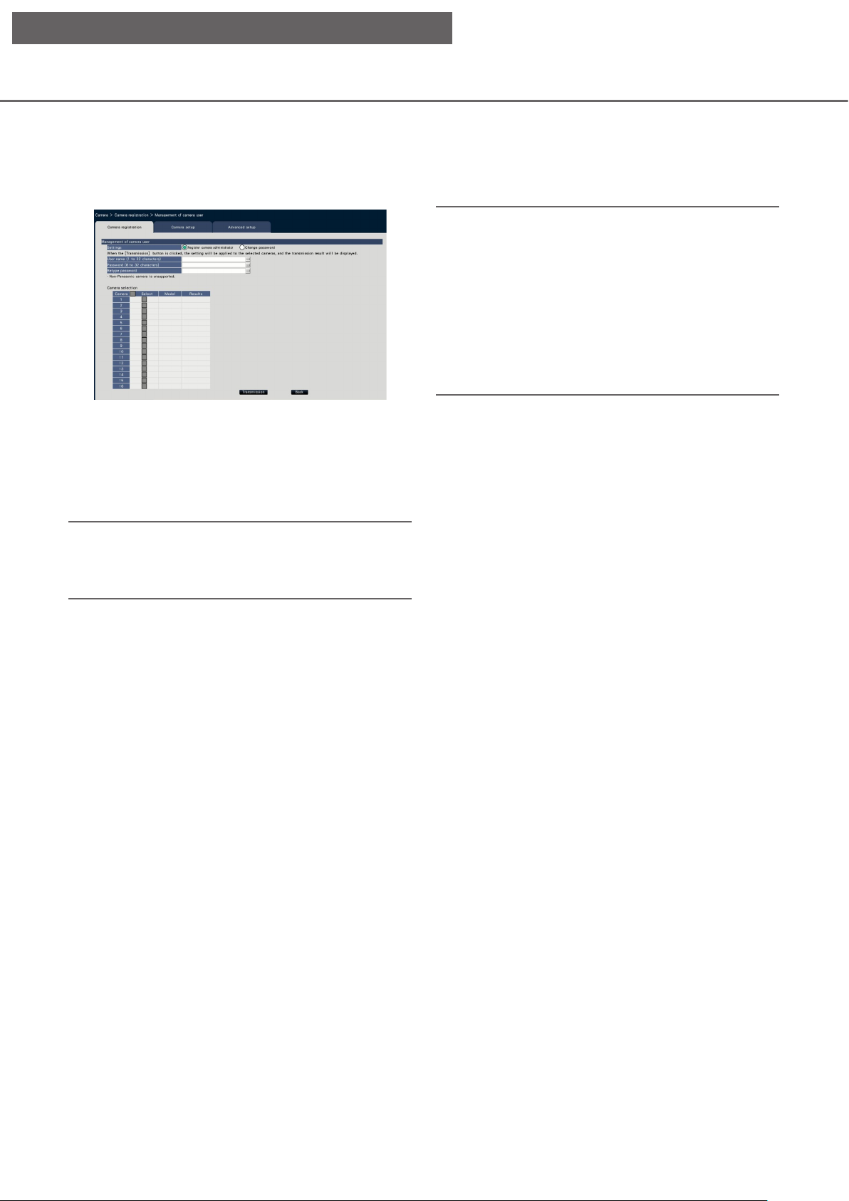
Change the password of camera [Management of camera user]
Click the [Setup >] button of "Management of camera user" on the [Camera registration] tab to display the
following screen.
[Settings]
Select items to set up.
Register camera administrator: Registers a user name
and password to a camera whose administrator is not
registered. Enter a user name/password.
Note:
• For user name and password, enter those of camera
administrator rights according to the specications
of the camera. (Please refer to the operating instructions of the camera.)
• The entered user name and password are set as
registered information of the applicable camera
when the settings to the camera is completed.
• Click [Exit] button when you set the user name
and password.
Note:
• Cameras that already have the User name/
Password registered cannot register another User
name/Password.
Change password: Changes the password of the
camera user registered to the recorder only. Enter a
password.
■ Camera selection
Select the camera to which the settings are sent.
Mark the checkbox of the camera to which the set
user name and password are sent.
(When "Register camera administrator" is selected in
the "Settings", you cannot select cameras whose
administrators have already been registered.)
[Transmission] button
Transmit the settings to the camera. Once transmission is completed and the setting has been applied to
the camera, "OK" will be displayed in the "Results"
eld. If the display reads "Authentication error", etc.,
the camera connection or the setting may have failed.
[Back] button
Click the button after completing the settings. The
screen returns to the [Camera registration] tab.
14
Page 15

[Setup via recorder's main monitor]
Change the registered information [Registered information]
Click the [Setup >] button for "Registered information" on the [Camera registration] tab to display the following
items.
After editing the settings, click the [OK] button to save the settings and return to the [Camera registration] tab.
[Camera]
Up to 32 cameras can be connected. By registering
the licenses, number of the cameras can be increased
to 24 or 32.
[Model]
The model of a registered camera will be displayed.
(Blank: Camera is not registered)
Click the [▼] button to select the camera model from
the camera categories. Refer to the "readme.txt" on
the provided CD-ROM for camera categories.
It is unnecessary to change it for normal use.
[Option]
Assign the operational mode of the camera having a
specic function due to the difference in function of
the camera.
Note:
• Assignment example by the application of camera
stream
①Recording by compression of H.264, 1-screen
live display, browser display: H. 264(1)
②Sub-stream recording by compression of
H.264, live multi-screen display: H.264(2)
③Recording by compression of H.264 or H.265,
1-screen live display, browser display:
H.264(1), H.264(3), H.264(4), H.265(1), H.265(3),
H.265(4)
④Sub-stream recording by compression of H.264
or H.265, live multi-screen display:
H.264(2), H.265(2)
• When selecting "MJPEG" for "Compression", the
live image transmission rate and the frame rate
will be changed automatically to "5 ips".
(☞ Page 35)
• When selecting "MJPEG" for "Compression",
images whose aspect ratio is 16:9 cannot be
selected. (☞ Page 38)
• When selecting "H.264(n)" or "H.265(n)" for
"Compression", it will become possible to select
"XF" in the image quality setting.
• Depending on the model of the camera, the camera may reboot when the compression method is
changed. The reboot will be detected as a communication error, but that is not a malfunction.
[Address]
An address already in use will be displayed. The
address can be changed using the on-screen keyboard. Enter up to 255 alphanumeric characters
including hyphens (-) and periods (.).
Note:
• Entering "http://" is not necessary if the host name
is entered.
[Compression]
Select the image compression method.
H.265(1)/ H.265(3)/ H.265(4)/ H.264(1)/ H.264(3)/
H.264(4)/ MJPEG
[User name]
Enter the user name for accessing the cameras and
logging in using the on-screen keyboard (☞ Installation
Guide Page 8). Register the user name whose
access level is "Administrator".
[Password]
Enter the password to be used for the user whose name
has been registered as "User name" (☞ Installation
Guide Page 8). (Up to 32 alphanumeric characters)
[Port No.]
Set a port number from 1 - 65535 for use by the camera.
Default: 80
Note:
• Enter the port number in ve digits, right aligned.
(Example: When the port number is 80, enter
"00080".) The leading zeros are omitted here.
15
Page 16

[Setup via recorder's main monitor]
[Table to delete]
To delete registration information or remove a previously connected camera, either select the camera
number and click the [Delete] button, or delete the IP
address of the respective camera.
[Auto model number acquisition]
Click the [Execute] button to acquire the model number from the camera registered for this product and
update the model number information.
When the acquired model number is different from
the registered one, as the image capture size is
changed to the default, reset the image capture size
in [REC & event]-[Recording setup] again.
Interchange camera numbers [Change the display position of camera]
Click the [Setup >] button for "Change the display position of camera" on the [Camera registration] tab to display the following items.
The registered camera is displayed on the screen from the left top to right in order of 1, 2, ∙∙∙16. If the conguration is set to 32 cameras, they are displayed on two 16-screen.
To interchange camera numbers, drag the camera image to be moved with the mouse and drop on the desired
position.
If the camera titles are to be interchanged as well, mark the "Also change camera titles" checkbox.
[Refresh] button
Obtain the latest camera image after interchanging
cameras.
[Back] button
Save the settings and return to the [Camera registration] tab.
16
Page 17
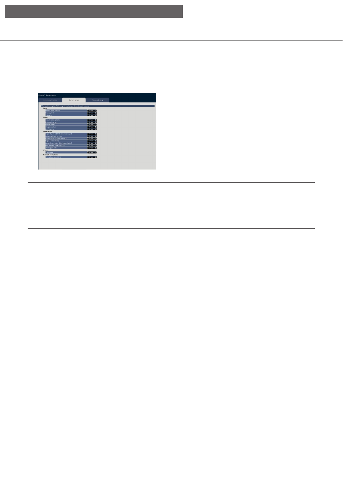
[Setup via recorder's main monitor]
[Camera setup] tab
Transmit the date & time and text displayed on an image, the refresh rate, the VMD alarm and the Light control
mode etc. settings to the camera. Click the [Setup >] button for each item to open the respective setup window.
Note:
• The settings of some models of Panasonic cameras only can be congured. Refer to the "readme.txt" on
the provided CD-ROM about the supported cameras. Some functions are not supported depending on the
models of the connected cameras. For further information about detailed specications, refer to the operating instructions of the cameras in use.
• It is impossible to check the current settings using this recorder.
17
Page 18
[Setup via recorder's main monitor]
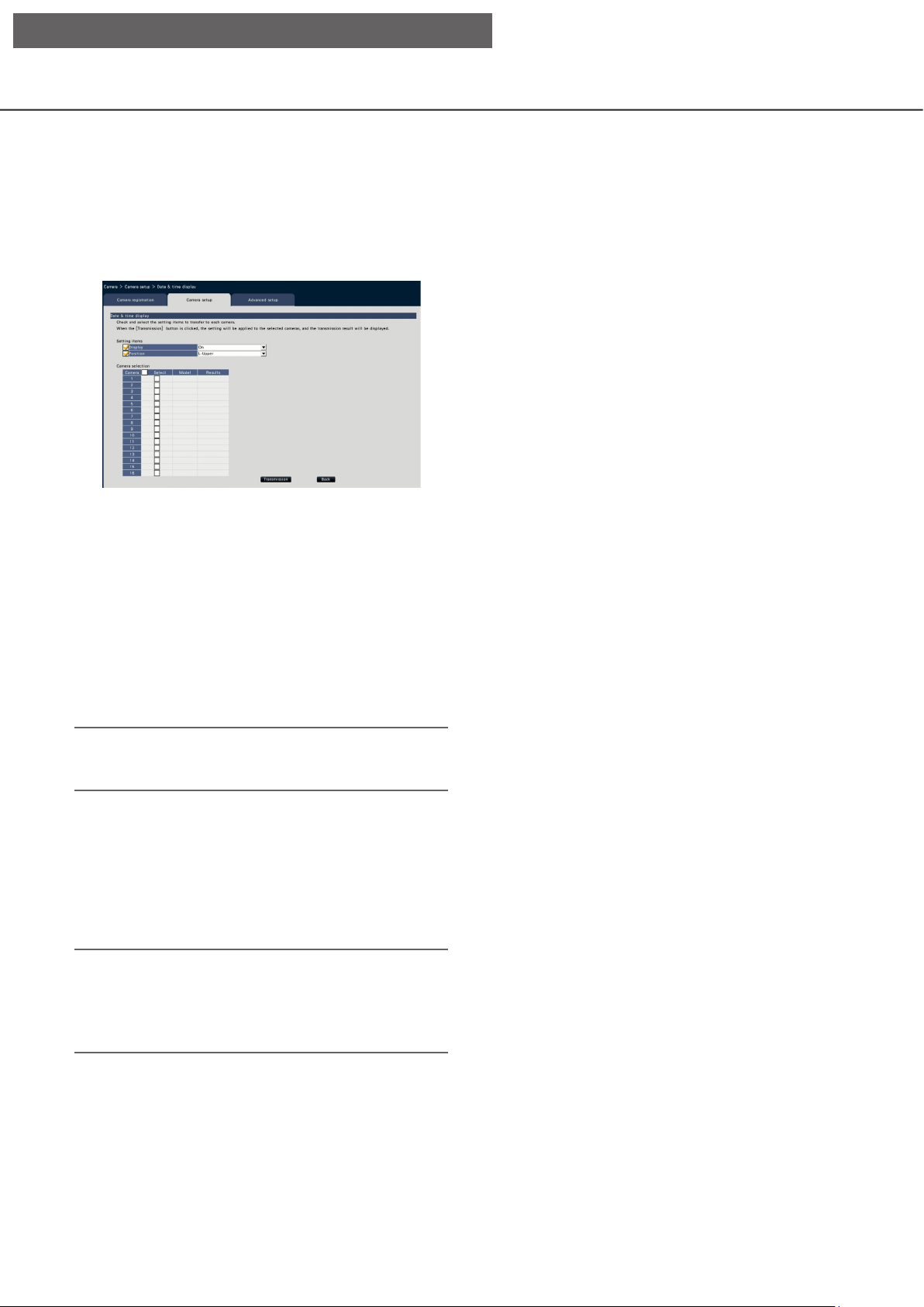
Set up date & time display [Date & time display]
Select the date & time display position for each camera and transmit it to the cameras to change the camera
settings.
Clicking the [Setup >] button for "Date & time display" on the [Camera setup] tab will display the following
items.
■ Camera selection
Select the camera to which the date & time display
setting is to be sent. Mark the checkbox of the camera to which the setup information is to be transmitted.
[Transmission] button
Transmit the date & time setting to the camera.
Once transmission is completed and the setting has
been applied to the camera, "OK" will be displayed in
the "Results" eld. If the display reads "Authentica-
■ Setting items
[Display]
Choose whether or not to display the date & time. If
date & time display is activated, date & time will be
displayed on camera images and will also be
recorded with the recorded images.
To transmit the settings to the camera, mark this
item, and select either of the following.
On: Date & time displayed
Off: Date & time not displayed
tion error", etc., the camera connection or the setting
may have failed.
[Back] button
Click the button after completing the settings. The
screen returns to the [Camera setup] tab.
Note:
• The display format corresponds to the settings on
the [Date & time settings] tab (☞ Page 10).
[Position]
Select the position to display the date & time on the
images.
If the setting is to be transmitted to the camera, mark
this item to select the display position.
L-Upper/ L-Lower/ R-Upper/ R-Lower
Note:
• The position to display the title edited on "Display
Title" (☞ Page 19) is the same as the "Position"
selected here to display the date & time edited on
"Date & time display".
18
Page 19
[Setup via recorder's main monitor]
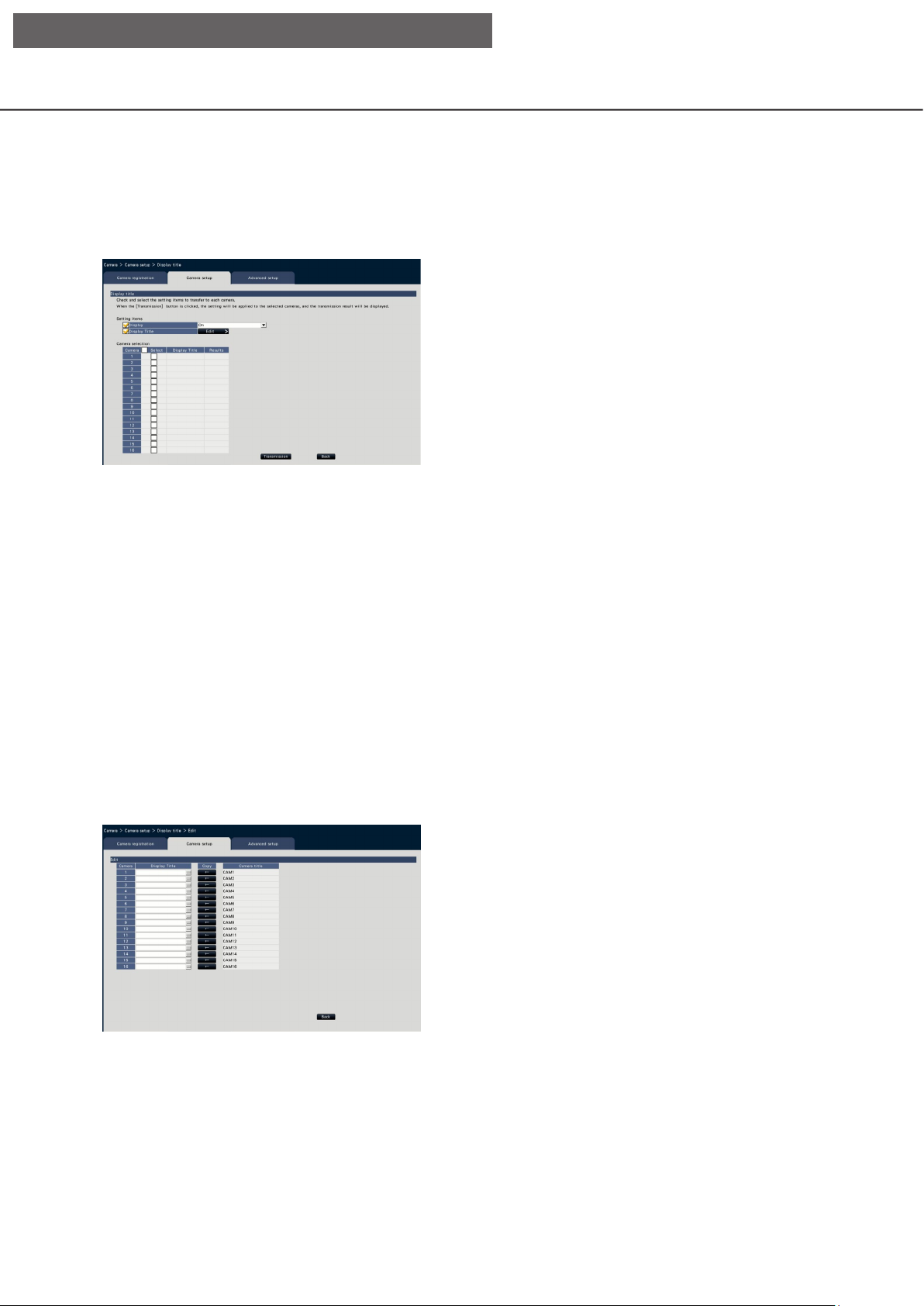
Set up OSD [Display Title]
Determine whether to display the title and select the title to display for each camera, the settings will be
changed after the settings have been transmitted to the camera.
Clicking the [Setup >] button for "Display Title" on the [Camera setup] tab will display the following items.
Enter a character string to be displayed on the
Available characters: 0-9, A-Z, ! # $ % ( )* + , - . / :
Display the camera title registered on the [Main
■ Setting items
[Display]
Select whether or not to display the title on camera
images. If title display is activated, the title will be displayed on camera images and will also be recorded
with the recorded images.
To transmit the settings to the camera, mark this
item, and select either of the following.
On: Title displayed
Off: Title not displayed
The camera title registered on the [Main monitor]
Click the button after completing the settings.
• [Display Title]
image using the on-screen keyboard. (☞ Installation Guide Page 8) (Up to 16 alphanumeric characters)
; = ?
• [Camera title]
monitor] tab of the monitor page (☞ Page 46).
• [Copy] button
tab of the monitor page can be used as display
title. Clicking this button will copy the camera title
to the "Display Title" eld.
• [Back] button
This will close the window.
[Display Title]
To transmit the settings to the camera, mark this
item, and edit the title displayed on the image. Clicking the [Edit >] button will display the following title
editing window:
■ Camera Selection
Select the camera to which the setting of the "Display
title" is to be sent.
Mark the checkbox of the camera to which the setup
information is to be transmitted.
[Transmission] button
Transmit the setting of the "Display title" to the camera.
Once transmission is completed and the setting has
been applied to the camera, "OK" will be displayed in
the "Results" eld.
If the display reads "Authentication error", etc., the
camera connection or the setting may have failed.
[Back] button
Click the button after completing the settings.
The screen returns to the [Camera setup] tab.
19
Page 20

[Setup via recorder's main monitor]
Set up how to turn on or off the indicators [Indicator]
Select how to turn on or off the link indicator, access indicator or status indicators for each camera and transmit the information to the cameras to change the camera settings. Refer to the operating instructions of the
camera for further information.
Clicking the [Setup >] button for "Indicator" on the [Camera setup] tab will display the setup page.
[Indicator]
On: All the indicators will light in accordance with
the status.
On (Access): Only the live indicator will light when
images are viewed.
Off: All the indicators will light off.
■ Camera Selection
Select the camera to which the "Indicator" setting is
to be sent.
Mark the checkbox of the camera to which the setup
information is to be transmitted.
[Transmission] button
Transmit the setting of the "Indicator" to the camera.
Once transmission is completed and the setting has
been applied to the camera, "OK" will be displayed in
the "Results" eld.
If the display reads "Authentication error", etc., the
camera connection or the setting may have failed.
[Back] button
Click the button after completing the settings.
The screen returns to the [Camera setup] tab.
20
Page 21

[Setup via recorder's main monitor]
Set the camera image transmission priority [Transmission priority]
Select the transmission priority setting for each camera and transmit the information to the cameras to change
the camera settings.
Clicking the [Setup >] button for "Transmission priority" on the [Camera setup] tab will display the setup page.
[Control time period]
Select the period of controlling H.264 bit rate to be
recorded from the following when the transmission
priority is "Advanced VBR".
[Priority setting]
Set which to prioritize, the "Frame rate" or the "Image
quality", when the transmission priority is the "Frame
rate".
■ Setting items
[Transmission priority]
Select the transmission mode for H.264/H.265 images
from the following.
The "Transmission priority" will be congured based
on the markings of the checkboxes of "Stream1" and
"Stream2".
Frame rate: H.264/H.265 images will be transmitted
with the frame rate specied in "Frame rate".
Advanced VBR: H.264 images will be transmitted
with the frame rate specied in "Frame rate".
When this parameter is selected, this product
transmits images while adjusting the average
of transmission amount in the period specied
in "Control time period" to match it to the
specied bit rate.
VBR: Transmits H.264/H.265 images with the
frame rate specied in "Frame rate" and the
image quality level specied in "Image quality"
kept. The image quality is xed and the storage capacity varies according to the "Image
quality" setting and conditions of the object.
Note:
• Set up the transmission mode again when the
camera is changed on the camera registration
screen or change of the camera is detected.
[Smart coding (GOP control)]
Set whether to use the GOP control or not when the
transmission priority is set to the "VBR".
■ Camera Selection
Select the camera to which the setting of the "Transmission priority" is to be sent.
Mark the checkbox of the camera to which the setup
information is to be transmitted.
[Transmission] button
Transmit the setting of the "Transmission priority" to
the camera.
Once transmission is completed and the setting has
been applied to the camera, "OK" will be displayed in
the "Results" eld.
If the display reads "Authentication error", etc., the
camera connection or the setting may have failed.
1 h, 6 h, 24 h, 1 week
Frame rate priority: Prioritizes the frame rate. The
image quality may vary according to the
object.
Image quality priority: Reduces the change in the
image quality. The frame rate may be slower
depending on the object.
Off: Does not use the GOP control.
On (Advanced): Can reduce the data amount
when the motion in the image is less.
[Burst tolerance level]
Select the allowance of "Max bit rate (per client)" for
the H.264 bit rate from the following when the transmission priority is "Advanced VBR".
High, Middle, Low
[Back] button
Click the button after completing the settings.
The screen returns to the [Camera setup] tab.
21
Page 22
[Setup via recorder's main monitor]
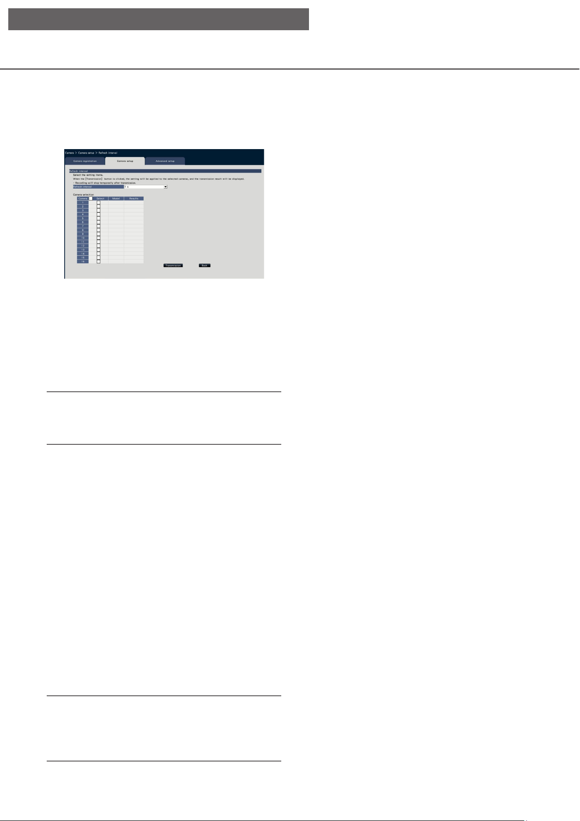
Set up the refresh interval [Refresh interval]
Select the image refresh interval for each camera and transmit it to the cameras to change the camera settings.
Clicking the [Setup >] button for "Refresh interval" on the [Camera setup] tab will display the setup page.
[Refresh interval]
Select an interval to update the image display. If used
in a network environment where frequent errors
occur, shorten the refresh interval to reduce image
distortions. However, the refresh interval may be
longer than the set value.
0.2 s/ 0.5 s/ 1 s/ 2 s/ 3 s
Note:
• Set up the refresh interval again when the camera
is changed on the camera registration screen or
change of the camera is detected.
■ Camera Selection
Select the camera to which the setting of the "Refresh
interval" is to be sent.
Mark the checkbox of the camera to which the setup
information is to be transmitted.
[Transmission] button
Transmit the setting of the "Refresh interval" to the
camera.
Once transmission is completed and the setting has
been applied to the camera, "OK" will be displayed in
the "Results" eld.
If the display reads "Authentication error", etc., the
camera connection or the setting may have failed.
[Back] button
Click the button after completing the settings.
The screen returns to the [Camera setup] tab.
Important:
• Image transmission from the camera will temporarily be canceled and no image will be recorded
during this period if the setting to change the
refresh interval is transmitted to the camera.
22
Page 23

[Setup via recorder's main monitor]
Set up the method of camera installation [Upside-down]
Select the method of installation for each camera and transmit the information to the cameras to change the
camera settings.
Clicking the [Setup >] button for "Upside-down" on the [Camera setup] tab will display the setup window.
[Upside-down]
On (desktop): Select this when the camera is to
be installed with the dome side up.
Off (ceiling): Select this when the camera is to be
installed with the dome side down.
Wall: Select this when the camera is to be
installed on a wall.
■ Camera Selection
Select the camera to which the setting of the
"Upside-down" is to be sent.
Mark the checkbox of the camera to which the setup
information is to be transmitted.
[Transmission] button
Transmit the setting of the "Upside-down" to the
camera.
Once transmission is completed and the setting has
been applied to the camera, "OK" will be displayed in
the "Results" eld.
If the display reads "Authentication error", etc., the
camera connection or the setting may have failed.
[Back] button
Click the button after completing the settings.
The screen returns to the [Camera setup] tab.
Note:
• If a sheye camera is registered, "Off (ceiling)" will
be set. Select "Wall" to install the camera on the
wall.
23
Page 24

[Setup via recorder's main monitor]
Set the image rotation of camera [Image rotation]
Select the image rotation for each camera and transmit it to the camera to change the camera settings.
Clicking the [Setup >] button for "Image rotation" on the [Camera setup] tab will display the setup window.
[Image rotation]
• 0 °(Off): Does not rotate the image.
• 90 °: Rotates the image by 90 °.
• 180 °(Upside-down): Inverses the image upside-down.
• 270 °: Rotates the image by 270 °.
■ Camera Selection
Select the camera to which the setting of the "Image
rotation" is to be sent. Mark the checkbox of the
camera to which the setup information is to be
transmitted.
[Transmission] button
Transmit the setting of the "Image rotation" to the
camera.
Once transmission is completed and the setting has
been applied to the camera, "OK" will be displayed in
the "Results" eld.
If the display reads "Authentication error", etc., the
camera connection or the setting may have failed.
[Back] button
Click the button after completing the settings.
The screen returns to the [Camera setup] tab.
24
Page 25

[Setup via recorder's main monitor]
Set up pan/tilt-flip [Pan/tilt-flip]
Select the pan/tilt-ip function for each camera and transmit the information to the cameras to change the camera settings.
Clicking the [Setup >] button for "Pan/tilt-ip" on the [Camera setup] tab will display the setup page.
[Pan/tilt-flip]
Select whether or not to activate the pan/tilt-ip function that can achieve camera controllability equal to
360° endless cameras.
On: The pan/tilt-ip function will work.
Off: The pan/tilt-ip function will not work.
■ Camera Selection
Select the camera to which the setting of the "Pan/
tilt-ip" is to be sent.
Mark the checkbox of the camera to which the setup
information is to be transmitted.
[Transmission] button
Transmit the setting of the "Pan/tilt-ip" to the camera.
Once transmission is completed and the setting has
been applied to the camera, "OK" will be displayed in
the "Results" eld.
If the display reads "Authentication error", etc., the
camera connection or the setting may have failed.
[Back] button
Click the button after completing the settings.
The screen returns to the [Camera setup] tab.
25
Page 26

[Setup via recorder's main monitor]
Set up Super Dynamic [Super Dynamic (Wide dynamic range)]
Select the Super Dynamic function for each camera and transmit the information to the cameras to change the
camera settings.
Clicking the [Setup >] button for "Super Dynamic (Wide dynamic range)" on the [Camera setup] tab will display
the setup page.
[Super Dynamic (Wide dynamic range)]
Select "On" or "Off" to determine whether or not to
activate the super dynamic function.
On (High): The super dynamic function will work.
When "On (High)" is selected, the tone level
will be compensated to emphasize the contrast.
On: The super dynamic function will work. When
"On" is selected, the tone level will be compensated to emphasize the sensitivity.
Off: The super dynamic function will not work.
■ Camera Selection
Select the camera to which the setting of the "Super
Dynamic" is to be sent.
Mark the checkbox of the camera to which the setup
information is to be transmitted.
[Transmission] button
Transmit the setting of the "Super Dynamic" to the
camera.
Once transmission is completed and the setting has
been applied to the camera, "OK" will be displayed in
the "Results" eld.
If the display reads "Authentication error", etc., the
camera connection or the setting may have failed.
[Back] button
Click the button after completing the settings.
The screen returns to the [Camera setup] tab.
26
Page 27

[Setup via recorder's main monitor]
Set the adaptive black stretch function of the camera [Adaptive black stretch]
Determine whether to enable the adaptive black stretch function for each camera. The settings will be changed
after the settings have been transmitted to the camera.
Clicking the [Setup >] button for "Adaptive black stretch" on the [Camera setup] tab will display the setup window.
[Adaptive black stretch]
By using the adaptive black stretch function, dark
area in the image will turn brighter by the digital
image processing.
On: The adaptive black stretch function will be
enabled.
Off: The adaptive black stretch function will be
disabled.
■ Camera Selection
Select the camera to which the setting of the "Adaptive black stretch" is to be sent.
Mark the checkbox of the camera to which the setup
information is to be transmitted.
[Transmission] button
Transmit the setting of the "Adaptive black stretch" to
the camera.
Once transmission is completed and the setting has
been applied to the camera, "OK" will be displayed in
the "Results" eld.
If the display reads "Authentication error", etc., the
camera connection or the setting may have failed.
[Back] button
Click the button after completing the settings.
The screen returns to the [Camera setup] tab.
Important:
• When "On" is selected for "Adaptive black
stretch", noise in dark area in image may increase
and the periphery of the border between the dark
area and the bright area will be displayed brighter/
darker than the other brighter/darker area in the
image.
27
Page 28

[Setup via recorder's main monitor]
Set the back light compensation function of the camera [Back light compensation
(BLC)]
Determine whether to enable the back light compensation function for each camera. The settings will be
changed after the settings have been transmitted to the camera.
Clicking the [Setup >] button for "Back light compensation (BLC)" on the [Camera setup] tab will display the
setup window.
[Back light compensation (BLC)]
When "On" is selected for "Super Dynamic", this
function is not available.
The back light compensation function masks the
brighter area in image and compensates exposure in
silhouette created by back light.
On: Mask area will automatically be set.
Off: Mask area will not be set automatically. It is
necessary to set mask areas manually.
■ Camera Selection
Select the camera to which the setting of the "Back
light compensation (BLC)" is to be sent.
Mark the checkbox of the camera to which the setup
information is to be transmitted.
[Transmission] button
Transmit the setting of the "Back light compensation
(BLC)" to the camera.
Once transmission is completed and the setting has
been applied to the camera, "OK" will be displayed in
the "Results" eld.
If the display reads "Authentication error", etc., the
camera connection or the setting may have failed.
[Back] button
Click the button after completing the settings.
The screen returns to the [Camera setup] tab.
28
Page 29

[Setup via recorder's main monitor]
Set up Light control mode [Light control mode]
Select how to control the amount of light for each camera and transmit the information to the cameras to
change the camera settings.
Clicking the [Setup >] button for "Light control mode" on the [Camera setup] tab will display the setup page.
[Light control mode]
Outdoor scene: Depending on the brightness
level (illuminance), the iris will automatically be
controlled together with the shutter speed
adjustment to control light.
Indoor scene (50Hz): The shutter speed will auto-
matically be adjusted to prevent icker caused
by uorescent light. (For the 50 Hz areas)
Indoor scene (60Hz): Same as "Indoor scene"
above. (For 60 Hz areas)
ELC: The iris will automatically be controlled with
the shutter speed adjustment to control light.
■ Camera Selection
Select the camera to which the setting of the "Light
control mode" is to be sent.
Mark the checkbox of the camera to which the setup
information is to be transmitted.
[Transmission] button
Transmit the setting of the "Light control mode" to
the camera.
Once transmission is completed and the setting has
been applied to the camera, "OK" will be displayed in
the "Results" eld.
If the display reads "Authentication error", etc., the
camera connection or the setting may have failed.
[Back] button
Click the button after completing the settings.
The screen returns to the [Camera setup] tab.
Note:
• When "Outdoor scene" is selected, icker may
occur when a subject is under uorescent lighting.
29
Page 30

[Setup via recorder's main monitor]
Set the automatic slow shutter of the camera [Auto slow shutter (Maximum
shutter)]
Select the auto slow shutter setting for each camera and transmit the information to the cameras to change the
camera settings.
Clicking the [Setup >] button for "Auto slow shutter (Maximum shutter)" on the [Camera setup] tab will display
the setup page.
Note:
• When "Max. 16/30s" is selected, the electronic
sensitivity will automatically be enhanced up to 16
times.
• When "Off" is selected for "AGC", this function is
not available. Refer to the operating instructions
of the camera for further information.
[Auto slow shutter (Maximum shutter)]
The auto slow shutter adjusts the sensor storage time
to enhance the electronic sensitivity.
The following are available setting values.
Off (1/30s)/ Max. 2/30s/ Max. 4/30s/ Max. 6/30s/
Max. 10/30s/ Max. 16/30s
■ Camera Selection
Select the camera to which the setting of the "Auto
slow shutter" is to be sent.
Mark the checkbox of the camera to which the setup
information is to be transmitted.
[Transmission] button
Transmit the setting of the "Auto slow shutter" to the
camera.
Once transmission is completed and the setting has
been applied to the camera, "OK" will be displayed in
the "Results" eld.
If the display reads "Authentication error", etc., the
camera connection or the setting may have failed.
[Back] button
Click the button after completing the settings.
The screen returns to the [Camera setup] tab.
Important:
• When the auto slow shutter is set, the frame rate
may drop. Noise or white dots (scratches) may
also be seen in image.
30
Page 31

[Setup via recorder's main monitor]
Set the black and white switchover of the camera [Day & Night (IR/electrical)]
Select the day and night setting for each camera and transmit the information to the cameras to change the
camera settings.
Clicking the [Setup >] button for "Day & Night (IR/electrical)" on the [Camera setup] tab will display the setup
window.
■ Camera Selection
Select the camera to which the setting of the "Day &
Night (IR/electrical)" is to be sent.
Mark the checkbox of the camera to which the setup
information is to be transmitted.
[Transmission] button
Transmit the setting of the "Day & Night (IR/electrical)"
to the camera.
Once transmission is completed and the setting has
been applied to the camera, "OK" will be displayed in
[Day & Night (IR/electrical)]
Select a method of how to switch between B/W
image and color image from the following.
Off: Color images will always be taken.
On: B/W images will always be taken.
On (IR Light On): B/W images will always be
taken. Use it at night time or using near-IR
lighting.
Auto1 (Normal)/Auto: Depending on the image
brightness (illuminance), the system automatically switches from/ to the color image to/from
B/W image.
It switches to the color mode when the light
source is bright and to the monochrome mode
when the light source is not bright.
Auto2 (IR Light): Use it at night time or when using
near-IR light source.
Auto3 (Super Chroma Compensation (SCC)): Use
it if you want to keep the color image even if
the light source is not bright. Super Chroma
Compensation (SCC) function keeps the color
image under the lower illuminance than "Auto1
(Normal)".
the "Results" eld.
If the display reads "Authentication error", etc., the
camera connection or the setting may have failed.
[Back] button
Click the button after completing the settings.
The screen returns to the [Camera setup] tab.
Note:
• "On", "Auto2" and "Auto3" can be selected for
cameras having "Day & Night (electrical)" only, but
they are not operable.
31
Page 32

[Setup via recorder's main monitor]
Set the intelligent auto of camera [Intelligent auto]
Select the intelligent auto for each camera and transmit it to the camera to change the camera settings.
Clicking the [Setup >] button for "Intelligent auto" on the [Camera setup] tab will display the setup window.
[Intelligent auto]
Set whether or not to turn on the intelligent auto function. The intelligent auto is a function to judge the
scene (back light, outside, night view), people's faces,
objects in motion, stop the lens down automatically
and adjust the shutter speed and contrast to improve
visibility of people's faces and objects in motion.
Off: Does not use the intelligent auto function
On: Uses the intelligent auto function
■ Camera Selection
Select the camera to which the setting of the
"Intelligent auto" is to be sent. Mark the checkbox of
the camera to which the setup information is to be
transmitted.
[Transmission] button
Transmit the setting of the "Intelligent auto" to the
camera.
Once transmission is completed and the setting has
been applied to the camera, "OK" will be displayed in
the "Results" eld.
If the display reads "Authentication error", etc., the
camera connection or the setting may have failed.
[Back] button
Click the button after completing the settings.
The screen returns to the [Camera setup] tab.
32
Page 33

[Setup via recorder's main monitor]
Set up VMD alarm [VMD alarm]
Select the VMD function for each camera and transmit the information to the cameras to change the camera
settings.
Clicking the [Setup >] button for "VMD alarm" on the [Camera setup] tab will display the setup page.
[VMD alarm]
Select whether or not to use the VMD (VMD: Video
Motion Detection) alarm function when a change
(movement) is detected in the image. Refer to the
operating instructions of the camera in use for how to
congure the VMD alarm.
On: Detects alarms.
Off: Does not detect alarms.
[Detection sensitivity]
To transmit the settings to the camera, mark this item,
and select either of the following.
1(Low) - 15(High)
■ Camera Selection
Select the camera to which the setting of the "VMD
alarm" is to be sent. Mark the checkbox of the camera
to which the setup information is to be transmitted.
[Transmission] button
Transmit the setting of the "VMD alarm" to the camera.
Once transmission is completed and the setting has
been applied to the camera, "OK" will be displayed in
the "Results" eld. If the display reads "Authentication error", etc., the camera connection or the setting
may have failed.
[Back] button
Click the button after completing the settings.
The screen returns to the [Camera setup] tab.
33
Page 34

[Setup via recorder's main monitor]
[Advanced setup] tab
Set the connection method of the camera.
Clicking the [Setup >] button of "Connection method" under the [Advanced setup] tab displays the setup screen.
■ Connection method
[Connection method]
Set the connection method for each camera.
RTP: Connects with the RTP.
RTSP: Connects with the RTSP. It is used for
local camera connection and others.
Internet mode: Connects in the Internet mode. It
is used to connect remote cameras or for
other connection.
Note:
• The connection method will become valid for the
Panasonic camera whose compression type is
H.264/H.265.
34
Page 35

[Setup via recorder's main monitor]
Set up recording/events [REC & event]
The "REC & event" page has 3 tabs; the [Recording setup] tab, the [Event setup] tab and the [Advanced setup] tab.
Recording setup tab [Recording setup]
Congure the settings relating to schedule recording. Set the day(s), time table(s), frame rate and image quality
for recording.
[Schedule recording]
Mark the checkbox (es) if you want to carry out the
schedule recording based on the set time bar.
[Event recording]
Mark the checkbox (es) if you want to carry out event
recording based on the set time bar. The recorder
does not record the image even if the alarm occurs
during time in which the event recording is not set.
■ Schedules
Recording will be performed according to the schedules set in advance. Select the day(s) of the week and
the time table(s).
[Days to record]
Select the day(s) of the week to record. Mark the
checkbox(es) of the day(s) of the week to record.
[Schedule to record]
6 time tables can be set up for "[Time table1]". The
time bar indicates 24 hours in steps of 15 minutes.
Click the desired position on the time bar to designate the start and end time. When the time is designated, the time bar turns red.
Note:
• At the default, schedule recording and event
recording have been set for 24 hours on Time
table1. To delete the designated start and end
time, right-click the timetable.
• The recording time table can be set by dragging the
start and end time on the time bar with the mouse.
• Be sure to set so that there is no overlap between
the 6 time tables. When attempting to set the
same time as already set on another time bar, the
time immediately before or after the overlapping
time will be set.
• Within the same time table, event recording has
priority over schedule recording.
[e-Mail]
To send an alarm e-mail when an event occurs, mark
this item. The event recording must be checked to set
this item.
Refer to "Congure the settings relating to the mail
notication [e-Mail]" (☞ Page 54) for the setting of
the destination.
[Panasonic alarm protocol]
Mark the checkbox of this item to automatically transmit information on an event that occurs to a PC using
the Panasonic alarm protocol. The event recording
must be checked to set this item.
Refer to "Congure the Panasonic alarm protocol
settings [Panasonic alarm protocol]" (☞ Page 55)
for the setting of the address.
[Advanced >] button
The "Advanced schedule setup" page will be displayed. In addition to 6 schedule recordings, 6 event
recordings can be set up. The schedule settings can
be set up to 16 patterns. (☞ Page 36)
■ Recording setup (All cameras)
Set the recording frame rate and image quality. The
settings will be applied to all cameras.
[Frame rate]
Select the recording frame rate.
1 ips/ 3 ips/ 5 ips/ 10 ips/ 15 ips/ 30 ips
Default: 10 ips
35
Page 36

[Setup via recorder's main monitor]
Important:
• For a camera whose compression method is [MJPEG],
"10 ips / 15 ips / 30 ips" cannot be selected.
• If a camera whose compression method is
[MJPEG] is included, [MJPEG] camera is set to
"5 ips" even if "10 ips / 15 ips / 30 ips" is set by
slider bar of frame rate setting. You can conrm
the current setting value with [Advanced setup >]
in Recording setup (All cameras).
[Image quality]
Select the recording image quality.
NQ (Normal): Standard quality
FQ (Fine): High quality
SF (Super Fine): Super ne quality
XF (Extra Fine): Extra ne quality
Default: FQ
Important:
• For a camera whose compression method is
[MJPEG], "XF" cannot be set.
• If a camera whose compression method is [MJPEG]
is included, [MJPEG] camera is set to "SF" even if
"XF" is set by slider bar of image quality setting. You
can conrm the current setting value with [Advanced
setup >] in Recording setup (All cameras).
[Referenced recording days]
Calculates and displays the total number of days for
which recording on the hard disk drives is available.
Note:
• The referenced recording days will be displayed correctly only when the settings have been saved while
the recorder has recognized the camera correctly.
• The referenced recording days will be calculated
based on the assumption that recording is started
on Monday. The special day settings are not taken
into account.
• This value excludes the HDD consumption for the
event/emergency recording.
• If a camera manufactured by other than
Panasonic is used, the value of "Referenced
recording days" will not be displayed.
• "*" preceding an item indicates that the item has
been changed on the "Advanced recording setup"
page.
• When congured to perform recording in high resolution and high quality, recording may sometimes
not be performed at the specied rate. When
there may be possibility to fail recording at the
specied rate while using only Panasonic cameras, the conrmation window will be displayed.
[Advanced >] button
The "Advanced recording setup" will be displayed.
Each camera can be set up separately for recording.
(☞ Page 37)
Configure the advanced settings for schedule recording
[Advanced schedule setup]
Up to 16 schedule patterns can be set. Up to 6 time zones of the schedule recording or event recording can be
set for each schedule.
Clicking the [Advanced >] button in the "Schedules" eld will open the "Advanced schedule setup" page.
Time table1: Recording according to Time table1.
Time table2: Recording according to Time table2.
Off: Neither schedule nor event recording will take
place.
■ Event recording
Set the recording duration in the event that an alarm
occurs and the recording duration before an alarm
occurs.
[Event recording duration]
■ Days to record
Select the actions to be taken on each day of the
week based on a time table. [●] indicates the
selected state, [○] the unselected state.
Set the recording duration in the event that an alarm
occurs.
2 s/ 5 s/ 10 s/ 20 s/ 30 s/ 1 min/ 2 min/ 3 min/
5 min/ 10 min/ 15 min
36
Page 37

[Setup via recorder's main monitor]
Manual: Recording will continue while receiving
an alarm input signal. Recording will be performed for at least 8 seconds.
Ext.: Alarm output will continue until the alarm
action is reset. Refer to the "Cancel the alarm
action" (☞ Page 126) for further information
about how to cancel the alarm action.
Default: 30 s
[Pre-event duration]
Set the recording duration before an alarm occurs.
0 s/ 5 s/ 10 s/ 15 s
Default: 0 s
Note:
• The actual recording time may sometimes be
longer than the duration selected for this setting.
• A 15 second pre-event recording is available when
the bit rate setting of the camera is 4Mbps. Time of
the pre-event recording may be shorter than the set
time if the image is recorded in high resolution over
4Mbps, high image quality and high rate.
• Pre-event recording is not performed when "0 s"
is selected.
• When images are set to be recorded together with
audio, the audio may not be recorded at the
beginning of the pre-event recording.
[Event recording] (☞ Page 35)
[e-Mail] (☞ Page 35)
[Panasonic alarm protocol] (☞ Page 35)
[Prev page] / [Next page]
The schedule settings to be congured will be
switched over.
[Display the schedule list.]
Display each time table from Schedule 1 to Schedule
16 and settings of the schedule recording, event
recording, etc. The schedule list will be displayed
when clicking [View] button.
Time zones from 1 to 6 of each time table are superimposed and displayed.
■ Schedule to record
Two time tables can be set.
[Schedule recording] (☞ Page 35)
[Back] button
Click the button after completing the settings. The
screen returns to the [Recording setup] tab.
Set up recording for individual cameras [Advanced recording setup]
Set up items such as the image capture size, frame rate and image quality for individual cameras.
Clicking the [Advanced >] button on the [Recording setup (All cameras)] tab will open the advanced setup page.
[Model]
The model number of the connected camera will be
displayed.
(Blank: Camera is not registered)
[Compression]
The compression method selected when registering
camera will be displayed.
[Image capture size]
Select a resolution for images to be recorded.
<When the aspect ratio is 4:3>
VGA(640×480)/ SVGA(800×600)/
SXVGA(1280×960)/ UXGA(1600×1200)/
QXGA(2048×1536)/ 5M(2560×1920)/
12M(4000×3000)
37
Page 38

[Setup via recorder's main monitor]
<When the aspect ratio is 16:9>
HVGAW(640×360)/ HD(1280×720)/
FHD(1920×1080)/ WQHD(2560×1440)/
4KUHD(3840×2160)
<When the aspect ratio is 1:1>
1.6M(1280×1280)/ 4M(2048×2048)/
5M(2192×2192)/ 8M(2816×2816)/ 9M(2992×2992)
<When the aspect ratio is 9:16>
0.2M(360×640)/ 1M(720×1280)/ 2M(1080×1920)
When the aspect ratio is set to 9:16, the image is
rotated by 90 °. If you want to rotate the image by
270 °, select 270 ° at "Set the image rotation of
camera [Image rotation]". (☞ Page 24)
Important:
• The available image capture sizes may differ
depending on the model of the camera and the
compression method.
Note:
• When congured to perform recording in high resolution and high quality, recording may sometimes
not be performed at the specied rate.
• Depending on the model of the camera, the camera may reboot when the image capture size is
changed. The reboot will be detected as a communication error, but that is not a malfunction.
[Rate] (Frame rate) (☞ Page 35)
Note:
• The 25 ips/ 50 ips/ 60 ips is available depending
on the camera model and settings of compression
and image capture size.
• The images of "60 ips (50 ips)" can be displayed
in one screen if a monitor compatible with
1920×1080 p/ 60 Hz (1920×1080 p/ 50 Hz) is used
as a main monitor. (The images on the main monitor other than 1-screen and on the sub monitor
are displayed in "30 ips (25 ips)".)
[Quality] (Image quality) (☞ Page 36)
[Audio]
Select whether or not to record audio together with
images.
On(AAC-LC): Audio will be recorded. (AAC-LC
format)
On: Audio will be recorded. (G.726 format)
Off: Audio will not be recorded.
Default: Off
[Schedule]
Select a schedule in which the desired recording to
be performed is included.
Schedule1 : Recording will be performed accord-
∙∙∙
Schedule16: Recording will be performed accord-
Default: Schedule1
[Event]
Select the frame rate of the event recording.
1 ips/ 3 ips/ 5 ips/ 10 ips/ 15 ips/ 25 ips/ 30 ips/
(Same as the basic)
Default: Same as the basic
[Emergency]
Set the frame rate of the emergency recording.
1 ips/ 3 ips/ 5 ips/ 10 ips/ 15 ips/ 25 ips/ 30 ips/
(Same as the basic)
Default: Same as the basic
Note:
• If the rate of the basic settings is 50 ips or 60 ips, the
settings of the event recording and the emergency
recording will be the same as the rate or the basic
setting and displayed as "Same as the basic". In this
case, the settings of the event recording and
emergency recording cannot be changed.
• The rates of recorded images set to 5 ips/ 10 ips/
15 ips become 4.2 ips/ 8.3 ips/ 12.5 ips
respectively if any of the basic setup, the event
recording or the emergency recording of the same
camera is set to 25 ips.
• If the SD backup rec. or the SD recording function
of the camera is used, set the frame rate of the
event recording and the emergency recording to
"Same as the basic".
[Referenced recording days] (☞ Page 36)
[Back] button
Click the button after completing the settings. The
screen returns to the [Recording setup] tab.
ing to the settings for schedule1.
ing to the settings for schedule16.
38
Page 39

[Setup via recorder's main monitor]
Configure event-related settings [Event setup] tab
Congure event-related settings such as the alarm output duration and buzzer duration.
[Message display]
Select whether or not to display a message on a PC
connected to a network when an alarm occurs.
Default: On
■ Alarm action
Congure alarm-related items such as alarm output
duration and alarm auto reset.
[Output duration]
Select the output duration for the alarm signal output
from the terminal on the recorder’s rear panel when
an alarm occurs. When "0 s" is selected, alarm signals will not be output.
0 s/ 2 s/ 5 s/ 10 s/ 20 s/ 30 s/ 1 min
Ext.: Alarm output will continue until the alarm
action is reset. Refer to the "Cancel the alarm
action" (☞ Page 126) for further information
about how to cancel the alarm action.
Rec.: Output of the alarm signal will continue dur-
ing event recording.
Default: 2 s
[Buzzer duration]
Set the duration of the buzzer sound when an alarm
occurs. When "0 s" is selected, the buzzer will not
sound.
0 s/ 2 s/ 5 s/ 10 s/ 20 s/ 30 s/ 1 min
Ext.: The buzzer will keep on sounding until the
alarm action is reset. Refer to the "Cancel the
alarm action" (☞ Page 126) for further information about how to cancel the alarm action.
Rec.: The buzzer will keep on sounding during
event recording.
Default: 2 s
[Auto reset time]
Set the time for automatically resetting the alarm action.
2 s/ 5 s/ 10 s/ 20 s/ 30 s/ 1 min/ 3 min/ 5 min
Ext.: The alarm action will not automatically reset
until it is canceled. Refer to the "Cancel the
alarm action" (☞ Page 126) for further information about how to cancel the alarm action.
Default: Ext.
[Main monitor action]
While the main monitor is displaying the operation
window, select whether or not to switch to 1-screen
display in association with alarm occurrence.
Default: Off
Note:
• If the time set for "Output duration" or "Buzzer
duration" is longer than that set for "Auto reset
time", the time set for "Auto reset time" will be
applied.
On: Display a message.
Off: Does not display a message.
On: Switch the monitor display in association with
alarm occurrence.
On(ACK/RESET): Switches the monitor display
linking with the alarm confirmation and resetting.
Off: Does not switch the monitor display.
Note:
• When "On(ACK/RESET)" is selected, the monitor
will not be switched and keeps displaying the
same camera images even when a different alarm
occurred while the main monitor action is enabled.
When the alarm reset signal is input to the
ALARM/CONTROL connector, the monitor
switches and shows the different camera images.
If multiple alarms occur while the main monitor
action is enabled, the camera number will be
memorized in sequence.
• The images from the camera selected for
"Recording camera" of "Advanced setup" are displayed on a 1-screen.
• The main monitor action will not be activated
while recorded images are being played back or
the setup menu is being displayed.
• When the auto reset time have passed, it will
return to the previously displayed screen. (When
the mouse is operated while the main monitor
action is being taken, it will not return to the previously displayed screen.)
39
Page 40

[Setup via recorder's main monitor]
[Event type]
Displayed when "On" or "On(ACK/RESET)" is
selected for "Main monitor action".
A event type to be linked is selected.
[Display]
Displayed when "On" or "On(ACK/RESET)" is
selected for "Main monitor action".
It selects the display in which the main monitor action
to be displayed.
Ctrl screen: Displays in the Ctrl screen.
Wide view: Displays in the Wide view.
■ Advanced event setup
Congure advanced settings for individual alarm types
(terminal alarm, camera site alarm, and command
alarm). Clicking the [Advanced >] button for each item
will open the respective "Advanced setup".
40
Page 41

[Setup via recorder's main monitor]
Set up terminal alarm [Advanced terminal alarm setup]
Congure the settings relating to the recording triggered by an alarm signal supplied to the ALARM/CONTROL
connector of the recorder from an external alarm device such as a door sensor.
Congure the necessary settings for each alarm input terminal of the ALARM/CONTROL connector on the rear
panel of the recorder.
[Preset]
Select the camera preset position (001 to 256) to
which the camera is to be moved when an alarm signal is received. If "---" is selected, the camera will not
■ Advanced terminal alarm setup
[Mode]
Select the action to be taken when an alarm signal is
supplied.
Recording & alarm action: Performs all event
actions according to the settings.
Recording only: Only recording, ling of event
logs, and moving the camera to a preset position will be performed.
Off: Only ling of event logs will be performed.
Default: Recording & alarm action
be moved to a preset position.
[Terminal output]
Choose whether or not to output an alarm signal from
the alarm output terminal of the ALARM/CONTROL
connector on the recorder’s rear panel when an alarm
signal is received.
Default: On
Note:
• When many cameras are registered and "All" is
selected for "Recording camera", the start of
alarm recording may be delayed depending on the
cameras. It is recommended to perform pre-event
recording.
On: Outputs the alarm signals from the alarm out-
put terminal.
Off: Does not output alarm signals.
[Alarm log]
Determine whether or not to save the alarm log.
Save: Logs will be saved.
Not save: Logs will not be saved.
Default: Save
[Setup by terminal]
Set up individual terminals numbered from 1 to 9.
[Recording camera]
Select the camera for recording. When "Off" is
selected, recording will not be performed.
All: Applies all the registered cameras for record-
ing.
Default: Camera number associated with the terminal
number
[Terminal input]
Select the terminal status for supplying an alarm signal to the alarm terminal.
N.O. (Normally Open): Signals will be supplied
when short-circuited.
N.C. (Normally Close): Signals will be supplied
when open-circuited.
Default: N.O.
[Back] button
Click the button after completing the settings. The
screen returns to the [Event setup] tab.
Note:
• Refer to the "Operate the camera" section
(☞ Page 114) for further information about the
camera preset positions.
41
Page 42

[Setup via recorder's main monitor]
Set up camera site alarm [Advanced camera site alarm setup]
Set up the action to be taken when a Panasonic alarm protocol received from a camera triggers camera site
alarm.
Refer to the "Set up terminal alarm [Advanced terminal alarm setup]" section (☞ Page 41) for further information about the items available for "Advanced camera site alarm setup"; "Mode" and "Alarm log", and also
"Recording camera", "Preset" and "Terminal output" under "Setup by camera".
[Back] button
Click the button after completing the settings. The
screen returns to the [Event setup] tab.
Note:
• If the event recording time (☞ Page 36) is
shorter than alarm deactivation time set from the
camera, the event recording may not be done for
alarms which continuously occur.
Set up command alarm [Advanced command alarm setup]
Set up the action to be taken when a command alarm signal received from a PC that is connected via a network protocol triggers command alarm.
Refer to the "Set up terminal alarm [Advanced terminal alarm setup]" section (☞ Page 41) for further information about the items available for "Advanced command alarm setup"; "Mode" and "Alarm log", and also
"Recording camera", "Preset" and "Terminal output" under "Setup by command number".
[Back] button
Click the button after completing the settings. The
screen returns to the [Event setup] tab.
42
Page 43

[Setup via recorder's main monitor]
Configure the advanced settings for recording and events [Advanced setup]
Congure the special settings related to recording on this tab. Set up the recording mode, alarm disarm duration and Panasonic alarm port number (the port number for incoming site alarm).
[Recording time of emergency recording]
Select a recording duration for the emergency recording.
Default: 30 s
[Recording mode]
Determine whether or not to stop all recording
actions. Set to "Off", primarily to stop access to the
HDD before turning off the power.
On: Performs recording.
Off: Stops all recording actions.
Default: On
[SD backup rec.]
Set whether to save the image on the SD memory
card or not when the communication is disconnected
during the recording.
30 s/ 1 min/ 3 min/ 5 min/ 10 min/ 15 min/ 30 min
Manual: Records only while the connected exter-
nal switch is being pressed. It records at least
8 seconds.
Ext.: Alarm output will continue until the alarm
action is reset. Refer to the "Cancel the alarm
action" (☞ Page 126) for further information
about how to cancel the alarm action.
Important:
• If "Off" is selected, be sure to return the setting to
"On" when resuming operation.
[Alarm disarm duration]
Set the period to suspend event actions for the case
that the same kind of event (terminal alarm, camera
site alarm, command alarm) occurs repeatedly at the
same camera.
2 s/ 3 s/ 5 s/ 10 s
Default: 2 s
[Panasonic alarm port number]
Specify the number of the port to be used for receiving site alarm.
Default: 1818
Note:
• Enter the port number in ve digits, right aligned.
(Example: When the port number is 80, enter
"00080".) The leading zeros are omitted here.
• The following numbers, the HTTP port number, the
HTTPS port number, the FTP port number and the
port number of the port forwarding are unavailable.
20, 21, 23, 25, 42, 53, 67, 68, 69, 79, 80, 105, 110,
123, 161, 162, 443, 546, 547, 995, 10001, 10002,
10003, 10004, 10005, 10006, 10007
On: Uses the SD memory backup function.
Off: Does not use the SD memory backup function.
Default: Off
SD backup rec.
The SD memory backup is a function to save images
on the SD memory card inserted in the camera when
the recorder fails to communicate with the camera
during the set recording time.
The SD memory backup is only available if the camera supports the SD memory recording and the compression is set to H.264/H.265.
The SD memory recording is done by the registered
compression of the camera.
43
Page 44

[Setup via recorder's main monitor]
Note:
• If the camera is set to "Not use" the SD memory
card or the SD memory card is not inserted
(including insufcient insertion), error messages
are displayed some times in a day and recording
is paused for about 20 seconds.
• If the SD backup rec. function is used, set the
operation mode of the SD memory card to
"Overwrite On" from the camera side.
Acquire the image saved on the SD memory card
Acquire the image saved on the SD memory card to
the recorder and record it to the HDD.
Acquisition of images from the SD memory card is
automatically done a quarter past every hour.
(0:15, 1:15, ∙∙∙23:15)
You can check whether the recorder is acquiring the
SD memory data on the "Status display area".
Important:
• When the recording starting time set on the schedule has arrived without communication between
the camera and the recorder, the SD memory
backup will not be executed.
• Do not set the SD memory backup function to the
same camera from multiple network disk recorders.
• The recording time of the acquired SD memory
data will be time of the camera. Adjust time of the
camera and the recorder using the NTP function
and the camera time auto synchronization function. If time is not adjusted, the SD memory
backup may not be available.
[Smart coding (GOP control)]
Select when you use the smart coding (GOP control)
function of the camera.
On (Advanced): Uses the smart coding.
Off: Does not use the smart coding.
Refer to "readme.txt" for model numbers and version
information of cameras that have the smart coding
(GOP control) function.
[Sub-stream recording]
Set the sub-stream recording*.
Note:
• All images may not be acquired at one time due to
the time between time tables of the schedule and
the total capacity of the images. The remaining
images will be acquired at the subsequent acquisition time.
• The image is not acquired during the following
cases. Playing the image/HTTP downloading/
Emergency recording
• If the following operations occur during acquiring
the SD memory data, the acquisition is paused.
Communication failure with the camera while
acquiring SD memory data/Entering in HDD management page of [Advanced setup]
[Sub-stream recording]
Set On/Off of the sub-stream recording*.
On: Uses the sub-stream recording.
Off: Does not use the sub-stream recording.
Default: Off
[Frame rate]
Select the frame rate of the sub-stream recording.
1 ips/ 3 ips/ 5 ips/ 10 ips
Default: 10 ips
[Bit rate]
Select the bit rate of the sub-stream recording.
64 kbps, 128 kbps, 256 kbps, 384 kbps,
512 kbps, 768 kbps
Default: H.264(2) 768 kbps, H.265(2) 512 kbps
Note:
• The sub-stream means H.264(2) or H.265(2).
44
Page 45

[Setup via recorder's main monitor]
* The sub-stream recording is a function to record
low-resolution image (less data volume) in addition
to the normal live image/recording image from cameras. Use it when you want to play back image efciently while the unit is recording the high resolution
image.
The sub-stream recording is used for the following application.
• Playback on a 16-screen during use of the recorder
monitor
• Multi-display during use of image monitoring software (narrow band)
[Special days]
Assign a schedule of another day individually as a
special day.
For example, if you set "January 1st" to "Sunday", the
recording will be performed as on Sunday, no matter
which day of the week January 1st is actually on.
The following screen of the special day will be displayed when the [Setup >] button is clicked.
[Make the frame rate of the pre-event recording to
the frame rate of the event recording]
Check to set the frame rate of the pre-event recording to the frame rate of the event recording. Uncheck
to return the frame rate to the standard settings (the
frame rate of the schedule recording). The setting is
only effective for Panasonic cameras.
[Do not send the bit rate setting to a camera for
which the same frame rate is set for the basic setup, event recording and emergency recording]
The bit rate setting is not sent to the camera for which
the same frame rate is set for each recording when it is
checked. The setting is only effective for Panasonic
cameras.
[Month] [Day]
Select a date that you want to set as a special day.
[Mode]
Select a day whose schedule you want to use.
Default: None
■ Other setup
45
Page 46

[Setup via recorder's main monitor]
Configure the settings relating to monitors [Monitor]
The settings relating to the display of the main monitor or sub-monitor connected to the recorder are congured on the setup menu - the "Advanced setup" - the "Monitor" page.
The settings relating to image switching such as multiscreen display and sequence display of live images are
also congured on this page.
The "Monitor" page has 3 tabs; the [Main monitor] tab, the [Sub monitor] tab and the [Advanced setup] tab. The
settings relating to the display of the web browser can be set on the [Web browser] tab of the "Monitor" page
on the setup menu of the web browser. (☞ Page 192)
Set up the main monitor [Main monitor]
Perform settings relating to the main monitor display such as the display position of the camera title.
■ Live sequence (Wide view)
Set the sequence of the wide view screen on the
main monitor.
The following live sequence (Wide view) screen will be
displayed when the [Setup >] button is clicked.
■ Camera title
[Display]
Determine whether or not to display the camera title
on the main monitor.
On: Displays the camera title.
Off: Does not display the camera title.
Default: On
[Position]
Select the position to display the camera title on
images.
L-Upper/ L-Lower/ R-Upper/ R-Lower
Default: R-Upper
[Camera title]
Enter a camera title to display for each camera using
the on-screen keyboard (☞ Installation Guide page
8). (Up to 16 characters)
Note:
• When using together with the date and time display to be set on the camera (☞ Page 18) or
OSD (Display Title, ☞ Page 19), adjust the position to be displayed to not to overlap with them.
• The camera title congured on this setting will not
be embedded on recorded images.
[Mode]
Select a screen pattern of the sequence.
1-screen live sequence/4-screen live sequence/
9-screen live sequence/16-screen live sequence
Default: 1-screen live sequence
[Keep aspect ratio]
Select whether to change the aspect ratio of the displayed area if the aspect ratio of the image is different
from the displayed area.
Checked: Keep aspect ratio (Does not change the
ratio automatically).
Not checked: Does not keep aspect ratio
(Changes the ratio automatically).
Default: Not checked
[Duration]
Set the interval (duration) for switching camera
images.
3 s/ 5 s/ 10 s
Default: 5 s
46
Page 47

[Setup via recorder's main monitor]
Note:
• Some cameras may take time to display images
and the screen may be switched before images
are displayed if the duration is short. In that case,
set a longer time for the switching interval.
[Camera selection]
Select the cameras to be included in the sequence
display.
Mark the checkbox next to the desired camera. The
selected cameras will be displayed in numerical
order.
Note:
• The selected cameras are displayed from the top
in the 4-screen, 9-screen and 16-screen live
sequence.
• The number of selected camera is within the number of split screens, it displays without switching
the cameras.
[Back] button
Click the button after completing the settings. The
screen returns to the [Main monitor] tab.
■ Other setup
Click [Setup >] button to display the following screen.
[Stretch images to fit the areas in control screen
display]
Mark the checkbox to enlarge the vertical size of
images with the aspect ratio of 16:9 to t into the
image display area on the control screen.
Note:
• If the image is expanded by this setting, the camera operation or the motion detection search in
the image may not function as the specied coordinates or area.
[Fix the HDMI output to the following video mode]
Fixes the signal system of the HDMI output when it is
checked. The signal system is selectable from 4K and
1080p.
Note:
• 4K output is p/30Hz(4K/30p). Depending on your
monitor, "ERROR" may be displayed, but you can
still use this product without problems.
[Activate the time-saving playback]
Mark the checkbox to activate the time-saving playback and play the recorded image up to 4 times
faster if there is no movement in the recorded image.
(For playback by the operation of the recorder)
(☞ Page 136)
[Select multiscreen buttons displaying on wide
view operation panel]
The button whose checkbox is marked will be displayed on the wide view operation panel.
■ Other setup
[Auto-hide the status display panel and the operation panel in wide view]
Mark the checkbox to display or hide the status display panel and the operation panel in wide view in
association with whether the mouse cursor is displayed or hidden.
Important:
• To use the time-saving playback, cameras that
support the motion detection search function are
necessary.
Refer to the "readme.txt" on the provided
CD-ROM about the supported cameras. Refer to
the operating instructions of the camera in use for
further information.
[Back] button
Click the button after completing the settings. The
screen returns to the [Main monitor] tab.
47
Page 48

[Setup via recorder's main monitor]
Configure the settings relating to sub monitors [Sub monitor]
Set up the sub monitor by selecting the camera images to display, the image display duration, etc.
[Keep aspect ratio]
Select whether to change the aspect ratio of the displayed area if the aspect ratio of the image is different
from the displayed area.
Default: Not checked
[Duration]
Set the interval (duration) for switching camera
■ Camera title
[Display]
Set whether to display the camera title on the sub
monitor.
On: Displays the camera title
Off: Does not display the camera title
Default: On
■ Display settings
Set the display sequence for camera images (image
switching).
[Mode]
Select how to display images from the cameras.
1-screen live sequence: Images from the cameras
will sequentially be switched and displayed on
1-screen.
4-screen live sequence: Images from the cameras
will sequentially be switched and displayed on
4-screen.
9-screen live sequence: Images from the cameras
will sequentially be switched and displayed on
9-screen.
16-screen live sequence: Images from the camer-
as will sequentially be switched and displayed
on 16-screen.
Switch by alarm terminal input: Switches camera
1 to 9 to display images on 1-screen according to the signal input triggered by the terminal
alarms from terminal 1 to 9.
24Screen: Images from the cameras will be dis-
played on 24Screen without switching the
screen.
32Screen: Images from the cameras will be dis-
played on 32Screen without switching the
screen.
images.
Default: 5 s
[Camera selection]
Select the cameras to be included in the sequence
display.
Mark the checkbox next to the desired camera. The
selected cameras will be displayed in numerical
order.
Checked: Keep aspect ratio (Does not change the
ratio automatically)
Not checked: Does not keep aspect ratio
(Changes the ratio automatically)
3 s/ 5 s/ 10 s
Note:
• The terminal status (N.O. or N.C.) for supplying an
alarm signal to the alarm terminal depends on the
settings for "Terminal input" of "Advanced terminal alarm setup" (☞ Page 41).
• Some cameras may take time to display images
and the screen may be switched before images
are displayed if the duration is short. In that case,
set a longer time for the switching interval.
Note:
• The selected cameras are displayed from the top
in the 4-screen, 9-screen and 16-screen live
sequence, 24Screen or the 32Screen.
• The number of selected camera is within the number of split screens, it displays without switching
the cameras even if the live sequence is selected.
48
Page 49

[Setup via recorder's main monitor]
[Secret view]
Secret view is a function that causes the camera
image displayed on a 1-screen or the selected camera image on a multiscreen on the main monitor to be
displayed as a black screen on the sub monitor.
Determine whether or not to use secret view.
On: Enables the secret view function.
Off: Disables the secret view function.
Default: Off
Note:
• While "1-screen live sequence" is being performed, the secret view images will be skipped
(not displayed).
• The image on the sub monitor may momentarily
go black when images are switched on the main
monitor.
Configure other settings relating to monitors
[Advanced setup]
Congure the audio output setting of the monitor and select the video format sent to the sub monitor.
[Video format of sub-monitor (BNC)]
Select NTSC system/PAL system as analogue video
to the sub monitor (BNC).
Note:
• If you want the audio output from the monitor, set
"On" in "Audio" of the "Advanced recording setup"
(☞ Page 38).
■ Other setup
[Detect a power-off of the sub monitor (HDMI)]
[Audio output camera]
The camera channel whose audio is output from the
recorder will be xed. To x the camera channel,
select the camera whose audio is to be output from
the recorder.
Selected camera: Does not x the camera chan-
nel (The recorder will output the audio of the
camera whose images are being displayed.)
Cam.1 - Cam.32: Fixes the camera channel (The
recorder will always output the audio of the
selected camera.)
Default: Selected camera
When the sub monitor is to be used and the checkbox is marked, the error action will be taken if the sub
monitor is disconnected or the power is off.
Note:
• Depending on the monitor, it may not be detected
even if the power switch of the monitor is turned off.
[Display 1-screen live image on stream 2]
Mark the checkbox to display 1-screen live image on
stream 2.
49
Page 50

[Setup via recorder's main monitor]
Configure the settings relating to network [Network]
The settings relating to the network of the recorder are congured on the setup menu - the "Advanced setup"
menu - the "Network" page.
The "Network" page has [Basic], [e-Mail], [Panasonic alarm protocol] and [NTP/SNMP] tabs.
Configure the basic network settings [Basic]
The basic settings relating to the network can be congured on this tab.
Note:
• Enter the address octets and port numbers right-aligned. (Example: When the port number is 80, enter
"00080".) The leading zeros are omitted here.
■ Network Setup
Congure the network settings of the recorder.
[IP address]
The IP address of the recorder will be displayed.
To change the IP address, click the [▲]/[▼] button.
Default: 192.168.0.250 [Camera/PC port]
0.0.0.0 [PC port]
[Subnet mask]
Select the subnet mask in accordance with the
recorder’s network environment. Enter in the same
way as the IP address.
Default: 255.255.255.0 [Camera/PC port]
0.0.0.0 [PC port]
[Default gateway]
Select the address for the default gateway in accordance with the recorder’s network environment. Enter
in the same way as the IP address.
Default: 192.168.0.1
[Line speed]
Specify the line speed for data transmission.
Auto: Line speed will be applied automatically.
100M-Full: 100 Mbps full-duplex
100M-Half: 100 Mbps half-duplex
10M-Full: 10 Mbps full-duplex
10M-Half: 10 Mbps half-duplex
Default: Auto [Camera/PC port]
Auto [PC port]
Important:
• When the setup menu is closed after changing the
line speed, the recorder will automatically reboot.
■ DNS Setup
The settings relating to DNS (Domain Name System)
can be congured on this tab.
[DNS]
Determine whether or not to use the DNS.
Off : Does not use the DNS.
Manual: When using DNS, it is possible to search
IP addresses by host name.
Default: Off
50
Page 51

[Setup via recorder's main monitor]
[Primary server address]
[Secondary server address]
When the DNS is used, select the IP addresses for
the primary and secondary DNS server. Enter in the
same way as the IP address.
Default: 0.0.0.0
[Domain name]
Enter the domain name of the recorder. The rst character of the domain name should be an alphabetical
character.
Enter 3 to 63 alphanumeric characters including
hyphens (-) and periods (.).
Default: localdomain
■ DDNS Setup
Select the DDNS service to determine whether or not
to use DDNS.
Off: Does not use the DDNS function.
Viewnetcam.com: Uses the "Viewnetcam.com"
service.
Default: Off
Note:
• "Viewnetcam.com" is a Dynamic DNS service
designed for use with Panasonic Network
Cameras. Refer to the "Viewnetcam.com" website
(http://www.viewnetcam.com/) for further information about the service.
When using the "Viewnetcam.com"
service
[Personal(Product) URL]
The URL of the camera registered for "Viewnetcam.
com".
When accessing the menu again after performing the
initial settings, the temporary URL will be displayed.
[Your account link]
The URL of the registration window for the "Viewnetcam.com" service will be displayed.
Register the information in the registration window to
enroll in the "Viewnetcam.com" service.
[Access interval]
Select the interval to access the "Viewnetcam.com"
service server to check the IP address and the host
name from the following.
10 min/ 20 min/ 30 min/ 40 min/ 50 min/ 1 h
Default: 1 h
51
Page 52

[Setup via recorder's main monitor]
Procedure to register information for the "Viewnetcam.com" service
Step 1
Access the URL displayed on "Your account link"
from the PC connected to the Internet.
The registration window for "Viewnetcam.com"
will be displayed.
Step 2
Register the information for "Viewnetcam.com" by
following the instructions of the wizard.
When the registration window is not displayed,
check that the PC is being connected to the Internet, and click the reload button of the browser.
When the message is displayed to inform that the
registration is successful, close the registration
window.
The URL selected at the time of registration can
be used for recorder access. However, this URL
is unavailable when accessing the recorder from
the PC connected to the same network (LAN).
Note:
• When the registration for the "Viewnetcam.com"
service is completed, the URL of the recorder registered for "Personal(Product) URL". It may take
up to around 30 minutes until the URL of the registered recorder is validated.
• To cancel the enrollment in the "Viewnetcam.
com" service, access the "Viewnetcam.com"
website (http://www.viewnetcam.com/) later.
• It is possible to check the information registered
for the "Viewnetcam.com" service by accessing
the URL displayed beside "Your account link".
When the URL is not displayed, check that the
recorder is being connected to the Internet, exit
the menu, and display this tab again to check the
information.
• If access often fails due to the change in the
global address of router, set a smaller value for
"Access interval".
■ Other setup
Click the [Advanced >] button to set bandwidth control, HTTP port number, and FTP port number.
The setup menu (advanced) will be displayed.
■ Other setup
[HTTP port number]
Specify the HTTP port number to be used to send
images from the recorder.
It is unnecessary to change it for normal use.
1 - 65535
Default: 80
Note:
• Depending on the network settings, network communication may not be established if the HTTP
port number has been changed. In this case, refer
to the administrator of each network.
• The following numbers, the HTTPS port number,
the FTP port number, the site alarm receive port
number and the port number of the port forwarding are unavailable.
20, 21, 23, 25, 42, 53, 67, 68, 69, 79, 105, 110,
123, 161, 162, 443, 546, 547, 995, 10001, 10002,
10003, 10004, 10005, 10006, 10007
52
Page 53

[Setup via recorder's main monitor]
[FTP port number]
Designate the FTP port number of the recorder.
It is unnecessary to change it for normal use.
1 - 65535
Default: 21
Note:
• The following numbers, the HTTP port number,
the HTTPS port number, the site alarm receive
port number and the port number of the port forwarding are unavailable.
20, 23, 25, 42, 53, 67, 68, 69, 79, 80, 105, 110,
123, 161, 162, 443, 546, 547, 995, 10001, 10002,
10003, 10004, 10005, 10006, 10007
[Attach the alteration detection code (FTP)]
Determine whether or not to attach the alteration
detection code to the recorded images to be downloaded from an FTP server.
Off: Does not attach the alteration detection code.
On: Attaches the alteration detection code.
Default: Off
[Internet mode (This product → PC)]
Set this to transmit the camera live image (H.264/H.265)
via the Internet. It can transmit the H.264/H.265 image
with the settings of the broad band router kept the same
as the JPEG image transmission.
On: Uses the HTTP port to transmit the image
and audio.
Off: Uses the UDP port to transmit the image and
audio.
Auto: Uses the HTTP port to transmit the image
and audio if the network address of the destination is different from that of the recorder.
Default: Off
[Port forwarding]
Set whether to enable the port forwarding or not.
On: Sets the port forwarding.
Off: Does not set the port forwarding.
[Port setup]
Set the port number of each camera between 1 to
65535 if the port forwarding is set.
Default: Cam.1 60001 ~ Cam.32 60032
Note:
• The following numbers, the HTTP port number,
the HTTPS port number, the FTP port number, the
site alarm receive port number and the port number of other port forwarding are unavailable.
20, 21, 23, 25, 42, 53, 67, 68, 69, 79, 80, 105, 110,
123, 161, 162, 443, 546, 547, 995, 10001, 10002,
10003, 10004, 10005, 10006, 10007
[Easy IP Setup accommodate period]
Set time to enable operation of the network settings
from the dedicated software to 20 minutes or unlimited from the launch of the recorder.
20 min: Enables operation to change the IP
address of the recorder from the dedicated
software for 20 minutes only after the launch
of the recorder.
Unlimited: Always enables operation to change
the IP address of the recorder from the dedicated software.
Default: 20 min
[Back] button
Click this button after completing the settings.
■ Port forwarding
Click the [Setup >] button to set the port forwarding.
53
Page 54

[Setup via recorder's main monitor]
Configure the settings relating to the mail notification [e-Mail]
The settings of alarm mail notice, the settings of warning mail (☞ Page 193) and the settings to use the mail
functions can be congured on this tab.
[Authentic method - Password]
Enter the password to be required together with the
user name for the authentication. Enter up to 32
alphanumeric characters excluding "&" listed in the
description of "Note". An entered character for the
password will be displayed as "*".
A B C D E F G H I J K L M N O P Q R S T U V W X
[SMTP server address]
Enter an IP address or a name of the SMTP server to
send e-mails. The name of the SMTP server is available only when "Manual" is selected for "DNS" on the
[Basic] tab accessed from the "Advanced setup"
menu - the "Network" page of the setup menu. Enter
up to 255 alphanumeric characters including hyphens
(-) and periods (.).
[SMTP port number]
Enter the port number of the SMTP server.
1 - 65535
Default: 25
[POP server address]
Enter an IP address or name of the POP server to be
used for POP before SMTP authentication. The name
of the POP server is available only when "Manual" is
selected for "DNS" on the [Basic] tab accessed from
the "Advanced setup" menu - the "Network" page of
the setup menu. Enter up to 255 alphanumeric characters including hyphens (-) and periods (.).
[Authentic method]
Select the authentication method to send e-mails
from the following.
None/ POP before SMTP/ SMTP
Default: None
[Sender’s address]
Enter the mail address of a sender. Entered mail
addresses will be displayed in the "From" (sender)
line. Enter up to 127 alphanumeric characters including hyphens (-), periods (.), @, and _.
Default: NWDR
[Security]
Alarm mails or warning mails will be encrypted and
transmitted. Authentication method will be set to
"SMTP" if it is not set to "Off". Set the user name and
password for the authentication.
Default: Off
[Destination address - Address1 - Address4]
Enter the mail addresses of the recipients of the alarm
mail and the warning mail (☞ Page 193). Enter up to
255 alphanumeric characters including hyphens (-),
periods (.), @, and _.
Check the desired mail type (Warning/Alarm) to be
sent.
Up to 4 destination addresses can be registered.
Note:
• Available characters are as follows.
Y Z a b c d e f g h i j k l m n o p q r s t u v w x y z
0 1 2 3 4 5 6 7 8 9 ! # $ % &‘ ( ) * + ,- . / : ; < = > ?
@ [ ¥ ] ^ _ ` { | } ~
Off / SMTP over SSL / STARTTLS
[Authentic method - User name]
Enter the user name to be required for the authentication. Enter up to 32 alphanumeric characters excluding "&" listed in the description of "Note".
54
Page 55

[Setup via recorder's main monitor]
Configure the Panasonic alarm protocol settings
[Panasonic alarm protocol]
The settings to notify the PC of the event and error information when an event or an error occurs can be congured on this tab.
To display the event and error information, it is necessary that the software (option) is installed on the recipient
PC.
Refer to the "readme.txt" on the provided CD-ROM for details on the software.
[Port number(to PC)]
Enter the port number of the recipient PCs.
It is usually not necessary change the default.
Default: 1818
[Retry]
Set the number of retry attempts for the transmission
to the PC.
0 - 8 (times) (In steps of times)
Default: 2
Note:
• If the transmission to the PC fails, increase the
number of retry attempts.
[Destination address - Address1 - Address8]
Enter the addresses of the recipient PCs. Enter the IP
address or host name for "Address1" - "Address8".
The host name is available only when "Manual" is
selected for "DNS" on the [Basic] tab accessed from
the "Advanced setup" menu - the "Network" page of
the setup menu.
Up to 8 destination addresses can be registered.
Enter up to 255 alphanumeric characters including
hyphens (-) and periods (.).
55
Page 56

[Setup via recorder's main monitor]
Configure the settings relating to NTP/SNMP synchronization
[NTP/SNMP]
The settings to synchronize the system clock with the NTP (Network Time Protocol) and SNMP (Simple Network Management Protocol) server can be congured on this tab.
■ SNMP setup
Set this item to check the status of the recorder by
connecting to the SNMP server.
■ NTP setup
[Time adjustment]
Select "On" or "Off" to determine whether or not to
adjust the time according to the NTP server.
On: Adjusts the time automatically.
Off: Does not adjust the time automatically.
Default: Off
Important:
• Inaccuracy of time stamp on recorded images due
to inaccurate clock adjustment of this product
may cause operational problems. When the system operation requires an accurate time setting,
use the NTP auto time adjustment using an NTP
server.
[Primary server address]
[Secondary server address]
Enter the address or name of the NTP server when
adjusting the time using the NTP server.
The name of the NTP server is available only when
"Manual" is selected for "DNS" on the [Basic] tab
accessed from the "Advanced setup" menu - the
"Network" page of the setup menu.
Enter up to 255 alphanumeric characters including
hyphens (-) and periods (.).
Enter the items using the alphanumeric characters
listed in "Note" (☞ Page 54) and symbols.
[Community]
Enter a name used for SNMP authentication (up to 32
alphanumeric characters).
[System name]
Enter a name (up to 255 alphanumeric characters) for
management of the recorder by the SNMP system.
Example: No.1
[Location]
Enter a location where the recorder is installed. (up to
255 alphanumeric characters)
Example: 2F
[Contact]
Enter the contact information such as a mail address
of an administrator of this recorder. (up to 255 alphanumeric characters)
Important:
• It is possible to run the recorder as an NTP server
to be referred by the cameras. In this case, set the
port number of the camera to "123". Refer to the
operating instructions of the connected camera
for information on how to congure the settings of
the camera.
Note:
• Entering "http://" is not necessary if the server
name is entered.
56
Page 57

[Setup via recorder's main monitor]
Configure the settings relating to the user
management [User management]
The settings such as user authentication On/Off, administrator registration and operation levels can be congured on the setup menu - the "Advanced setup" menu - the "User management" page.
The "User management" page has [Basic], [User registration], [Administrator setup] and [Host registration] tabs.
Configure the basic settings relating to user management
[Basic]
The settings relating to login when using the mouse, user authentication for network operations, and user levels
can be congured on this tab.
[Auto logout]
Set the time to wait until auto logout when no operations are made while displaying live images.
After 1 min/ After 3 mins/ After 5 mins/
Default: Off
Off: Does not logout to the recorder automati-
cally.
After 30 mins
■ Operation
Congure the settings to enable auto login when turning on the recorder.
[Auto login]
Select "On" or "Off" to determine whether or not to
activate the auto login function.
On: Logs in to the recorder automatically.
Off: Does not log in to the recorder automatically.
Login is required when operating the recorder
from the logout status.
Default: On
[Auto login user]
When "On" is selected for "Auto login", the users registered as auto login users in this setting can log in to
the recorder automatically. An auto login user should
be one of the users registered in the recorder.
Default: (Administrator)
[Quick login]
Select "On" or "Off" to determine whether to enter or
select the user name.
Off: User name needs to be entered.
On: Login by selecting a displayed user name.
Default: Off
Note:
• When "On" is selected for "Auto login", the user
will not be logged out automatically even if other
values than "Off" is selected for "Auto logout".
When logout is performed (☞ Page 102), login
will be automatically performed by the user registered in "Auto login user".
• To prevent inappropriate operations, it is recommended to select settings other than "Off" for
"Auto logout".
■ Network
Determine whether or not to require user authentication for operating the recorder from a PC.
[User authentication]
Select "On" or "Off" to determine whether or not to
authenticate the user.
On: Login followed by user authentication
Off: Login without user authentication
Default: On
[Host authentication]
Determine whether to enable or disable the host
authentication.
On: Login followed by host authentication.
Off: Login without the host authentication.
Default: Off
57
Page 58

[Setup via recorder's main monitor]
■ User level settings
Set up the operations allowed at each user level
(Administrator/Manager/Operator/Viewer) by marking
the respective checkboxes. To stop a user from operating certain functions, do not check the respective
function. The setting for the administrator cannot be
changed. The system can also be set up to allow only
live operation (image switching) after logout.
Note:
• Only a user logged in as "Administrator/Manager"
can change the user level settings.
• At the default, operations allowed at the user level
are as follows:
Administrator/Manager: Possible to perform all
the operations (Administrators)
Operator: Possible to perform a part of the set-
tings of the recorder and alarm reset (Head of
operators)
Viewer: Possible to monitor or play the images
(Operators)
* Administrators and managers can perform all
operations. The difference between an administrator and a manager is that an administrator
has priority over a manager; if both perform the
same operation at the same time, that of the
administrator will have priority.
• The screenshot shows the default.
• When a user tries to operate a function that is not
checked (restricted function), the login window
may sometimes be displayed to prompt a user
with the required user level to log in.
Restrictable operations
It is possible to allow or restrict the following operations for each user.
Operation
Camera operation
Camera control
Search and playback
Copy
Alarm reset
Error reset
Setup
Camera image display
* It is recommended to restrict "Setup" to the administrator.
* Even if "Setup" is set to be available to each user, there will be some operations restricted to the administrator
only.
Description
Camera images displayed on the main monitor can be changed.
Camera control such as panning and tilting can be performed.
Recorded images can be played back and searched by VMD search.
Recorded images can be copied to storage media such as a USB.
An alarm action can be canceled.
An error action can be canceled.
Setup menus can be displayed and the settings can be congured.
The image and audio data of all cameras can be displayed/output. To set
up the display of camera images, click the [Setup >] button. (☞ Set up the
user level for individual cameras)
58
Page 59

[Setup via recorder's main monitor]
Set up the user level for individual cameras
Select the cameras allowed for operation by each user level (operator/viewer/logged out) by marking the
respective checkboxes.
Remove the check mark from any cameras not to be displayed. The setting for the administrator/manager cannot be changed.
[Back] button
Click the button after completing the settings. The
screen returns to the [Basic] tab.
Register, edit or delete the user information [User registration]
Use this tab to register, edit or delete user names and passwords.
[Password]
Enter the user password using the on-screen keyboard (☞ Installation Guide Page 8). The password
must be between 8-32 characters including the halfwidth alphanumeric and the symbol. Use at least two
types of characters among alphabet, numbers and
symbols. The registered password will be displayed
as "*****" regardless of what is entered.
Important:
• For enhanced security, change the password on a
■ Register new user
Register user information such as a user name, password and operation level.
The maximum number of users that can be registered
is 32.
regular basis.
• If you forget the administrator name and the password, the recorder must be initialized (repair).
[User name]
Enter the user name using the on-screen keyboard
(☞ Installation Guide Page 8). The user name must
be between 1-32 characters including the half-width
alphanumeric and the symbol.
59
Page 60

[Setup via recorder's main monitor]
[Level]
Display the operation level of a user.
Operable functions can be set on the [Basic] tab
(☞ Page 57).
Manager/ Operator/ Viewer
* Administrator and manager both have the same
level, but the administrator has the higher priority.
Default: Operator
[Default screen]
Select a startup screen to be displayed after login.
Cam.1/ ... / Cam.32/ 4Screen-(1)/ ... /
4Screen-(8)/ 9Screen-(1)/ ... / 9Screen-(4)/
16Screen-(1)/ 16Screen-(2)/
Sequence(Wide view)/ 1Screen(Wide view)/
4Screen(Wide view)/ 9Screen(Wide view)/
16Screen(Wide view)/ 24Screen(Wide view)/
32Screen(Wide view)
(Refer to the "Operation window" section (☞ Page 99)
for further information about each setting value.)
Default: 4Screen-(1)
Note:
• When a monitor that is not selected in the
"Monitor" - "Main monitor" - "Other setup" is set
as the default screen, "4Screen-(1)" will be displayed as the default screen.
• When "9Screen", "16Screen" or any of wide view
screen is selected, the default screen on the web
browser of the PC will be set to 4-screen with live
images from camera 1 to 4.
[Registration] button
Select this button to newly register the edited user
information.
■ Edit user information
Edit or delete the user information that has been registered.
Select the user whose user information is to be edited
or deleted. To edit items, proceed as for new user
registration.
[Edit] button
Registers the edited user information.
[Delete] button
Deletes the selected user.
60
Page 61

[Setup via recorder's main monitor]
Edit the administrator information [Administrator setup]
The administrator information relating to the password and default screen, etc. can be registered on this tab.
[Administrator name]
Enter the administrator name using the on-screen
keyboard (☞ Installation Guide Page 8). The administrator name must be between 1-32 characters including the half-width alphanumeric and the symbol.
[Password]
Enter the administrator password using the on-screen
keyboard (☞ Installation Guide Page 8). The password must be between 8-32 characters including the
half-width alphanumeric and the symbol. Use at least
two types of characters among alphabet, numbers and
symbols.
The registered password will be displayed as "*****"
regardless of what is entered.
Important:
• For enhanced security, change the password on a
regular basis.
[Password (Retype)]
Enter the password that has been set for "Password"
again for conrmation.
[Level]
Display the operation level of an administrator. It is
impossible to change the setting value for an administrator. "Administrator" has been set for the administrator.
[Default screen]
Select a startup screen to be displayed after login.
(☞ Page 60)
[Edit] button
Register the edited administrator information.
61
Page 62

[Setup via recorder's main monitor]
Register, edit or delete host [Host registration]
Register, edit or delete the host information of the PC which can access to the recorder via the Internet.
■ Register new host
Register the host information that uses the recorder
such as the host IP address and the operation level.
Up to 32 hosts can be registered.
[Host IP address]
Enter the IP address.
• Enter the IP address in half width digits from 0 to
255.
• "*" can be used as a special character representing
all numbers.
• "0.0.0.0" and "*.*.*.*" cannot be registered.
[Level]
Select an operation level.
(Refer to the "User registration" for the setting contents).
Default: Manager
[Default screen]
Select a startup screen to be displayed after login on
the web browser.
Cam.1/ ... / Cam.32/ 4Screen-(1)/ ... / 4Screen-(8)
Default: 4Screen-(1)
[Registration] button
Registers the set host information as a new.
■ Edit host information
Change or delete the registered host information.
Select a host information to change or delete on
[Host IP address]. To edit items, proceed as for new
user registration.
[Edit] button
Registers the edited user information.
[Delete] button
Deletes the selected user.
62
Page 63

[Setup via recorder's main monitor]
Configure the settings relating to maintenance [Maintenance]
The version of the recorder and disk information is displayed, and the settings relating to hard disk drives can
be congured on the setup menu - the "Advanced setup" menu - the "Maintenance" page. It is also possible to
initialize the setup data of the setup pages, check the system logs and register the license on this page.
The "Maintenance" page has [System information], [HDD information] and [System management] tabs.
Check the system information such as the version [System information]
The version (of the software and hardware), serial number, network information (MAC address, IP address, line
speed), temperature inside the recorder and highest temperature inside the recorder, etc. are displayed on this
tab.
Note:
• The recovery progress information is displayed
during the mirroring recovery or the RAID recovery.
Note:
• System information will not be updated while the
"Maintenance" page is being displayed.
• Besides the setting value for "Line speed", the
actual line speed will be displayed in "( )".
• The current temperature in the body is higher than
the ambient temperature due to a temperature
increase of internal parts.
• The temperature increase of internal parts varies
according to the load on equipment.
• The thermal error makes an error action to prevent
failure or unsafety of equipment when temperature of internal parts (such as HDD and CPU)
exceeds the specied temperature.
■ Extension unit information
Displays the version information of the extension unit,
temperature information and recovery progress information. Click [View >] button to display the following screen.
■ SD card information of camera
The SD card information and the SD memory backup
progress of the camera in which the SD memory
backup is set are displayed. Click [View >] button to
display the following screen.
[Software] Displays the software version of the camera.
[SD card model number] Displays the model number
of the SD memory card used for the camera.
[Operation time] Displays the operation time of the SD
memory card used for the camera.
[Overwrite time] Displays the number of the overwriting of the SD memory card used for the camera.
[Backup progress information] Displays the progress
of the SD memory backup.
Date & time display: Date and time of the image
being acquired from the SD memory card of
the camera.
- : No image data to be acquired from the SD
memory card of the camera is available.
Note:
• Read "readme.txt" in the CD-ROM provided with
the recorder for applicable cameras.
63
Page 64

[Setup via recorder's main monitor]
Confirm the hard disk drive information [HDD information]
The capacity of the hard disk drive and the running time of this product or extension unit (EXT1 ~ EXT2), time
range of the recorded images, etc. will be displayed.
Screen in Single mode
(The display contents in RAID5/RAID6 mode
are also similar)
Note:
• HDD information will not be updated while the
"Maintenance" page is being displayed.
• The recovery progress information is displayed
next to the HDD operation mode display during
the mirroring recovery or the RAID recovery.
• If the recording group is set, [Camera recording
group check] is displayed and you can check it.
[Operation mode of HDD]
Operation mode of HDD will be displayed to the right
of "HDD information" on the upper left of the table in
the screen.
Refer to page 74 for further information.
[Capacity]
Displays the capacities of the hard disk drives.
[Operation]
Displays the operating time of the hard disk drives.
[Status]
Displays the statuses of the hard disk drives.
Normal: Hard disk drives that are operating nor-
mally. The number indicates the order of
recording.
Playback-only: Hard disk drives for playback use
only (Recording is unavailable.)
Removed: Hard disk drives that are excluded
from operation due to fault
Error: Hard disk drives that have become faulty
during the format process
Blank: No HDD connected
Added: HDD cannot be used until it is formatted
Screen in Mirroring mode
[Recorded time range]
Displays the time range of the images recorded on
the hard disk drives.
Note:
• When using in Mirroring mode/RAID5 mode/
RAID6 mode, "Operation time" will be displayed
for each hard disk drive respectively, while
"Capacity"/"Status"/"Recorded time range" will
be displayed together for multiple hard disk
drives.
[Overwrite cycle]
Calculates and indicates the overwriting cycle of the
hard disk drives, based on the past recording performance (the date & time of the oldest recorded data,
the current date & time and the capacity of the hard
disk drive).
Note:
• While overwriting recording is being performed,
the overwriting cycle will be calculated based on
the date & time of the oldest recorded data and
that of the newest recorded data.
• The more often the recording was performed in
the past, the more accurate the calculation of
overwriting cycle will be.
• When the recording conditions are changed or
when data is automatically deleted, the overwriting cycle will not be indicated accurately.
• Overwrite cycle will not be displayed when setting
the recording group.
64
Page 65

[Setup via recorder's main monitor]
[Set password for HDD viewer]
Set whether you will assign a password to the HDD
mounted on the recorder. Setting it to "On" allows
you to set a password to the HDD when removing
HDD. When you use a HDD with a password set in
HDD viewer, you need to enter the password.
On: Sets a password for the HDD.
Off: Does not set a password for the HDD.
Default: Off
Important:
• Removing the HDD without the removal process
of the HDD (☞ Page 73), the password is not
set in the HDD.
[Password]
Assign a password for HDD viewer using the onscreen keyboard. The password must be between
8-32 characters including the half-width alphanumeric
and the symbol. Use at least two types of characters
among alphabet, numbers and symbols. The set password will be displayed as "*****" regardless of what is
entered.
Important:
• If you forget the password of the removed HDD,
you cannot play back the HDD in HDD viewer.
[Retype password]
Enter the password that has been set for "Password"
again for conrmation.
[Save HDD viewer (to USB medium)]
Save HDD viewer to a USB medium (external storage
device). Click the [Execute >] button to display the
conrmation window to start saving.HDD viewer is
saved under the USB medium drive as a compressed
le (NX_HDD_Viewer.zip). Unzip the le to use it. The
operating instructions of HDD viewer are available on
the following Panasonic Support Website.
https://security.panasonic.com/download/
65
Page 66

[Setup via recorder's main monitor]
Configure the settings and operations relating to the system
[System management]
The settings relating to the actions at an error occurrence and auto data deletion from hard disk drives can be
congured on this tab. It is also possible to display the logs on this page. In addition, general maintenance,
such as license registration, setting initialization and rmware upgrade, can be performed on this tab.
Default: Off
■ System setup
[Error output duration]
Select the duration to output a signal to notify the
external devices of an error (HDD error, camera error,
recorder error, recording error or network error).
When "0 s" is selected, the signal is not output.
0 s/ 2 s/ 5 s/ 10 s/ 20 s/ 30 s/ 1 min
Ext.: When "Ext." is selected, the signal will keep
on being output until the error is reset.
Default: 2 s
Note:
• Refer to the "Cancel the error action" section
(☞ Page 126) for how to reset the error.
[Error buzzer duration]
Congure the settings to sound a buzzer at an error
occurrence. When "0 s" is selected, buzzer will not
sound.
0 s/ 2 s/ 5 s/ 10 s/ 20 s/ 30 s/ 1 min
Ext.: When "Ext." is selected, the buzzer that
started sounding at an error occurrence will
keep on sounding until the buzzer is stopped.
Default: 2 s
Note:
• Refer to the "Stop buzzer beeping" (☞ Page 125)
for further information about how to stop buzzer
beeping.
[HDD stand-by control mode]
Set a mode not to count the operation time of a hard
disk drive(HDD stand-by control mode) by temporarily
pausing HDDs other than those which are recording
or waiting for recording.
[HDD hour meter warning]
If the operation time of a hard disk drive reaches a
specied level, a warning will be performed. When
"Off" is selected, warning will not be performed.
Off/ 10000 h/ 20000 h/ 30000 h/ 40000 h/ 50000 h
Default: 20000 h
[Auto data delete]
Select to determine how many days should have
passed from the recorded day to delete data automatically from the hard disk drive.
Off/ 1 day/ 2 days/ 3 days/ 4 days/ 5 days/ 6
Default: Off (Does not delete the data automatically.)
[Camera time auto synchronization]
When a date changes, the clock of the cameras will
be synchronized with the clock of this product.
Default: On
On: Operates in the HDD stand-by control mode.
Off: Operates in the normal mode.
Note:
• In Single mode, it is effective when it consists of 3
or more HDD.
• In Mirroring (RAID1) mode, it is effective when it
consists of 6 or more HDD.
• In RAID5/RAID6 mode, it is effective when it consists of the recorder and 2 extension units.
• It may take time to play the data in the inactive
HDD during the HDD stand-by control mode.
• During the HDD stand-by control mode, the date
will not be displayed in white on the calendar of
the date and time operation panel even if there is
a recorded image (☞ Page 134).
• The number of recording event search (☞ Page
176) is not displayed during the HDD stand-by
control mode.
days/ 7 days/ 8 days/ 9 days/ 10 days/ 14 days/
30 days/ 45 days/ 60 days/ 90 days/ 120 days/
150 days/ 180 days/ 184 days
On: Synchronized
Off: Not synchronized
66
Page 67

[Setup via recorder's main monitor]
■ Logs
The following logs can be checked.
• Access log: Logs of accessing the recorder
• Operation log: Logs of operating the recorder
• Network log: Logs of network errors, etc.
To check each log, click the [View >] button.
About the access log
The date & time when logged in/out for the recorder,
the user name, and the IP address will be displayed.
Up to 500 logs are saved.
When more than 500 logs are led, the older logs will
be overwritten by the newer logs. In this case, the
oldest log is the rst to be overwritten.
**LOGIN/**LOGOUT: A user has logged in/out the
recorder.
** indicates a user name or an IP address.
About the operation log
The operation log displays specic operations of the
recorder and their dates and time in a list.
Up to 500 logs are saved.
When more than 500 logs are led, the older logs will
be overwritten by the newer logs.
CONFIG LOGIN / CONFIG LOGOUT: A host has
logged in/out the "HDD management" page.
UPDATE SETTINGS: Settings have been changed.
POWER ON: The power of the recorder has been
turned on.
POWER ON(UPDATE): The recorder is rebooted
after the software is updated.
POWER ON(RESTART SWITCH): The recorder is
rebooted by pushing the Restart button.
BEFORE TIME CHANGE MANUALLY: Before the
system clock has been changed
AFTER TIME CHANGE MANUALLY: Just after the
system clock has been changed
BEFORE TIME CHANGE BY NTP: Before the sys-
tem clock has been changed by NTP
AFTER TIME CHANGE BY NTP: Just after the
system clock has been changed by NTP
HDD FORMAT: The HDD has been formatted.
RESET ALL SETTINGS: The settings have been
reset.
POWER ON (MAINTENANCE): The recorder has
been rebooted by the operation of the setting
menu.
RESET HIGHEST TEMPERATURE: The highest
temperature information has been cleared.
About the network log
The network error logs (occurrence date & time and
error details) will be displayed in list form.
Up to 100 logs are saved. When more than 100 logs
are led, the older logs will be overwritten by the
newer logs. In this case, the oldest log is the rst to
be overwritten. Refer to page 92 for further information about the error logs.
Note:
• Information will not be updated while logs are
being displayed.
■ Functions for maintenance
License is added to operate the recorder. In addition,
settings and operations are also performed for maintenance of the recorder.
[Registration of license (This product, camera
extension, etc.)]
To use the recorder, it is necessary to obtain the
"Registration Key" from the key management system
and to register the license. Up to 32 cameras can be
added by registering the license of the additional
camera kit.
Contact your dealer for additional cameras. Also,
when using the business intelligence function or the
RAID function, it is necessary to register the license.
Clicking the [Setup >] button will open the registration
window to register the license. (☞ Page 68)
[Registration of license (Security)]
The registration of the secure communication license
allows you to perform secure communication with up
to 32 cameras. Contact your dealer for secure communication.
Click the [Setup >] button to display the license registration screen. For setting details, refer to the "Operating Instructions Secure Communication Kit" on
the provided CD-ROM.
[Registration of license (Optional extension)]
You can activate the optional functions by registering
additional licenses.
Click the [Setup >] button to display the registration
window of license.
67
Page 68

[Setup via recorder's main monitor]
[Reset all settings]
Initializes the setting data. Click the [Execute >] button to display the conrmation window for starting
initialization.
Note:
• The following setting items will not be reset to the
default or loaded.
• HTTP port number
• FTP port number
• Network port
• DNS Setup
• License number
• Operation mode of HDD
• Recording group
[Save data (to USB medium)]
Saves the setting data on the USB medium. Click the
[Execute >] button to display the conrmation window
to start saving.
[Load data (from USB medium)]
Loads the setting data saved on a USB medium
(external storage device) into the recorder. Click the
[Execute >] button to display conrmation window to
start loading.
Important:
• Click the [Set] button to save the settings and
leave the menu after loading data.
[Firmware update]
Loads the software saved on a USB medium (external
storage device) into the recorder to upgrade the rmware.
Click the [Execute >] button to display the conrmation window to start initializing.
Only an administrator can execute the rmware
update.
Note:
• Depending on the rmware to be updated, it may
take up to 30 minutes for upgrading, leaving the
start screen displayed.
• Usage time varies depending on the capacity of
the USB medium or the recording content. Retry
again later if you fail in operation.
• Do not operate the recorder with multiple USB
medium connected.
• Use the USB medium formatted in exFAT, FAT
(FAT 16) or FAT 32.
• USB medium recognized by this recorder can be
formatted by the recorder. Refer to page 146 for
the format procedures.
• USB medium with password authentication or
requiring a dedicated driver or with the encryption
function are not available.
• Contact your dealer for further information about
the rmware update.
[Other]
The page to save the maintenance data will open.
(☞ Page 70)
Register the licenses for the recorder and the additional camera [Registration of license]
The licenses to operate the recorder and to add cameras are registered. The license for 16 cameras are included
when purchasing the recorder. Cameras can be added to 24 or 32 units by adding the license. Also, when using
the business intelligence function or the RAID function, it is necessary to register the license.
To register the options, the "Registration Key" that can be obtained from the Key Management System is
required. Refer to the provided "Activation Key Card" to obtain the "Registration Key" of this product. Refer to
the "Activation Key Card" of the additional camera kit (WJ-NXE30, WJ-NXE30W) for how to obtain the "Registration Key" to add cameras.
Important:
• After registering the "Registration Key" for the recorder or that for the Additional Business Intelligence Kit,
be sure to click the [Restart] button to reboot the recorder. The license will not be effective before the
recorder is rebooted.
• When the Registration Key of this product is registered
• When the license of the additional camera kit, the additional business intelligence kit, or additional RAID
kit is added
• When the license of the concurrent user license kit is added
• The added cameras shall be registered on "Easy start" (☞ Installation Guide Page 33). Each setting value
is the default. Congure each setting according to your needs.
68
Page 69

[Setup via recorder's main monitor]
[Additional business intelligence - Registration Key]
When you use the additional business intelligence
function, enter the registration key of the Additional
Business Intelligence Kit. Refer to the Operating
Instructions of the Additional Business Intelligence Kit
(WJ-NXF02, WJ-NXF02W) for the detailed setting
methods and operations of the additional business
intelligence function.
[Additional RAID - Registration Key]
To use the additional RAID function, enter the regis-
[Entry information of the key management system]
This is the ID number required to obtain the "Registration Key". The Activation Key Card provided with
the recorder describes how to access the key management system.
[Registration of license]
Register the "Registration Key" to operate the
recorder and activate the extra functions.
[Product - Registration Key]
Enter the "Registration Key" obtained from the key
management system. When the [Registration >] button next to the entry eld is clicked, the registration
window to register the license. When using the
recorder for the rst time, be sure to register the
"Registration Key".
[Additional camera - Registration Key 1-2]
To add cameras, enter the registration key of the
additional camera kit. Registering the registration key,
the number of connected cameras is increased as follows.
tration key of the additional RAID kit. Refer to the
"Activation Key Card" provided with the additional
RAID kit for how to obtain the registration key. Click
the [Registration >] button right to the entry eld to
display the license registration window.
[Dealer’s information]
Up to two pieces of information, such as a dealer name
and its telephone number, can be registered using the
on-screen keyboard (☞ Installation Guide Page 8).
Registration is possible for a maximum of 32 characters
for each entry eld.
Click the [Restart] button after entering the items. The
recorder will reboot, and the settings will be applied.
[Back] button
By clicking this button when license is not activated
or when only "Dealer’s information" is changed, the
display will return to the [System management] tab.
WJ-NXE30, WJ-NXE30W
No Registration Key 16
Registration Key 1 24
Registration Key 2 32
Refer to the "Activation Key Card" of the additional
camera kit for how to obtain the "Registration Key" to
add cameras. The registration window will be displayed when the [Registration >] button on the right
side of the eld is clicked.
69
Page 70

[Setup via recorder's main monitor]
Execute functions for special maintenance and service [Other]
All logs can be saved on the USB medium (external storage device) or the date and time of the camera can be
synchronized with this product.
[Acquire the SD backup data from camera]
Starts to acquire the image (SD memory data)
recorded on the SD memory card of the camera in
which the SD memory backup is set.
Important:
• Since this setting will change the settings of all
cameras, please take an extra caution in case that
the settings of each camera are customized individually.
[Save maintenance data (to USB medium)]
Save all logs on the USB medium (external storage
device).
Saving of the logs will start by executing on the conrmation window displayed by clicking the [Execute] button.
Note:
• Do not operate the recorder with multiple USB
medium connected.
• Use the USB medium formatted in exFAT, FAT
(FAT 16) or FAT 32.
• USB medium recognized by this recorder can be
formatted by the recorder. Refer to page 146 for
the format procedures.
• USB medium with password authentication or
requiring a dedicated driver or with the encryption
function are not available.
• Usage time varies depending on the capacity of
the USB medium or the recording content. Retry
again later if you fail in operation.
[Reboot this product]
Reboots the recorder.
[Boot this product in the board replacement mode.]
Used to replace the board.
Note:
• The board replacement mode is used during
maintenance. Do not use it in ordinary operation.
• Contact your dealer for the board replacement.
[Clear the maximum temperature record information.]
Clears the highest temperature record information.
[Synchronize the camera's time with this unit]
Time and date of all the registered cameras will be
synchronized with the clock of this product. The time
and date synchronization will be executed when the
setting is completed after executing on the conrmation window displayed by clicking the [Execute] button.
[Synchronize the camera's settings with this unit]
Recongure the settings of all the registered cameras
based on the setting information of this product. The
time and date synchronization will be executed when
the setting is completed after executing on the conrmation window displayed by clicking the [Execute]
button.
70
Page 71

[Setup via recorder's main monitor]
Manage the hard disk drives [HDD management]
The operations relating to the hard disk drives such as checking the capacity of each recording area and formatting the drives can be performed on the "HDD management" page of the setup menu - the "Advanced
setup" menu.
Important:
• All other operations such as recording and playback will stop when the "HDD management" page is displayed.
• Displaying the "HDD management" page forcibly logs out any other users currently logged in to the
recorder.
How to display the "HDD management" page
Step 1
Click the [HDD management] button of the setup
menu - the "Advanced setup" menu.
The window with the administrator name and
password entry elds will be displayed. The window is also displayed when a user has already
logged in as the administrator.
Step 2
Click the [OK] button after entering "Administrator
name" and "Password" of an administrator.
Click the [Operation] button to return from the "HDD
management" page to the operation screen.
The "HDD management" page will be displayed.
71
Page 72

[Setup via recorder's main monitor]
Check the hard disk drive information [General]
The capacities, operation time and statuses of the hard disk drives of this product or extension unit (EXT1 ~
EXT2) are displayed.
Screen in Single mode
(The display contents in RAID5/RAID6 mode
are also similar)
Refer to the setup menu - the "Advanced setup" menu - the "Maintenance" page - the [HDD information] tab for
further information about the items displayed on the [HDD information] tab. (☞ Page 64)
When the recording group is set, the information of [Recording group] will be displayed to the right of
[Recorded time range].
The following explanations are using the single mode screen.
Screen in Mirroring mode
Format the hard disk drives [Format HDD]
Hard disk drives are formatted. It is necessary to initialize the HDD after replacing the HDD.
Important:
• When a hard disk drive is formatted, all the recorded images will be erased.
Step 1
Click the [Execute >] button for "Format HDD" on the
[General] tab - [HDD management] page.
The window to format hard disk drives will be dis-
played.
Step 2
Check the hard disk drives to format in the "Format"
eld, and click the [Start] button. To start formatting,
click the [OK] button on the conrmation window displayed.
When "OK" is displayed on the "Results" eld, click
the [Back] button.
When "Error" is displayed, format the hard disk drives
again.
Step 2
72
Page 73

[Setup via recorder's main monitor]
About the removal process and the link process of hard disk drives
When replacing hard disk drives, it is necessary to perform the removal process/ the link process.
Be sure to consult the dealer for the removal, installation, and the related process of hard disk drives.
Remove the HDD [Remove HDD]
Step 1
Click [Execute >] on the [Remove HDD].
The HDD removing screen will be displayed.
Add the HDD [Add HDD]
Step 1
Click [Execute >] on the [Add HDD].
The HDD adding screen will be displayed.
Step 2
Check the HDDs to remove, and click the [Start] button.
The HDDs can be removed when "OK" is displayed in
the "Results" eld. Click the [Back] button.
Note:
• If a password is assigned for HDD viewer, the
HDD is also assigned with a password.
Step 2
Check the HDDs to add, and click the [Start] button.
The process is completed when "OK" is displayed in
the "Results" eld and the HDDs are ready for recording. Click the [Back] button.
Important:
• When the link process is performed, the data will be erased.
73
Page 74

[Setup via recorder's main monitor]
About the change of the HDD operational mode
About the HDD operational mode
Single mode: Images and audio from the cameras will be recorded on each HDD in order.
Mirroring mode: The same images and audio from the cameras will be recorded on 2 HDDs like HDD1
and HDD2, HDD3 and HDD4.
When one of the 2 HDDs is replaced with a new one, it is possible to copy data (Mirroring recovery) on the other HDD to the replaced HDD. This product or the extension
unit requires 2 or more HDDs.
RAID5 mode: Even if one of the HDDs becomes faulty, recorded images can be recovered using the
other remaining HDDs in this mode. This product or the extension unit requires 3 or
more HDDs.
RAID6 mode: Even if 2 of the HDDs become faulty, recorded images can be recovered using the
other remaining HDDs in this mode. This product or the extension unit requires 4 or
more HDDs.
Important:
• When using Mirroring mode, RAID5 mode or RAID6 mode, it is necessary to register the license of
Additional RAID kit (WJ-NXR30, WJ-NXR30W). (☞ Page 69)
Change the operation mode of HDD [Change the operation mode of HDD]
Step 1
Click the [Execute >] button on the "Change the operation mode of HDD" section.
The "Change the operation mode of HDD" win-
dow will be displayed.
Step 2
Step 2
Select the desired operation mode of HDD, and then
click the [Start] button.
Important:
• When the license of additional RAID kit is not
registered, only [Single mode] is displayed in
[Operation mode of HDD].
• When the operational mode of HDD is changed
(except the case that the operational mode is
changed from the Mirroring mode to the Single
mode), all data on the HDDs will be erased.
• The capacity of the HDD in the Mirroring mode will
become almost half if compared with the Single
mode.
• When the operational mode of HDD is changed
from the Mirroring mode to the Single mode, the
status of the HDD will turn to "Playback-only".
• When "Operation mode of HDD" is changed, the
recorder will be automatically rebooted.
• While operating in RAID5 mode and RAID6 mode,
you cannot add or remove the one HDD unit
described on page 73.
• While operating in RAID5 mode and RAID6 mode,
you cannot add the HDD where video has been
recorded in Single mode or Mirroring mode, and
playback as playback use only HDD.
74
Page 75

[Setup via recorder's main monitor]
Set the recording group [Recording group setup]
You can set two groups of recording period (unlimited, 1 to 184 days) and assign each camera to either one.
Also, you can set a HDD used for recording of each group.
Step 1
Click the [Execute >] button on the [Recording group
setup]
The recording group setup window will be dis-
played.
Step 2
Set the recording period of each group.
[Group1]
Set the recording period of Group1.
Unlimited/ 1 day/ …/ 10 days/ 14 days/ 30 days/
45 days/ 60 days/ 90 days/ 120 days/ 150 days/
180 days/ 184 days
Default: Unlimited
Note:
• If either "Group1" or "Group2" are set other than
"Unlimited" for the recording group, the recording
group is displayed on each screen of the HDD
management and of the HDD information of the
Maintenance page.
Step4
Click the [Recalculate] button to calculate estimated
required capacity of each group and display it.
Note:
• When "Unlimited" is set, the estimated capacity
will be displayed as " - ".
Step 5
Click the [Execute >] button on the "Assign recording
group to HDD".
The [Assign recording group to HDD] screen will
be displayed.
[Group2]
Set the recording period of Group2.
Unlimited/ 1 day/ …/ 10 days/ 14 days/ 30 days/
45 days/ 60 days/ 90 days/ 120 days/ 150 days/
180 days/ 184 days
Default: Unlimited
Note:
• If "Unlimited" is selected, recording will continue
as long as possible for the set HDD.
• If the number of days is set, playback will only
show the set period.
Step 3
Set the recording group of each camera.
[Recording group]
Group1, Group2
Default: Group1
Step 6
Set the recording group of each HDD in a way that
the HDD capacity displayed at the top of the screen
exceeds the estimated required capacity.
In Mirroring mode, RAID5 mode, and RAID6 mode,
set the recording group for each unit.
Step 7
Click the [OK] button to close and click the [Back]
button on the recording group setup screen to complete the settings.
Important:
• If "Assign recording group to HDD" is changed,
the HDD data will be deleted.
75
Page 76

[Setup via recorder's main monitor]
Configure the settings relating to the extra functions [Extra function]
Set the security and the additional business intelligence function settings on the extra function page of
[Advanced setup] on the setup menu.
Refer to the Operating Instructions of the Secure Communication Kit for the detailed setting methods and operations of the secure communication function. Refer to the Operating Instructions of the Additional Business
Intelligence Kit (WJ-NXF02, WJ-NXF02W) for the detailed setting methods and operations of the additional
business intelligence function.
■ Security between this product and PC
Connect the recorder and the PC with the HTTPS.
The HTTPS encodes the access to the recorder and
enhances the safety of the communication.
[Connection]
Set the connection.
HTTP & HTTPS: The HTTP and HTTPS connec-
tions are available.
HTTPS: The HTTPS connection is only available.
Default: HTTP & HTTPS
[HTTPS port number]
Set the port number used for the HTTPS.
1 - 65535
Default: 443
Note:
• The following numbers, the HTTP port number,
the site alarm receive port number and the port
number of the port forwarding are unavailable.
20, 21, 23, 25, 42, 53, 67, 68, 69, 79, 80, 105, 110,
123, 161, 162, 546, 547, 995, 10001, 10002,
10003, 10004, 10005, 10006, 10007
76
Page 77

Lists of the setting items (Setup menu)
Quick setup (Easy Start)
Setting item (including those of the
"Advanced setup" menu)
Date & time adjustment 2016/1/1 0:00 - 2037/12/31 23:59 20nn/mm/1 0:00
Set time zone GMT-12:00, GMT-11:00, GMT-10:00, GMT-9:00,
Activate the Daylight saving time Checked/Not checked
Recording setup
(The same setting
for all cameras)
Frame rate 1 ips, 3 ips, 5 ips, 10 ips, 15 ips, 30 ips 10 ips
Image quality NQ, FQ, SF, XF FQ
Audio Off, On, On(AAC-LC) Off
Referenced recording
days
Available range Default
("nn" and "mm" are
calculated base on the serial
number of the recorder.)
GMT-5:00 (WJ-NX300K),
GMT-8:00, GMT-7:00, GMT-6:00, GMT-5:00,
GMT-4:30, GMT-4:00, GMT-3:30, GMT-3:00,
GMT-2:00, GMT-1:00, GMT, GMT+1:00,
GMT+2:00, GMT+3:00, GMT+3:30, GMT+4:00,
GMT+4:30, GMT+5:00, GMT+5:30, GMT+5:45,
GMT+6:00, GMT+6:30, GMT+7:00, GMT+8:00,
GMT+9:00, GMT+9:30, GMT+10:00, GMT+11:00,
GMT+12:00, GMT+13:00
(Calculated result will be displayed.) (Calculated result will be
GMT (WJ-NX300K/G)
Checked
displayed.)
Basic setup
(Remarks: "●" are the setting items configured on "Easy Start". "◎" are the setting items configured
from the web browser. "★" are the setting items only configurable with web browser.)
Menu/Tab Setting item (including those of the
"Advanced setup" menu)
Date/Language
Date & time
adjustment
Date & time
settings
Date & Time 2016/1/1 0:00 - 2037/12/31
Display format Date yyyy/mm/dd, Mmm/dd/yyyy,
Time 24 h, 12 h 12 h (WJ-NX300K),
Time zone Set time zone Refer to "Set time zone" of
Daylight saving time Out, Auto Auto
Start/End date and
time
Start/End date and
time (Designate by day
of the week) In/Out
Available range Default Remarks
23:59
dd/Mmm/yyyy, mm/dd/yyyy,
dd/mm/yyyy
20nn/mm/1 0:00
("nn" and "mm" are
calculated base on
the serial number of
the recorder.)
Mmm/dd/yyyy
(WJ-NX300K),
dd/mm/yyyy
(WJ-NX300K/G)
●
◎
◎
◎
24 h (WJ-NX300K/G)
"Quick setup (Easy Start)".
Refer to "Set time
zone" of
"Quick setup (Easy
Start)".
◎
◎
Designate by day of the
week, Designate by date
00:00 Monday, 1st week of
January ~ 23:59 the last
Sunday of December
Designate by day of
the week
In: The last Sunday
in March, 1:00 this
year and subsequent
years.
Out: The last Sunday
in October, 1:00 this
year and subsequent
years.
◎
◎
77
Page 78

Menu/Tab Setting item (including those of the
"Advanced setup" menu)
Date & time
settings
Language Language Japanese/ English/ Français/
Camera
Camera
registration
Time zone
Auto time
adjustment
Model (Indication only) (Indication only)
Address (Indication only) (Indication only)
Compression (Indication only) (Indication only)
Error information (Indication only) (Indication only)
Registered
information
Start/End date and time
(Designate by date) In/Out
− Off, Slave, Master Off
Operation time and date
Model/Option Corresponding camera
Address (Address) (Blank)
Compression H.265(1), H.265(3), H.265(4),
User name (Text will be entered.) (Blank)
Available range Default Remarks
1/1 00:00 ~ 12/31 23:59 In: --/-- --:--
00:00 ~ 23:00 00:00
Español/ Deutsch/ Italiano/
Русский/ Português/ ไทย/ 中
文 (Web browser: Japanese/
English/ Français/ Español/
Deutsch/ Italiano/ Russian/
Português/ Thai/ Chinese)
number/Option
H.264(1), H.264(3), H.264(4),
MJPEG
Out: --/-- --:--
English (Web
browser: English)
(Blank)
(Blank)
◎
◎
◎
◎
◎
◎
◎
◎
◎
◎
◎
◎
Camera setup Date & time
display
Display title Display (check box) Checked/Not checked
Indicator Indicator On, On (Access), Off
Transmission
priority
Password (Text will be entered.) (Blank)
Port No. (Port No.) 80
Display (check box) Checked/Not checked
Display (drop-down
list)
Position (check box) Checked/Not checked
Position (drop-down
list)
Camera selection Checked/Not checked
Display (drop-down
list)
Display Title (check
box)
Display Title (Text will be entered.)
Camera selection Checked/Not checked
Camera selection Checked/Not checked
Setting items
(Transmission priority)
Stream1 Checked/Not checked
Stream2 Checked/Not checked
Setting items
(Priority setting)
Priority setting Image quality priority, Frame
Setting items
(Burst tolerance level)
Off, On
L-Upper, L-Lower, R-Upper,
R-Lower
Off, On
Checked/Not checked
Frame rate, Advanced VBR,
VBR
Checked/Not checked
rate priority
Checked/Not checked
◎
◎
78
Page 79

Menu/Tab Setting item (including those of the
"Advanced setup" menu)
Camera setup Transmission
priority
Refresh
interval
Upside-down Upside-down On (desktop), Off (ceiling),
Image rotation Image rotation 0 °(Off), 90 °, 180 °(Upside-
Pan/tilt-ip Pan/tilt-ip Off, On
Super
Dynamic
(Wide dynamic
range)
Adaptive black
stretch
Back light
compensation
(BLC)
Light control
mode
Auto slow
shutter
(Maximum
shutter)
Day & Night
(IR/electrical)
Intelligent auto Intelligent auto Off, On
VMD alarm VMD alarm Off, On
Microphone
sensitivity
Advanced
setup
Connection method RTP, RTSP, Internet mode RTSP
Burst tolerance level High, Middle, Low
Setting items
(Control time period)
Control time period 1 h, 6 h, 24 h, 1 week
Setting items (Smart
coding (GOP control))
Smart coding
(GOP control)
Camera selection Checked/Not checked
Refresh interval 0.2 s, 0.5 s, 1 s, 2 s, 3 s
Camera selection Checked/Not checked
Camera selection Checked/Not checked
Camera selection Checked/Not checked
Camera selection Checked/Not checked
Super Dynamic
(Wide dynamic range)
Camera selection Checked/Not checked
Adaptive black stretch Off, On
Camera selection Checked/Not checked
Back light
compensation (BLC)
Camera selection Checked/Not checked
Light control mode Outdoor scene, Indoor
Camera selection Checked/Not checked
Auto slow shutter
(Maximum shutter)
Camera selection Checked/Not checked
Day & Night
(IR/electrical)
Camera selection Checked/Not checked
Camera selection Checked/Not checked
Detection sensitivity 1(Low), 2, 3, 4, 5, 6, 7, 8, 9,
Camera selection Checked/Not checked
Microphone sensitivity 0 High sensitivity, 1, 2, 3
Microphone selection Checked/Not checked
Available range Default Remarks
Checked/Not checked
Checked/Not checked
Off, On (Advanced)
Wall
down), 270 °
Off, On, On (High)
Off, On
scene (50Hz), Indoor scene
(60Hz), ELC
Off (1/30 s), Max. 2/30s,
Max. 4/30s, Max. 6/30s,
Max. 10/30s, Max. 16/30s
Off, On, On (IR Light On),
Auto1 (Normal)/Auto, Auto2
(IR Light), Auto3 (SCC)
10, 11, 12, 13, 14, 15(High)
1
Default, 4, 5 Low sensitivity
◎
79
Page 80

Menu/Tab Setting item (including those of the
"Advanced setup" menu)
REC & event
Recording
setup
Schedule1
Days to record
Schedule1
Schedule to
record
Recording
setup (All
cameras)
Schedule1
Advanced
setup
Mon, Tue, ..., Sun Checked/Not checked Checked
Time
table1
Frame rate 1 ips, 3 ips, 5 ips, 10 ips,
Image quality NQ, FQ, SF, XF FQ
Referenced recording
days
Days to record (Mon,
Tue, ..., Sun)
Event
recording
Schedule
to record
Schedule
bar
Schedule
recording
Event recording
e-Mail Checked/Not checked Not checked
Panasonic
alarm protocol
Event
recording
duration
Pre-event
duration
Time table1Schedule bar
Time table1Schedule
recording
Time table1Event recording
Time table1e-Mail
Time table1Panasonic
alarm protocol
Time table2Schedule bar
Time table2Schedule
recording
Time table2Event recording
Time table2e-Mail
Time table2Panasonic
alarm protocol
Display the
schedule list.
Available range Default Remarks
--:--, 00:00 - 24:00 Schedule bar 1:
00:00 - 24:00
Schedule bar 2 ~
Schedule bar 6: --:--
- --:--
Checked/Not checked Checked
Checked/Not checked Checked
Checked/Not checked Not checked
10 ips
15 ips, 30 ips
●
●
(Calculated result will be
displayed.)
Time table1, Time table2, Off Time table1
2 s, 5 s, 10 s, 20 s, 30 s,
1 min, 2 min, 3 min, 5 min,
10 min, 15 min, Manual, Ext.
0 s, 5 s, 10 s, 15 s 0 s
--:--, 00:00 - 24:00 Schedule bar 1:
Checked/Not checked Checked
Checked/Not checked Checked
Checked/Not checked Not checked
Checked/Not checked Not checked
--:--, 00:00 - 24:00 Schedule bar 1 ~
Checked/Not checked Checked
Checked/Not checked Checked
Checked/Not checked Not checked
Checked/Not checked Not checked
(Indication only) (Indication only)
(Calculated result
will be displayed.)
30 s
00:00 - 24:00
Schedule bar 2 ~
Schedule bar 6: --:--
- --:--
Schedule bar 6: --:--
- --:--
◎
◎
◎
◎
◎
◎
◎
◎
◎
◎
◎
◎
◎
80
Page 81

Menu/Tab Setting item (including those of the
"Advanced setup" menu)
Recording
setup
Schedule2 ~
Schedule16
Advanced
setup
Advanced
recording
setup
Days to record (Mon,
Tue, ..., Sun)
Event
recording
Schedule
to record
Model (Registered information will
Compression (Registered information will
Image capture size When the aspect ratio is 4:3
Event
recording
duration
Pre-event
duration
Time table1Schedule bar
Time table1Schedule
recording
Time table1Event recording
Time table1e-Mail
Time table1Panasonic
alarm protocol
Time table2Schedule bar
Time table2Schedule
recording
Time table2Event recording
Time table2e-Mail
Time table2Panasonic
alarm protocol
Display the
schedule list.
Available range Default Remarks
Time table1, Time table2, Off Time table1
2 s, 5 s, 10 s, 20 s, 30 s,
1 min, 2 min, 3 min, 5 min,
10 min, 15 min, Manual, Ext.
0 s, 5 s, 10 s, 15 s 0 s
--:--, 00:00 - 24:00 Schedule bar 1 ~
Checked/Not checked Checked
Checked/Not checked Checked
Checked/Not checked Not checked
Checked/Not checked Not checked
--:--, 00:00 - 24:00 Schedule bar 1 ~
Checked/Not checked Checked
Checked/Not checked Checked
Checked/Not checked Not checked
Checked/Not checked Not checked
(Indication only) (Indication only)
be displayed.)
be displayed.)
VGA(640×480)/
SVGA(800×600)/
SXVGA(1280×960)/
UXGA(1600×1200)/
QXGA(2048×1536)/
5M(2560×1920)/
12M(4000×3000)
When the aspect ratio is 16:9
HVGAW(640×360)/
HD(1280×720)/
FHD(1920×1080)/
WQHD(2560×1440)/
4KUHD(3840×2160)
When the aspect ratio is 1:1
1.6M(1280×1280)/
4M(2048×2048)/ 5M(2192×2192)/
8M(2816×2816)/ 9M(2992×2992)
When the aspect ratio is 9:16
0.2M(360×640)/ 1M(720×1280)/
2M(1080×1920)
30 s
Schedule bar 6: --:--
- --:--
Schedule bar 6: --:--
- --:--
(Registered information
will be displayed.)
(Registered information
will be displayed.)
VGA(640×480)
◎
◎
◎
◎
◎
◎
◎
◎
◎
◎
◎
◎
◎
◎
◎
◎
81
Page 82

Menu/Tab Setting item (including those of the
"Advanced setup" menu)
Recording
setup
Event setup Alarm action Output duration 0 s, 2 s, 5 s, 10 s, 20 s, 30 s,
Advanced
recording
setup
Advanced
terminal alarm
setup
Advanced
camera site
alarm setup
Rate
Quality NQ, FQ, SF, XF FQ
Audio [Camera]
Schedule Schedule1, Schedule2, ...,
Event
Emergency
Referenced recording
days
Buzzer duration 0 s, 2 s, 5 s, 10 s, 20 s, 30 s,
Auto reset time 2 s, 5 s, 10 s, 20 s, 30 s,
Message display Off, On On
Main monitor action Off, On, On(ACK/RESET) Off
Event type Checked/Not checked Terminal alarm:
Display Ctrl screen, Wide view Ctrl screen
Mode Off, Recording only,
Alarm log Save, Not save Save
Setup by terminal
(Recording camera)
Setup by terminal
(Preset)
Setup by terminal
(Terminal output)
Setup by terminal
(Terminal input)
Mode Off, Recording only,
Alarm log Save, Not save Save
Setup by camera
(Recording camera)
Setup by camera
(Preset)
Setup by camera
(Terminal output)
Available range Default Remarks
1 ips, 3 ips, 5 ips, 10 ips, 15 ips,
25 ips, 30 ips, 50 ips, 60 ips
Off, On, On(G.711)*,
On(AAC-LC)
[Network Microphone]
Off, Cam.1, ..., Cam.32
Schedule16
1 ips, 3 ips, 5 ips, 10 ips,
15 ips, 25 ips, 30 ips, Same
as the basic
1 ips, 3 ips, 5 ips, 10 ips,
15 ips, 25 ips, 30 ips, Same
as the basic
(Calculated result will be
displayed.)
1 min, Ext., Rec.
1 min, Ext., Rec.
1 min, 3 min, 5 min, Ext.
Recording & alarm action
Off, Cam.1, ..., Cam.32, All Camera number
001 - 256, --- ---
Off, On On
N.O., N.C. N.O.
Recording & alarm action
Off, Cam.1, ..., Cam.32 Camera number
001 - 256, --- ---
Off, On On
10 ips
Off
Schedule1
Same as the basic
Same as the basic
(Calculated result
will be displayed.)
2 s
2 s
Ext.
Checked
Camera site alarm:
Checked
Command alarm:
Checked
Recording & alarm
action
associated with the
terminal number
Recording & alarm
action
◎
◎
◎
◎
◎
◎
◎
◎
◎
◎
◎
◎
◎
◎
◎
◎
◎
◎
◎
◎
◎
◎
◎
◎
◎
* Only selectable while non-Panasonic camera is connected.
82
Page 83

Menu/Tab Setting item (including those of the
"Advanced setup" menu)
Event setup Advanced
command
alarm setup
Advanced
setup
Recording mode Off, On On
Alarm disarm duration 2 s, 3 s, 5 s, 10 s 2 s
Panasonic alarm port number (Port No.) 1818
Recording time of emergency
recording
SD backup rec. Off, On Off
Smart coding (GOP control) Off, On (Advanced) Off
Sub-stream
recording
Special days 1/1 ~ 12/31
Other setup
Mode Off, Recording only,
Alarm log Save, Not save Save
Setup by command
number (Recording
camera)
Setup by command
number (Preset)
Setup by command
number (Terminal
output)
Sub-stream recording Off, On Off
Frame rate 1 ips, 3 ips, 5 ips, 10 ips 10 ips
Bit rate 64 kbps, 128 kbps, 256 kbps,
Make the frame rate of
the pre-event recording
to the frame rate of the
event recording
Do not send the bit rate
setting to a camera for
which the same frame
rate is set for the basic
setup, event recording
and emergency
recording
Available range Default Remarks
Recording & alarm action
Recording & alarm
action
◎
◎
Off, Cam.1, ..., Cam.32 Camera number
001 - 256, --- ---
Off, On On
◎
◎
◎
◎
◎
◎
30 s, 1 min, 3 min, 5 min, 10
min, 15 min, 30 min, Manual,
Ext.
30 s
◎
◎
◎
◎
◎
768 kbps (H.264(2))
384 kbps, 512 kbps, 768 kbps
Day: Mon, Tue, Wed, Thu,
Fri, Sat, Sun
Checked/Not checked Not checked
Checked/Not checked Not checked
512 kbps (H.265(2))
---
◎
◎
◎
◎
83
Page 84

Advanced setup
Menu/Tab Setting item (including those of the
"Advanced setup" menu)
Monitor
Main monitor Camera title Display Off, On On
Position L-Upper, L-Lower, R-Upper,
Camera title (Text will be entered.) CAM1, ..., CAM32
Live sequence
(Wide view)
Other setup
Mode 1-screen live sequence,
Keep aspect ratio Checked/Not checked Not checked
Duration 3 s, 5 s, 10 s 5 s
Camera selection Checked/Not checked Checked
Select multiscreen
buttons displaying on
wide view operation panel
1-screen Checked/Not checked Checked, Fixed
4-screen Checked/Not checked Checked
6-screen Checked/Not checked Not checked
9-screen Checked/Not checked Checked
16-screen Checked/Not checked Checked
24-screen Checked/Not checked Not checked
32-screen Checked/Not checked Not checked
1-screen (pillar box) Checked/Not checked Not checked
4-screen (pillar box) Checked/Not checked Not checked
9-screen (pillar box) Checked/Not checked Not checked
12-screen (pillar box) Checked/Not checked Not checked
16-screen (pillar box) Checked/Not checked Not checked
3-screen (unequally
divided)
9-screen (unequally
divided)
16-screen (unequally
divided)
3-screen (mixed ratio) Checked/Not checked Not checked
4-screen (mixed ratio) Checked/Not checked Not checked
2-screen (vertical) Checked/Not checked Not checked
3-screen (vertical) Checked/Not checked Not checked
4-screen (vertical) Checked/Not checked Not checked
5-screen (vertical) Checked/Not checked Not checked
6-screen (vertical) Checked/Not checked Not checked
7-screen (vertical) Checked/Not checked Not checked
Other setup
Auto-hide the status
display panel and the
operation panel in
wide view
Stretch images to t
the areas in control
screen display
Available range Default Remarks
R-Lower
4-screen live sequence,
9-screen live sequence,
16-screen live sequence
Checked/Not checked Not checked
Checked/Not checked Not checked
Checked/Not checked Not checked
Checked/Not checked Not checked
Checked/Not checked Not checked
R-Upper
1-screen live
sequence
◎
◎
◎
◎
◎
◎
◎
◎
◎
◎
◎
◎
◎
◎
◎
◎
◎
◎
◎
◎
◎
◎
◎
◎
◎
◎
◎
◎
◎
◎
◎
◎
◎
◎
84
Page 85

Menu/Tab Setting item (including those of the
"Advanced setup" menu)
Main monitor Other setup
Sub monitor Camera title Display Off, On On
Display settings Mode 1-screen live sequence,
Web browser Group display
of camera tree
Advanced
setup
Network
Basic Network Setup
Audio output camera Selected camera, Cam.1, ...,
Video format of sub-monitor (BNC) NTSC, PAL NTSC
Other setup
[Camera/PC
port]
Network Setup
[PC port]
DNS Setup DNS Off, Manual Off
DDNS Setup DDNS Off, Viewnetcam.com Off
Other setup HTTP port number (Port No.) 80
Fix the HDMI output to
the following video mode
Fix the HDMI output to
the following video mode
Activate the timesaving playback
Keep aspect ratio Checked/Not checked Not checked
Duration 3 s, 5 s, 10 s 5 s
Camera selection Checked/Not checked Not checked
Secret view Off, On Off
Group display Off, On Off
Group title (Text will be entered.) G1: Group1, …,
Grouping G1, G2, G3, G4, G5, G6, G7, G8Cam.1 ~ Cam.16: G1
Detect a power-off of
the sub monitor (HDMI)
Display 1-screen live
image on stream 2
IP address (IP address) 192.168.0.250
Subnet mask (IP address) 255.255.255.0
Default gateway (IP address) 192.168.0.1
Line speed Auto, 100M-Full, 100M-Half,
IP address (IP address) 0.0.0.0
Subnet mask (Subnet mask) 0.0.0.0
Default gateway (Common settings with the
Line speed Auto, 100M-Full, 100M-Half,
Primary server address
Secondary server address
Domain name (Text will be entered.) localdomain
FTP port number (Port No.) 21
Attach the alteration
detection code (FTP)
Internet mode (This
product → PC)
Available range Default Remarks
Checked/Not checked Not checked
4K, 1080p 4K
Checked/Not checked Not checked
4-screen live sequence,
9-screen live sequence,
16-screen live sequence,
Switch by alarm terminal
input, 24Screen, 32Screen
Cam.32
Checked/Not checked Checked
Checked/Not checked Not checked
10M-Full, 10M-Half
Camera/PC port)
10M-Full, 10M-Half
(IP address) 0.0.0.0
(IP address) 0.0.0.0
Off, On Off
Off, On, Auto Off
1-screen live
sequence
G8: Group8
Cam.17 ~ Cam.32: G2
Selected camera
Auto
192.168.0.1
Auto
◎
◎
◎
◎
◎
◎
◎
◎
◎
★
★
★
◎
◎
◎
◎
◎
◎
◎
◎
◎
◎
◎
◎
◎
◎
◎
◎
◎
◎
◎
◎
◎
85
Page 86

Menu/Tab Setting item (including those of the
"Advanced setup" menu)
Basic Other setup Port forwarding Off, On On
Port setup (Port No.) 60001 (Cam.1) ~
Easy IP Setup
accommodate period
e-Mail e-Mail setup
Panasonic
alarm protocol
NTP/SNMP NTP setup Time adjustment Off, On Off
User management
Basic Operation Auto login Off, On On
Panasonic
alarm protocol
SNMP setup Community (Text will be entered.) (Blank)
Network User authentication Off, On On
User level
settings
SMTP server address
SMTP port number (Port No.) 25
POP server address (Text will be entered.) (Blank)
Authentic method
User name (Text will be entered.) (Blank)
Password (Text will be entered.) (Blank)
Sender's address (Text will be entered.) NWDR
Security
Destination address
(Address)
Destination address
(Warning)
Destination address
(Alarm)
Port number(to PC) (Port No.) 1818
Retry 0, ..., 8 2
Destination address
(Address)
Primary server address
Secondary server
address
System name (Text will be entered.) (Blank)
Location (Text will be entered.) (Blank)
Contact (Text will be entered.) (Blank)
Auto login user (Select from the registered
Quick login Off, On Off
Auto logout
Host authentication Off, On Off
Camera operation Checked/Not checked Manager: (Checked,
Camera control Checked/Not checked Manager: (Checked,
Search and playback Checked/Not checked Manager: (Checked,
Available range Default Remarks
20 min, Unlimited 20 min
(Text will be entered.) (Blank)
None, POP before SMTP, SMTP
Off, SMTP over SSL, STARTTLS
(Text will be entered.) (Blank)
Checked/Not checked Checked
Checked/Not checked Checked
(Text will be entered.) (Blank)
(Text will be entered.) (Blank)
(Text will be entered.) (Blank)
user names.)
Off, After 1 min, After 3mins,
After 5 mins, After 30mins
60032 (Cam.32)
None
Off
(Administrator)
Off
Fixed)
Operator: (Checked,
Fixed)
Viewer: (Checked,
Fixed)
Logged out: Checked
Fixed)
Operator: Checked
Viewer: Not checked
Logged out: (Not
checked, Fixed)
Fixed)
Operator: Checked
Viewer: Checked
Logged out: (Not
checked, Fixed)
◎
◎
◎
◎
◎
◎
◎
◎
◎
◎
◎
◎
◎
◎
◎
◎
◎
◎
◎
◎
◎
◎
◎
◎
◎
◎
◎
◎
◎
◎
◎
◎
◎
86
Page 87

Menu/Tab Setting item (including those of the
"Advanced setup" menu)
Basic User level
settings
User
registration
Administrator
setup
Host
registration
Register new
user
Edit
administrator
information
Register new
host
Copy Checked/Not checked Manager: (Checked,
Alarm reset Checked/Not checked Manager: (Checked,
Error reset Checked/Not checked Manager: (Checked,
Setup Checked/Not checked Manager: (Checked,
Camera image
display
User name (Text will be entered.) (Blank)
Password (Text will be entered.) (Blank)
Level Manager, Operator, Viewer Operator
Default screen* Cam.1, ... , Cam.32,
Administrator name (Text will be entered.) (Blank)
Password (Text will be entered.) (Blank)
Password (Retype) (Text will be entered.) (Blank)
Level Administrator Administrator
Default screen* Cam.1, ... , Cam.32,
Host IP address (IP address) (Blank)
Level Manager, Operator, Viewer Manager
Default screen* Cam.1, ... , Cam.32,
Available range Default Remarks
Fixed)
Operator: Not checked
Viewer: Not checked
Logged out: (Not
checked, Fixed)
Fixed)
Operator: Checked
Viewer: Not checked
Logged out: (Not
checked, Fixed)
Fixed)
Operator: Checked
Viewer: Not checked
Logged out: (Not
checked, Fixed)
Fixed)
Operator: Not checked
Viewer: Not checked
Logged out: (Not
checked, Fixed)
Checked/Not checked Manager: (Checked,
Fixed)
Operator: Checked
Viewer: Checked
Logged out: Checked
4Screen-(1)
4Screen-(1), ... , 4Screen-(8),
9Screen-(1), ... , 9Screen-(4),
16Screen-(1), 16Screen-(2),
Sequence(Wide view),
1Screen(Wide view),
4Screen(Wide view),
9Screen(Wide view),
16Screen(Wide view),
24Screen(Wide view),
32Screen(Wide view)
4Screen-(1)
4Screen-(1), ... , 4Screen-(8),
9Screen-(1), ... , 9Screen-(4),
16Screen-(1), 16Screen-(2),
Sequence(Wide view),
1Screen(Wide view),
4Screen(Wide view),
9Screen(Wide view),
16Screen(Wide view),
24Screen(Wide view),
32Screen(Wide view)
4Screen-(1)
4Screen-(1), ... , 4Screen-(8)
* The available range of the default screen differs according to the number of camera licenses.
◎
◎
◎
◎
◎
◎
◎
◎
◎
◎
◎
◎
◎
◎
◎
◎
◎
87
Page 88

Menu/Tab Setting item (including those of the
"Advanced setup" menu)
Maintenance
System
information
HDD
information
System
management
Software version (Indication only) (Indication only)
Hardware version (Indication only) (Indication only)
Serial number (Indication only) (Indication only)
Network port
[Camera/PC
port]
Network port
[PC port]
Internal temperature (Indication only) (Indication only)
Highest temperature (Indication only) (Indication only)
Extension unit
information
SD card
information of
camera
Capacity (Indication only) (Indication only)
Operation (Indication only) (Indication only)
Status (Indication only) (Indication only)
Recorded time range (Indication only) (Indication only)
Recording group (Indication only) (Indication only)
Overwrite cycle (Indication only) (Indication only)
Camera recording group check (Indication only) (Indication only)
Set password for HDD viewer Off, On Off
Password (Text will be entered.) (Blank)
Retype password (Text will be entered.) (Blank)
Save HDD viewer (to USB medium) (None) (None)
Download HDD viewer (None) (None)
System setup Error output duration 0 s, 2 s, 5 s, 10 s, 20 s, 30 s,
Logs Access log (Date &
MAC address (Indication only) (Indication only)
IP address (Indication only) (Indication only)
Line speed (Indication only) (Indication only)
MAC address (Indication only) (Indication only)
IP address (Indication only) (Indication only)
Line speed (Indication only) (Indication only)
Software (Indication only) (Indication only)
Internal temperature (Indication only) (Indication only)
Recovery progress
information
Software (Indication only) (Indication only)
SD card model
number
Operation time (Indication only) (Indication only)
Overwrite time (Indication only) (Indication only)
Backup progress
information
Error buzzer duration 0 s, 2 s, 5 s, 10 s, 20 s, 30 s,
HDD stand-by control mode
HDD hour meter
warning
Auto data delete
Camera time auto
synchronization
Time / Log)
Operation log (Date &
Time / Log)
Network log (Date &
Time / Log)
Available range Default Remarks
◎
◎
◎
◎
◎
◎
◎
◎
◎
◎
◎
◎
◎
(Indication only) (Indication only)
◎
◎
(Indication only) (Indication only)
◎
◎
◎
(Indication only) (Indication only)
◎
◎
◎
◎
◎
◎
◎
◎
◎
◎
◎
★
1 min, Ext.
1 min, Ext.
Off, On Off
Off, 10000 h, 20000 h,
30000 h, 40000 h, 50000 h
Off, 1 day, ..., 10 days, 14 days,
30 days, 45 days, 60 days,
90 days, 120 days, 150 days,
180 days, 184 days
Off, On On
(Indication only) (Indication only)
(Indication only) (Indication only)
(Indication only) (Indication only)
2 s
2 s
20000 h
Off
◎
◎
◎
◎
◎
◎
◎
◎
◎
88
Page 89

Menu/Tab Setting item (including those of the
"Advanced setup" menu)
System
management
HDD management
General HDD
Entry
information of
the key
management
system
Registration of
license
Additional
camera
Additional
business
intelligence
Additional RAID Registration Key (Text will be entered.) (Blank)
Dealer's information (Text will be entered.) (Blank)
Secure communication
Functions for
maintenance
information
Format HDD HDD information
MPR ID (None)
Activation Key No. (None)
Registration ID (None)
Product-Registration
Key
Registration Key 1 (Text will be entered.) (Blank)
Registration Key 2 (Text will be entered.) (Blank)
Registration Key (Text will be entered.) (Blank)
Registration Key 1~32
Total number of
licenses
Reset all settings (None) (None)
Save data (to USB
medium)
Load data (from USB
medium)
Firmware update (None) (None)
Save maintenance data
(to USB medium)
Synchronize the
camera's time with
this unit
Synchronize the
camera's settings
with this unit
Acquire the SD backup
data from camera
Reboot this product (None) (None)
Boot this product in
the board
replacement mode.
Clear the maximum
temperature record
information.
Capacity (Indication only) (Indication only)
Operation*
Status (Indication only) (Indication only)
Recorded time range
Recording group (Indication only) (Indication only)
(Capacity)
HDD information
(Operation)*
HDD information
(Status)
HDD information
(Recording group)
2
2
Available range Default Remarks
(Unique number given
to the device)
Refer to the Activation
Key Card.
Refer to the Activation
Key Card.
(Text will be entered.) (Blank)
◎
◎
◎
◎
◎
◎
◎
(Text will be entered.) (Blank)
(Indication only) (Indication only)
◎
◎
◎
(None) (None)
(None) (None)
◎
(None) (None)
(None) (None)
(None) (None)
(None) (None)
◎
◎
◎
◎
Single mode, Mirroring
mode, RAID5, RAID6*
(None) (None)
1
(None)
◎
◎
◎
(Indication only) (Indication only)
◎
◎
(Indication only) (Indication only)
◎
◎
(Indication only) (Indication only)
(Indication only) (Indication only)
(Indication only) (Indication only)
(Indication only) (Indication only)
◎
◎
◎
◎
89
Page 90

Menu/Tab Setting item (including those of the
"Advanced setup" menu)
General Format HDD HDD information
(Format)
HDD information
(Results)
Remove HDD HDD information
(Capacity)
Extra function
Security
HDD information
(Operation)*
HDD information
(Status)
HDD information
(Recording group)
HDD information
(Remove)
HDD information
(Results)
Add HDD HDD information
(Capacity)
HDD information
(Operation)*
HDD information
(Status)
HDD information
(Recording group)
HDD information
(Add)
HDD information
(Results)
Change the
operation mode
of HDD
Recording
group setup
Security between
this product and
PC
Security
between this
product and
camera*
4
HDD information
(Capacity)
HDD information
(Operation)*
HDD information
(Status)
HDD information
(Recording group)
HDD information
(Results)
Operation mode of
HDD
Group1
Group2
Recording group Group1, Group2 Group1
Connection HTTP & HTTPS, HTTPS HTTP & HTTPS
HTTPS port number (Port number) 443
Connection HTTP, HTTPS HTTP
Port number (Port number) 443
Data encryption
setting
2
2
2
Available range Default Remarks
Checked/Not checked Not checked
(Indication only) (Indication only)
(Indication only) (Indication only)
(Indication only) (Indication only)
(Indication only) (Indication only)
(Indication only) (Indication only)
Checked/Not checked Not checked
(Indication only) (Indication only)
(Indication only) (Indication only)
(Indication only) (Indication only)
(Indication only) (Indication only)
(Indication only) (Indication only)
Checked/Not checked Checked
(Indication only) (Indication only)
(Indication only) (Indication only)
(Indication only) (Indication only)
(Indication only) (Indication only)
(Indication only) (Indication only)
(Indication only) (Indication only)
Single mode, Mirroring
mode, RAID5, RAID6*
Unlimited, 1 day, …, 10 days,
14 days, 30 days, 45 days,
60 days, 90 days, 120 days,
150 days, 180 days, 184 days
Unlimited, 1 day, …, 10 days,
14 days, 30 days, 45 days,
60 days, 90 days, 120 days,
150 days, 180 days, 184 days
1
Mirroring mode*
Unlimited
Unlimited
3
◎
◎
◎
◎
◎
◎
◎
◎
◎
◎
◎
◎
◎
◎
◎
◎
◎
◎
◎
◎
◎
◎
◎
◎
◎
◎
◎
Off, On Off
◎
90
Page 91

Menu/Tab Setting item (including those of the
"Advanced setup" menu)
Business
intelligence*
Concurrent user
license
Face matching Face matching alarm Off, On Cam.1: Off,
5
Face matching output Off, On Cam.1: On,
Usage pattern Non-shared, Share Cam.1: Non-shared,
Alarm log Save, Not save Save
Statistics Accumulate statistics
data
Usage pattern Non-shared, Share Cam.1: Non-shared,
Face
registration
Concurrent
user license
Registration listSensitivity
Registration listFace image
Registration listAppearance
Registration listName
Registration listMatching
Client Identier/
Date&Time/Status
Available range Default Remarks
◎
Cam.2: Off
◎
Cam.2: On
◎
Cam.2: Non-shared
◎
Off, On Cam.1: Off,
Cam.2: Off
◎
◎
Cam.2: Non-shared
1(Low), 2, 3, 4, 5(High) 3
(None) (None)
(None) (None)
(Text will be entered.) "Person01", ... ,
"Person100"
On, Off Off
(Indication only) (Indication only)
◎
*1 When registering the additional RAID kit (option) license except Single mode.
*2 When recording group is set, it is not displayed in browser.
*3 When the additional RAID kit (option) license is not registered, it will be Single mode.
*4 When registering the secure communication kit (option) license.
*5 When registering the additional business intelligence kit (option) license.
91
Page 92

About the error logs and the network logs
Error logs
This section describes the display contents on the status display panel of the main monitor, the logs of error
occurrence (error logs) and their details.
The display contents of each error logs are common between the main monitor and the web browser.
• "x" indicates the extension unit number.
• "y" indicates the HDD (hard disk drive) number.
• "f" indicates the cooling fan number.
• "cc" indicates the camera number.
Description
Thermal error warning Thermal error: MAIN
FAN warning Fan error: MAIN f
NW camera error detection Communication error:
NW camera error recovery – Communication recovered:
NW camera error detection (audio) Audio communication error:
NW camera error recovery (audio) – Audio communication
Video loss (Notication of video input
signal loss occurred on the encoder)
Video loss recovery (Notication of
video input signal loss recovered on
the encoder)
Recording error detection Recording error Recording error (RCA)
SMART warning SMART warning: MAIN-y
Slow response Slow response: MAIN-y
HDD hour meter warning Hour meter warning: MAIN-y
HDD skip* – HDD skip: MAIN-y
HDD write error – Write error: MAIN-y
HDD read error – Read error: MAIN-y
Alteration detection Altered: Cam.cc Altered: Cam.cc Recorder error
Remove auto links (per HDD) HDD removed: MAIN-y
Display of the status display
panel
Thermal error: EXTx
Fan error: EXTx f
Cam.cc
Cam.cc
Video loss: Cam.cc Video loss: Cam.cc Camera error
– Video recovered: Cam.cc –
SMART warning: EXTx-y
Slow response: EXTx-y
Hour meter warning: EXTx-y
HDD removed: EXTx-y
Error log
Thermal error: MAIN
Thermal error: EXTx
Fan error: MAIN f
Fan error: EXTx f
Communication error:
Cam.cc
Cam.cc
Audio communication error:
Cam.cc
recovered: Cam.cc
Recording error (AGT):
Cam.cc
Recording error (WCK):
Cam.cc
SMART warning: MAIN-y
SMART warning: EXTx-y
Slow response: MAIN-y
Slow response: EXTx-y
Hour meter warning: MAIN-y
Hour meter warning: EXTx-y
HDD skip: EXTx-y
HDD skip: EXTx
Write error: EXTx-y
Read error: EXTx-y
HDD logically removed:
MAIN-y
HDD logically removed:
EXTx-y
Output from
connector
Recorder error
Recorder error
Camera error
–
Camera error
–
HDD error /
Recording error
output
HDD error /
Recording error
output
HDD error /
Recording error
output
HDD error /
Recording error
output
–
–
–
HDD error /
Recording error
output
92
Page 93

Description
HDD format error Format error: MAIN-y
HDD removal error (Properly
recognized HDD was removed without
proper operations.)
Reboot (Related to CPU) – System reboot (Related to
Reboot (Related to DEC) – System reboot (Related to
Failed to write data on the media Copy error Write error: USB –
Failed to read the data from the media – Read error: USB –
Copy media FULL – No available space: USB –
Number of data on the copy medium
exceeded
NW link error Network link error Network link error: Camera/
Line speed warning (When line speed
becomes "Half" while "Auto" is being
set)
When time is not adjusted due to the
time difference of 1000 second or more
from the NTP server
Failed to resolve an address of
Panasonic alarm protocol from DNS
No response from a notied address of
Panasonic alarm protocol
Undened error of Panasonic alarm
protocol
Remove auto links (per unit) HDD removed: MAIN
RAID5 Format error Format error: MAIN
RAID6 Format error Format error: MAIN
RAID5 1down
RAID5 2down
RAID6 1down
RAID6 2down
Display of the status display
panel
Format error: EXTx-y
Swap warning: MAIN-y
Swap warning: EXTx-y
– Over limitation: USB –
Line speed warning Line speed warning:
Skip time adjustment Skip time adjustment –
– Address error: PANASONIC
– No response: PANASONIC
– Other error: PANASONIC
HDD removed: EXTx
Format error: EXTx
Format error: EXTx
RAID5 1down: MAIN
RAID5 1down: EXTx
RAID5 2down: MAIN
RAID5 2down: EXTx
RAID6 1down: MAIN
RAID6 1down: EXTx
RAID6 2down: MAIN
RAID6 2down: EXTx
Error log
Format error: MAIN-y
Format error: EXTx-y
Swap warning: MAIN-y
Swap warning: EXTx-y
CPU)
DEC)
PC port
Network link error: PC port
Camera/PC port
Line speed warning: PC port
ALARM
ALARM
ALARM
HDD logically removed:
MAIN
HDD logically removed:
EXTx
RAID5 Format error: MAIN
RAID5 Format error: EXTx
RAID6 Format error: MAIN
RAID6 Format error: EXTx
RAID5 1down: MAIN
RAID5 1down: EXTx
RAID5 2down: MAIN
RAID5 2down: EXTx
RAID6 1down: MAIN
RAID6 1down: EXTx
RAID6 2down: MAIN
RAID6 2down: EXTx
Output from
connector
HDD error /
Recording error
output
HDD error /
Recording error
output
–
–
Network error
–
Network error
Network error
Network error
HDD error /
Recording
error output
HDD error /
Recording
error output
HDD error /
Recording
error output
HDD error /
Recording
error output
HDD error /
Recording
error output
HDD error /
Recording
error output
HDD error /
Recording
error output
93
Page 94

Description
RAID6 3down
RAID5 Recovery failure RAID5 Recovery failure:
RAID6 Recovery failure RAID6 Recovery failure:
Parameter initialization error – Invalid unit: MAIN
Reboot (No extension unit connection
detected)
Mirroring Format error Format error: MAIN-y,y
Mirroring 1down RAID1 1down: MAIN-y,y
Starting mirroring recovery – Starting mirroring recovery:
Complete mirroring recovery –
Mirroring recovery failure Mirroring recovery failure:
Undetected sub monitor Undetected sub monitor Undetected sub monitor –
Starting RAID5 recovery – Starting RAID5 recovery:
Starting RAID6 recovery – Starting RAID6 recovery:
Complete RAID5 recovery – Complete RAID5 recovery:
Complete RAID6 recovery – Complete RAID6 recovery:
Camera SD Card error Backup error: Cam.cc [SD]Card error: Cam.cc Camera error
Camera SD Write start failure Backup error: Cam.cc [SD]Start error: Cam.cc Camera error
Camera SD Write end failure Backup error: Cam.cc [SD]End error: Cam.cc Camera error
Camera SD List failure Backup error: Cam.cc [SD]Get list error: Cam.cc Camera error
Camera SD Image acquisition failure Backup error: Cam.cc [SD]Get image error: Cam.cc Camera error
Display of the status display
panel
RAID6 3down: MAIN
RAID6 3down: EXTx
MAIN
RAID5 Recovery failure:
EXTx
MAIN
RAID6 Recovery failure:
EXTx
– System reboot(EXT) –
Format error: EXTx-y,y
RAID1 1down: EXTx-y,y
MAIN-y,y
Mirroring recovery failure:
EXTx-y,y
Error log
RAID6 3down: MAIN
RAID6 3down: EXTx
RAID5 Recovery failure:
MAIN
RAID5 Recovery failure:
EXTx
RAID6 Recovery failure:
MAIN
RAID6 Recovery failure:
EXTx
Invalid unit: EXTx
Format error: MAIN-y,y
Format error: EXTx-y,y
RAID1 1down: MAIN-y,y
RAID1 1down: EXTx-y,y
MAIN-y,y
Starting mirroring recovery:
EXTx-y,y
Complete mirroring recovery:
MAIN-y,y
Complete mirroring recovery:
EXTx-y,y
Mirroring recovery failure:
MAIN-y,y
Mirroring recovery failure:
EXTx-y,y
MAIN
Starting RAID5 recovery:
EXTx
MAIN
Starting RAID6 recovery:
EXTx
MAIN
Complete RAID5 recovery:
EXTx
MAIN
Complete RAID6 recovery:
EXTx
Output from
connector
HDD error /
Recording
error output
HDD error /
Recording
error output
HDD error /
Recording
error output
–
HDD error /
Recording
error output
HDD error /
Recording
error output
–
–
HDD error /
Recording
error output
–
–
–
–
94
Page 95

Description
Camera SD Image delete failure Backup error: Cam.cc [SD]Delete image error:
Camera SD Accumulated recording
time notice
Camera SD Accumulated recording
time warning
Camera SD Overwrite notice SD life notice:
Camera SD Overwrite warning SD life warning: Cam.cc
Camera SD Access error SD access warning: Cam.cc
Camera hardware error Hardware error: Cam.cc Hardware error: Cam.cc Camera error
Wiper rubber replacement notice Wiper rubber: Cam.cc Wiper rubber: Cam.cc Camera error
NW camera error detection (video) Communication error:
NW camera error recovery (video) – Video communication
Recorder login error Login error Login error –
Display of the status display
panel
SD life notice:
Cam.cc
SD life warning: Cam.cc [SD]Long-term use warning:
Cam.cc
Cam.cc
Error log
Cam.cc
[SD]Long-term use notice:
Cam.cc
Cam.cc
[SD]Overwrite notice: Cam.cc–
[SD]Overwrite warning: Cam.cc
[SD]Access warning: Cam.cc
Communication error:
Cam.cc
recovered: Cam.cc
Output from
connector
Camera error
–
Camera error
Camera error
Camera error
Camera error
–
* "HDD skip" is the function that continues recording on another hard disk drive even if an error occurs, such as
an HDD write error.
95
Page 96

About the network log
This section describes the details on the network logs and their details. The network logs are displayed by
selecting the "Maintenance" page - [System management] tab - [Network log] on the setup menu.
Contents to be displayed are the same as when using the web browser.
Description Network log Output from
connector
E-mail transmission complete <SMTP>MAIL_SEND –
SMTP authentication error <SMTP>SMTP_ATTEST_ERR Network error
POP3 authentication error <SMTP>POP3_ATTEST_ERR Network error
Failed to resolve POP3 server address from DNS <SMTP>POP3_ADD_ERR Network error
Failed to nd POP3 server <SMTP>POP3_SVR_ERR Network error
Failed to resolve SMTP server address from DNS <SMTP>SMTP_ADD_ERR Network error
Failed to nd SMTP server <SMTP>SMTP_SVR_ERR Network error
MAIL FROM command error <SMTP>MAIL_FROM_ERR Network error
RCPT TO command error <SMTP>RCPT_TO_ERR Network error
Other errors for SMTP <SMTP>OTHER_ERR Network error
FTP server transfer complete <FTP>SVR_FWD_OK –
Other error for FTP <FTP>OTHER_ERR Network error
Synchronization with the NTP server complete <NTP>GET_TIME_OK –
Failed to resolve NTP server address from DNS <NTP>SVR_ADD_ERR Network error
Synchronization with the NTP server failed (Time is not
synchronized.)
Failed to adjust the time <NTP>SET_TIME_ERR Network error
Failed to nd NTP server <NTP>SVR_ERR Network error
Other errors for NTP <NTP>OTHER_ERR Network error
Password error for SNMP user name <SNMP>USER_PASS_ERR Network error
SNMP object inquiry failure <SNMP>OBJ_ERR Network error
Other errors for SNMP <SNMP>OTHER_ERR Network error
Password error for HTTP user name <HTTP>USER_PASS_ERR Network error
HTTP download failure <HTTP>DOWNLOAD_ERR Network error
HTTP request invalid <HTTP>REQUEST_ERR Network error
Other errors for HTTP <HTTP>OTHER_ERR Network error
<NTP>TIME_INVALID Network error
96
Page 97

[Operation via recorder's main monitor]
Operation window
The recorder can be operated using the provided mouse connected to the mouse connection port on the
recorder. When operating the recorder using a web browser, refer to "Network" (☞ Page 152).
Main monitor (A monitor to display the live image, the playback image and the setup menu)
The main monitor is used to switch between the control screen and the wide view.
Ctrl screen
This screen will be displayed after startup. Main operations of this product can be performed on this screen.
①
②
① Image display area
Displays images from the camera. (☞ Page 104)
② Status display panel
Displays the statuses of the recorder. Also dis-
plays alarm/error status and remedies. (☞ Page
100)
③ Operation panel, Date & time operation panel,
Camera control panel
Used to switch between screens, to play back
recordings, operate the camera and so on. Displays the current date & time.
③
④
④ [Wide view] button
Switches the main monitor to wide view display.
97
Page 98

[Operation via recorder's main monitor]
Wide view display
This view offers a large image display area, especially suited for monitoring live images. However, operations
are restricted.
②
①
① Image display area
Displays images from the camera. (☞ Page 104)
② Status display panel
Displays the statuses of the recorder. Also dis-
plays alarm/error status and remedies. (☞ Page
100)
When clicking alarm button or error button, this
panel may be displayed overlapped on the operation panel.
Image display area
Playback images and live images will be displayed.
frame
Date & timeCamera selection
Camera title
③ ④
③ Operation panel
Switches between screens and screen patterns,
playback recordings and so on.
Displays the current date & time.
④ [Ctrl screen] button
Switches the main monitor to control screen dis-
play.
Camera title/date & time
The set camera title will be displayed. The display
position can be selected from upper-left ("L-Upper"),
lower-left ("L-Lower"), upper-right ("R-Upper") and
lower-right ("R-Lower"). The default display position
is "R-Upper". (Default: Upper right). Date & time will
be displayed as set on the camera. The magnication
is displayed around the camera title during zoom display in wide view.
Camera selection frame
Displays the camera being operated. When using
1-screen/4-screen display (☞ Pages 110 and 111),
the cameras can be operated with the mouse.
98
Page 99

[Operation via recorder's main monitor]
Image display area
The number of images that can be displayed on the multiscreen differs for the control screen and the wide view
screen.
Note:
• It is possible to select whether to display or hide the wide view multi-screen selection button. Refer to the
"Set up the main monitor" section (☞ Page 46) for further information.
The startup screen to be displayed upon login in the image display area (default screen) can be set for each
login user.
The available screens that can be set as the default screen are as follows. Refer to page 60 for how to congure the default screen.
Cam.1, ..., Cam.32: Each camera displayed on a 1-screen
4Screen-(1): Camera 1 to 4 displayed on a 4-screen
∙∙∙ ∙∙∙
4Screen-(8): Camera 29 to 32 displayed on a 4-screen
9Screen-(1): Camera 1 to 9 displayed on a 9-screen
9Screen-(4): Camera 28 to 32 displayed on a 9-screen
16Screen-(1): Camera 1 to 16 displayed on a 16-screen
16Screen-(2): Camera 17 to 32 displayed on a 16-screen
Sequence(Wide view): Live sequence in wide view
1screen(Wide view): 1-screen display in wide view
4screen(Wide view): 4-screen display in wide view
9screen(Wide view): 9-screen display in wide view
16screen(Wide view): 16-screen display in wide view
24screen(Wide view): 24-screen display in wide view
32screen(Wide view): 32-screen display in wide view
Note:
• If any of the default screen other than "Cam.1" - "Cam.32" or "4Screen-(1)" - "4Screen-(8)" is selected, the
4-screen that automatically displays images from camera 1 to camera 4 will become the default screen of
the web browser on the PC.
99
Page 100

[Operation via recorder's main monitor]
About the status display panel
Normal operation
② ③ ⑧
In case of alarm/error (When the associated buttons are displayed)
②① ④ ⑥③⑤ ⑦
① Status display area
Recorder status indications and their details are shown in the table below. In the event that the recorder
enters several statuses at the same time, these are displayed in their order of priority. If both statuses have
the same priority, the one that occurred last will be displayed.
Status Description Example Priority
Live Live images are being displayed. 6 (Low)
During playback Recorded images are being played. 6
Mirroring recovery/
RAID recovery
Downloading SD data
Copying Data is being copied. Copying progress is displayed in %. 3
Formatting USB USB medium is being formatted. 3
In the alarm state
Emergency recording Emergency recording is on. 2
In the error state
Currently in the process of Mirroring/RAID recovery. 5
Indicates that SD memory data is being obtained from
camera.
Indicates an alarm occurrence. Detailed information of the
alarm will be displayed.
Indicates that an error has occurred. A detailed description
of the error content will be displayed.
4
2
1
Displaying thumbnail Thumbnail search screen is being displayed. 0 (High)
② Alarm buttons
Indicate that an alarm has occurred. Turn red in the alarm state. Clicking the buttons will toggle between
displaying/not displaying buttons such as the alarm log button and the alarm reset button.
③ Error button
Indicate that an error has occurred. Turn yellow in the error state. Clicking the buttons will toggle between
displaying/not displaying buttons such as the error log button and the error reset button.
100
 Loading...