

Panasonic WJNT304 - NETWORK INTERFACE UNIT, SD WJ-NT304 Network Operating Instructions

Before attempting to connect or operate this product,
please read these instructions carefully and save this manual for future use.
Network Interface Unit
Network Operating Instructions
Model No. WJ-NT304
L
IN
K
RCV
SND
OPERATE
Network Interface Unit WJ-NT304

2
CONTENTS
Preface ..................................................................................................................................... 3
About these operating instructions ....................................................................................... 3
Trademarks and registered trademarks ............................................................................... 3
Viewer Software ................................................................................................................... 3
Monitor Images on a PC ........................................................................................................... 4
Monitor images from a single camera .................................................................................. 4
Monitor images from multiple cameras ................................................................................ 8
Action at an Alarm Occurrence ................................................................................................. 9
Transmit Images onto an FTP Server ...................................................................................... 10
Transmit an alarm image at an alarm occurrence (Alarm image FTP transmission) ........... 10
Transmit images at a designated interval or period (FTP periodic transmission) ................ 10
Save images on the SD memory card when failed to transmit images by the
FTP periodic transmission function ...................................................................................... 11
About the Network Security of This Unit ................................................................................... 13
Equipped security functions ................................................................................................. 13
Display the Setup Menu and Configure the Settings of the Unit using a PC ............................ 14
How to display the setup menu ............................................................................................ 14
How to operate the setup menu ........................................................................................... 15
Configure the basic settings of the unit [Basic setup] ........................................................... 18
Configure the settings relating to images and audio [Camera setup] ................................... 24
Configures the multi-screen settings [Multi-screen setup] .................................................... 31
Configure the alarm settings [Alarm setup] .......................................................................... 32
Configure the settings relating to the authentication [Authentication setup] ......................... 37
Configure the settings of the servers [Server setup] ............................................................ 39
Configuring the network settings [Network setup] ................................................................ 41
Maintenance of the unit [Maintenance] ................................................................................ 48
About the Displayed System Log ............................................................................................. 51
Troubleshooting ........................................................................................................................ 53

3
Preface
About these operating instructions
There are 2 sets of operating instructions for the WJ-NT304 as follows.
• Installation Guide (book, these operating instructions)
• Network operating instructions (PDF)
These operating instructions contain descriptions of how to operate this product using a PC via a network and of
how to configure the settings.
Refer to the operating instructions for descriptions of how to install this product and of how to connect to a network.
Adobe®Reader is required to read these operating instructions (PDF). When the Adobe®Reader is not installed on
the PC, download the latest Adobe®Reader from the Adobe web site and install it.
Trademarks and registered trademarks
• Microsoft, Windows, Internet Explorer, ActiveX, and DirectX are either registered trademarks or trademarks of
Microsoft Corporation in the United States and/or other countries.
• Adobe and Reader are either registered trademarks or trademarks of Adobe Systems Incorporated in the United
States and/or other countries.
• SD logo is a trademark.
• Other names of companies and products contained in these operating instructions may be trademarks or regis-
tered trademarks of their respective owners.
Viewer Software
• Images will not be displayed when the viewer software "Network camera View3" is not installed on the PC. Install
the viewer software from the provided CD-ROM.
• The viewer software used on each PC should be licensed individually. Refer to your dealer for the software
licensing.
4
Monitor Images on a PC
The following are descriptions of how to monitor images from the unit on a PC.
Monitor images from a single camera
entries. The default user name and password are as
follows.
User name: admin
Password: 12345
When accessing the unit without changing the
default password, the pop-up window saying that it
is recommended to change the password will be displayed.
To enhance the security, change the password for
the user "admin". It is recommended to change this
password periodically. (☞ page 37)
• When "Unicast port (AUTO)" or "Unicast port (MANUAL)" is selected for "Transmission type" (☞ page
25), up to 8 users per channel (up to 16 users for the
total of all the channels) can access the unit concurrently. Depending on the set values for "Total bit
rate" and "Max bit rate (per 1 client)", the maximum
concurrent access number may be limited. When 8
users have been concurrently accessing already, the
access limit message will be displayed for users who
accessed subsequently.
• When "ON" is selected for "MPEG-4 transmission"
(☞ page 25), an MPEG-4 image will be displayed.
When "OFF" is selected, a JPEG image will be displayed. It is possible to display JPEG image even
when "ON" is selected for "MPEG-4 transmission".
In this case, the refresh interval will be lowered to
approx. half the set value.
<Refresh interval (JPEG)>
When "ON" is selected for "MPEG-4 transmission"
JPEG (VGA): 15 fps
JPEG (QVGA): 60 fps
These are the total maximum values of all the channels.
The refresh interval may be longer depending on a
network environment, PC spec, photographic subject, access traffic, etc.
Important:
When displaying multiple MPEG-4 images on a PC,
images may not be displayed depending on the performance of the PC.
Refer to the next page for further information about the
"Live" page.
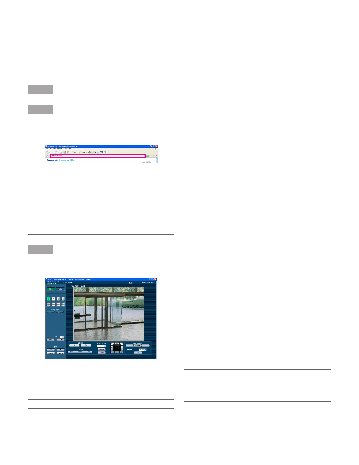
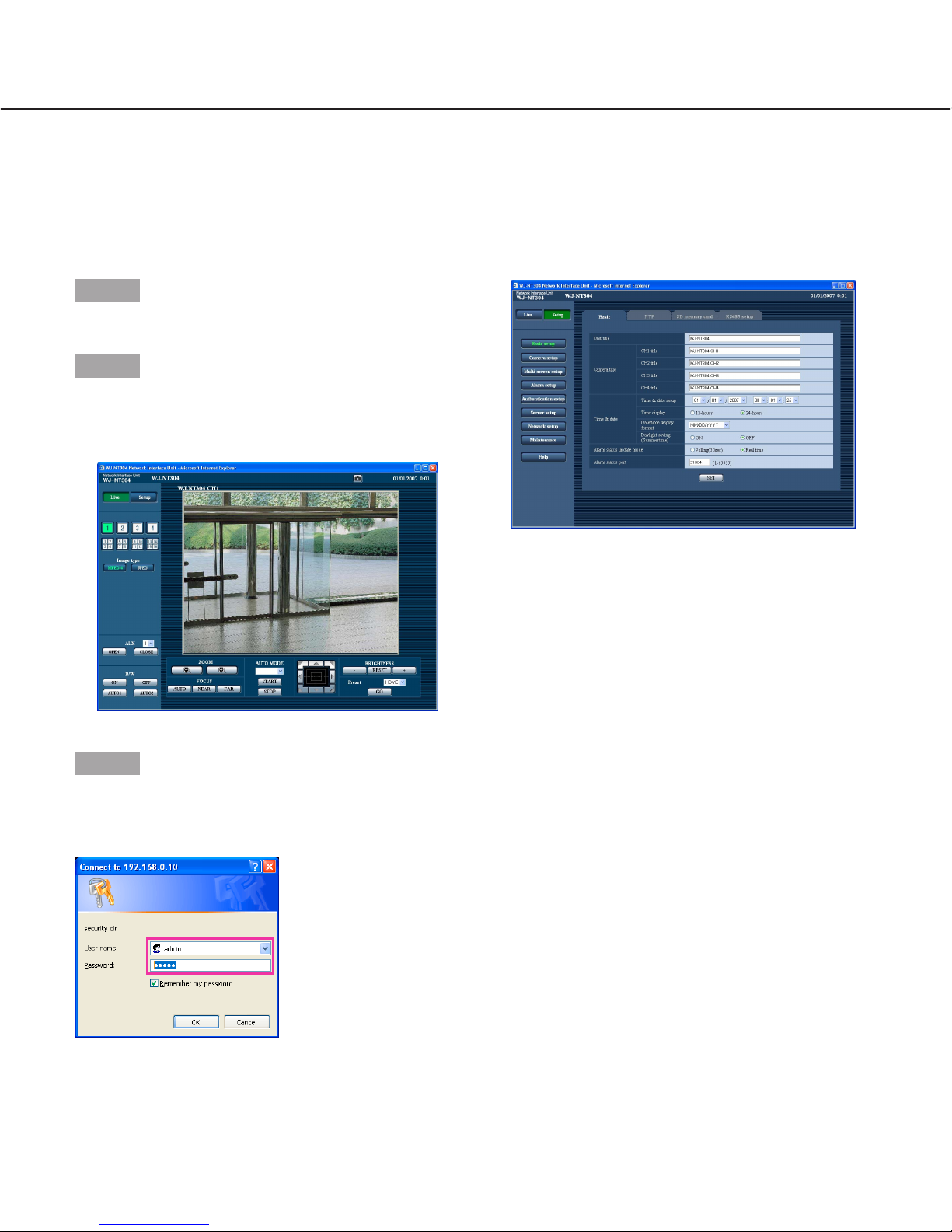
Step 1
Start up the web browser.
Step 2
Enter the IP address designated using the Panasonic IP
setup software in the address box of the browser.
(Example: http://192.168.0.10/)
Important:
• When the HTTP port number is changed from "80",
enter "http://IP address of the unit +: (colon) + port
number" in the address box of the browser, for
example, "http://192.168.0.11:8080".
• When the PC is in a local network, configure the
web browser to bypass the proxy server for the local
address.
Step 3
Press the [Enter] key on the keyboard.
→ The "Live" page will be displayed.
Important:
Follow the instructions on page 58 when the message is displayed on the information bar of the
browser.
Notes:
• When "ON" is selected for "User Authentication", the
authentication window will be displayed before displaying live images for the user name and password

5
About the "Live" page
q [Setup] button (*1)
Click this button to display the setup menu. The button will turn green and the setup menu will be displayed.
w [Live] button
The button will turn green and the "Live" page will be
displayed.
e [1] to [4] buttons
Click this button to display the "Live" page. The button will turn green and the "Live" page will be displayed. It is possible to select a desired channel by
clicking the [1] to [4] buttons.
r Multi-screen buttons
Images from multiple cameras can be displayed on
a multi-screen by registering cameras on the setup
menu. (☞ page 8)
t Image type buttons
: The letters "MPEG-4" on the button will
turn green and an MPEG-4 image will be
displayed. When "OFF" is selected for
"MPEG-4 transmission" on the setup
menu, the [MPEG-4] button will not be displayed. (☞ page 25)
: The letters "JPEG" on the button will turn
green and JPEG image will be displayed.
y AUX buttons (*2)
Select 1 (AUX1) to (AUX3) from the pull-down menu
and click the [OPEN/CLOSE] button.
AUX1 and AUX2 are auxiliary outputs of camera.
AUX3 is the auxiliary output from the AUX 1 terminal
of this unit.
: The AUX connector will open.
: The AUX connector will close.
w [Live] button
e [1] to [4] buttons
q [Setup] button
y AUX buttons
r Multi-screen buttons
t Image type buttons
i ZOOM buttons
o FOCUS buttons
!0 AUTO MODE !1 Control pad/buttons
!2 BRIGHTNESS buttons
!3 PRESET
!4 Unit title
!5 Alarm occurrence indication button
!6 Mic input button
!8 One shot button
!7 Audio output button
@0 Main area
u [B/W] button
!9 Time and date

6
u [B/W] button (*2)
Click the desired button to switch color (colour) of
the displayed images between color (colour) and
B/W.
: Images will be displayed in B/W (black and
white).
: Images will be displayed in color (colour).
: Activates Auto 1 mode. (The camera
selects black and white mode if the picture
is dark, or color mode if the picture is
bright enough.) If the camera has only one
AUTO mode, click this button.
: Activates Auto 2 mode. (The camera
detects the light source type to prevent
malfunction. This setting is applicable
when using a near-infrared light source in
a dark place.)
i ZOOM buttons (*2)
: Click this button to adjust the zoom ratio
to the WIDE side.
: Click this button to adjust the zoom ratio
to the TELE side.
o FOCUS buttons (*2)
: Click this button to adjust the focus auto-
matically.
: Click this button to adjust the focus to the
NEAR side.
: Click this button to adjust the focus to the
FAR side.
!0 AUTO MODE (*2)
Select an operation from the pull-down menu and
click the [START] button. The selected operation will
start.
Click the [STOP] button to stop the operation.
The selected operation will stop when the camera
(panning/tilting/zooming/focusing) is operated.
Auto pan: Automatically pans between the start
position and the end position set in advance.
Even when the camera is operated for zooming
or focusing, the camera continues panning.
Sort: Sequentially switches between preset posi-
tions counterclockwise, starting from the camera
home position.
Sequence: Automatically moves to the preset posi-
tions orderly (start from the lowest preset position number).
Patrol: Operates the camera in accordance with
patrol function settings.
Note:
To activate auto pan, sort, sequence, or patrol, it is
required to perform the settings on the SETUP
MENU of camera in advance. (☞ page 28)
!1 Control pad/buttons (*2)
: Left-click on the control pad or buttons
to adjust the horizontal/vertical position
of the camera (panning/tilting).
Panning/tilting speed will be faster if a
clicked point gets farther from the center
point of the control pad.
It is also possible to pan/tilt the camera by dragging
the mouse.
When the upper half area of the control pad is rightclicked, the displayed image will be zoomed in.
When the lower half area is right-clicked, the displayed image will be zoomed out on. When the left
half area is right-clicked, the focus will be adjusted to
the FAR side. When the right half area is rightclicked, the focus will be adjusted to the NEAR side.
!2 BRIGHTNESS buttons (*2)
: The displayed image will be darker.
: The adjusted brightness will return to the
default brightness.:
: The displayed image will be brighter.
Note:
When the BRIGHTNESS buttons are clicked while
the camera is at the preset position, the adjusted
brightness will automatically be registered for the
current preset position.
!3 PRESET (*2)
Select a preset position from the pull-down menu
and click the [GO] button. The camera will move to
the selected preset position. When "Home position"
is selected, the camera will move to the home position.
To activate preset positions and home position, it is
required to configure the settings on the SETUP
MENU of camera in advance. (☞ page 28)
!4 Unit title
The unit title entered for "Unit title" on the [Basic] tab
will be displayed. (☞ page 18)
7
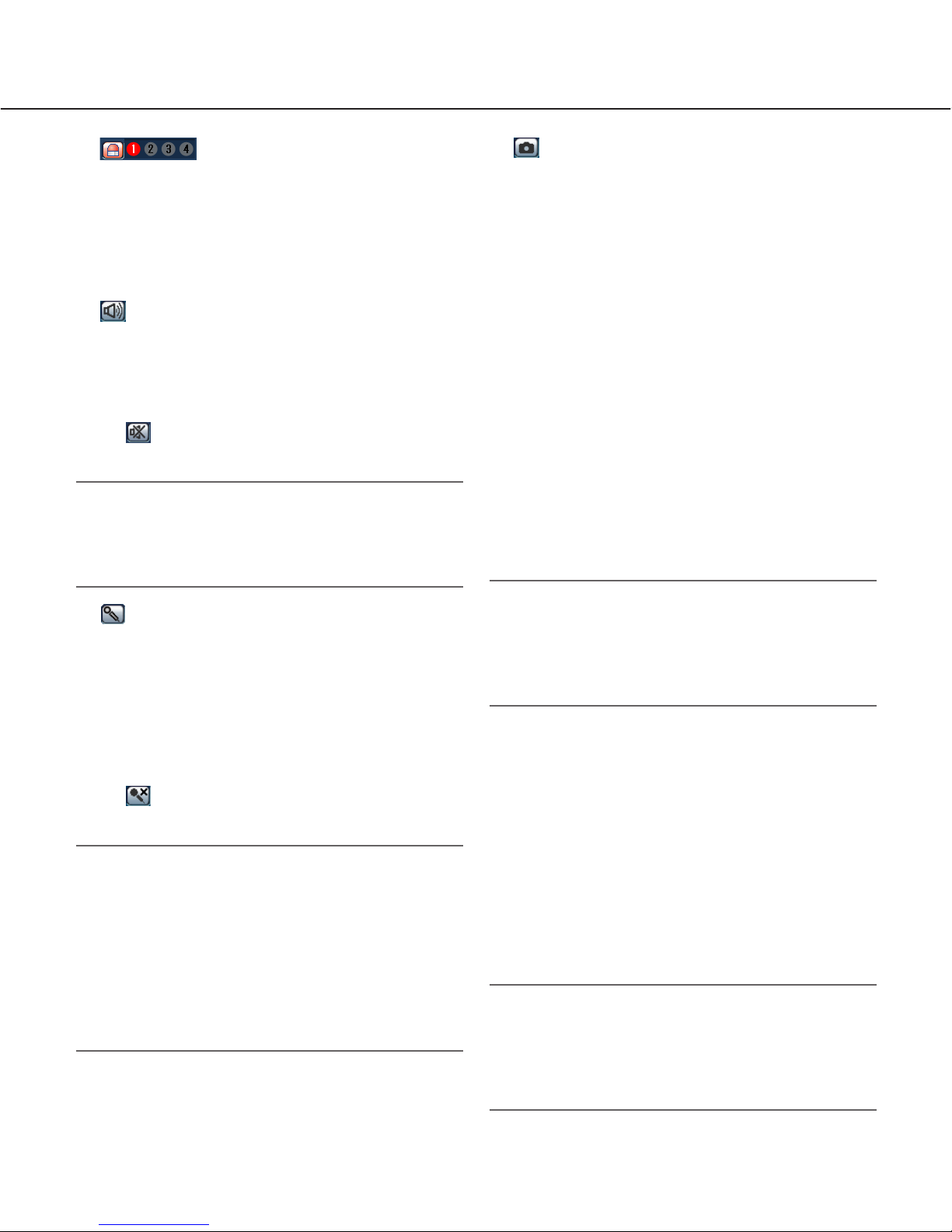
!5 Alarm occurrence indication
button (*2)
This button will be displayed at an alarm occurrence,
and the channel of alarm occurrence (one of [1] to
[4] buttons) will light. When the button is clicked, the
button will disappear and the alarm output connector
will be reset. (☞ page 34)
!6 Mic input button (*3)
Turns on/off the audio reception (hear audio from
the unit on a PC). This button will be displayed only
when "Mic input" or "Interactive" is selected for
"Audio mode" on the setup menu. (☞ page 29)
When this button is clicked, the button will turn into
the button and audio from the unit will not be
heard.
Note:
When this button is clicked, audio from the PC will
be turned off.
When closing the window, click the button again to
turn on the audio.
!7 Audio output button (*3)
Turns on/off the audio transmission (play audio from
the PC on the unit speaker). This button will be displayed only when "Audio output" or "Interactive" is
selected for "Audio mode" on the setup menu.
(☞ page 31)
The button blinks while the audio transmission is
being carried out.
When this button is clicked, the button will turn into
the button and audio from the PC will not be
heard.
Notes:
• When a user is using the audio transmission function, the mic input button and the audio output button
will be inoperable for the other users.
• Possible duration of audio transmission is up to 5
minutes per transmission. When 5 minutes have
passed, the audio transmission function will be canceled and the audio reception function will automatically be turned on. To turn the audio transmission
function on, click the audio output button again.
!8 One shot button
Click this button to take a picture (a still picture). The
picture will be displayed on a newly opened window.
The picture will be displayed on a newly opened window. When right-clicking on the displayed image, the
pop-up menu will be displayed. The displayed image
can be saved on the PC by selecting "Save" from
the pop-up menu.
!9 Time and date
Current time will be displayed in the set date/time
display format (☞ page 18).
@0 Main area (*2)
Images from the camera will be displayed in this
area.
Click a desired point in the main area on the "Live"
page that is to be the centre of the angle of view.
The camera moves to adjust the position in order to
set the clicked point as the centre.
Note:
When using this function, set "PROPO.P/T" of camera to ON. (☞ page 28)
The following cameras are available for the function.
WV-CS950 series, WV-CW960 series, WV-CW970
series (as of January 2007)
*1 Operable by only users and hosts whose access
level is "1. Administrator"
*2 Only operable by users and hosts whose access
level is "1. Administrator" or "2. Camera control"
when "ON" is selected for "User authentication"
(☞ page 37) and "Host authentication" (☞ page 38).
*3 Operable by users and hosts who belong to the
access level selected for "Authentication" on the
[Audio] tab of the "Camera setup" page. (☞ page 30)
Refer to page 37 for further information about the
access level.
Important:
It is impossible to display images and to receive/
transmit audio between the unit and the PC when
the viewer software "Network Camera View3" is not
installed on the PC. (Refer to the operating instructions for descriptions of how to install.)
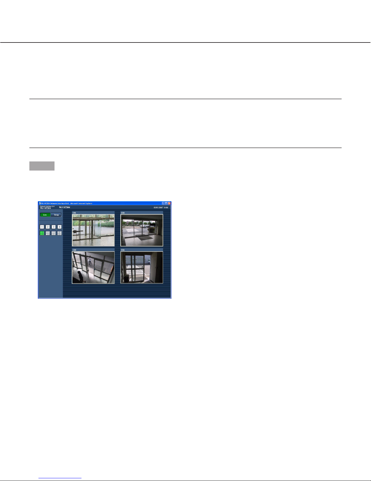
Monitor images from multiple cameras
Images from multiple cameras can be displayed on a multi-screen. Images from 4 cameras can be displayed simultaneously. To display images on a multi-screen, it is necessary to register cameras in advance. 4 cameras can be
registered as a group and up to 4 groups (16 cameras) can be registered. (☞ page 31)
Important:
• Select "OFF" for both the user authentication and the host authentication of the network device to be registered.
• Only JPEG images can be displayed on a multi-screen. Audio will not be heard.
• Multi-screen is the function that is available using this unit.
When the power is turned off or the LAN cable is disconnected while displaying images, displaying images on a
multi-screen will become unavailable.
8
Step 1
Click the [Multi-screen] button.
→ Images from the registered cameras will be displayed
on a 4-split screen.
q To display images on a single screen, click the the
[1] button or [Live] button.
w Click a camera title. Live images from the camera
corresponding to the clicked camera title will be displayed on the "Live" page of the newly opened window.

9
Action at an Alarm Occurrence
The alarm action will be performed when the following alarm occur.
Alarm type
Terminal alarm: When connecting an alarm device such as a sensor to the connector terminal (Alarm Input 1 to
4) on the rear of the unit, the alarm action (unit action at an alarm occurrence) will be performed when the
connected alarm device is activated. Alarm action to be performed differs depending on the settings configured on the [Alarm] tab. (☞ page 32)
Camera site alarm: When a camera connected to a VIDEO IN connector detects an alarm by alarm sensors or
cameras' motion detectors, etc., and the unit receives the alarm input signal from the camera, the alarm
action will be performed. (☞ page 32)
Video Loss: When the loss of video input signals is detected due to coaxial cable disconnections or camera
troubles, the alarm action will be performed. (☞ page 32)
Command alarm: When a Panasonic alarm protocol is received from the connected device via a network, the
alarm action will be performed. (☞ page 32)
Action at an Alarm Occurrence
Display the [Alarm occurrence indication] button on the "Live" page (☞ page 5).
The [Alarm occurrence indication] button will be displayed on the "Live" page at an alarm occurrence.
Note:
The [Alarm occurrence indication] button will be refreshed in 30 seconds intervals. For this reason, it may take a
maximum of 30 seconds until the [Alarm occurrence indication] button is displayed on the "Live" page at an alarm
occurrence.
Notify of alarm occurrences to the device connected to the alarm connector
It is possible to output signals from the alarm connector on the rear of the unit and sound the buzzer when an alarm
occurs. The settings for the alarm output can be configured on the [Alarm] tab of the "Alarm setup" page.
(☞ page 32)
Transmit an image onto a server automatically
An alarm image can be transmitted at an alarm occurrence to the server designated in advance. The settings
required to transmit an alarm image to a server can be configured in the "Alarm image setup" section of the [Alarm]
tab of the "Alarm setup" page (☞ page 33) and the [FTP] tab of the "Server setup" page (☞ page 40).
Notify of alarm occurrences by e-mail
Alarm mail (alarm occurrence notification) can be sent at an alarm occurrence to the e-mail addresses registered in
advance. Up to 4 addresses can be registered as recipients of the alarm mail. The settings for alarm mail can be
configured in the "E-mail notification setup" section of the [Notification] tab of the "Alarm setup" page (☞ page 35)
and the [Mail] tab of the "Server setup" page (☞ page 40).
Notify of alarm occurrences to the designated IP addresses (Panasonic alarm protocol)
This function is available only when Panasonic device, such as the network disk recorder, is connected to the system. When "ON" is selected for "Panasonic alarm protocol", the connected Panasonic device will be notified that the
unit is in the alarm state. The settings for Panasonic alarm protocol can be configured on the [Notification] tab of the
"Alarm setup" page. (☞ page 36)

10
Transmit Images onto an FTP Server
Images can be transmitted to an FTP server. By configuring the following settings, transmission of images captured
at an alarm occurrence or captured at a designated interval to an FTP server will become available.
Important:
When using this function, set the user name and the password to access the FTP server to restrict users who
can log into the FTP server.
Transmit an alarm image at an alarm occurrence (Alarm image
FTP transmission)
An alarm image can be transmitted at an alarm occurrence to the FTP server. To transmit alarm images to an FTP
server, it is necessary to configure the settings in advance.
The settings for the FTP server can be configured on the [FTP] tab of the "Server setup" page. (☞ page 40)
The alarm image FTP transmission function can be turned on/off on the [Alarm] tab of the "Alarm setup" page.
(☞ page 34)
Note:
Depending on the network traffic, number of the transmitted images may not reach the set number of images to
be transmitted.
Transmit images at a designated interval or period (FTP periodic
transmission)
Images can be transmitted at a designated interval or period. To transmit images at a designate interval or period, it
is necessary to configure the settings in advance.
The settings for the FTP server to which images are to be transmitted can be configured on the [FTP] tab of the
"Server setup" page. (☞ page 40)
On the [FTP] tab of the "Network setup" page, the FTP periodic transmission function can be turned on/off, and the
settings relating to schedules (periods) can be configured. (☞ page 46)
Notes:
• Depending on the network line speed or the network traffic, images may not be transmitted at the exact designated interval or period.
• When "ON" is selected for both of the alarm image FTP transmission function and the FTP periodic transmission
function, the alarm image FTP transmission function will be given priority over the FTP periodic transmission
function. For this reason, images may not be transmitted at the exact designated interval or period if alarms
occur frequently.

11
Save images on the SD memory card when failed to transmit
images by the FTP periodic transmission function
Images that have failed to transmit using the FTP periodic transmission can be saved automatically on the SD memory card.
When using the "SD memory REC" function of a Panasonic’s network disk recorder, select "OFF" for the "FTP periodic transmission" function. (☞ page 46) Refer to the operating instructions of network disk recorder for further information.
We make no guarantee for any damages of files on the SD memory card incurred by malfunction or error occurrence
in files saved on the SD memory card regardless of what the cause may be.
Possible capacity of images that can be saved on the SD memory card will be different depending on the number of
selected channels (☞ page 24), image capture size (☞ page 25), and image quality (☞ page 25).
When using an SD memory card, it is recommended to check the recording condition and select "5 sec" or longer for
"Interval" on the [FTP] tab. (☞ page 46)
Save images on the SD memory card
By selecting "Use" for "About SD memory card" on the [SD memory card] tab of the "Basic setup" page (☞ page 21),
saving images which had been failed to transmit to the FTP server using the FTP periodic transmission function will
become available.
Obtain images on the SD memory card
Step 1
Access the unit using the Windows command prompt or FTP client software.
→ The window with the user name and password entry fields will be displayed.
On the FTP server, only access the "sd_data" directory.
Note:
When accessing this unit via the FTP server, select "Allow" for "FTP access" on the [Network] tab of the
"Network setup" page. (☞ page 42)
Step 2
Enter the user name whose access level is "1. Administrator" and its password.
→ Log in the unit.
Note:
The default user name with the access level "1. Administrator" and its password are as follows.
User name: admin
Password: 12345
To enhance the security, it is recommended to change the password for the administrator periodically.
(☞ page 37)
12
Step 3
Move the current directory to "sd_data" and obtain images.
Note:
• When logging in the unit, each directory will be displayed. Images on the SD memory card can be found in the
"sd_data" directory. Move to the "sd_data" directory and obtain images.
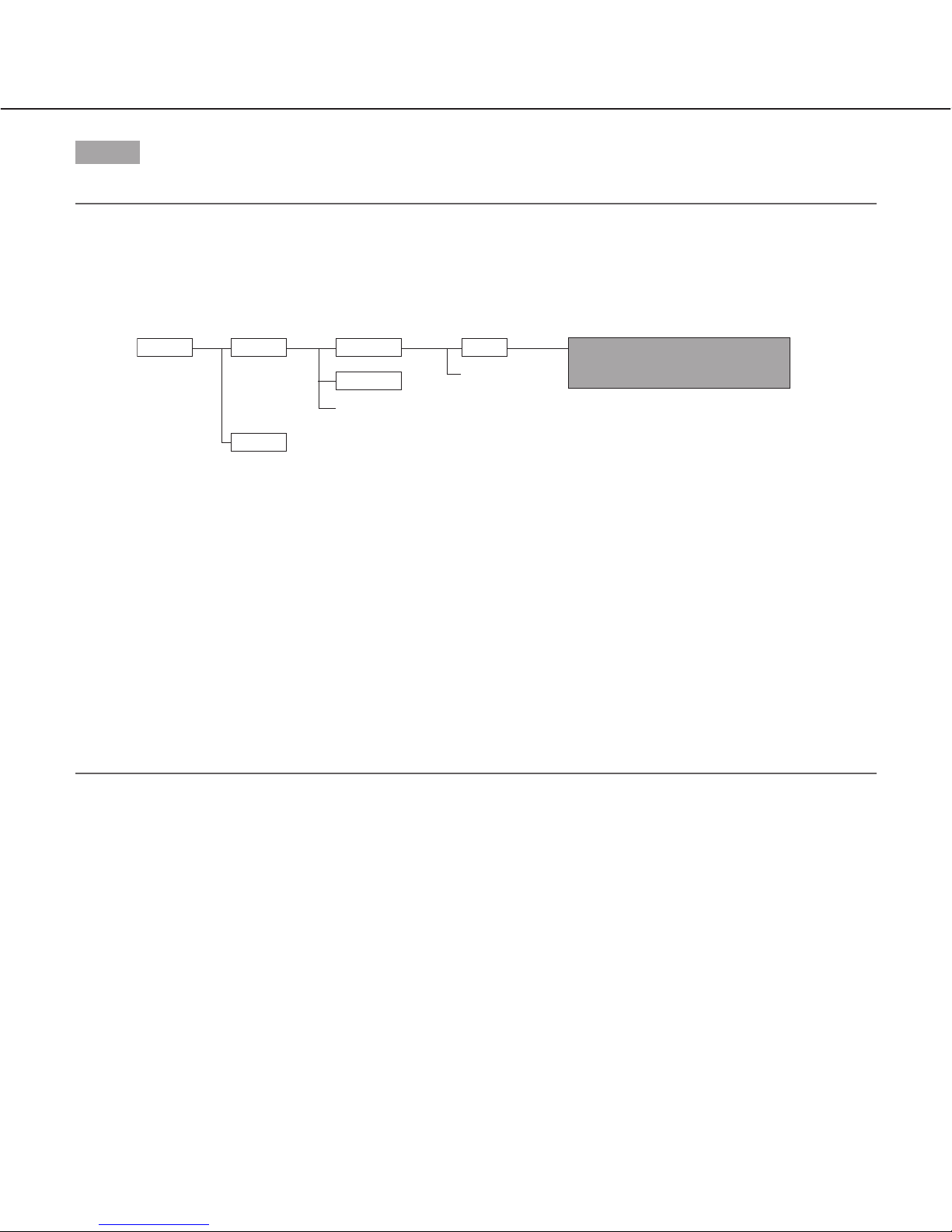
<Directory structure of "sd_data">
To obtain the image (img_0107010101230000.jpg) using the Windows command prompt
q Enter "c:\>ftp 192.168.0.10" and press the [Enter] key.
FTP connection will be established with "192.168.0.10".
w Log in by entering the user name and the password.
e Enter "ftp> cd sd_data/ftp/070101/0123" and press the [Enter] key.
→ The current directory will be "sd_data/070101/0123".
r The transfer mode will be set to the binary mode. Enter "ftp> bin" and press the [Enter] key.
t Obtain the image. Enter "ftp> get img_0107010101230000.jpg" and press the [Enter] key.
→ The image will be obtained.
y Log out by entering "ftp> bye" and press the [Enter] key.
→ You will log out of the "FTP" directory.
• It is possible to delete images on the SD memory card using the Windows command prompt, etc.
ftpsd_data
log
070101
070102
0123
Directory
Directory
(year/month/day)
Directory
(hour/minute)
:
:
:
:
:
:
:
:
← Destination of logs to be saved
↑ The image will be saved here.
An image failed to transmit by the FTP
periodic transmission function
(Ex. img_010701010123000.jpg)

13
About the Network Security of This Unit
Equipped security functions
The following security functions are featured in this unit.
q Access restrictions by the host authentication and the user authentication
It is possible to restrict users from accessing the unit by setting the host authentication and/or the user authentication to on. (☞ pages 37 and 38)
w Access restrictions by changing the HTTP port
It is possible to prevent illegal access such as port scanning, etc. by changing the HTTP port number.
(☞ page 42)
Note:
When user authentication (authentication error) has failed to pass 8 times (6 times when clicking the [Go] button
of the browser) within 5 minutes using the same IP address (PC), access to the unit will be denied for a while.
Important:
Design and enhance security countermeasures to prevent leakage of information such as image data, authentication information (user name and password), alarm mail information, FTP server information, DDNS server
information, etc.
14
Display the Setup Menu and Configure the Settings of the Unit using a PC
The settings of the unit can be configured on the setup menu.
The setup menu is only operable by users whose access level is "1. Administrator".
How to display the setup menu
Step 1
Display the "Live" page. (☞ page 4)
Step 2
Click the [Setup] button on the "Live" page.
→ The window with the user name and password entry
fields will be displayed.
Step 3
Click the [OK] button after entering the user name and
the password. (Refer to page 4 for the default user
name and password.)
→ Click this button to display the setup menu.
Refer to the next page for further information about
this menu.
15
Step 1
Click the desired button in the frame on the left of the
window to display the respective setup menu.
When there are tabs at the top of the setup page displayed in the frame on the right of the window, click the
desired tab to display and configure the setting items
relating to the name of the tab.
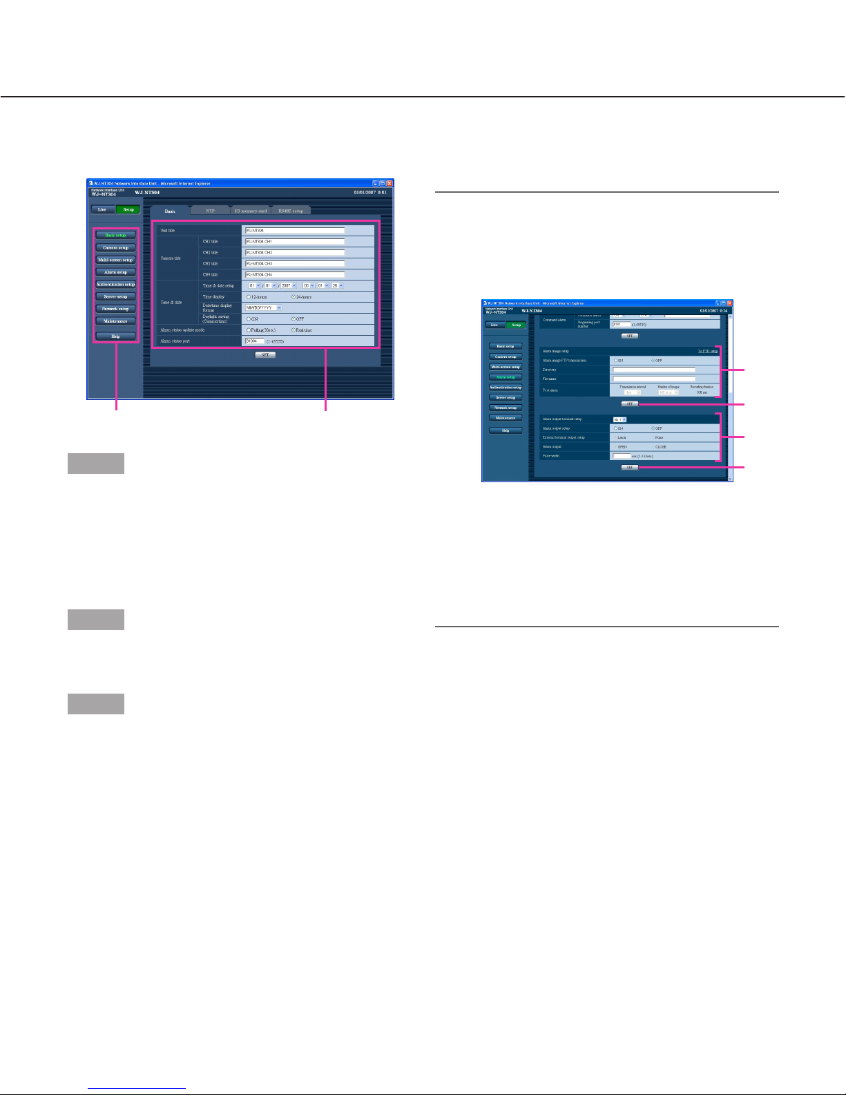
Step 2
Complete each setting item displayed in the frame on
the right of the window.
Step 3
After completing each setting item, click the [SET] button to apply them.
Important:
When there are two [SET] buttons (or [REG] buttons) or more on the page, click the respective button to the edited setting item.
<Example>
When completing the setting items in field A, click
the [SET] button below field A (A-1). The edited setting items in field A will not be applied unless the
[SET] button below field A (A-1) is clicked.
In the same manner as above, click the [SET] button
below field B (B-1) when completing the setting
items in field B.
How to operate the setup menu
A
A-1
B
B-1
Menu button Setup page
16
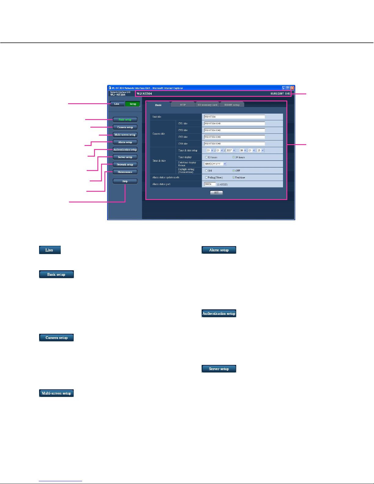
About the operation window
q [Live] button
The "Live" page will be displayed.
w [Basic setup] button
Click this button to display the "Basic setup" page.
The basic settings such as time and date and camera title, and the settings relating to the NTP server
and the SD memory card can be configured on the
"Basic setup" page. Refer to page 18 for further
information.
e [Camera setup] button
Click this button to display the "Camera setup" page.
The settings relating to JPEG/MPEG-4 images and
camera operation can be configured on the "Camera
setup" page. Refer to page 24 for further information.
r [Multi-screen setup] button
Click this button to display the "Multi-screen setup"
page. The cameras to be used for the multi-screen
display can be registered on the "Multi-screen setup"
page. Refer to page 31 for further information.
t [Alarm setup] button
Click this button to display the "Alarm setup" page.
The settings relating to alarm occurrences such as
settings for the alarm action at an alarm occurrence,
the alarm occurrence notification, and the VMD area
settings can be configured on the "Alarm setup"
page. Refer to page 32 for further information.
y [Authentication setup] button
Click this button to display the "Authentication setup"
page. The settings relating to the authentication
such as users and PCs restrictions for accessing the
unit can be configured on the "Authentication setup"
page. Refer to page 37 for further information.
u [Server setup] button
Click this button to display the "Server setup" page.
The settings relating to the mail server and the FTP
server to which the unit accesses can be configured
on the "Server setup" page. Refer to page 36 for further information.
!2 Setup page
!1 Status display
area
q [Live] button
w [Basic Setup] button
e [Camera setup] button
r [Multi-screen setup] button
t [Alarm setup] button
y [Authentication setup]
button
u [Server setup] button
i [Network setup] button
o [Maintenance] button
!0 [Help] button
17
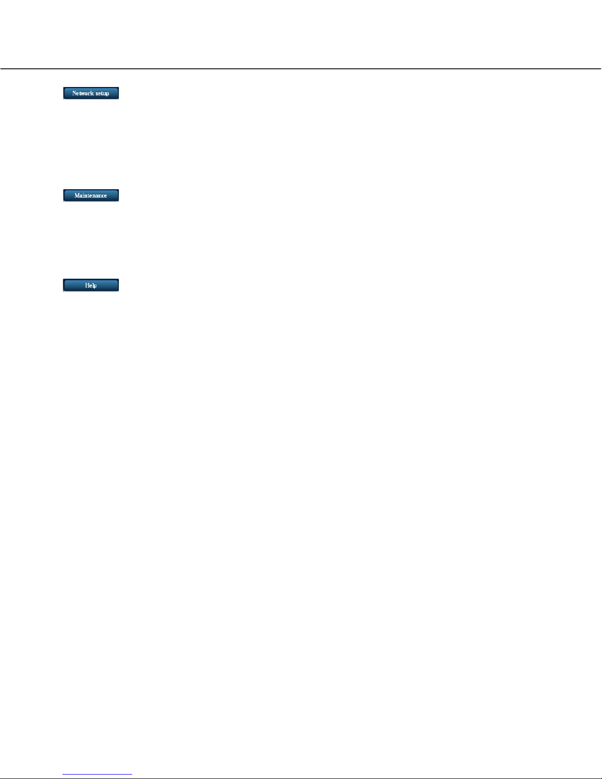
i [Network setup] button
Click this button to display the "Network setup" page.
The network settings and the settings relating to
DDNS (Dynamic DNS), SNMP (Simple Network
management Protocol) and FTP (File Transfer
Protocol) can be configured on the "Network setup"
page. Refer to page 41 for further information.
o [Maintenance] button
Click this button to display the "Maintenance" page.
System log check, firmware upgrade and initialization of the setup menu can be carried out on the
"Maintenance" page. Refer to page 48 for further
information.
!0 [Help] button
Click this button to display the "Help" page.
!1 Status display area
The name of the unit whose settings currently being
configured, and date and time will be displayed.
!2 Setup page
Pages of each setup menu will be displayed. There
are tabs for some setup menus.
18
Configure the basic settings of the unit [Basic setup]
The basic settings such as time and date and unit name, and the settings relating to the NTP server and the SD
memory card can be configured on the "Basic setup" page.
The "Basic setup" page has 4 tabs of the [Basic] tab, the [NTP] tab, [SD memory card] tab, and the [RS485 setup]
tab.
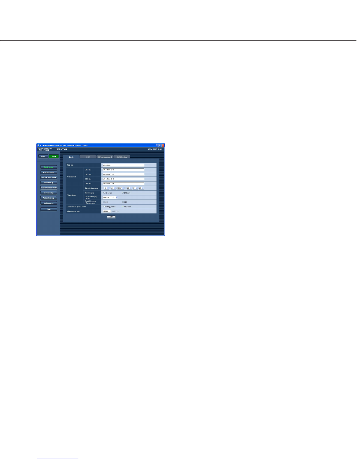
Configure the basic settings [Basic]
Click the [Basic] tab on the "Basic setup" page.
The settings such as the unit name, time and date, etc. can be configured on this page.
[Unit title]
Enter the title of the unit. Click the [SET] button after
entering the title of the unit. The entered title will be
displayed in the status display area.
Number of characters that can be entered: 0 - 20
characters
Default setting: WJ-NT304
[Camera title]
Enter the names of the cameras connected to VIDEO IN
connectors. The entered names will be displayed in the
status display area.
Number of characters that can be entered: 0 - 20
characters
Default setting: Name of CH1: WJ-NT304 CH1
Name of CH2: WJ-NT304 CH2
Name of CH3: WJ-NT304 CH3
Name of CH4: WJ-NT304 CH4
[Time & date setup]
Enter the current time and date. When "12-hours" is
selected for "Date/time display format", "AM" or "PM"
can be selected.
Available value: 01/01/2006 00: 00: 00 -
12/31/2035 23: 59: 59
[Time display]
Select the time display format from "12-hours", "24hours" and "OFF". Enter the current hour reflecting this
setting when entering the current time and date for
"Time & date setup".
Default setting: 12-hours (NTSC model)
24-hours (PAL model)
[Date/time display format]
Select a date/time display format.
When "04/01/2007 13: 10: 00" is set for "Time and date
setup" after selecting "24-hours" for "Date/time display
format", time and date will be displayed as follows
respectively.
DD/MM/YYYY: Apr/01/2007 13: 10
MM/DD/YYYY: Apr/01/2007 13: 10
DD/Mmm/YYYY: Apr/01/2007 13: 10
YYYY/MM/DD: Apr/01/2007 13: 10
Mmm/DD/YYYY: Apr/01/2007 13: 10
Default setting: Mmm/DD/YYYY (NTSC model)
DD/MM/YYYY (PAL model)
[Daylight saving (Summertime)]
Select "ON" or "OFF" to determine whether or not to
apply daylight saving time. Select "ON" or "OFF" to
determine whether or not to apply daylight saving time.
ON: Applies summer time. An asterisk (*) will be dis-
played on the left side of the displayed time and
date.
OFF: Does not apply summer time.
Default setting: OFF
 Loading...